EP4513625A1 - Batterieerwärmungssteuerungsverfahren und steuerungsvorrichtung - Google Patents
Batterieerwärmungssteuerungsverfahren und steuerungsvorrichtung Download PDFInfo
- Publication number
- EP4513625A1 EP4513625A1 EP22963765.7A EP22963765A EP4513625A1 EP 4513625 A1 EP4513625 A1 EP 4513625A1 EP 22963765 A EP22963765 A EP 22963765A EP 4513625 A1 EP4513625 A1 EP 4513625A1
- Authority
- EP
- European Patent Office
- Prior art keywords
- battery
- power grid
- heated
- present application
- heating
- Prior art date
- Legal status (The legal status is an assumption and is not a legal conclusion. Google has not performed a legal analysis and makes no representation as to the accuracy of the status listed.)
- Pending
Links
Images


Classifications
-
- B—PERFORMING OPERATIONS; TRANSPORTING
- B60—VEHICLES IN GENERAL
- B60L—PROPULSION OF ELECTRICALLY-PROPELLED VEHICLES; SUPPLYING ELECTRIC POWER FOR AUXILIARY EQUIPMENT OF ELECTRICALLY-PROPELLED VEHICLES; ELECTRODYNAMIC BRAKE SYSTEMS FOR VEHICLES IN GENERAL; MAGNETIC SUSPENSION OR LEVITATION FOR VEHICLES; MONITORING OPERATING VARIABLES OF ELECTRICALLY-PROPELLED VEHICLES; ELECTRIC SAFETY DEVICES FOR ELECTRICALLY-PROPELLED VEHICLES
- B60L58/00—Methods or circuit arrangements for monitoring or controlling batteries or fuel cells, specially adapted for electric vehicles
- B60L58/10—Methods or circuit arrangements for monitoring or controlling batteries or fuel cells, specially adapted for electric vehicles for monitoring or controlling batteries
- B60L58/24—Methods or circuit arrangements for monitoring or controlling batteries or fuel cells, specially adapted for electric vehicles for monitoring or controlling batteries for controlling the temperature of batteries
-
- H02J7/875—
-
- B—PERFORMING OPERATIONS; TRANSPORTING
- B60—VEHICLES IN GENERAL
- B60L—PROPULSION OF ELECTRICALLY-PROPELLED VEHICLES; SUPPLYING ELECTRIC POWER FOR AUXILIARY EQUIPMENT OF ELECTRICALLY-PROPELLED VEHICLES; ELECTRODYNAMIC BRAKE SYSTEMS FOR VEHICLES IN GENERAL; MAGNETIC SUSPENSION OR LEVITATION FOR VEHICLES; MONITORING OPERATING VARIABLES OF ELECTRICALLY-PROPELLED VEHICLES; ELECTRIC SAFETY DEVICES FOR ELECTRICALLY-PROPELLED VEHICLES
- B60L53/00—Methods of charging batteries, specially adapted for electric vehicles; Charging stations or on-board charging equipment therefor; Exchange of energy storage elements in electric vehicles
- B60L53/60—Monitoring or controlling charging stations
- B60L53/64—Optimising energy costs, e.g. responding to electricity rates
-
- B—PERFORMING OPERATIONS; TRANSPORTING
- B60—VEHICLES IN GENERAL
- B60L—PROPULSION OF ELECTRICALLY-PROPELLED VEHICLES; SUPPLYING ELECTRIC POWER FOR AUXILIARY EQUIPMENT OF ELECTRICALLY-PROPELLED VEHICLES; ELECTRODYNAMIC BRAKE SYSTEMS FOR VEHICLES IN GENERAL; MAGNETIC SUSPENSION OR LEVITATION FOR VEHICLES; MONITORING OPERATING VARIABLES OF ELECTRICALLY-PROPELLED VEHICLES; ELECTRIC SAFETY DEVICES FOR ELECTRICALLY-PROPELLED VEHICLES
- B60L58/00—Methods or circuit arrangements for monitoring or controlling batteries or fuel cells, specially adapted for electric vehicles
- B60L58/10—Methods or circuit arrangements for monitoring or controlling batteries or fuel cells, specially adapted for electric vehicles for monitoring or controlling batteries
- B60L58/18—Methods or circuit arrangements for monitoring or controlling batteries or fuel cells, specially adapted for electric vehicles for monitoring or controlling batteries of two or more battery modules
-
- G—PHYSICS
- G06—COMPUTING OR CALCULATING; COUNTING
- G06Q—INFORMATION AND COMMUNICATION TECHNOLOGY [ICT] SPECIALLY ADAPTED FOR ADMINISTRATIVE, COMMERCIAL, FINANCIAL, MANAGERIAL OR SUPERVISORY PURPOSES; SYSTEMS OR METHODS SPECIALLY ADAPTED FOR ADMINISTRATIVE, COMMERCIAL, FINANCIAL, MANAGERIAL OR SUPERVISORY PURPOSES, NOT OTHERWISE PROVIDED FOR
- G06Q50/00—Information and communication technology [ICT] specially adapted for implementation of business processes of specific business sectors, e.g. utilities or tourism
- G06Q50/06—Energy or water supply
-
- H—ELECTRICITY
- H01—ELECTRIC ELEMENTS
- H01M—PROCESSES OR MEANS, e.g. BATTERIES, FOR THE DIRECT CONVERSION OF CHEMICAL ENERGY INTO ELECTRICAL ENERGY
- H01M10/00—Secondary cells; Manufacture thereof
- H01M10/42—Methods or arrangements for servicing or maintenance of secondary cells or secondary half-cells
- H01M10/44—Methods for charging or discharging
- H01M10/441—Methods for charging or discharging for several batteries or cells simultaneously or sequentially
-
- H—ELECTRICITY
- H01—ELECTRIC ELEMENTS
- H01M—PROCESSES OR MEANS, e.g. BATTERIES, FOR THE DIRECT CONVERSION OF CHEMICAL ENERGY INTO ELECTRICAL ENERGY
- H01M10/00—Secondary cells; Manufacture thereof
- H01M10/60—Heating or cooling; Temperature control
- H01M10/61—Types of temperature control
- H01M10/615—Heating or keeping warm
-
- H—ELECTRICITY
- H01—ELECTRIC ELEMENTS
- H01M—PROCESSES OR MEANS, e.g. BATTERIES, FOR THE DIRECT CONVERSION OF CHEMICAL ENERGY INTO ELECTRICAL ENERGY
- H01M10/00—Secondary cells; Manufacture thereof
- H01M10/60—Heating or cooling; Temperature control
- H01M10/63—Control systems
-
- H—ELECTRICITY
- H01—ELECTRIC ELEMENTS
- H01M—PROCESSES OR MEANS, e.g. BATTERIES, FOR THE DIRECT CONVERSION OF CHEMICAL ENERGY INTO ELECTRICAL ENERGY
- H01M10/00—Secondary cells; Manufacture thereof
- H01M10/60—Heating or cooling; Temperature control
- H01M10/63—Control systems
- H01M10/633—Control systems characterised by algorithms, flow charts, software details or the like
-
- H—ELECTRICITY
- H01—ELECTRIC ELEMENTS
- H01M—PROCESSES OR MEANS, e.g. BATTERIES, FOR THE DIRECT CONVERSION OF CHEMICAL ENERGY INTO ELECTRICAL ENERGY
- H01M10/00—Secondary cells; Manufacture thereof
- H01M10/60—Heating or cooling; Temperature control
- H01M10/63—Control systems
- H01M10/637—Control systems characterised by the use of reversible temperature-sensitive devices, e.g. NTC, PTC or bimetal devices; characterised by control of the internal current flowing through the cells, e.g. by switching
-
- H—ELECTRICITY
- H02—GENERATION; CONVERSION OR DISTRIBUTION OF ELECTRIC POWER
- H02J—CIRCUIT ARRANGEMENTS OR SYSTEMS FOR SUPPLYING OR DISTRIBUTING ELECTRIC POWER; SYSTEMS FOR STORING ELECTRIC ENERGY
- H02J3/00—Circuit arrangements for AC mains or AC distribution networks
- H02J3/28—Arrangements for balancing of the load in a network by storage of energy
- H02J3/32—Arrangements for balancing of the load in a network by storage of energy using batteries with converting means
-
- H—ELECTRICITY
- H01—ELECTRIC ELEMENTS
- H01M—PROCESSES OR MEANS, e.g. BATTERIES, FOR THE DIRECT CONVERSION OF CHEMICAL ENERGY INTO ELECTRICAL ENERGY
- H01M10/00—Secondary cells; Manufacture thereof
- H01M10/60—Heating or cooling; Temperature control
- H01M10/62—Heating or cooling; Temperature control specially adapted for specific applications
- H01M10/625—Vehicles
-
- H—ELECTRICITY
- H01—ELECTRIC ELEMENTS
- H01M—PROCESSES OR MEANS, e.g. BATTERIES, FOR THE DIRECT CONVERSION OF CHEMICAL ENERGY INTO ELECTRICAL ENERGY
- H01M2220/00—Batteries for particular applications
- H01M2220/20—Batteries in motive systems, e.g. vehicle, ship, plane
-
- Y—GENERAL TAGGING OF NEW TECHNOLOGICAL DEVELOPMENTS; GENERAL TAGGING OF CROSS-SECTIONAL TECHNOLOGIES SPANNING OVER SEVERAL SECTIONS OF THE IPC; TECHNICAL SUBJECTS COVERED BY FORMER USPC CROSS-REFERENCE ART COLLECTIONS [XRACs] AND DIGESTS
- Y02—TECHNOLOGIES OR APPLICATIONS FOR MITIGATION OR ADAPTATION AGAINST CLIMATE CHANGE
- Y02E—REDUCTION OF GREENHOUSE GAS [GHG] EMISSIONS, RELATED TO ENERGY GENERATION, TRANSMISSION OR DISTRIBUTION
- Y02E60/00—Enabling technologies; Technologies with a potential or indirect contribution to GHG emissions mitigation
- Y02E60/10—Energy storage using batteries
Definitions
- the present application relates to the technical field of batteries, and particularly relates to a battery heating control method and a control device.
- batteries are widely applied to the fields such as new energy vehicles, consumer electronics and energy storage systems.
- the use of the batteries can be limited in a low-temperature environment.
- the discharge capacity of the batteries can be severely degraded in a low-temperature environment, and the batteries cannot be charged in a low-temperature environment, thereby affecting user experience.
- the batteries need to be heated in a low-temperature environment.
- an additional heating assembly is usually arranged in the battery to heat the battery. This heating method increases energy consumption for battery heating, thereby increasing the battery heating cost.
- Embodiments of the present application provide a battery heating control method and a control device, through which power consumption for battery heating and the heating cost of batteries can be reduced.
- a first aspect provides a battery heating control method.
- the control method is applied to a battery heating system including a plurality of batteries connected with each other.
- the control method includes: determining that a first battery in the battery heating system needs to be heated; and controlling the first battery to conduct charging and discharging to heat the first battery, where the first battery is discharged to a second battery in the battery heating system.
- the first battery can be controlled to be discharged to the second battery in the case that the first battery needs to be heated so that the first battery is heated by heat generated during the process of discharging the first battery to the second battery and charging the first battery, thereby being capable of saving energy for battery heating and reducing the battery heating cost.
- controlling the first battery to conduct charging and discharging includes: controlling the first battery and the second battery to conduct charging and discharging with each other to heat the first battery and the second battery in the case that the second battery needs to be heated.
- the first battery and the second battery can be controlled to conduct charging and discharging with each other in the case that both the first battery and the second battery need to be heated so that the first battery and the second battery can be heated simultaneously by heat generated during the process of charging and discharging of the first battery and charging and discharging of the second battery, thereby being capable of improving the battery heating efficiency and saving energy required for battery heating.
- the battery heating control scheme there is little need to add an additional heating assembly and the like to the battery, and thus the battery heating cost can be reduced.
- controlling the first battery to conduct charging and discharging includes: controlling a dischargeable third battery to charge the first battery in the case that the third battery exists in the battery heating system and the second battery does not need to be heated.
- the battery heating control scheme provided in the embodiment of the present application in the case that the dischargeable third battery exists in the battery heating system and the second battery does not need to be heated, heating the first battery and charging the second battery are implemented simultaneously through charging the first battery by the third battery and discharging the first battery to the second battery, economic factors of battery charging and battery heating are considered, energy for battery heating can be saved, and the battery heating efficiency can be improved.
- the battery heating control scheme provided in the embodiment of the present application there is little need to add an additional heating assembly and the like to the battery, and thus the battery heating cost can be reduced.
- the controlling the first battery to conduct charging and discharging includes: controlling the power grid and/or the energy generation system to charge the first battery in the case that the second battery does not need to be heated.
- the battery heating control scheme in the case that the battery heating system is connected to the power grid and/or the energy generation system, the power grid and/or the energy generation system can be controlled to charge the first battery, and the first battery can be controlled to be discharged to the second battery.
- the second battery can be charged while the first battery is heated. Economic factors of battery charging and battery heating are considered, energy for battery heating can be saved, and the battery heating efficiency can be improved.
- the battery heating control scheme there is little need to add an additional heating assembly and the like to the battery, and thus the battery heating cost can be reduced.
- controlling the power grid and/or the energy generation system to charge the first battery includes: controlling the power grid and/or the energy generation system to charge the first battery in the case that the power grid is at a valley period electricity price and/or residual output energy exists in the energy generation system.
- the power grid and/or the energy generation system is controlled to charge the first battery, and economic factors of battery heating are considered, and the battery heating cost can be reduced.
- the power grid and/or the energy generation is controlled to charge the first battery in the case that a dischargeable third battery exists in the battery heating system, the power grid is at a valley period electricity price and/or residual output energy exists in the energy generation system and the second battery does not need to be heated.
- the power grid and/or the energy generation system can be controlled to charge the first battery, the first battery is controlled to be discharged to the second battery, economic factors of battery heating are considered, and the battery heating cost is reduced.
- the battery heating control scheme by controlling to reduce the number of charging cycles of the first battery by the power grid and/or the energy generation system and discharging cycles of the first battery to the second battery, the number of charging and discharging times can be reduced to some extent, the performance of the third battery can be improved, and the service life of the third battery can be prolonged.
- the battery heating system is connected to the power grid and/or the energy generation system
- the controlling the first battery to conduct charging and discharging includes: controlling a dischargeable third battery to charge the first battery in the case that the dischargeable third battery exists in the battery heating system, the power grid is at a peak-valley electricity price and/or no residual output energy exists in the energy generation system and the second battery does not need to be heated.
- the third battery can be controlled to charge the first battery, the first battery is controlled to be discharged to the second battery, economic factors of battery heating are considered, and the battery heating cost can be reduced.
- the first battery is a traction battery or an energy storage battery
- the second battery is a traction battery or an energy storage battery.
- batteries to be heated can be heated by heat generated during the process of charging and discharging of the batteries in an energy storage charging station, economic factors are considered in the process of heating the batteries, energy for battery heating is saved, the battery heating cost is reduced, and the yield of the energy storage charging station is increased.
- both the first battery and the second battery are traction batteries, and the third battery is an energy storage battery.
- a first traction battery can be heated and a second traction battery can be charged simultaneously by charging the first traction battery (the first battery) through the energy storage battery and discharging the first traction battery to the second traction battery, energy for battery heating can be saved, and the battery heating cost can be reduced.
- a second aspect provides a battery heating control device.
- the control device is applied to a battery heating system including a plurality of batteries connected with each other.
- the control device includes a determination unit for determining that a first battery in the battery heating system needs to be heated; and a control unit for controlling the first battery to conduct charging and discharging to heat the first battery, wherein the first battery is discharged to a second battery in the battery heating system.
- control unit is configured to control the first battery and the second battery to conduct charging and discharging with each other to heat the first battery and the second battery in the case that the second battery needs to be heated.
- control unit is configured to control a dischargeable third battery to charge the first battery in the case that the dischargeable third battery exists in the battery heating system and the second battery does not need to be heated.
- the battery heating system is connected to a power grid and/or an energy generation system
- the control unit is configured to control the power grid and/or the energy generation system to charge the first battery in the case that the second battery does not need to be heated.
- control unit is configured to control the power grid and/or the energy generation system to charge the first battery in the case that the power grid is at a valley period electricity price and/or residual output energy exists in the energy generation system.
- the power grid and/or the energy generation is controlled to charge the first battery in the case that a dischargeable third battery exists in the battery heating system, the power grid is at a valley period electricity price and/or residual output energy exists in the energy generation system and the second battery does not need to be heated.
- the battery heating system is connected to the power grid and/or the energy generation system, and the control unit is configured to control a dischargeable third battery to charge the first battery in the case that the dischargeable third battery exists in the battery heating system, the power grid is at a peak-valley electricity price and/or no residual output energy exists in the energy generation system.
- the first battery is a traction battery or an energy storage battery
- the second battery is a traction battery or an energy storage battery.
- both the first battery and the second battery are traction batteries, and the third battery is an energy storage battery.
- a third aspect provides a battery heating system, including a plurality of batteries connected with each other and the control device in the second aspect and any one of the possible implementations in the second aspect above.
- a fourth aspect provides a battery heating control device.
- the control device includes a memory and a processor.
- the memory is used to store instructions.
- the processor is used to read the instructions and perform the method in the first aspect and any one of the possible implementations in the first aspect according to the instructions.
- a fifth aspect provides a chip, including a processor for calling a computer program from the memory and running the computer program to enable a device provided with the chip to perform the method in the first aspect and any one of the possible implementations in the first aspect.
- a sixth aspect provides a computer program, wherein the computer program is executed to enable a computer to implement the method in the first aspect and any one of the possible implementations in the first aspect.
- a seventh aspect provides a computer-readable storage medium for storing a computer program.
- the computer program is executed by a computer to enable the computer to implement the method in the first aspect and any one of the possible implementations in the first aspect.
- An eighth aspect provides a computer program product including a computer program instruction.
- the computer program instruction is executed by a computer to enable the computer to implement the method in the first aspect and any one of the possible implementations in the first aspect.
- batteries are widely applied to the fields such as new energy vehicles, consumer electronics and energy storage systems.
- the use of the batteries can be limited in a low-temperature environment.
- the discharge capacity of the batteries can be severely degraded in a low-temperature environment, and the batteries cannot be charged in a low-temperature environment, thereby affecting user experience.
- the batteries need to be heated in a low-temperature environment.
- an additional heating element is usually arranged in a battery to heat the battery. According to the heating method, the energy required for battery heating is large, thereby increasing the battery heating cost.
- the embodiments of the present application provide a battery heating control method, which is applied to a battery heating system including a plurality of batteries connected with each other.
- a first battery in the battery heating system can be determined to need to be heated; the first battery is controlled to conduct charging and discharging to heat the first battery, wherein the first battery is discharged to a second battery in the battery heating system.
- the first battery can be controlled to be discharged to the second battery in the case that the first battery needs to be heated so that the first battery is heated by heat generated during the process of discharging the first battery to the second battery and charging the first battery, thereby being capable of saving energy for battery heating and reducing the battery heating cost.
- FIG. 1 is a structural diagram of a battery heating system applicable to the embodiment of the present application.
- the battery heating system may include a plurality of batteries: battery 111, battery 112, battery 113, ..., and battery 11n which are connected with each other.
- the battery heating system may include a plurality of current converters, for example, bidirectional direct current/alternating current (DC/AC) converters: current converter 121, current converter 121, current converter 123, ..., and current converter 12n, the plurality of batteries can be connected to one end of a plurality of current converters, and the other ends of the plurality of current converters can be connected with each other.
- the battery 111 can be connected with one end of the current converter 121
- the battery 112 can be connected with one end of the current converter 121, ...
- the battery 11n can be connected to one end of the current converter 12n.
- the other ends of the current converter 121, the current converter 121, the current converter 123, ..., and the current converter 12n are connected with each other, thereby being capable of realizing interconnection of the plurality of batteries.
- the other ends of the plurality of current converters can be connected to an AC bus 130.
- Interconnection of the plurality of batteries can be realized through the connection of the plurality of the current converters and the AC bus 130.
- the plurality of batteries may include energy storage batteries and/or traction batteries.
- the plurality of batteries may be batteries in an energy storage charging system such as a charging station.
- the battery heating system can be connected to a power grid 140.
- the power grid 140 can be connected to the AC bus 130 to realize the connection of the plurality of batteries and the power grid 140.
- the power grid 140 can be connected to the AC bus 130 through a grid side current converter.
- One end of the grid side current converter is connected to the power grid 140, and the other end of the grid side current converter is connected to the AC bus 130.
- the battery heating system can be connected to an energy generation system 150.
- the energy generation system 150 can be connected to the AC bus 130 to realize the connection of the plurality of batteries and the energy generation system.
- the energy generation system 150 can be connected to the AC bus 130 through an energy generation system side current converter.
- One end of the energy generation system side current converter is connected to the energy generation system 150, and the other end of the energy generation system side current converter is connected to the AC bus 130.
- the energy generation system 150 may be one or more of a thermal power generation system, a hydraulic power generation system or a new energy power generation system.
- the power grid 140 can be connected to the energy generation system 150.
- a battery A and a battery B can conduct charging and discharging with each other to heat the battery A and the battery B through heat generated during charging and discharging.
- the battery 111 and the battery 112 can conduct charging and discharging with each other.
- the battery A can charge the battery B, and the battery B can be discharged to a battery C, thereby being capable of heating the battery B.
- the battery 111 can charge the battery 112, and the battery 112 can be discharged to the battery 113.
- the power grid 140 can charge the battery A, and the battery A can be discharged to the battery B, thereby being capable of heating the battery A.
- the power grid 140 can charge the battery 111, and the battery 111 can be discharged to the battery 112.
- the energy generation system 150 can charge the battery A, and the battery A can be discharged to the battery B, thereby being capable of heating the battery A.
- the energy generation system 150 can charge the battery 111, and the battery 111 can be discharged to the battery 112.
- the plurality of batteries may be a plurality of traction batteries in a vehicle such as an electric car.
- the power grid 140 can be replaced with a motor or an energy storage element and the like in the vehicle, and the current converters 121-12n can be replaced with power devices and the like in the vehicle.
- FIG. 2 is a schematic flow diagram of the battery heating control method provided according to the embodiment of the present application.
- the battery heating control method is applicable to the battery heating system including the plurality of batteries connected with each other as shown in FIG. 1 .
- a battery management system (BMS) in the first battery can monitor battery information of the battery such as the temperature of the battery.
- BMS battery management system
- the first battery can send a battery heating request to a controller in the battery management system.
- the controller in the battery heating system can determine that the first battery in the battery heating system needs to be heated according to the received battery heating request.
- the BMS in the battery can monitor temperature information of the battery in real time and send the temperature information to the controller in the battery heating system.
- the controller in the battery heating system can determine that the first battery needs to be heated according to the received real-time temperature information of the first battery.
- the first battery during the process of normal charging or normal discharging of the first battery, when the temperature of the first battery is lowered to be less than or equal to the preset temperature, the first battery needs to be heated.
- the first battery when the first battery does not conduct charging and discharging and the temperature of the first battery is lowered to be less than or equal to the preset temperature, the first battery needs to be heated.
- the first battery when the temperature of the first battery is less than or equal to the preset temperature, it can be determined that the first battery needs to be heated.
- the first battery when the first battery does not conduct charging and discharging and the temperature of the first battery is lowered to be less than or equal to the preset temperature, if the electric apparatus does not need to use the first battery (the electric apparatus does not need normal discharging of the first battery), the first battery temporarily does not need to be heated. In the case that the first battery does not conduct charging and discharging and the temperature of the first battery is lowered to be less than or equal to the preset temperature, when the electric apparatus needs to use the first battery (the electric apparatus needs normal charging of the first battery), the first battery needs to be heated.
- the electric apparatus completes charging and the temperature of the first battery is lowered to be less than or equal to the preset temperature, if the electric apparatus needs to use electricity of the electric apparatus at some moment, it can be determined at the moment that the first battery needs to be heated.
- normal charging or normal discharging of the first battery in the embodiment of the present application refers to continuous charging or continuous discharging of the first battery above the preset temperature.
- the controlling the first battery to conduct charging and discharging to heat the first battery refers to transitory charging and transitory discharging when the temperature of the first battery is less than or equal to the preset temperature, for example, pulse cyclic charging and discharging.
- the first battery is discharged to the second battery in the battery heating system.
- the first battery when the first battery is controlled to conduct charging and discharging, the first battery can be controlled to conduct charging and then to be discharged to the second battery, or the first battery can be controlled to be discharged to the second battery and then to conduct charging.
- the first battery can be controlled to be discharged to the second battery in the case that the first battery needs to be heated so that the first battery is heated by heat generated during the process of discharging the first battery to the second battery and charging the first battery, thereby being capable of saving energy for battery heating and reducing the battery heating cost.
- FIG. 3 is another schematic flow diagram of the battery heating control method provided according to the embodiment of the present application.
- the battery heating control method is applicable to a battery heating system including a plurality of batteries connected with each other.
- Step 310 can refer to the related description in Step 210, which will not be described here according to the present application.
- the second battery may be a battery which needs to be heated with the first battery simultaneously.
- the second battery may also be a battery which already needs to be heated before the first battery needs to be heated and still needs to be heated when the first battery needs to be heated.
- the second battery needs to be heated according to a battery heating request sent by the second battery.
- the second battery it can be determined that the second battery needs to be heated according to temperature information of the second battery sent by the second battery.
- either one battery that needs to be heated and another battery that needs to be heated are connected to conduct charging and discharging with each other, or one battery that needs to be heated and multiple batteries that need to be heated to conduct charging and discharging with each other, or multiple batteries that need to be heated and the multiple batteries that need to be heated conduct charging and discharging with each other.
- a battery 1, a battery 2, a battery 3 and a battery 4 in the battery heating system need to be heated, the battery 1 and the battery 2 can be controlled to conduct charging and discharging with each other, and the battery 3 and the battery 4 are controlled to conduct charging and discharging with each other; or the battery 1 is controlled to be discharged to the battery 2, the battery 3 and the battery 4, and then the battery 2, the battery 3 and the battery 4 are controlled to charge the battery 1; or the battery 1 and the battery 2 are controlled to be discharged to the battery 3 and the battery 4, and then the battery 3 and the battery 4 are controlled to conduct charging on the battery 1 and the battery 2.
- the first battery and the second battery can be controlled to conduct charging and discharging with each other in the case that both the first battery and the second battery need to be heated so that the first battery and the second battery can be heated simultaneously by heat generated during the process of charging and discharging of the first battery and charging and discharging of the second battery, thereby being capable of saving energy required for battery heating, reducing the battery heating cost and improving the battery heating efficiency.
- the battery heating control scheme provided in the embodiment of the present application there is little need to add an additional heating assembly and the like to the battery, and thus the battery heating cost can be reduced.
- FIG. 4 is a schematic flow diagram of the battery heating control method provided according to the embodiment of the present application.
- the battery heating control method is applicable to a battery heating system including a plurality of batteries connected with each other.
- the battery heating system may further include a dischargeable third battery.
- the battery heating control method may include a portion of or all of the following content.
- Step 410 can refer to the related description in Step 210, which will not be described here according to the present application.
- Step 420 can refer to the related description in Step 320, which will not be described here according to the present application.
- the number of the first battery, the second battery or the third battery may be one or more.
- a battery 1 that needs to be heated, a battery 2 that does not need to be heated and a dischargeable battery 3 exist in the battery heating system the battery 3 can be controlled to charge the battery 1, and the battery 1 is controlled to be discharged to the battery 2.
- the battery 4 can be controlled to charge the battery 1 and the battery 2, and then the battery 1 and the battery 2 are controlled to be discharged to the battery 3.
- a battery 1, a battery 2, a battery 3 and a battery 4 that need to be heated, a battery 5 and a battery 6 that do not need to be heated and a dischargeable battery 7 exist in the battery heating system
- the battery 7 can be controlled to charge the battery 1, the battery 2, the battery 3 and the battery 4, and then the battery 1, the battery 2, the battery 3 and the battery 4 are controlled to be discharged to the battery 5 and the battery 6; or the battery 1 and the battery 2 are controlled to conduct charging and discharging with each other, the battery 7 is controlled to be discharged to the battery 3 and the battery 4, and then the battery 3 and the battery 4 are controlled to be discharged to the battery 5 and the battery 6.
- the second battery can be a battery in the battery heating system that needs to be charged.
- the battery in the battery heating system of which SOC is less than or equal to SOC charging threshold and the temperature is greater than or equal to the preset temperature may be a battery that needs to be charged.
- the second battery it can be determined that the second battery needs to be charged according to a charging request of the second battery. For example, when of the second battery is less than or equal to SOC charging threshold and the temperature of the second battery is greater than or equal to the preset temperature, the second battery can send a charging request to the controller of the battery heating system.
- the second battery needs to be charged according to the information of the second battery such as SOC and temperature.
- the BMS of the second battery can send information of the second battery such as SOC and temperature to the controller in the battery heating system.
- the controller in the battery heating system can determine that the second battery needs to be charged.
- the SOC charging threshold of different batteries can be determined according to service demands and performance of the batteries.
- the SOC charging threshold of different batteries can be the same or different.
- the SOC charging threshold of an energy storage battery can be set larger, and the SOC charging threshold of a traction battery can be set smaller.
- the second battery may be a battery in the battery heating system that does not need to be charged and heated.
- the second battery may be a battery in a heating system of which SOC satisfies: SOC charging threshold ⁇ SOC ⁇ SOC max and the temperature is greater than or equal to the preset temperature, for example, an energy storage battery in the battery heating system of which SOC satisfies: SOC charging threshold ⁇ SOC ⁇ SOC max and the temperature is greater than or equal to the preset temperature.
- SOC charging threshold ⁇ SOC ⁇ SOC max an energy storage battery in the battery heating system of which SOC satisfies: SOC charging threshold ⁇ SOC ⁇ SOC max and the temperature is greater than or equal to the preset temperature.
- the second battery does not need to be charged, and the second battery can be charged.
- the second battery may be a battery in the heating system in which charging is completed, SOC satisfies: SOC charging threshold ⁇ SOC restart charging threshold ⁇ SOC ⁇ SOC max and the temperature is greater than or equal to the preset temperature.
- SOC charging threshold ⁇ SOC restart charging threshold
- SOC ⁇ SOC max the temperature is greater than or equal to the preset temperature.
- the second battery When the SOC of the second battery decreases to SOC restart charging threshold ⁇ SSOC ⁇ SOC max , the second battery does not need to be charged and is rechargeable; and when the SOC of the second battery decreases to SOC restart charging threshold and the temperature of the second battery is greater than or equal to the preset temperature, the second battery needs to be recharged.
- the second battery in the case that the second battery does not need to be heated and charged, the second battery has no charging demand. If there is energy to be input, the second battery can still receive the energy.
- the SOC of the dischargeable third battery is greater than or equal to SOC discharging threshold .
- the third battery may be an energy storage battery of which SOC is greater than or equal to SOC discharging threshold .
- the temperature of the dischargeable third battery is greater than or equal to the preset temperature.
- the battery heating control scheme provided in the embodiment of the present application in the case that the dischargeable third battery exists in the battery heating system and the second battery does not need to be heated, the first battery and the second battery can be charged simultaneously by charging the first battery by the third battery and discharging the first battery to the second battery, economic factors of battery charging are considered, energy for battery heating can be saved, and the battery heating efficiency can be improved.
- the battery heating control scheme provided in the embodiment of the present application there is little need to add an additional heating assembly and the like to the battery, and thus the battery heating cost can be reduced.
- FIG. 5 is a schematic flow diagram of the battery heating control method provided according to the embodiment of the present application.
- the battery heating control method is applicable to a battery heating system including a plurality of batteries connected with each other.
- the battery heating system can be connected to an energy generation system/or a power grid.
- the battery heating control method may include a portion of or all of the following content.
- Step 510 can refer to the related description in Step 210, which will not be described here according to the present application.
- Step 520 can refer to the related description in Step 320, which will not be described here according to the present application.
- the number of the first battery or the second battery may be one or more.
- a battery system includes a battery 1 that needs to be heated and a battery 2 that does not need to be heated and can control the power grid and/or the energy generation system to charge the battery 1 and control the battery 1 to be discharged to the battery 2.
- a battery system includes a battery 1 and a battery 2 that need to be heated and a battery 3 and a battery 4 that do not need to be heated, can control the power grid and/or the energy generation system to charge the battery 1 and the battery 2 and control the battery 1 and the battery 2 to be discharged to the battery 3 and the battery 4, and can also control the power grid and/or the energy generation system to charge the battery 1 and the battery 2, control the battery 1 to be discharged to the battery 3 and control the battery 2 to be discharged to the battery 4.
- a battery system includes a battery 1, a battery 2, a battery 3 and a battery 4 that need to be heated and a battery 5 and a battery 6 that do not need to be heated, can control the battery 1 and the battery 2 to conduct charging and discharging with each other, control the power grid and/or the energy generation system to charge the battery 3 and the battery 4, and then control the battery 3 and the battery 4 to be discharged to the battery 5 and the battery 6, and can also control the power grid and/or the energy generation system to charge the battery 1, the battery 2, the battery 3 and the battery 4 and control the battery 1, the battery 2, the battery 3 and the battery 4 to be discharged to the battery 5 and the battery 6.
- the second battery can be a battery in the battery heating system that needs to be charged.
- the battery in the battery heating system of which SOC is less than or equal to SOC charging threshold and the temperature is greater than or equal to the preset temperature may be a battery that needs to be charged.
- the second battery may be a battery in the battery heating system that does not need to be charged and heated.
- the battery heating system can be only connected to a power grid and can control the power grid to charge the first battery and control the first battery to be discharged to the second battery.
- the battery heating system can be only connected to an energy generation system and can control the energy generation system to charge the first battery and control the first battery to be discharged to the second battery.
- the battery heating system can be connected to the power grid and the energy generation system and can control the power grid and the energy generation system to charge the first battery and control the first battery to be discharged to the second battery.
- the power grid and/or the energy generation system is controlled to charge the first battery, and the first battery is controlled to be discharged to the second battery.
- the battery heating system can be only connected to the power grid and can control the power grid to charge the first battery and control the first battery to be discharged to the second battery in the case that the power grid is at the valley period electricity price.
- the battery heating system can be only connected to the energy generation system and can control the energy generation system to charge the first battery and control the first battery to be discharged to the second battery in the case that residual energy exists in the energy generation system, such as residual output energy left after the energy generation system outputs energy to the power grid and the like.
- the battery heating system can be connected to the power grid and the energy generation system, can control the power grid and the energy generation system to charge the first battery in the case that the power grid is at a valley period electricity price and residual energy exists in the energy generation system, can control the power grid to charge the first battery and control the first battery to be discharged to the second battery in the case that the power grid is at the valley period electricity price and residual output energy exists in the energy generation system and can control the energy generation system to charge the first battery and control the first battery to be discharged to the second battery in the case that the power grid is at a peak-valley electricity price and residual output energy exists in the energy generation system.
- FIG. 6 is a schematic flow diagram of the battery heating control method provided according to the embodiment of the present application.
- the battery heating control method is applicable to a battery heating system including a plurality of batteries connected with each other.
- the battery heating system can be connected to the power grid and/or the energy generation system.
- the battery heating system may further include a dischargeable third battery.
- the battery heating control method may include a portion of or all of the following content.
- Step 610 and Step 620 can refer to the related descriptions in Step 210 and Step 320, which will not be described here according to the present application.
- the power grid Control the power grid and/or the energy generation system to charge the first battery and control the first battery to be discharged to the second battery in the case that a dischargeable third battery exists in the battery heating system, the power grid is at a valley period electricity price and/or residual output energy exists in the energy generation system and the second battery does not need to be heated.
- the battery heating system can be only connected to the power grid and can control the power grid to charge the first battery and control the first battery to be discharged to the second battery in the case that the power grid is at the valley period electricity price.
- the battery heating system can be only connected to the energy generation system and controls the energy generation system to charge the first battery and control the first battery to charge the second battery in the case that residual output energy exists in the energy generation system, such as residual output energy left after the energy generation system outputs energy to the power grid and the like.
- the battery heating system can be connected to the power grid and the energy generation system, can control the power grid and the energy generation system to charge the first battery in the case that the power grid is at a valley period electricity price and residual energy exists in the energy generation system, can control the power grid to charge the first battery when the power grid is at the valley period electricity price and no residual output energy exists in the energy generation system and can control the energy generation system to charge the first battery and control the first battery to be discharged to the second battery when the power grid is at a peak-valley electricity price and residual output energy exists in the energy generation system.
- the power grid and/or the energy generation system is controlled to charge the first battery, economic factors of battery heating are considered, energy for battery heating can be saved, and the battery heating cost can be reduced.
- the number of charging and discharging cycles of the third battery can be reduced, the performance of the third battery can be improved, and the service life of the third battery can be prolonged.
- the battery heating system can be only connected to a power grid and can control the third battery to charge the first battery and control the first battery to be discharged to the second battery in the case that the power grid is at a peak-valley electricity price and the second battery does not need to be heated.
- the battery heating system can be only connected to an energy generation system and can control the third battery to charge the first battery and control the first battery to be discharged to the second battery in the case that no residual energy exists in the energy generation system.
- the battery heating system can be connected to the power grid and the energy generation system and can control the third battery to charge the first battery and control the first battery to be discharged to the second battery in the case that the power grid is at a peak-valley electricity price and no residual energy exists in the energy generation system.
- the third battery can be controlled to charge the first battery, the first battery is controlled to be discharged to the second battery, economic factors of battery heating are considered, energy for battery heating can be saved, and the battery heating cost can be reduced.
- the first battery is a traction battery or an energy storage battery
- the second battery is a traction battery or an energy storage battery
- the first battery and the second battery may be batteries in an energy storage charging system such as an energy storage charging station.
- batteries to be heated can be heated by heat generated during the process of charging and discharging of the batteries in the energy storage charging station, economic factors are considered in the process of heating the batteries, energy for battery heating is saved, the battery heating cost is reduced, and the yield of the energy storage charging station is increased.
- both the first battery and the second battery are traction batteries
- the third battery is an energy storage battery
- a first traction battery (first battery) can be heated and a second traction battery (second battery) can be charged simultaneously by charging the first traction battery by the energy storage battery and discharging the first traction battery to the second traction battery, energy for battery heating can be saved, and the battery heating efficiency can be improved.
- the energy storage battery can be controlled to charge the first traction battery only when the power grid is high and/or no residual energy exists in the energy generation system, economic factors are considered, power consumption for battery heating can be reduced, the number of charging and discharging cycles of the energy storage battery can be reduced, the performance of the energy storage battery can be improved, and the service life of the energy storage battery can be prolonged.
- the number of the first battery, the second battery or the third battery may be one or more. Either one battery charges one battery, or one battery charges multiple batteries, even multiple batteries charge multiple batteries. Similarly, the power grid and/or the energy generation system can charge either one battery or multiple batteries.
- an energy storage charging system such as an energy storage charging station
- the charging and discharging situation of the first battery during the process of heating the first battery is exemplarily introduced in several different situations.
- an energy storage charging system is only connected to a power grid.
- the power grid can be controlled to charge the energy storage battery, and the energy storage battery can be controlled to be discharged to the traction battery.
- batteries in the energy storage charging system can be controlled to conduct charging and discharging with each other.
- the energy storage battery can be controlled to charge traction batteries, and then the traction batteries can be controlled to be discharged to the energy storage battery; or the energy storage battery and one part of the traction batteries can be controlled to charge another part of the traction batteries, and then another part of the traction batteries are controlled to be discharged to the energy storage battery and the one part of the traction batteries.
- one part of the traction batteries and another part of the traction batteries can be controlled to conduct charging and discharging with each other, where the number of one part of the traction batteries may be equal to or not equal to that of another part of the traction batteries.
- One part of the traction batteries and another part of the traction batteries can be controlled to conduct charging and discharging with each other and the remaining part of the traction batteries and the energy storage battery can be controlled to conduct charging and discharging with each other in the case that the power grid is at a peak-valley electricity price or the SOC of the energy storage battery is equal to SOC max , or the traction batteries and the energy storage battery can be controlled to conduct charging and discharging with each other.
- the power grid is at a valley period electricity price and the SOC of the energy storage battery is less than SOC max , one part of the traction batteries and another part of the traction batteries can be controlled to conduct charging and discharging with each other, the power grid can be controlled to charge the remaining part of the traction batteries, and the remaining part of the traction batteries can be controlled to be discharged to the energy storage battery; or the power grid can be controlled to charge the traction batteries, and the traction batteries can be controlled to be discharged to the energy storage battery.
- the power grid can be controlled to charge the energy storage battery that needs to be heated and the traction batteries that need to be heated, and the energy storage battery that needs to be heated and the traction batteries that need to be heated can be controlled to be discharged to the traction batteries that need to be charged.
- the energy storage battery that needs to be heated and traction batteries that need to be heated can also be controlled to conduct charging and discharging with each other, and then the traction batteries that need to be charged are charged after heating is completed.
- the power grid can be controlled to charge the traction batteries that need to be heated and the traction batteries that need to be heated can be controlled to be discharged to the traction batteries that need to be charged in the case that the power grid is at a valley period electricity price.
- serial numbers of the above-mentioned processes do not mean the execution sequence, and the execution sequence of the processes should be determined by its function and internal logic, and should not constitute any limitation on the implementation processes of the embodiments of the present application.
- FIG. 7 is a schematic block diagram of a control device 700 according to the embodiment of the present application,
- the control device is applicable to a battery heating system including a plurality of batteries connected with each other.
- the control device may include a portion or all of the following content:
- control unit is configured to control the first battery and the second battery to conduct charging and discharging with each other to heat the first battery and the second battery in the case that the second battery needs to be heated.
- control unit is configured to control a dischargeable third battery to charge the first battery in the case that the dischargeable third battery exists in the battery heating system and the second battery does not need to be heated.
- the battery heating system is connected to a power grid and/or an energy generation system
- the control unit is configured to control the power grid and/or the energy generation system to charge the first battery in the case that the second battery does not need to be heated.
- control unit is configured to control the power grid and/or the energy generation system to charge the first battery in the case that the power grid is at a valley period electricity price and/or residual output energy exists in the energy generation system.
- the power grid and/or the energy generation is controlled to charge the first battery in the case that a dischargeable third battery exists in the battery heating system, the power grid is at a valley period electricity price and/or residual output energy exists in the energy generation system and the second battery does not need to be heated.
- the battery heating system is connected to the power grid and/or the energy generation system, and the control unit is configured to control a dischargeable third battery to charge the first battery in the case that the dischargeable third battery exists in the battery heating system, the power grid is at a peak-valley electricity price and/or no residual output energy exists in the energy generation system.
- the first battery is a traction battery or an energy storage battery
- the second battery is a traction battery or an energy storage battery
- both the first battery and the second battery are traction batteries
- the third battery is an energy storage battery
- the embodiment of the present application further provides a battery heating system including a plurality of batteries connected with each other and the control device 700 provided according to the embodiments above.
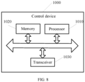
- FIG. 8 is a schematic block diagram of a control device 1000 of an energy storage system according to the embodiment of the present application, As shown in FIG. 8 , the control device 1000 includes a processor 1010 and a memory 1020, wherein the memory 1020 is configured to store instructions, and the processor 1010 is configured to read the instructions and perform the foregoing methods in the embodiments of the present application based on the instructions, wherein the memory 1020 may be an individual device independent of the processor 1010 and may also be integrated into the processor 1010.
- control device 1000 of the energy storage system may also include a transceiver 1030.
- the processor 1010 may control the transceiver 1030 to communicate with other devices.
- the transceiver can send information or data to other devices, or receive information or data sent by other devices.
- the processor may be an integrated circuit chip and has a signal processing capability according to the embodiment of the present application.
- the steps according to the method embodiments above may be completed through an integrated logic circuit of hardware in the processor or instructions in the form of software.
- the above-mentioned processor may be a general-purpose processor, a digital signal processor (DSP), an application specific integrated circuit (ASIC), a field programmable gate array (FPGA) or other programmable logic devices, discrete or transistor logic devices and discrete hardware components.
- the processor may implement or execute the methods, steps and logic block diagrams disclosed according to the embodiments of the present application.
- the general-purpose processor may be a microprocessor or may also be any conventional processor, and so on.
- the steps of the method disclosed in conjunction with the embodiments of the present application may be embodied directly in a hardware decoding processor to be executed and completed or in a combination of hardware and software modules in the decoding processor to be executed and completed.
- the software modules may be located in a mature storage medium of the field, such as RAM, flash memory, ROM, a programmable ROM or an electrically erasable programmable memory and a register.
- the storage medium is located in the memory and the processor reads information in the memory and is in conjunction with hardware thereof to complete the steps of the methods.
- the memory may be a volatile memory or a non-volatile memory, or may include both the volatile memory and the non-volatile memory according to the embodiments of the present application.
- the non-volatile memory may be a read-only memory (ROM), a programmable ROM (PROM), an erasable PROM (EPROM), an electrically EPROM (EEPROM) or a flash memory.
- the volatile memory may be a random-access memory (RAM) and serves as an external cache.
- RAMs such as a static RAM (SRAM), a dynamic RAM (DRAM), a synchronous DRAM (SDRAM), a double-data-rate SDRAM (DDR SDRAM), an enhanced SDRAM (ESDRAM), a synchlink DRAM (SLDRAM) and a direct rambus RAM (DR RAM).
- SRAM static RAM
- DRAM dynamic RAM
- SDRAM synchronous DRAM
- DDR SDRAM double-data-rate SDRAM
- ESDRAM enhanced SDRAM
- SLDRAM synchlink DRAM
- DR RAM direct rambus RAM
- the embodiment of the present application further provides a computer-readable storage medium for storing a computer program.
- the computer-readable storage medium may be applied to the control device of the energy storage system control device according to the embodiment of the present application.
- the computer program is run on a computer to enable the computer to perform corresponding flows implemented by the control device in the methods according to the embodiments of the present application, and for brevity, it is not described here.
- the embodiment of the present application further provides a computer program product which includes computer program instructions.
- the computer program product can be applied to the battery heating control device according to the embodiment of the present application.
- the computer program instructions are run on a computer to enable the computer to perform corresponding flows implemented by the battery heating control device in the methods according to the embodiments of the present application, and for brevity, it is not described here.
- the embodiment of the present application further provides a computer program.
- the computer program can be applied to the battery heating control device according to the embodiment of the present application.
- the computer program is run on a computer to enable the computer to perform corresponding flows implemented by the battery heating control device in the methods according to the embodiments of the present application, and for brevity, it is not described here.
- the disclosed system, devices and methods may be implemented in other manners.
- the device embodiments described above are only illustrative.
- the division of units is only a logical function division. In actual implementation, there may be other division methods.
- multiple units or components may be combined or integrated into another system, or some features may be omitted, or not implemented.
- involved mutual coupling or direct coupling or communication connection may be indirect coupling or communication connection through some interfaces, devices or units or in electrical, mechanical or other forms according to the embodiments of the present application.
- the units described as separate components may or may not be physically separated, and the components displayed as units may or may not be physical units, i.e., they may be located in one place, or they may be distributed on multiple network units. Some or all of the units may be selected according to actual needs to achieve the purposes of the schemes of the embodiments.
- the functional units in the various embodiments of the present application may be integrated into one processing unit, or each unit may exist alone physically, or two or more units may be integrated into one unit.
- the functions, if implemented in the form of software functional units and sold or used as separate products, may be stored in a computer-readable storage medium.
- the technical solution of the present application which is essential or contributes to the prior art, or a part of the technical solution, may be embodied in the form of a computer software product, which is stored in a storage medium, including a plurality of instructions used to enable a computer device (which may be a personal computer, a server, or a network device, etc.) to perform all or part of the steps of the methods described in the embodiments of the present application.
- the foregoing storage medium includes various mediums capable of storing program codes, such as a U disk, a mobile hard disk, a ROM, a RAM, a magnetic disk or an optical disk.
Landscapes
- Engineering & Computer Science (AREA)
- General Chemical & Material Sciences (AREA)
- Manufacturing & Machinery (AREA)
- Chemical & Material Sciences (AREA)
- Chemical Kinetics & Catalysis (AREA)
- Electrochemistry (AREA)
- Automation & Control Theory (AREA)
- Power Engineering (AREA)
- Business, Economics & Management (AREA)
- Transportation (AREA)
- Mechanical Engineering (AREA)
- Economics (AREA)
- Health & Medical Sciences (AREA)
- Sustainable Energy (AREA)
- Sustainable Development (AREA)
- Life Sciences & Earth Sciences (AREA)
- Secondary Cells (AREA)
- General Health & Medical Sciences (AREA)
- Theoretical Computer Science (AREA)
- General Physics & Mathematics (AREA)
- General Business, Economics & Management (AREA)
- Physics & Mathematics (AREA)
- Tourism & Hospitality (AREA)
- Strategic Management (AREA)
- Primary Health Care (AREA)
- Marketing (AREA)
- Human Resources & Organizations (AREA)
- Water Supply & Treatment (AREA)
- Public Health (AREA)
- Charge And Discharge Circuits For Batteries Or The Like (AREA)
Applications Claiming Priority (1)
| Application Number | Priority Date | Filing Date | Title |
|---|---|---|---|
| PCT/CN2022/128752 WO2024092446A1 (zh) | 2022-10-31 | 2022-10-31 | 电池加热的控制方法和控制装置 |
Publications (2)
| Publication Number | Publication Date |
|---|---|
| EP4513625A1 true EP4513625A1 (de) | 2025-02-26 |
| EP4513625A4 EP4513625A4 (de) | 2025-08-27 |
Family
ID=90929315
Family Applications (1)
| Application Number | Title | Priority Date | Filing Date |
|---|---|---|---|
| EP22963765.7A Pending EP4513625A4 (de) | 2022-10-31 | 2022-10-31 | Batterieerwärmungssteuerungsverfahren und steuerungsvorrichtung |
Country Status (4)
| Country | Link |
|---|---|
| US (1) | US20250083567A1 (de) |
| EP (1) | EP4513625A4 (de) |
| CN (1) | CN119032452A (de) |
| WO (1) | WO2024092446A1 (de) |
Families Citing this family (1)
| Publication number | Priority date | Publication date | Assignee | Title |
|---|---|---|---|---|
| CN119833793B (zh) * | 2025-03-17 | 2025-10-24 | 深圳市德兰明海新能源股份有限公司 | 电池加热控制方法、电池管理系统及计算机可读存储介质 |
Family Cites Families (10)
| Publication number | Priority date | Publication date | Assignee | Title |
|---|---|---|---|---|
| CN106608195A (zh) * | 2015-10-23 | 2017-05-03 | 北汽福田汽车股份有限公司 | 电动汽车及其电池加热方法和系统 |
| DE102017210747A1 (de) * | 2017-06-27 | 2018-12-27 | Bayerische Motoren Werke Aktiengesellschaft | Verfahren zum Vorwärmen einer Batterie eines elektrisch betriebenen Kraftfahrzeugs sowie Ladevorrichtung |
| US11495839B2 (en) * | 2017-10-18 | 2022-11-08 | Textron Innovations, Inc. | Internal battery heating |
| KR102375845B1 (ko) * | 2017-11-24 | 2022-03-17 | 주식회사 엘지에너지솔루션 | 배터리 장치 및 배터리 온도 조절방법 |
| EP3530516B1 (de) * | 2018-02-23 | 2022-07-06 | Ningbo Geely Automobile Research & Development Co. Ltd. | Elektrisches batteriesystem |
| CN108736107B (zh) * | 2018-05-22 | 2020-06-23 | 宁德时代新能源科技股份有限公司 | 加热模块和电池组加热方法、加热系统 |
| CN111029667B (zh) * | 2019-11-08 | 2021-05-18 | 华为技术有限公司 | 电池加热系统、电动汽车和车载系统 |
| CN112224092B (zh) * | 2020-10-16 | 2025-03-04 | 广汽本田汽车有限公司 | 一种电电混动系统及其电池温度提升方法 |
| DE102021005316A1 (de) * | 2021-10-26 | 2021-12-16 | Daimler Ag | Batteriesystem für ein Fahrzeug |
| CN115133177B (zh) * | 2022-07-27 | 2023-08-15 | 小米汽车科技有限公司 | 电池加热方法、装置、车辆及介质 |
-
2022
- 2022-10-31 EP EP22963765.7A patent/EP4513625A4/de active Pending
- 2022-10-31 WO PCT/CN2022/128752 patent/WO2024092446A1/zh not_active Ceased
- 2022-10-31 CN CN202280095100.XA patent/CN119032452A/zh active Pending
-
2024
- 2024-11-20 US US18/954,266 patent/US20250083567A1/en active Pending
Also Published As
| Publication number | Publication date |
|---|---|
| EP4513625A4 (de) | 2025-08-27 |
| US20250083567A1 (en) | 2025-03-13 |
| CN119032452A (zh) | 2024-11-26 |
| WO2024092446A1 (zh) | 2024-05-10 |
Similar Documents
| Publication | Publication Date | Title |
|---|---|---|
| EP3444921B1 (de) | Ladesteuerungsvorrichtung und verfahren zum energieeinsparen und zum schnellen zellenausgleich | |
| EP3521098B1 (de) | Motorgetriebenes fahrzeug und steuerungsverfahren für motorgetriebenes fahrzeug | |
| EP3054554A1 (de) | Batteriepack und verfahren zu dessen steuerung | |
| US20210021134A1 (en) | Storage system | |
| US20180345808A1 (en) | Vehicle charging station having degraded energy storage units for charging an incoming vehicle and methods thereof | |
| JP7357700B2 (ja) | 充電方法及び電力変換装置 | |
| KR20220011601A (ko) | 병렬 멀티 팩 모듈의 출력 제어 장치 및 방법 | |
| EP4385801B1 (de) | Entladungssteuerungsverfahren und -vorrichtung, elektronische vorrichtung und speichermedium | |
| CN111071074B (zh) | 一种大数据和bms结合的电动汽车优化充电方法 | |
| CN108790893A (zh) | 一种交流充电桩及充电控制方法 | |
| CN117183823B (zh) | 充电控制方法、充电控制装置及车辆 | |
| EP4492603A2 (de) | Ladesteuerungsverfahren, ladesystem und entsprechende vorrichtung | |
| CN116325286B (zh) | 充放电装置、电池充电的方法和充放电系统 | |
| US20250083567A1 (en) | Battery heating control method and control device | |
| US20250070587A1 (en) | Charging and discharging control method and apparatus, device and storage medium | |
| CN113054288A (zh) | 车辆及其电池加热方法和系统 | |
| WO2024192960A1 (zh) | 功率控制方法、装置、储能系统及非易失性存储介质 | |
| US20250206173A1 (en) | Control device and method for controlling charging of an energy storage device | |
| CN116417711A (zh) | 电池包、电池储能系统、充电控制方法和电池管理系统 | |
| CN109818089A (zh) | 一种电池限流方法及装置 | |
| CN119261675A (zh) | 电池均衡控制方法、装置、均衡控制系统及动力电池系统 | |
| CN104539017B (zh) | 一种动力电池组均衡系统及均衡方法 | |
| CN117941204A (zh) | 电池的充电方法和充电装置 | |
| WO2024060012A1 (zh) | 电池控制方法、系统、装置、设备及存储介质 | |
| CN117183824B (zh) | 充电控制方法、充电控制装置及车辆 |
Legal Events
| Date | Code | Title | Description |
|---|---|---|---|
| STAA | Information on the status of an ep patent application or granted ep patent |
Free format text: STATUS: THE INTERNATIONAL PUBLICATION HAS BEEN MADE |
|
| PUAI | Public reference made under article 153(3) epc to a published international application that has entered the european phase |
Free format text: ORIGINAL CODE: 0009012 |
|
| STAA | Information on the status of an ep patent application or granted ep patent |
Free format text: STATUS: REQUEST FOR EXAMINATION WAS MADE |
|
| 17P | Request for examination filed |
Effective date: 20241121 |
|
| AK | Designated contracting states |
Kind code of ref document: A1 Designated state(s): AL AT BE BG CH CY CZ DE DK EE ES FI FR GB GR HR HU IE IS IT LI LT LU LV MC ME MK MT NL NO PL PT RO RS SE SI SK SM TR |
|
| RAP3 | Party data changed (applicant data changed or rights of an application transferred) |
Owner name: CONTEMPORARY AMPEREX TECHNOLOGY(HONG KONG) LIMITED |
|
| A4 | Supplementary search report drawn up and despatched |
Effective date: 20250725 |
|
| RIC1 | Information provided on ipc code assigned before grant |
Ipc: H01M 10/615 20140101AFI20250721BHEP Ipc: H02J 7/00 20060101ALI20250721BHEP |
|
| DAV | Request for validation of the european patent (deleted) | ||
| DAX | Request for extension of the european patent (deleted) |