EP4513616A2 - Vorrichtung zur kurzschlussprüfung - Google Patents
Vorrichtung zur kurzschlussprüfung Download PDFInfo
- Publication number
- EP4513616A2 EP4513616A2 EP24195235.7A EP24195235A EP4513616A2 EP 4513616 A2 EP4513616 A2 EP 4513616A2 EP 24195235 A EP24195235 A EP 24195235A EP 4513616 A2 EP4513616 A2 EP 4513616A2
- Authority
- EP
- European Patent Office
- Prior art keywords
- electrode assembly
- pressurization
- checking
- short circuits
- unit
- Prior art date
- Legal status (The legal status is an assumption and is not a legal conclusion. Google has not performed a legal analysis and makes no representation as to the accuracy of the status listed.)
- Pending
Links
Images



Classifications
-
- G—PHYSICS
- G01—MEASURING; TESTING
- G01R—MEASURING ELECTRIC VARIABLES; MEASURING MAGNETIC VARIABLES
- G01R1/00—Details of instruments or arrangements of the types included in groups G01R5/00 - G01R13/00 and G01R31/00
- G01R1/02—General constructional details
- G01R1/04—Housings; Supporting members; Arrangements of terminals
-
- G—PHYSICS
- G01—MEASURING; TESTING
- G01R—MEASURING ELECTRIC VARIABLES; MEASURING MAGNETIC VARIABLES
- G01R31/00—Arrangements for testing electric properties; Arrangements for locating electric faults; Arrangements for electrical testing characterised by what is being tested not provided for elsewhere
- G01R31/003—Environmental or reliability tests
-
- G—PHYSICS
- G01—MEASURING; TESTING
- G01R—MEASURING ELECTRIC VARIABLES; MEASURING MAGNETIC VARIABLES
- G01R31/00—Arrangements for testing electric properties; Arrangements for locating electric faults; Arrangements for electrical testing characterised by what is being tested not provided for elsewhere
- G01R31/36—Arrangements for testing, measuring or monitoring the electrical condition of accumulators or electric batteries, e.g. capacity or state of charge [SoC]
- G01R31/378—Arrangements for testing, measuring or monitoring the electrical condition of accumulators or electric batteries, e.g. capacity or state of charge [SoC] specially adapted for the type of battery or accumulator
-
- G—PHYSICS
- G01—MEASURING; TESTING
- G01R—MEASURING ELECTRIC VARIABLES; MEASURING MAGNETIC VARIABLES
- G01R31/00—Arrangements for testing electric properties; Arrangements for locating electric faults; Arrangements for electrical testing characterised by what is being tested not provided for elsewhere
- G01R31/50—Testing of electric apparatus, lines, cables or components for short-circuits, continuity, leakage current or incorrect line connections
- G01R31/52—Testing for short-circuits, leakage current or ground faults
-
- H—ELECTRICITY
- H01—ELECTRIC ELEMENTS
- H01M—PROCESSES OR MEANS, e.g. BATTERIES, FOR THE DIRECT CONVERSION OF CHEMICAL ENERGY INTO ELECTRICAL ENERGY
- H01M10/00—Secondary cells; Manufacture thereof
- H01M10/42—Methods or arrangements for servicing or maintenance of secondary cells or secondary half-cells
- H01M10/4285—Testing apparatus
-
- H—ELECTRICITY
- H01—ELECTRIC ELEMENTS
- H01M—PROCESSES OR MEANS, e.g. BATTERIES, FOR THE DIRECT CONVERSION OF CHEMICAL ENERGY INTO ELECTRICAL ENERGY
- H01M10/00—Secondary cells; Manufacture thereof
- H01M10/42—Methods or arrangements for servicing or maintenance of secondary cells or secondary half-cells
- H01M10/48—Accumulators combined with arrangements for measuring, testing or indicating the condition of cells, e.g. the level or density of the electrolyte
-
- G—PHYSICS
- G01—MEASURING; TESTING
- G01R—MEASURING ELECTRIC VARIABLES; MEASURING MAGNETIC VARIABLES
- G01R31/00—Arrangements for testing electric properties; Arrangements for locating electric faults; Arrangements for electrical testing characterised by what is being tested not provided for elsewhere
- G01R31/36—Arrangements for testing, measuring or monitoring the electrical condition of accumulators or electric batteries, e.g. capacity or state of charge [SoC]
- G01R31/385—Arrangements for measuring battery or accumulator variables
- G01R31/3865—Arrangements for measuring battery or accumulator variables related to manufacture, e.g. testing after manufacture
-
- G—PHYSICS
- G01—MEASURING; TESTING
- G01R—MEASURING ELECTRIC VARIABLES; MEASURING MAGNETIC VARIABLES
- G01R31/00—Arrangements for testing electric properties; Arrangements for locating electric faults; Arrangements for electrical testing characterised by what is being tested not provided for elsewhere
- G01R31/36—Arrangements for testing, measuring or monitoring the electrical condition of accumulators or electric batteries, e.g. capacity or state of charge [SoC]
- G01R31/392—Determining battery ageing or deterioration, e.g. state of health
-
- Y—GENERAL TAGGING OF NEW TECHNOLOGICAL DEVELOPMENTS; GENERAL TAGGING OF CROSS-SECTIONAL TECHNOLOGIES SPANNING OVER SEVERAL SECTIONS OF THE IPC; TECHNICAL SUBJECTS COVERED BY FORMER USPC CROSS-REFERENCE ART COLLECTIONS [XRACs] AND DIGESTS
- Y02—TECHNOLOGIES OR APPLICATIONS FOR MITIGATION OR ADAPTATION AGAINST CLIMATE CHANGE
- Y02E—REDUCTION OF GREENHOUSE GAS [GHG] EMISSIONS, RELATED TO ENERGY GENERATION, TRANSMISSION OR DISTRIBUTION
- Y02E60/00—Enabling technologies; Technologies with a potential or indirect contribution to GHG emissions mitigation
- Y02E60/10—Energy storage using batteries
Definitions
- Embodiments of the present disclosure relate to an apparatus for checking for a short circuit and, more particularly, to an apparatus for checking for short circuits for use in electrode assemblies.
- a secondary battery is a battery that can be repeatedly charged and discharged, and is applied as a power source having output characteristics and stability in eco-friendly electric vehicles, hybrid electric vehicles, energy storage systems (ESS), and the like.
- the secondary battery may include an electrode assembly that includes a positive electrode plate coated with a positive active material, a negative electrode plate coated with an negative active material, and a separator, as well as a battery case (e.g., a pouch exterior material) for accommodating the electrode assembly and an electrolyte.
- an electrode assembly that includes a positive electrode plate coated with a positive active material, a negative electrode plate coated with an negative active material, and a separator, as well as a battery case (e.g., a pouch exterior material) for accommodating the electrode assembly and an electrolyte.
- the electrode assembly Before inserting the electrode assembly into the battery case, the electrode assembly is inspected for a short-circuit occurrence by connecting each probe to a positive electrode tab of the positive electrode plate and to a negative electrode tab of the negative electrode plate respectively, and then by applying a voltage.
- a short circuit occurs when a positive electrode and a negative electrode adjacent to a damaged area of the separator physically come into contact together and a leakage current is detected by a detector provided that the separator between the positive electrode plate and the negative electrode plate is damaged (e.g., folded, tom, punctured, etc.) when voltage is applied.
- the leakage current diverges from the normal range, the electrode assembly is judged to be short-circuited.
- Patent Reference 1 is a method that induces a temporary internal short circuit (short) of the positive electrode plate and the negative electrode plate by applying a surface pressure force to the electrode assembly and then by making the distance between the positive electrode plate and the negative electrode plates as close as possible by means of a pressurization plate.
- a countermeasure may provide the advantage of uniformly pressurizing the entire upper and lower surfaces of the electrode assembly to a predetermined pressure but it may inevitably have limitations in selectively performing partial pressurization on the electrode assembly or measuring electrode assemblies of various sizes.
- Patent Document 1 Korea Patent Application Publication No. 10-2022-0118250
- Embodiments of the present disclosure provide an apparatus for checking for a short circuit, the apparatus which determines whether an electrode assembly is short-circuited while pressurizing the electrode assembly.
- an embodiment of present disclosure is configured to continuously determine whether the electrode assembly is short-circuited.
- the apparatus for checking for short circuits includes a support plate that supports the bottom surface of a center area of an electrode assembly, a pressurization unit that includes a first pressurization member pressurizing a top surface of the center area of the electrode assembly and a second pressurization member pressurizing opposite edge areas of the electrode assembly and a short circuit measurement unit applying voltage to the electrode assembly to check for a short circuit, wherein the pressurization unit is configured to partially pressurize the entire upper and lower surfaces of the electrode assembly per an area.
- the pressurization unit may be separated into first and second pressurization members and may be arranged spaced apart from each other.
- the support plate may include an ejection pin arranged to move up and down.
- the second pressurization member may include an upper pressurization block and a lower pressurization block arranged for reciprocating up and down with opposite edge areas of the electrode assembly placed therebetween.
- the second pressurization member may be positioned at the same vertical line as the edge of the positive electrode plate to pressurize opposite edges of the positive electrode plate of the electrode assembly.
- the apparatus for checking for short circuits includes a transfer unit configured to move a support plate on which the electrode assembly is mounted along a guide rail, a pressurization unit configured to pressurize the entire upper and lower surfaces of the electrode assembly, a short circuit measurement unit configured to determine whether there is a short circuit by applying voltage to the electrode assembly, and a mounting unit configured to position and arrange the pressurization unit along the length direction of the electrode assembly on the transfer unit.
- An embodiment of the present disclosure may separate the electrode assembly into a center area and opposite edge areas that are symmetrically arranged along the length direction of the electrode assembly while being centered around the center area.
- the support plate may be formed in the size and shape capable of supporting the center area of the electrode assembly.
- the support plate may include an ejection pin on the top surface facing the center area of the electrode assembly.
- the pressurization unit may include the first pressurization member for pressurizing the top surface of the center area of the electrode assembly and the second pressurization member for pressurizing opposite edge areas of the electrode assembly.
- the pressurization unit may be separated into first and second pressurization members and may be arranged spaced apart from each other.
- the second pressurization member may include an upper pressurization block and a lower pressurization block arranged for reciprocating up and down with opposite edge areas of the electrode assembly placed therebetween.
- the mounting unit includes a horizontal frame extending orthogonally over the transfer unit, a vertical frame that is installed to be slidable in the length direction of the horizontal frame and is arranged to be coupled with the second pressurization member of the pressurization unit for moving up and down and a driving means that is arranged to be coupled with the horizontal frame in order to enable the first pressurization member of the pressurization unit to move up and down.
- the short circuit measurement unit may be arranged in the second pressurization member to enable to move up and down a first probe and a second probe which contact with the positive electrode tab and the negative electrode tab of the electrode assembly and apply voltage.
- the transfer unit may additionally include a clamping plate for clamping or unclamping the electrode assembly on the support plate.
- the embodiments can reliably check for a short circuit on the electrode assembly while pressurizing the entire upper and lower surfaces of the electrode assembly.
- an embodiment may partially pressurize the entire upper and lower surfaces of the electrode assembly per an area in order to more accurately identify the damaged part of the separator. Further, the embodiments may be universally applied to electrode assemblies of various standards through the above-described partial pressurization on the electrode assembly.
- the embodiments of the present disclosure may provide the advantage of not only enabling total inspection but also shortening the measurement time by continuously performing short circuit measurements of the electrode assembly.
- the embodiments of the present disclosure may reduce unnecessary additional labor and material losses by detecting abnormalities (e.g., short circuits) in advance in the electrode assembly before the process of packaging the electrode assembly in a battery case or activating it after packaging.
- abnormalities e.g., short circuits
- the embodiments relate to an apparatus for checking for short circuits capable of detecting whether a short circuit occurs in an electrode assembly using a pressurization method.
- the apparatus may be preferably configured to check for a short circuit while pressurizing the entire upper and lower surfaces of the electrode assembly.
- the embodiments may detect whether an electrode assembly is short-circuited while guiding the electrode assembly to a subsequent process (e.g., an assembly process in which the electrode assembly is inserted into a battery case together with an electrolyte) after mounting the electrode assembly that includes a positive electrode plate, a negative electrode plate and a separator on the transfer unit.
- a subsequent process e.g., an assembly process in which the electrode assembly is inserted into a battery case together with an electrolyte
- the electrode assembly 100 includes a plurality of positive electrode plates 110, a plurality of negative electrode plates 120, and a separator 130 inserted and placed for providing insulation between the positive electrode plates 110 and the negative electrode plates 120, as shown in FIG. 1 .
- the electrode assembly 100 may be configured to place the separator 130 on the outermost layer, that is, the uppermost layer and the lowermost layer.
- a positive electrode tab 111 may extend outward from the outer edge of the positive electrode plate 110, and a negative electrode tab 121 may extend outward from the outer edge of the negative electrode plate 120.
- the electrode assembly 100 may have the positive electrode tab 111 and the negative electrode tab 121 extending in opposite directions from each other from opposite edges of the length direction of the electrode assembly.
- the length direction of the electrode assembly may mean the withdrawal direction of the electrode tabs 111, 121.
- the electrode assembly may be determined whether the electrode assembly is short-circuited by contacting a first probe and a second probe of the apparatus to check for short circuits, which will be described later, in a state where a plurality of positive electrode tabs and a plurality of negative electrode tabs protruding from the electrode assembly 100 are brought together and are overlapped with the same electrode.
- a plurality of positive electrode tabs and a plurality of negative electrode tabs bond in each bundle form through pre-welding to prevent separation in a state where the positive electrode tabs 111 and the negative electrode tabs 121 may be respectively gathered according to the same electrode, and a bundle of positive electrode tabs and a bundle of negative electrode tabs may contact the first probe and the second probe respectively.
- a check for short circuits may also be provided by welding a plurality of positive electrode tabs 111 to one electrode lead (not shown) and a plurality of negative electrode tabs 121 to the other electrode lead (not shown) via lead welding, and then by contacting the one electrode lead and the other electrode lead of the electrode assembly with the first and second probes respectively.
- the separator 130 has a relatively larger size (e.g., area) than the positive electrode plate 110 and the negative electrode plate 120 to prevent the short circuit of the positive electrode plate 110 and the negative electrode plate 120.
- the charge and discharge efficiency decreases due to the growth of lithium dendrites in secondary batteries, such as lithium secondary batteries.
- a desired level of battery performance effectiveness can be secured by using a large area of the negative electrode plate 120 to suppress the formation of such lithium dendrites. That is, the negative electrode plate 120 may be structured such that the area of the negative electrode plate 120 is relatively larger than the area of the positive electrode plate 110.
- the apparatus for checking for short circuits electrically connects a short circuit measurement unit 30 with the previously described electrode assembly 100.
- the short circuit measurement unit 30 includes a power source (not shown) that applies voltage to the electrode assembly and a current measurement unit (not shown) that checks for leakage current, and is provided with the first probe 30a and the second probe 30b for applying a predetermined voltage from the power source to the electrode assembly 100. As shown, the short circuit measurement unit 30 is connected to the electrode assembly 100 by contacting the first probe 30a with the positive electrode tab 111 and by contacting the second probe 30b with the negative electrode tab 121. Thereby, the short circuit measurement unit 30 may detect the short circuit of the electrode assembly 100 by applying a predetermined voltage to the positive electrode tab 111 and the negative electrode tab 121 of the electrode assembly 100.
- the apparatus for checking for short circuits of the present disclosure may identify failures caused by defects of the separator when the measured leakage current exceeds the normal range.
- the apparatus for checking for short circuits of the present disclosure may detect true defects (actual defects) in the short circuit measurement unit through leakage current as described above.
- the apparatus is configured to detect pseudo defects such as a gap between the separator 130 and the positive electrode plate (or the negative electrode plate), the pseudo defects which are not actual product defects.
- an embodiment of the present disclosure has the feature of applying voltage while keeping the distance between the positive electrode plate, the separator, and the negative electrode plate as close as possible by applying surface pressure to the electrode assembly. That is, voltage is applied while pressurizing the electrode assembly which detects whether the electrode assembly has a short circuit by intentionally inducing a short circuit after physically contacting, the positive electrode plate and the negative electrode plate placed adjacent to the damaged part of the separator, to each other when the separator has a damaged part.
- the apparatus for checking for short circuits may check for a short circuit while pressurizing a top surface and a bottom surface in the thickness direction of an electrode assembly.
- the apparatus for checking for short circuits may partially pressurize the entire top surface and bottom surface of the electrode assembly of the electrode assembly for each area.
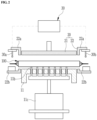
- the apparatus for checking for short circuits may include a support plate 11 that supports the electrode assembly 100, a pressurization unit 20 that pressurizes the entire upper and lower surfaces of the electrode assembly 100, and a short circuit measurement unit 30 that detects an internal short circuit by applying voltage to the electrode assembly 100.
- An embodiment of the present disclosure includes a support plate 11 for supporting the electrode assembly 100.
- the support plate 11 faces and supports one of the flat surfaces of the electrode assembly, for example, the undersurface of the electrode assembly 100.
- the support plate 11 may be formed in a size and shape capable of supporting the center area R1 of the electrode assembly 100. That is, the support plate 11 is arranged to support not opposite edge areas R2 of the electrode assembly 100 but the center area R1.
- the electrode assembly 100 is arranged to symmetrically extend opposite edge areas R2 along the length direction centering on the center area R1 of the electrode assembly 100.
- opposite edge areas R2 refer to the areas adj acent to opposite edges of the positive electrode plate 110 facing the separator 130 and/or the negative electrode plate 120.
- the support plate 11 may support the electrode assembly at a position that does not interfere with opposite edge areas R2 of the electrode assembly 100.
- An embodiment includes a pressurization unit 20 that is configured to partially pressurize the entire upper and lower surfaces of the electrode assembly 100 by dividing them into areas. As shown, the entire upper and lower surfaces of the electrode assembly may be formed in a flat shape.
- the pressurization unit 20 may be composed of the first pressurization member 21 and the second pressurization member 22 which may be separated into the first pressurization member 21 and the second pressurization member 22 that are spaced apart from each other.
- an embodiment may configure the pressurization unit 20 to include a second pressurization member 22, a first pressurization member 21, the second pressurization member 22 sequentially arranged along the length direction of the electrode assembly 100.
- the first pressurization member 21 may pressurize a part corresponding to the center area (R1; see FIG. 1 ) of the electrode assembly 100, and may be specifically positioned for reciprocating up and down over the support plate 11.
- the second pressurization member 22 may pressurize a part corresponding to opposite edge areas (R2; see FIG. 1 ) of the electrode assembly 100 independently of the first pressurization member 21.
- the second pressurization member 22 may be provided at respectively opposite edges of the length direction of the electrode assembly 100.
- the embodiment may effectively pressurize opposite edge areas of the electrode assembly where the possibility of damage to the separator is high, by means of the second pressurization member 22.
- the second pressurization member 22 is enabled to pressurize opposite edges of the positive electrode plate 110 which has a smaller area than the negative electrode plate 120 and the separator 130.
- the second pressurization member 22 includes a pair of pressurization blocks arranged opposite each other with opposite edge areas of the electrode assembly in between, and is configured to include an upper pressurization block 22a reciprocating up and down above the top surface of opposite edge areas of the electrode assembly 100 and a lower pressurization block 22b reciprocating up and down below the bottom surface of opposite edge areas of the electrode assembly 100.
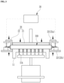
- the upper pressurization block 22a is configured to move upward to pressurize or downward to unpressurize opposite edge areas R2 of the electrode assembly 100 mounted on the support plate 11, and correspondingly the lower pressurization block 22b is configured to move upward to pressurize or downward to unpressurize opposite edge areas R2 of the electrode assembly 100 mounted on the support plate 11.
- the second pressurization member 22 arranges the upper pressurization block 22a and the lower pressurization block 22b on the same vertical line in the thickness direction of the electrode assembly. Specifically, the second pressurization member 22 may be placed on the same vertical line as the edge of the positive electrode plate.
- the first pressurization member, the upper pressurization block, and the lower pressurization block reciprocate up and down using a driving means (not shown).
- the driving means may be a hydraulic cylinder, a pneumatic cylinder, or a drive motor, and any configuration may be used when reciprocating up and down in the thickness direction orthogonal to the length direction of the electrode assembly.
- the first pressurization member 21 and the second pressurization member 22 may be provided with a buffer pad (not shown) on the pressurization part that interfaces with the electrode assembly.
- the second pressurization member 22 may be provided with a buffer pad on the bottom surface of the upper pressurization block 22a and the top surface of the lower pressurization block 22b.
- the buffer pad may prevent damage to the separator 130 in advance while pressurizing the electrode assembly 100 through the first pressurization member and second pressurization member.
- An embodiment of the present disclosure may install a first probe 30a and a second probe 30b on an upper pressurization block 22a of the second pressurization member 22 to easily apply voltage while pressurizing opposite edge areas R2 of the electrode assembly 100 placed adj acent to the positive electrode tab 111 and/or the negative electrode tab 121 using the second pressurization member 22.
- the first probe 30a and the second probe 30b may be spaced apart from each other from the upper pressurization block 22a toward the outer front as shown.
- the ejection pins 11b may be arranged to be capable of moving up and down on the support plate 11 so that the electrode assembly 100 may be easily separated from the support plate 11 after checking for short circuits.
- the support plate 11 includes a plurality of pinholes 1 1a perforated in the thickness direction on a top surface thereof, a plurality of ejection pins 11b respectively inserted through the plurality of pinholes 11a to move up and down, and a hoisting means 11c for hoisting the plurality of the ejection pins 11b.
- the plurality of ejection pins may be installed and fixed to the ejection plate (no reference numeral).
- the ejection plate is coupled to the hoisting means 11c and may move the plurality of ejection pins up and down according to driving of the hoisting means.
- the front end of the ejection pin protrudes from the upper surface of the support plate 11 so that the electrode assembly 100 may be separated from the support plate 11 whereas the ejection pins 11b may move backward into the pinholes 11a while checking for short circuits by pressurizing the electrode assembly using the pressurization unit.
- the electrode assembly may be supported with the ejection pins through the ascending movement of the ejection pins 11b, thereby allowing the electrode assembly to be quickly and reliably taken out into a subsequent process.
- a plurality of ejection pins 11b are spaced apart from each other in the inner area of the support plate 11, and thereby may support the electrode assembly evenly and horizontally.
- a plurality of ejection pins 11b may be arranged in a grid-like pattern at uniform intervals on the top surface of the support plate 11.
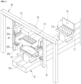
- the apparatus for checking for short circuits is configured to continuously check for a short circuit of an electrode assembly and is configured to detect whether a short circuit occurs while sequentially transferring an electrode assembly to be measured as shown in FIGS. 5 to 6 .
- the apparatus for checking for short circuits includes a transfer unit 10 that sequentially transfers the electrode assembly 100 in a certain direction according to the process sequence, a pressurization unit 20 that pressurizes the entire upper and lower surfaces of the electrode assembly mounted on the transfer unit 10, a short circuit measurement unit 30 that detects an internal short circuit by applying voltage to the electrode assembly (see FIG. 2 ), and a mounting unit 40 that helps to select the position of the pressurization unit 20 to pressurize the entire upper and lower surfaces of the electrode assembly.
- an embodiment of the present disclosure may be configured to enable the electrode assembly 100 to be mounted on the transfer unit 10 and to sequentially enter the pressurization unit 20.
- the transfer unit 10 may be a component member capable of linearly moving an object to be measured in the horizontal direction, and may include a guide rail (no reference sign) extending along the driving direction of the electrode assembly 100 and a support plate 11 driving along the guide rail.
- An embodiment of the present disclosure may position the electrode assembly 100 on the support plate 11 that may slide along the guide rail of the transfer unit 10, and then guide the electrode assembly 100 to be positioned at the pressurization unit 20.
- the transfer unit 10 may include a clamping plate 12 that clamps or unclamps the electrode assembly on the support plate 11.
- the apparatus for checking for short circuits may position the electrode assembly in the pressurization unit 20 as shown in FIG. 5 by means of a transfer unit 10 moving with the mounted electrode assembly 100. Then, the apparatus may check for internal short circuits of the electrode assembly using the short circuit measurement unit 30 (see FIG. 2 ) and then guide to the next facility.
- the support plate 11 may be able to move at a constant speed in the extending direction of the guide rail.
- the support plate 11 is formed in a size and shape capable of supporting the bottom surface of the center area R1 of the electrode assembly 100 and provides a space for installing the clamping plate 12.
- the clamping plate 12 may be formed in a size and shape capable of covering the top surface of the center area of the electrode assembly 100.
- the support plate 11 is provided with a plurality of ejection pins 11b on the top surface facing the electrode assembly 100, more specifically, facing the center area R1 of the electrode assembly.
- the ejection pin 11b is provided to move up and down to separate the electrode assembly 100 from the support plate 11, which is described in detail with reference to FIG. 4 .
- an embodiment of the present disclosure includes a pressurization unit 20 that may selectively perform partial pressurization on the electrode assembly 100 or pressurize the entire upper and lower surfaces of electrode assembly 100 at a time while measuring a short circuit of the electrode assembly.
- the pressurization unit 20 includes the first pressurization member 21 that pressurizes the center area R1 of the electrode assembly 100 and the second pressurization member 22 that pressurizes opposite edge areas R2 of the electrode assembly 100 (see FIG. 1 ).
- the first pressurization member 21 and the second pressurization member 22 may be positioned along the length direction of the electrode assembly by means of the mounting unit 40.
- the mounting unit 40 includes a horizontal frame 41 positioned over the transfer unit 10 that is configured to move with the mounted electrode assembly 100, a vertical frame 42 installed to slide in the length direction of the horizontal frame 41, and a drive means 43 coupled to the horizontal frame 41 to enable the first pressurization member 21 to reciprocate up and down.
- the horizontal frame 41 is arranged in a direction orthogonal to the driving direction of the electrode assembly, and may be arranged orthogonal to the transfer unit.
- an embodiment of the present disclosure may be configured to arrange the first pressurization member 21 to be on the same vertical line as the support plate 11 of the transfer unit 10.
- the first pressurization member 21 is capable of pressurizing or depressurizing the electrode assembly downward and, more specifically, the center area R1 of the electrode assembly 100 using the drive means 43.
- a surface pressure on the center area of the electrode assembly 100 is provided by pressurizing the clamping plate 12 covering the top surface of the center area of the electrode assembly using the first pressurization member 21.
- the clamping plate 12 should be configured to clamp or unclamp the electrode assembly and at the same time be configured to move up and down by the pressurization of the first pressurization member in a state of covering the top surface of the center area of the electrode assembly.
- an embodiment of the present disclosure includes a first slider 42a and a second slider 42b that are coupled to move up and down along the length direction of the vertical frame 42.
- the second pressurization member 22 includes the upper pressurization block 22a and the lower pressurization block 22b arranged opposite to each other and the upper pressurization block 22a is coupled to the first slider 42a whereas the lower pressurization block 22b is coupled to the second slider 42b.
- the upper pressurization block 22a may move down or up to pressurize downward or depressurize the top surfaces of opposite edges of the electrode assembly 100 in dependence on (or urged by) the downward or upward movement of the first slider 42a.
- the lower pressurization block 22b can pressurize upward or depressurize the bottom surfaces of opposite edges of the electrode assembly 100 in dependence on the upward and downward movement of the second slider 42b.
- first and second probes 30a, 30b may be positioned on the outer front side of the upper pressurization block 22a to apply voltage while pressurizing the electrode assembly. Accordingly, the first and second probes 30a, 30b may be arranged to move up and down in conjunction with the upward and downward movement of the upper pressurization block 22a.
- an embodiment of the present disclosure may allow the electrode assembly 100, (which is to be measured) to enter or exit between the upper and lower pressurization blocks 22a and 22b which are spaced apart from each other on the vertical frame 42.
- an embodiment of the present disclosure may reliably pressurize opposite edge areas R2 of the electrode assembly 100 by adjusting the distance between the upper pressurization block 22a and the lower pressurization block 22b on the vertical frame 42 in the direction of contact with each other.
- the first probe 30a and the second probe 30b may contact the positive electrode tab and the negative electrode tab of the electrode assembly 100 and then apply a predetermined voltage.
- the short circuit measurement unit 30 may be electrically connected to the electrode assembly 100 and then determine whether the electrode assembly is defective (for example, short circuits).
- the vertical frame 42 along with the second pressurization member 22 may be arranged in a mirror symmetrical way centering on the drive means 43 in the horizontal frame 41. As a result, this helps to pressurize opposite edge areas R2 of the electrode assembly 100 using the second pressurization member 22.
- the horizontal position of the second pressurization member 22 may change in the length direction of the electrode assembly 100 mounted on the support plate 11 because the vertical frame 42 having the second pressurization member 22 is installed to be slidable on the horizontal frame 41.
- the opposite edge areas R2 of the electrode assembly are aligned between the upper pressurization block 22a and the lower pressurization block 22b of the second pressurization member 22 by changing the horizontal position of the second pressurization member 22 according to the size of the electrode assembly.
Landscapes
- Physics & Mathematics (AREA)
- General Physics & Mathematics (AREA)
- Engineering & Computer Science (AREA)
- Manufacturing & Machinery (AREA)
- Chemical & Material Sciences (AREA)
- Chemical Kinetics & Catalysis (AREA)
- Electrochemistry (AREA)
- General Chemical & Material Sciences (AREA)
- Environmental & Geological Engineering (AREA)
- Secondary Cells (AREA)
- Testing Of Short-Circuits, Discontinuities, Leakage, Or Incorrect Line Connections (AREA)
Applications Claiming Priority (1)
| Application Number | Priority Date | Filing Date | Title |
|---|---|---|---|
| KR1020230109231A KR102687715B1 (ko) | 2023-08-21 | 2023-08-21 | 쇼트 진단장치 |
Publications (2)
| Publication Number | Publication Date |
|---|---|
| EP4513616A2 true EP4513616A2 (de) | 2025-02-26 |
| EP4513616A3 EP4513616A3 (de) | 2025-07-09 |
Family
ID=92172282
Family Applications (1)
| Application Number | Title | Priority Date | Filing Date |
|---|---|---|---|
| EP24195235.7A Pending EP4513616A3 (de) | 2023-08-21 | 2024-08-19 | Vorrichtung zur kurzschlussprüfung |
Country Status (4)
| Country | Link |
|---|---|
| US (1) | US20250067816A1 (de) |
| EP (1) | EP4513616A3 (de) |
| KR (1) | KR102687715B1 (de) |
| CN (1) | CN119493035A (de) |
Citations (1)
| Publication number | Priority date | Publication date | Assignee | Title |
|---|---|---|---|---|
| KR20220118250A (ko) | 2021-02-18 | 2022-08-25 | 주식회사 엘지에너지솔루션 | 모노셀 형태의 분리막 손상 검출 장치 및 방법 |
Family Cites Families (12)
| Publication number | Priority date | Publication date | Assignee | Title |
|---|---|---|---|---|
| DE29608009U1 (de) * | 1996-05-03 | 1996-07-25 | Kara, Jürgen, 96279 Weidhausen | Ausbrechwerkzeug zum Ausbrechen von Stanzabfällen bei der Herstellung von Zuschnitten aus einem Bogen |
| JP4159301B2 (ja) * | 2001-11-28 | 2008-10-01 | 三洋電機株式会社 | 密閉電池 |
| JP4666897B2 (ja) * | 2003-08-25 | 2011-04-06 | パナソニック株式会社 | 電池の製造方法 |
| CN102044466B (zh) * | 2009-10-12 | 2013-03-27 | 北京北方微电子基地设备工艺研究中心有限责任公司 | 一种静电卡盘及其残余电荷的消除方法 |
| KR101736137B1 (ko) * | 2015-11-27 | 2017-05-15 | (주)이티에스 | 이차전지 가압 절연 전압 측정장치 |
| KR102395248B1 (ko) * | 2018-08-09 | 2022-05-04 | 주식회사 엘지에너지솔루션 | 배터리 분리막 손상 검출장치 및 검출방법 |
| KR102408132B1 (ko) * | 2018-11-21 | 2022-06-14 | 주식회사 엘지에너지솔루션 | 지그 가압 방식의 가압 단락 검사 방법 |
| KR102509603B1 (ko) * | 2019-09-18 | 2023-03-10 | 주식회사 엘지에너지솔루션 | 저전압 불량 파우치형 이차전지 셀을 검출하기 위한 가압 단락 검사장치 |
| CN211826396U (zh) * | 2020-01-08 | 2020-10-30 | 天津市捷威动力工业有限公司 | 一种芯包加压短路测试工装 |
| CN214078706U (zh) * | 2020-12-29 | 2021-08-31 | 河源市东润新能源科技有限公司 | 一种软包锂电池的快速冲壳装置 |
| KR102932914B1 (ko) * | 2021-09-30 | 2026-03-03 | 주식회사 엘지에너지솔루션 | 이차전지용 단락 분석 장치 |
| KR102490082B1 (ko) * | 2022-08-02 | 2023-01-18 | 부산대학교 산학협력단 | 내부압 조절이 가능한 전고체 전지 조립체 |
-
2023
- 2023-08-21 KR KR1020230109231A patent/KR102687715B1/ko active Active
-
2024
- 2024-08-13 CN CN202411103634.XA patent/CN119493035A/zh active Pending
- 2024-08-19 EP EP24195235.7A patent/EP4513616A3/de active Pending
- 2024-08-20 US US18/809,328 patent/US20250067816A1/en active Pending
Patent Citations (1)
| Publication number | Priority date | Publication date | Assignee | Title |
|---|---|---|---|---|
| KR20220118250A (ko) | 2021-02-18 | 2022-08-25 | 주식회사 엘지에너지솔루션 | 모노셀 형태의 분리막 손상 검출 장치 및 방법 |
Also Published As
| Publication number | Publication date |
|---|---|
| US20250067816A1 (en) | 2025-02-27 |
| EP4513616A3 (de) | 2025-07-09 |
| CN119493035A (zh) | 2025-02-21 |
| KR102687715B1 (ko) | 2024-07-23 |
Similar Documents
| Publication | Publication Date | Title |
|---|---|---|
| KR102909381B1 (ko) | 배터리 모듈 셀 파우치 절연 저항 검사 시스템 | |
| KR102509603B1 (ko) | 저전압 불량 파우치형 이차전지 셀을 검출하기 위한 가압 단락 검사장치 | |
| CN111226122B (zh) | 多个二次电池单体袋的同时检查设备 | |
| KR20190011565A (ko) | 배터리 팩 검사 장치 및 방법 | |
| KR20180049512A (ko) | 전지셀 제조시스템 | |
| KR102730485B1 (ko) | 배터리 용접 검사장치 | |
| CN114128077B (zh) | 用于对二次电池进行充电和放电的装置 | |
| CN117309284A (zh) | 检测电池单元泄漏的系统和方法 | |
| CN116710766A (zh) | 用于检测低电压电池单体异物位置的设备和使用该设备的分析方法 | |
| KR102620663B1 (ko) | 가압력 보정이 가능한 이차전지 셀 가압 테스트 장치 | |
| KR102638743B1 (ko) | 전극탭 재단장치 | |
| US20250067816A1 (en) | Apparatus for checking for short circuits | |
| TWI873386B (zh) | 用於量測焊條是否正常的焊條測試設備以及使用其之測試方法 | |
| CN116636064B (zh) | 使用tdr检测电池单体内部缺陷的设备和方法 | |
| EP4353402A1 (de) | Vorrichtung und verfahren zum testen des schweisszustands für eine zylindrische sekundärbatterie | |
| CN220428099U (zh) | 芯包夹具 | |
| CN219831136U (zh) | 一种电池测试装置 | |
| CN220127850U (zh) | 一种上板焊接装置 | |
| CN220984608U (zh) | 用于电池单体的挤压短路检查器 | |
| CN210487900U (zh) | 铝基板耐电压测试装置 | |
| US20240302437A1 (en) | Secondary Battery Cell Insulation Test Apparatus and Method Using the Same | |
| KR20240084768A (ko) | 배터리 패키지의 내부 배선 연결성 검사지그 | |
| KR20250072831A (ko) | 전극 조립체 검사 장치 및 이를 이용한 검사 방법 | |
| KR20230058836A (ko) | 용접부 검사장치 및 이를 이용한 용접부 검사방법 | |
| KR20220109372A (ko) | 커패시터 어셈블리 |
Legal Events
| Date | Code | Title | Description |
|---|---|---|---|
| PUAI | Public reference made under article 153(3) epc to a published international application that has entered the european phase |
Free format text: ORIGINAL CODE: 0009012 |
|
| STAA | Information on the status of an ep patent application or granted ep patent |
Free format text: STATUS: REQUEST FOR EXAMINATION WAS MADE |
|
| 17P | Request for examination filed |
Effective date: 20240819 |
|
| AK | Designated contracting states |
Kind code of ref document: A2 Designated state(s): AL AT BE BG CH CY CZ DE DK EE ES FI FR GB GR HR HU IE IS IT LI LT LU LV MC ME MK MT NL NO PL PT RO RS SE SI SK SM TR |
|
| RIC1 | Information provided on ipc code assigned before grant |
Ipc: H01M 10/48 20060101ALI20250319BHEP Ipc: G01R 31/52 20200101ALI20250319BHEP Ipc: G01R 31/385 20190101ALI20250319BHEP Ipc: H01M 10/42 20060101AFI20250319BHEP |
|
| PUAL | Search report despatched |
Free format text: ORIGINAL CODE: 0009013 |
|
| AK | Designated contracting states |
Kind code of ref document: A3 Designated state(s): AL AT BE BG CH CY CZ DE DK EE ES FI FR GB GR HR HU IE IS IT LI LT LU LV MC ME MK MT NL NO PL PT RO RS SE SI SK SM TR |
|
| RIC1 | Information provided on ipc code assigned before grant |
Ipc: H01M 10/48 20060101ALI20250604BHEP Ipc: G01R 31/52 20200101ALI20250604BHEP Ipc: G01R 31/385 20190101ALI20250604BHEP Ipc: H01M 10/42 20060101AFI20250604BHEP |
|
| GRAP | Despatch of communication of intention to grant a patent |
Free format text: ORIGINAL CODE: EPIDOSNIGR1 |
|
| STAA | Information on the status of an ep patent application or granted ep patent |
Free format text: STATUS: GRANT OF PATENT IS INTENDED |
|
| RIC1 | Information provided on ipc code assigned before grant |
Ipc: H01M 10/42 20060101AFI20260331BHEP Ipc: G01R 31/52 20200101ALI20260331BHEP Ipc: H01M 10/48 20060101ALI20260331BHEP Ipc: G01R 31/385 20190101ALN20260331BHEP Ipc: G01R 31/392 20190101ALN20260331BHEP |