EP4513197A2 - Systeme und verfahren zum lesen maschinenlesbarer etiketten auf probenbehältern - Google Patents
Systeme und verfahren zum lesen maschinenlesbarer etiketten auf probenbehältern Download PDFInfo
- Publication number
- EP4513197A2 EP4513197A2 EP25150990.7A EP25150990A EP4513197A2 EP 4513197 A2 EP4513197 A2 EP 4513197A2 EP 25150990 A EP25150990 A EP 25150990A EP 4513197 A2 EP4513197 A2 EP 4513197A2
- Authority
- EP
- European Patent Office
- Prior art keywords
- sample
- sample rack
- rack
- machine
- receptacles
- Prior art date
- Legal status (The legal status is an assumption and is not a legal conclusion. Google has not performed a legal analysis and makes no representation as to the accuracy of the status listed.)
- Pending
Links
Images






Classifications
-
- G—PHYSICS
- G06—COMPUTING OR CALCULATING; COUNTING
- G06K—GRAPHICAL DATA READING; PRESENTATION OF DATA; RECORD CARRIERS; HANDLING RECORD CARRIERS
- G06K7/00—Methods or arrangements for sensing record carriers, e.g. for reading patterns
- G06K7/10—Methods or arrangements for sensing record carriers, e.g. for reading patterns by electromagnetic radiation, e.g. optical sensing; by corpuscular radiation
- G06K7/10544—Methods or arrangements for sensing record carriers, e.g. for reading patterns by electromagnetic radiation, e.g. optical sensing; by corpuscular radiation by scanning of the records by radiation in the optical part of the electromagnetic spectrum
- G06K7/10712—Fixed beam scanning
- G06K7/10722—Photodetector array or CCD scanning
- G06K7/10732—Light sources
-
- G—PHYSICS
- G01—MEASURING; TESTING
- G01N—INVESTIGATING OR ANALYSING MATERIALS BY DETERMINING THEIR CHEMICAL OR PHYSICAL PROPERTIES
- G01N35/00—Automatic analysis not limited to methods or materials provided for in any single one of groups G01N1/00 - G01N33/00; Handling materials therefor
- G01N35/00584—Control arrangements for automatic analysers
- G01N35/00722—Communications; Identification
- G01N35/00732—Identification of carriers, materials or components in automatic analysers
-
- G—PHYSICS
- G01—MEASURING; TESTING
- G01N—INVESTIGATING OR ANALYSING MATERIALS BY DETERMINING THEIR CHEMICAL OR PHYSICAL PROPERTIES
- G01N35/00—Automatic analysis not limited to methods or materials provided for in any single one of groups G01N1/00 - G01N33/00; Handling materials therefor
- G01N35/02—Automatic analysis not limited to methods or materials provided for in any single one of groups G01N1/00 - G01N33/00; Handling materials therefor using a plurality of sample containers moved by a conveyor system past one or more treatment or analysis stations
- G01N35/026—Automatic analysis not limited to methods or materials provided for in any single one of groups G01N1/00 - G01N33/00; Handling materials therefor using a plurality of sample containers moved by a conveyor system past one or more treatment or analysis stations having blocks or racks of reaction cells or cuvettes
-
- G—PHYSICS
- G06—COMPUTING OR CALCULATING; COUNTING
- G06K—GRAPHICAL DATA READING; PRESENTATION OF DATA; RECORD CARRIERS; HANDLING RECORD CARRIERS
- G06K19/00—Record carriers for use with machines and with at least a part designed to carry digital markings
- G06K19/06—Record carriers for use with machines and with at least a part designed to carry digital markings characterised by the kind of the digital marking, e.g. shape, nature, code
- G06K19/06009—Record carriers for use with machines and with at least a part designed to carry digital markings characterised by the kind of the digital marking, e.g. shape, nature, code with optically detectable marking
- G06K19/06018—Record carriers for use with machines and with at least a part designed to carry digital markings characterised by the kind of the digital marking, e.g. shape, nature, code with optically detectable marking one-dimensional coding
- G06K19/06028—Record carriers for use with machines and with at least a part designed to carry digital markings characterised by the kind of the digital marking, e.g. shape, nature, code with optically detectable marking one-dimensional coding using bar codes
-
- G—PHYSICS
- G06—COMPUTING OR CALCULATING; COUNTING
- G06K—GRAPHICAL DATA READING; PRESENTATION OF DATA; RECORD CARRIERS; HANDLING RECORD CARRIERS
- G06K19/00—Record carriers for use with machines and with at least a part designed to carry digital markings
- G06K19/06—Record carriers for use with machines and with at least a part designed to carry digital markings characterised by the kind of the digital marking, e.g. shape, nature, code
- G06K19/06009—Record carriers for use with machines and with at least a part designed to carry digital markings characterised by the kind of the digital marking, e.g. shape, nature, code with optically detectable marking
- G06K19/06037—Record carriers for use with machines and with at least a part designed to carry digital markings characterised by the kind of the digital marking, e.g. shape, nature, code with optically detectable marking multi-dimensional coding
-
- G—PHYSICS
- G06—COMPUTING OR CALCULATING; COUNTING
- G06K—GRAPHICAL DATA READING; PRESENTATION OF DATA; RECORD CARRIERS; HANDLING RECORD CARRIERS
- G06K7/00—Methods or arrangements for sensing record carriers, e.g. for reading patterns
- G06K7/10—Methods or arrangements for sensing record carriers, e.g. for reading patterns by electromagnetic radiation, e.g. optical sensing; by corpuscular radiation
- G06K7/10544—Methods or arrangements for sensing record carriers, e.g. for reading patterns by electromagnetic radiation, e.g. optical sensing; by corpuscular radiation by scanning of the records by radiation in the optical part of the electromagnetic spectrum
- G06K7/10792—Special measures in relation to the object to be scanned
- G06K7/10801—Multidistance reading
- G06K7/10811—Focalisation
-
- G—PHYSICS
- G06—COMPUTING OR CALCULATING; COUNTING
- G06K—GRAPHICAL DATA READING; PRESENTATION OF DATA; RECORD CARRIERS; HANDLING RECORD CARRIERS
- G06K7/00—Methods or arrangements for sensing record carriers, e.g. for reading patterns
- G06K7/10—Methods or arrangements for sensing record carriers, e.g. for reading patterns by electromagnetic radiation, e.g. optical sensing; by corpuscular radiation
- G06K7/10544—Methods or arrangements for sensing record carriers, e.g. for reading patterns by electromagnetic radiation, e.g. optical sensing; by corpuscular radiation by scanning of the records by radiation in the optical part of the electromagnetic spectrum
- G06K7/10821—Methods or arrangements for sensing record carriers, e.g. for reading patterns by electromagnetic radiation, e.g. optical sensing; by corpuscular radiation by scanning of the records by radiation in the optical part of the electromagnetic spectrum further details of bar or optical code scanning devices
- G06K7/10861—Methods or arrangements for sensing record carriers, e.g. for reading patterns by electromagnetic radiation, e.g. optical sensing; by corpuscular radiation by scanning of the records by radiation in the optical part of the electromagnetic spectrum further details of bar or optical code scanning devices sensing of data fields affixed to objects or articles, e.g. coded labels
-
- G—PHYSICS
- G06—COMPUTING OR CALCULATING; COUNTING
- G06K—GRAPHICAL DATA READING; PRESENTATION OF DATA; RECORD CARRIERS; HANDLING RECORD CARRIERS
- G06K7/00—Methods or arrangements for sensing record carriers, e.g. for reading patterns
- G06K7/10—Methods or arrangements for sensing record carriers, e.g. for reading patterns by electromagnetic radiation, e.g. optical sensing; by corpuscular radiation
- G06K7/14—Methods or arrangements for sensing record carriers, e.g. for reading patterns by electromagnetic radiation, e.g. optical sensing; by corpuscular radiation using light without selection of wavelength, e.g. sensing reflected white light
- G06K7/1404—Methods for optical code recognition
- G06K7/1408—Methods for optical code recognition the method being specifically adapted for the type of code
- G06K7/1413—1D bar codes
-
- G—PHYSICS
- G06—COMPUTING OR CALCULATING; COUNTING
- G06K—GRAPHICAL DATA READING; PRESENTATION OF DATA; RECORD CARRIERS; HANDLING RECORD CARRIERS
- G06K7/00—Methods or arrangements for sensing record carriers, e.g. for reading patterns
- G06K7/10—Methods or arrangements for sensing record carriers, e.g. for reading patterns by electromagnetic radiation, e.g. optical sensing; by corpuscular radiation
- G06K7/14—Methods or arrangements for sensing record carriers, e.g. for reading patterns by electromagnetic radiation, e.g. optical sensing; by corpuscular radiation using light without selection of wavelength, e.g. sensing reflected white light
- G06K7/1404—Methods for optical code recognition
- G06K7/1408—Methods for optical code recognition the method being specifically adapted for the type of code
- G06K7/1417—2D bar codes
-
- G—PHYSICS
- G06—COMPUTING OR CALCULATING; COUNTING
- G06K—GRAPHICAL DATA READING; PRESENTATION OF DATA; RECORD CARRIERS; HANDLING RECORD CARRIERS
- G06K7/00—Methods or arrangements for sensing record carriers, e.g. for reading patterns
- G06K7/10—Methods or arrangements for sensing record carriers, e.g. for reading patterns by electromagnetic radiation, e.g. optical sensing; by corpuscular radiation
- G06K7/14—Methods or arrangements for sensing record carriers, e.g. for reading patterns by electromagnetic radiation, e.g. optical sensing; by corpuscular radiation using light without selection of wavelength, e.g. sensing reflected white light
- G06K7/1404—Methods for optical code recognition
- G06K7/1439—Methods for optical code recognition including a method step for retrieval of the optical code
- G06K7/1447—Methods for optical code recognition including a method step for retrieval of the optical code extracting optical codes from image or text carrying said optical code
-
- G—PHYSICS
- G01—MEASURING; TESTING
- G01N—INVESTIGATING OR ANALYSING MATERIALS BY DETERMINING THEIR CHEMICAL OR PHYSICAL PROPERTIES
- G01N35/00—Automatic analysis not limited to methods or materials provided for in any single one of groups G01N1/00 - G01N33/00; Handling materials therefor
- G01N35/00584—Control arrangements for automatic analysers
- G01N35/00722—Communications; Identification
- G01N35/00732—Identification of carriers, materials or components in automatic analysers
- G01N2035/00742—Type of codes
- G01N2035/00752—Type of codes bar codes
-
- G—PHYSICS
- G01—MEASURING; TESTING
- G01N—INVESTIGATING OR ANALYSING MATERIALS BY DETERMINING THEIR CHEMICAL OR PHYSICAL PROPERTIES
- G01N35/00—Automatic analysis not limited to methods or materials provided for in any single one of groups G01N1/00 - G01N33/00; Handling materials therefor
- G01N35/00584—Control arrangements for automatic analysers
- G01N35/00722—Communications; Identification
- G01N35/00732—Identification of carriers, materials or components in automatic analysers
- G01N2035/00792—Type of components bearing the codes, other than sample carriers
- G01N2035/00801—Holders for sample carriers, e.g. trays, caroussel, racks
-
- G—PHYSICS
- G01—MEASURING; TESTING
- G01N—INVESTIGATING OR ANALYSING MATERIALS BY DETERMINING THEIR CHEMICAL OR PHYSICAL PROPERTIES
- G01N35/00—Automatic analysis not limited to methods or materials provided for in any single one of groups G01N1/00 - G01N33/00; Handling materials therefor
- G01N35/00584—Control arrangements for automatic analysers
- G01N35/00722—Communications; Identification
- G01N35/00732—Identification of carriers, materials or components in automatic analysers
- G01N2035/00821—Identification of carriers, materials or components in automatic analysers nature of coded information
- G01N2035/00831—Identification of carriers, materials or components in automatic analysers nature of coded information identification of the sample, e.g. patient identity, place of sampling
-
- G—PHYSICS
- G01—MEASURING; TESTING
- G01N—INVESTIGATING OR ANALYSING MATERIALS BY DETERMINING THEIR CHEMICAL OR PHYSICAL PROPERTIES
- G01N35/00—Automatic analysis not limited to methods or materials provided for in any single one of groups G01N1/00 - G01N33/00; Handling materials therefor
- G01N35/00584—Control arrangements for automatic analysers
- G01N35/00722—Communications; Identification
- G01N35/00732—Identification of carriers, materials or components in automatic analysers
- G01N2035/00821—Identification of carriers, materials or components in automatic analysers nature of coded information
- G01N2035/00851—Identification of carriers, materials or components in automatic analysers nature of coded information process control parameters
-
- G—PHYSICS
- G01—MEASURING; TESTING
- G01N—INVESTIGATING OR ANALYSING MATERIALS BY DETERMINING THEIR CHEMICAL OR PHYSICAL PROPERTIES
- G01N35/00—Automatic analysis not limited to methods or materials provided for in any single one of groups G01N1/00 - G01N33/00; Handling materials therefor
- G01N35/02—Automatic analysis not limited to methods or materials provided for in any single one of groups G01N1/00 - G01N33/00; Handling materials therefor using a plurality of sample containers moved by a conveyor system past one or more treatment or analysis stations
- G01N35/04—Details of the conveyor system
- G01N2035/0401—Sample carriers, cuvettes or reaction vessels
- G01N2035/0412—Block or rack elements with a single row of samples
- G01N2035/0413—Block or rack elements with a single row of samples moving in one dimension
-
- G—PHYSICS
- G01—MEASURING; TESTING
- G01N—INVESTIGATING OR ANALYSING MATERIALS BY DETERMINING THEIR CHEMICAL OR PHYSICAL PROPERTIES
- G01N35/00—Automatic analysis not limited to methods or materials provided for in any single one of groups G01N1/00 - G01N33/00; Handling materials therefor
- G01N35/02—Automatic analysis not limited to methods or materials provided for in any single one of groups G01N1/00 - G01N33/00; Handling materials therefor using a plurality of sample containers moved by a conveyor system past one or more treatment or analysis stations
- G01N35/04—Details of the conveyor system
- G01N2035/0474—Details of actuating means for conveyors or pipettes
- G01N2035/0491—Position sensing, encoding; closed-loop control
- G01N2035/0493—Locating samples; identifying different tube sizes
Definitions
- Embodiments of this disclosure are directed to systems and methods for reading machine-readable labels on sample receptacles, for example, sample receptacles used to perform assays.
- An analyzer system can perform assays on fluid sample material.
- the analyzer system can be configured to perform multi-step analytical processes (for example, a nucleic acid test (NAT) designed to detect microbe, such as a virus or a bacterium) that involve adding substances (e.g., fluids), such as samples, solid supports, buffers, oil, primers, polymerases, nucleotides, labels, probes, or other reaction fluids, to and/or removing substances from receptacles, agitating receptacles to mix the contents thereof, maintaining and/or altering the temperature of the contents of the receptacles, heating or chilling the contents of the receptacles, altering the concentration of one or more content components of the receptacles, separating or isolating constituent components of the contents of the receptacles, detecting an electromagnetic signal emission (for example, light) from the contents of the receptacles, deactivating or halting
- substances e.
- the analyzer system can be automated to perform the desired analytical process. Accordingly, the analyzer system can automatically identify the contents of a sample receptacle and the assay to perform. For example, the analyzer system can read labels, for example, a barcode, on the sample receptacle to identify the contents of the sample receptacle and the assay to perform.
- labels for example, a barcode
- a method of reading machine-readable labels on sample receptacles includes moving, between a first position and a second position in a housing, a sample rack configured to hold a plurality of sample receptacles. Each sample receptacle has a machine-readable label. The method also includes measuring an absolute position of the sample rack as the sample rack moves between the first position and the second position, and acquiring an image of the machine-readable label of each sample receptacle of the plurality of sample receptacles as the sample rack moves from the first position to the second position. Further, the method includes decoding the acquired image of the machine-readable label of each sample receptacle of the plurality of sample receptacles.
- the method also includes associating a decoded acquired image of the machine-readable label of each sample receptacle of the plurality of sample receptacles with the corresponding sample receptacle based on a measured absolute position of the sample rack when the image of the machine-readable label was acquired.
- the machine-readable label can be a barcode.
- the barcode can be a one- or two-dimensional barcode.
- the barcode contains information that associates a sample within the sample receptacle to a patient.
- Moving the sample rack can include manually moving the sample rack or automatically moving the sample rack. In some embodiments, the sample rack is moved at a high rate of speed.
- the second position in the housing is a fully inserted position, and decoding the acquired image occurs after the sample rack is moved to the second position.
- measuring the absolute position of the sample rack uses a reader, and acquiring an image of the machine-readable label uses the reader.
- measuring the absolute position of the sample rack uses a reader, and acquiring an image of the machine-readable label uses a second reader separate from the first reader.
- acquiring the image of the machine-readable label comprises using a reader.
- a method of reading machine-readable labels on sample receptacles includes moving, between a first position and a second position in a housing, a sample rack configured to hold a plurality of sample receptacles. Each sample receptacle has a machine-readable label. The method also includes activating a label reader when the sample rack is at each of a plurality of predetermined positions between the first position and the second position to read the machine-readable label of each sample receptacle of the plurality of sample receptacles as the sample rack moves from the first position to the second position. In some embodiments, the method also includes activating a light source when the sample rack is at each of the plurality of predetermined positions.
- moving the sample rack comprises manually moving the sample rack. In some embodiments, moving the sample rack comprises automatically moving the sample rack. In some embodiments, method also includes measuring a position of the sample rack as the sample rack moves between the first position and the second position. Measuring the position of the sample rack can include using a sensor operably coupled to an indicator on the sample rack.
- the indicator can include at least one of the group consisting of: a recess, a protrusion, an optically reflective element, a magnetic element, and a capacitive element.
- the machine-readable label can be a one- or two-dimensional barcode.
- the machine-readable label can be a two-dimensional barcode that contains information that associates a sample within the sample receptacle to a patient.
- a method of reading machine-readable labels on sample receptacles includes moving, between a first position and a second position in a housing, a sample rack configured to hold a plurality of sample receptacles. Each sample receptacle has a machine-readable label. The method also includes measuring positions of the sample rack as the sample rack moves between the first position and the second position. Further, the method includes reading the machine-readable label of each sample receptacle of the plurality of sample receptacles as the sample rack moves from the first position to the second position. And the method includes decoding a read machine-readable label of each sample receptacle of the plurality of sample receptacles.
- the method also includes associating a decoded machine-readable label of each sample receptacle of the plurality of sample receptacles with the corresponding receptacle based on a measured position of the sample rack when the machine-readable label was read.
- moving the sample rack includes manually moving the sample rack.
- moving the sample rack includes automatically moving the sample rack.
- the machine-readable label contains information that associates a sample within the sample receptacle to a patient.
- the second position in the housing is a fully inserted position, and decoding the machine-readable label occurs after the sample rack is moved to the second position.
- the machine-readable label is a barcode.
- the barcode is a one- or two-dimensional barcode.
- a method for reading machine-readable labels on sample receptacles includes reading, at a first location, a machine-readable label of each sample receptacle of a plurality of sample receptacles with a first label reader.
- the plurality of sample receptacles are held by a sample rack having a rack-identifying machine-readable label.
- the method also includes moving the rack from the first location to a separate second location and sensing, at the second location, a rack identifier on the sample rack with a sensor separate from the first label reader.
- the method includes associating a sensed rack identifier with a read machine-readable label of each sample receptacle of a plurality of sample receptacles.
- the rack identifier is a machine-readable label
- the sensor is a second label reader.
- the rack identifier is an RFID tag
- the sensor is an RFID reader.
- the method also includes acquiring location data identifying the second location to which the sample rack was moved.
- the machine-readable label of each sample receptacle of a plurality of sample receptacles is a two-dimensional barcode. The two-dimensional barcode can contain information that associates a sample within the sample receptacle to a patient.
- the method also includes determining whether a time period during which the sample rack was moved from the first location to the separate second location exceeds a predetermined time period threshold.
- reading the machine-readable label of each sample receptacle of a plurality of sample receptacles occurs while the sample rack is moved between a first position and a second position at the first location.
- the method also includes measuring a position of the sample rack as the sample rack moves between the first position and the second position; acquiring an image of the machine-readable label of each sample receptacle of the plurality of sample receptacles as the sample rack moves from the first position to the second position; decoding the acquired image of the machine-readable label of each sample receptacle of the plurality of sample receptacles; and associating a decoded acquired image of the machine-readable label of each sample receptacle of the plurality of sample receptacles with the corresponding sample receptacle based on a measured position of the sample rack when the image of the machine-readable label was acquired.
- a method of reading machine-readable labels on sample receptacles includes moving, between a first position and a second position along a first lane in a housing, a first sample rack configured to hold a first plurality of sample receptacles each having a machine-readable label. The method also includes moving a camera to focus the camera at a point along the first lane, and reading the machine-readable label of each sample receptacle of the first plurality of sample receptacles of the first sample rack as the first sample rack moves from the first position to the second position.
- the method also includes moving, between a first position and a second position along a second first lane different than the first lane in the housing, a second sample rack configured to hold a second plurality of sample receptacles each having a machine-readable label. Further, the method includes moving the camera to focus the camera at a point along the second lane and reading the machine-readable label of each sample receptacle of the second plurality of sample receptacles of the second sample rack as the second sample rack moves from the first position to the second position.
- the camera is a fixed focal length camera. In other embodiments, the camera is a variable focal length camera.
- moving the first sample rack includes manually moving the first sample rack, and moving the second sample rack includes manually moving the second sample rack. In other embodiments, moving the first sample rack includes automatically moving the first sample rack, and moving the second sample rack includes automatically moving the second sample rack. In some embodiments, the method also includes activating a light source simultaneously with reading the machine-readable label of each sample receptacle of the first plurality of sample receptacles of the first sample rack as the first sample rack moves from the first position to the second position, and activating the light source simultaneously with reading the machine-readable label of each sample receptacle of the second plurality of sample receptacles of the second sample rack as the second sample rack moves from the first position to the second position.
- the method includes reading a rack-identifying machine-readable label on each of the first and second sample racks.
- the machine-readable label can be a two-dimensional barcode that, in some embodiments, contains information that associates a sample within the sample receptacle to a patient.
- a system for reading machine-readable labels on sample receptacles includes a housing and a camera configured to acquire an image of a machine-readable label of each sample receptacle of a plurality of sample receptacles as a sample rack configured to hold the plurality of sample receptacles moves between a first position and a second position within the housing.
- the system also includes a processing and control unit configured to decode an acquired image of the machine-readable label of each sample receptacle of a plurality of sample receptacles.
- the processing and control unit is also configured to associate a decoded acquired image of the machine-readable label of each sample receptacle of the plurality of sample receptacles with the corresponding receptacle based on a measured absolute position of the sample rack when the image of the machine-readable label was acquired.
- the system also includes position sensor configured to measure an absolute position of the sample rack.
- the position sensor is configured to measure the absolute position of the sample rack using a position indicator on the sample rack.
- the position sensor can be a plurality of optic read sensors, a plurality of magnetic read sensors, a plurality of capacitive read sensors, a plurality of gears, or a plurality of friction wheels.
- the camera is configured to acquire an image of an optical encoder strip on the sample rack
- the processing and control unit is configured to decode an acquired image of the optical encoder strip to measure the absolute position of the sample rack and configured to associate a measured absolute position of the sample rack with an acquired image of the machine-readable label of each sample receptacle of a plurality of sample receptacles.
- the system is configured such that the sample rack is manually moved between the first position and the second position. In some embodiments, the system is configured such that the sample rack is automatically moved between the first position and the second position.
- the camera can be a line scan camera or an area scan camera.
- the machine-readable label can be a two-dimensional barcode that, in some embodiments, contains information that associates a sample within the sample receptacle to a patient.
- the camera can be disposed within the housing or coupled to the housing.
- the processing and control unit can be disposed within the housing or coupled to the housing.
- a system for reading machine-readable labels on sample receptacles includes a housing and a label reader configured to read a machine-readable label of each sample receptacle of a plurality of sample receptacles held by a sample rack that moves between a first position and a second position within the housing.
- the system also includes a processing and control unit configured to activate the label reader when the sample rack is at each of a plurality of predetermined positions between the first position and the second position to read the machine-readable label of each sample receptacle of the plurality of sample receptacles as the sample rack moves from the first position to the second position.
- the label reader is further configured to read a machine-readable rack identifier label on the sample rack.
- the system also includes a sensor operatively coupled to an RFID tag on the sample rack.
- the system also includes a sensor operatively coupled to a position indicator on the sample rack to determine a position of the sample rack between the first position and the second position.
- the position sensor can be a plurality of optic read sensors, a plurality of magnetic read sensors, a plurality of capacitive read sensors, a plurality of gears, or a plurality of friction wheels.
- the processing and control unit can be configured to activate a light source when the sample rack is at each of the plurality of predetermined positions.
- the system can be configured such that the sample rack is manually moved between the first position and the second position.
- the system can also be configured such that the sample rack is automatically moved between the first position and the second position.
- the label reader is disposed within the housing or coupled to the housing.
- the processing and control unit is disposed within the housing or coupled to the housing.
- a system for reading machine-readable labels on sample receptacles includes a sample rack having a rack identifier and configured to hold a plurality of sample receptacles, each having a machine-readable label.
- the system also includes a first location configured to receive the sample rack, and a sensor configured to read the rack identifier when the sample rack is at the first location.
- the system also includes a second location configured to receive the sample rack, and a first label reader, separate from the sensor, configured to read the machine-readable label of each sample receptacle of the plurality of sample receptacles when the rack is at the second location.
- the rack identifier is a machine-readable label
- the sensor is a second label reader.
- the rack identifier is an RFID tag
- the sensor is an RFID reader.
- the machine-readable label is a two-dimensional barcode that, in some embodiments, contains information that associates a sample within the sample receptacle to a patient.
- the system can be configured such that the sample rack is manually moved between a first position and a second position when at the first location.
- the system can also be configured such that the sample rack is automatically moved between a first position and a second position when at the first location.
- the processing and control unit is also configured to associate the decoded two-dimensional machine-readable label of each sample receptacle of the plurality of sample receptacles with the corresponding receptacle based on a measured position of the sample rack when the two-dimensional machine-readable label was read.
- the system is configured such that the sample rack is manually moved between the first position and the second position. In other embodiments, the system is configured such that the sample rack is automatically moved between the first position and the second position.
- the reader is disposed within the housing or coupled to the housing. In some embodiments, the processing and control unit is disposed within the housing or coupled to the housing.
- a system for reading machine-readable labels on sample receptacles includes a housing defining at least a first lane and a second lane. Each lane is configured to receive a sample rack adapted to hold a plurality of sample receptacles, and each of the sample receptacles has a machine-readable label.
- the system also includes a camera configured to move to a first position that focuses the camera at a first position along the first lane and to a second position that focuses the camera at a second position along the second lane second lane.
- the camera is configured to acquire an image of the machine-readable label of each sample receptacle of a first plurality of sample receptacles of a first sample rack moving along the first lane.
- the camera is also configured to acquire an image of the machine-readable label of each sample receptacle of a second plurality of sample receptacles of a second sample rack moving along the second lane.
- the camera is a fixed focal length camera. In other embodiments, the camera is a variable focal length camera. In some embodiments, the camera is configured to acquire images of the machine-readable label of each sample receptacle of a plurality of sample receptacles of sample racks being manually moved along the first lane and the second lane.
- the camera is configured to acquire images of the machine-readable label of each sample receptacle of a plurality of sample receptacles of sample racks being automatically moved along the first lane and the second lane.
- the machine-readable label is a two-dimensional barcode that, in some embodiments, contains information that associates a sample within the sample receptacle to a patient.
- the camera comprises a CCD camera or a CMOS camera.
- the system also includes a light source configured to illuminate the machine-readable label of each sample receptacle within the housing.
- the system includes a moveable stage to which the camera and the light source are coupled.
- the camera is configured to move along a lane parallel to the first and second lane.
- the system also includes a mirror positioned along an optical path between the camera and the first position on the first lane and the second position on the second lane.
- a system can include a housing (for example, a sample bay housing) configured to receive a plurality of sample racks along a plurality of lanes. Each sample rack holds sample receptacles having two-dimensional barcodes.
- the system includes a reader, for example, a laser barcode scanner or a camera, that reads the two-dimensional barcode.
- the system also includes a processing and control unit that decodes the read two-dimensional barcodes to obtain information from the barcodes and associate the information with a corresponding sample receptacle.
- a processing and control unit that decodes the read two-dimensional barcodes to obtain information from the barcodes and associate the information with a corresponding sample receptacle.
- Such systems and methods for reading two-dimensional barcodes on sample receptacles can be used for performing assays on fluid sample material and for identifying the contents of the sample receptacles, for example, patient information (e.g., patient identification numbers).
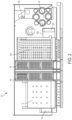
- FIGS. 1 and 2 illustrate perspective and plan views, respectively, of an exemplary analyzer system 10 for performing assays on fluid sample material.
- analyzer system 10 is configured to perform a multi-step analytical process (for example, a nucleic acid test (NAT) designed to detect microbe, such as a virus or a bacterium) or other chemical, biochemical or biological processes.
- a multi-step analytical process for example, a nucleic acid test (NAT) designed to detect microbe, such as a virus or a bacterium
- NAT nucleic acid test
- Exemplary process steps include, for example, adding substances (e.g., fluids), such as samples, solid supports, buffers, oil, primers, polymerases, nucleotides, labels, probes, or other reaction fluids, to and/or removing substances from receptacles, agitating receptacles to mix the contents thereof, maintaining and/or altering the temperature of the contents of the receptacles (for example, using heated incubators configured to receive a plurality of reaction receptacles and maintain the receptacles in an elevated temperature environment), heating or chilling the contents of the receptacles (for example, using temperature ramping stations configured raise the temperature of the contents of reaction receptacles or chilling modules configured to reduce the temperature of the contents of the receptacles), altering the concentration of one or more content components of the receptacles, separating or isolating constituent components of the contents of the receptacles (for example, using magnetic separation wash stations configured to isolate
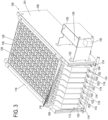
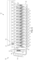
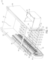
- FIGS. 3 and 4 illustrate front and rear perspective views, respectively, of a sample bay 100 according to an embodiment.
- Sample bay 100 is configured to receive a plurality of sample racks 102 along defined lanes within sample bay 100.
- Sample racks 102 support a plurality of sample receptacles (not shown in FIGS. 3 and 4 ) that contain fluid sample material.
- sample bay 100 is configured to receive eight sample racks 102 that move along defined lanes within sample bay 100. In other embodiments, sample bay 100 is configured to receive less than or more than eight sample racks 102.
- reader 124 is configured to read two-dimensional barcode labels (and in some embodiments, one-dimensional barcode labels or both one- and two-dimensional barcode labels) on sample racks 102, including machine-readable labels on receptacles held by sample racks 102.
- reader 124 is disposed outside of housing 101 and spaced was from opening 122 as shown in FIGS. 3 , 4 , and 11-16 . In some embodiments (not shown), reader 124 is disposed outside of housing 101 and directly adjacent opening 122. In other embodiments (not shown), reader 124 is disposed within housing 101.
- sample bay 100 including reader 124 and its data processing system, are configured as described in the various embodiments disclosed in International Application No. PCT/US2010/035146, filed on May 17, 2010 , and in U.S. Patent Application Publication No. 2012/0261469, published on October 18, 2012 , both of which are incorporated by reference in this application.
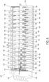
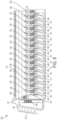
- FIGS. 5-10 illustrate various embodiments of sample rack 102.
- sample rack 102 is configured to hold a plurality of sample receptacles 128.
- sample rack 102 is configured to hold 15 sample receptacles 128.
- sample rack 102 includes a base 129 that defines a plurality of pockets 130 for closely receiving sample receptacles 128. Pockets 130 can be separated from each other by a vertical dividing wall in some embodiments.
- sample receptacles 128 are tubular containers, for example, test tubes.
- sample rack 102 includes a resilient element, such as a spring clip 131, for each pocket 130.
- Spring clip 131 comprises a bent element (made of, e.g., spring stainless steel) with one portion attached to a dividing wall defining pocket 130 and another portion extending at an acute angle into pocket 130.
- Each spring clip 131 can accommodate sample receptacles 128 of varying sizes.
- a sample receptacle 128 is held in a relatively secure, fixed position within pocket 130 by means of spring clip 131 which urges sample receptacle 128 toward a dividing wall forming one side of pocket 130.
- sample rack 102 includes a handle 132 configured to allow a user to grasp and manually move sample rack 102 in some embodiments. For example, a user can grasp handle 132 to insert or remove sample rack 102 from housing 101 of sample bay 100.
- handle 132 defines an opening 134 that is configured to allow a user's fingers to pass through.
- opening 134 allows the optical path 150 (see FIGS. 11 and 12 ) of reader 124 to pass through sample rack 102 to read a machine-readable label on a sample rack 102 positioned on the other side of opening 134 from reader 124.
- sample rack 102 includes a rack identifier 136 that provides unique rack-identifying information, for example, a rack identification number.
- rack identifier 136 is an RFID tag.
- sample bay 100 includes an RFID reader configured to interrogate the RFID tag when sample rack 102 is within sample bay 100.
- rack identifier 136 is a machine readable label, for example, a one- (as shown in FIG. 5 ) or two-dimensional barcode.
- reader 124 is a label reader configured to read rack identifier 136.
- Rack identifier 136 can be positioned near handle 132 of sample rack 102, as shown in FIG. 5 .
- sample rack 102 includes a pocket identifier 138, for example, a one- (as shown in FIG. 5 ) or two-dimensional barcode that provides unique pocket identifying information for each pocket 130 of sample rack 102.
- pocket identifier 138 indicates the position of a corresponding pocket 130 on sample rack 102 and, thus, the position of a sample receptacle 128 in the corresponding pocket 130 on sample rack 102.
- pocket identifiers 138 are located on the outer surface of dividing walls that separate adjacent pockets 130 from each other.
- pocket identifier 138 includes an alphanumeric identifier, for example, "A,” "B,” “C,” etc., that uniquely identifies each pocket 130.
- sample rack 102 includes an empty-recess identifier 140, for example, a machine-readable label such as a one- (as shown in FIG. 5 ) or two-dimensional barcode, that is used to identify pockets 130 that do not contain a sample receptacle 128.
- empty-recess identifier 140 is located within each pocket 130.
- sample rack 102 also includes a cover 146 configured to fit over the top of sample receptacles 128 held within pockets 130 of sample rack 102.
- cover 146 is transparent or translucent such that the contents of pockets 130 can be observed without removing cover 146.
- Cover 146 is configured to be releasably secured to base 129 of sample rack 102. In other embodiments, sample rack 102 does not include a cover 146.
- cover 146 includes a machine-readable label 137 such as a one- (as shown in FIG. 5 ) or two-dimensional barcode.
- Label 137 is configured to be used to determine whether cover 146 is coupled to base 129 and/or positioned properly relative to base 129.
- each sample receptacle 128 within sample rack 102 includes a label 142 in some embodiments.
- labels 142 include machine-readable labels 144, for example, one- or two-dimensional (as shown in FIG. 5 ) barcodes.
- Two-dimensional barcodes express information in two directions, for example, in the horizontal and vertical directions, and include stacked barcodes and matrix barcodes.
- Two-dimensional barcodes include, for example, Aztec codes, PDF417 codes, MaxiCodes, Codablock codes, Data Matrix codes, and QR codes. Two-dimensional barcodes can improve decoding accuracy and increase the amount of information contained within the barcode relative to a one-dimensional barcode.
- two-dimensional barcode labels 144 have features as small as 0.2 mm x 0.2 mm.
- reader 124 is configured to accurately read two-dimensional barcode labels 144 when sample rack 102 is moving at high speeds, for example, speeds greater than 100 mm/ sec, for example, speeds greater than 300 mm/sec, 500 mm/sec, 600 mm/sec, and 1000 mm/sec.
- sample bay 100 is configured to automatically move sample rack 102 within housing 101 of sample bay 100.
- sample bay 100 can include an automated actuator that moves sample racks 102 within housing 101 of sample bay 100 to a fully inserted position.
- sample rack 102 is automatically moved within housing 101 at a known, constant speed.
- sample bay 100 To place a sample rack 102 within housing 101 of sample bay 100, a user aligns guide track 156 with guides 114 on base 104. The user then moves sample rack 102 in a direction 148 (as shown in FIG. 11 ) along a lane defined by guides 114 from a first, initial position to a second, fully inserted position within housing 101 of sample bay 100.
- sample bay 100 includes sensors that detect the presence of sample rack 102 and whether sample rack 102 is fully inserted into the sample bay 100. As best seen in FIG. 5 , sample receptacles 128 are placed in sample rack 102 such that labels 142 are aligned with the openings defined by the dividing walls that separate adjacent pockets 130 from each other.
- labels 142 are visible to reader 124 through opening 122 defined in side wall 108 of housing 101.
- reader 124 can read labels 142 on each sample receptacle 128 on sample rack 102.
- sample bay 100 includes a position measurement system that measures the position of sample rack 102 within housing 101.
- the position measurement system is configured to determine the absolute position of sample rack 102.
- absolute position means the exact position of sample rack 102 within sample bay 100.
- incrementmental position means an incremental range of positions that sample rack 102 could be within sample bay 100 from a reference point.
- sample rack 102 includes an absolute position indicator 158.
- position indicator 158 extends along a length of sample rack 102 (for example, along base 129 or cover 146) that overlaps with pockets 130.
- position indicator 158 extends along a length of cover 146 that overlaps all pockets 130 defined in sample rack 102 in some embodiments. In FIG. 8 , position indicator 158 is located on a side surface 161 of cover 146, and in FIG. 10 , position indicator 158 is positioned on a top surface 162 of cover 146.
- the position measurement system includes a position sensor that operatively corresponds to the type of position indicator 158 coupled to sample rack 102.
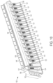
- the measurement system can include optical or magnetic read sensors 164 coupled to housing 101 and configured to read the optical encoder strip or the magnetic encoder strip as sample rack 102 passes near (for example, over, under, or to the side of) optical or magnetic read sensors 164 as shown in FIGS. 13 and 14 .
- read sensors 164 are positioned on base 104 as shown in FIG 13 when position indicator 158 is located on a bottom surface of sample rack 102. As shown in FIGS.
- each lane within housing 101 of sample bay 100 includes optical or magnetic read sensors 164 configured to sense a position indicator 158 on a sample rack 102 that is moving along the corresponding lane.
- the measurement system can include optical or magnetic read sensors 164 positioned on top panel 116 that are configured to read an optical encoder strip or a magnetic encoder strip 158 as sample rack 102 passes sensors 164, as shown in FIG. 14 .
- the measurement system can include through-beam sensors 165 that generate a beam aligned with position indicator 158 to read optical encoder strip 158.
- the measurement system can include a position sensor that includes a gear 166 which engages the plurality of corresponding recesses formed on sample rack 102, as shown in FIG. 15 . As sample rack 102 moves between positions along the lane within housing 101 of sample bay 100, gear 166 rotates to encode the absolute position of sample rack 102.
- the measurement system can include a position sensor that includes a friction wheel, similar to gear 166 shown in FIG. 15 , except without teeth and instead having a surface with a high coefficient of friction.
- a friction wheel similar to gear 166 shown in FIG. 15 , except without teeth and instead having a surface with a high coefficient of friction.
- reader 124 has an optical path 150 and is configured to read a label at an object plane 152 along optical path 150.
- the working distance range of reader 124 is large enough to include each lane defined in housing 101, along which sample racks 102 move.
- reader 124 is a camera
- reader 124 is a charge-coupled device (CCD) or complementary metal-oxide-semiconductor (CMOS) camera.
- CCD charge-coupled device
- CMOS complementary metal-oxide-semiconductor
- reader 124 is a line scan or an area scan camera.
- reader 124 has a field of view height sufficient to read a label, for example, label 144, on sample rack 102 at each lane of housing 101.
- reader 124 is a camera
- reader 124 is configured to acquire images of sample rack 102 as it passes through object plane 152.
- the acquired images can include images of labels 138, 140, 144, 137, and 136, that pass through object plane 152 of reader 124.
- the acquired images are transmitted to a processing and control unit configured to process the acquired images to decode information contained in labels 138, 140, 144, 137, and 136 of the acquired images.
- the processing and control unit is coupled to or disposed in housing 101.
- this image decoding occurs after sample rack 102 is fully inserted into housing 101 of sample bay 100.
- decoding the acquired images after sample rack 102 is fully inserted allows camera reader 124 to have a higher sample rate.
- camera reader 124 can have a sample rate of at least 30 frames per second and, in some embodiments, at least 60 frames per second.
- the processing and control unit is configured to decode a one-to-three second video stream captured by camera reader 124 after the images are acquired (in contrast to real-time decoding), which can increase the sample rate.
- reader 124 has at least a 5 ⁇ m pixel resolution (e.g., 7 ⁇ m pixel resolution) and that samples at a rate of at least 50 frames per second (for example, 60 or 80 frames per second). For example, a line scan camera reader 124 that samples at a rate of 60 frames per second can capture an image about every 10 ⁇ m when sample rack 102 moves at a rate of 600 mm/sec. In some line scan camera embodiments, reader 124 has at least 1500 pixels (e.g., 2000 pixels) and a field of view of at least 50 mm (e.g., 100 mm).
- each of the pixel images is about 50 ⁇ m.
- the optical encoder strip includes a plurality of lines having widths that cover at least three pixels of a line scan camera reader 124.
- line scan camera reader 124 has a working distance in the range of 200 mm to 300 mm.
- sample rack 102 is moved between a first position in housing 101 of sample bay 100 to a second position in housing 101 of sample bay 100.
- the first position can be, for example, when sample rack 102 first engages guides 114 on base 104 of housing 101
- the second position can be, for example, any position between the first position and a position at which sample rack 102 is fully inserted in housing 101.
- sample rack 102 can be moved at a rate that exceeds 100 mm/sec, for example, rates that exceed 300 mm/sec, 500 mm/sec, 600 mm/sec, or 1000 mm/sec.
- a position measurement system measures the absolute position of sample rack 102 in some embodiments. Also, as sample rack 102 is moved between the first position and the second position, reader 124 acquires images of sample rack 102, including images of machine-readable labels 144 of sample receptacle 128, at object plane 152 of reader 124. Reader 124 transmits the acquired images to the processing and control unit that decodes the acquired images, including decoding the acquired images of machine-readable labels 144 on each sample receptacle 128 passing through object plane 152.
- decoding the acquired images comprises processing the acquired images to determine if the acquired images include a machine-readable label and, if they do, extracting the information contained in the machine-readable label. In some embodiments, this decoding occurs after sample rack 102 is fully inserted within housing 101 of sample bay 100.
- the processing and control unit decodes information from an acquired image of the machine-readable label 144 and associates the decoded information with the corresponding sample receptacle 128 without acquiring an image of pocket identifier 138 on sample rack 102.
- the processing and control unit can be configured to activate reader 124 when sample rack 102 is at predetermined positions that correspond to when the center of each pocket 130 of sample rack 102 is aligned with object plane 152 of reader 124, when rack identifier 136 is aligned with object plane 152 of reader 124, and when cover identifier 137 is aligned with object plane 152.
- reader 124 acquires images of empty-recess identifier 140 or two-dimensional barcode 144, rack identifier 136, and cover identifier 144, respectively.
- the processing and control unit can also deactivate reader 124 when sample rack 102 is not at the predetermined positions that correspond to when the center of each pocket 130 of sample rack 102 is aligned with object plane 152 of reader 124, when rack identifier 136 is aligned with object plane 152 of reader 124, and when cover identifier 137 is aligned with object plane 152. That is, activation of reader 124 is modulated based on the position of sample rack 102.
- the measured position of sample rack 102 can be determined using position indicators 158 (for example, a pattern of recesses or protrusions, an optical encoder tape, a magnetic encoder tape, a capacitive strip) and position sensors (for example, optical or magnetic read sensors 164, gear or friction wheel 166, or through-beam sensors 165) as described above. Determining the position of sample rack 102 using position indicators 158 and position sensors 164, 165, or 166, separate from reader 124, can help minimize the necessary performance requirements of reader 124.
- the processing and control unit is also configured to activate light source 125 when sample rack 102 is at each of the plurality of predetermined positions-simultaneously when acquiring the image with reader 124. Using light source 125 when acquiring the image can further reduce the necessary performance requirement of reader 124.
- this method of associating information from a decoded acquired image of the machine-readable label 144 with the corresponding sample receptacle 128 is used when manually moving sample rack 102 between the first and second positions in housing 101, for example, when the sample rack 102 is moving at a rate of at least 100 mm/sec (e.g., at least 300 mm/sec or 500 mm/sec and as fast as 1000 mm/sec).
- an analyzer system 10 includes a sample bay 100 having a reader 124, and a second module 180 that is separate from sample bay 100.
- second module 180 defines a compartment 184 configured to receive at least one sample rack 102.
- Second module 180 also has a second reader 186 separate from reader 124 of sample bay 100.
- sample bay 100 and second module 180 are enclosed in separate housings that are coupled together-housing 182 of second module 180 is separate from the housing defining sample bay 100 as shown in FIG. 18 .
- sample bay 100 and second module 180 are enclosed within the same housing, but the compartments of each sample bay 100 and second module 180 are separated by a wall.
- barcode reader 124 (for example, a one-dimensional laser barcode reader) does not read barcodes 144 on receptacles 128 as sample rack 102 is inserted along an available lane in sample bay 100. Instead reader 124 only reads rack identifier 136 (for example, a one-dimensional barcode) to confirm the sample rack 102 that was just scanned in second module 180 was inserted in sample bay 100.
- Reader 124 can also read cover identifier 137 to ensure the presence and proper positioning of cover 146.
- the processing and control unit can then associate the information decoded from the acquired images of two-dimensional barcodes 144 at second module 180 with the rack identifier 136 of sample rack 102 inserted in sample bay 100.
- the processing and control unit can be configured to erase or otherwise disable reader 124 if sample rack 102 is not inserted into sample bay 100 within a predetermined time period, for example, 5 seconds. Thus, if sample rack 102 is not moved to sample bay 100 within the predetermined time period, the processing and control unit will not recognize sample rack 102 as having been previously scanned in the second module 180, and sample rack 102 will have to be scanned again in second module 180.
- reader 124 is configured only to read one-dimensional barcode labels
- second reader 186 is configured to read one- and two-dimensional barcodes.
- rack identifier 136 is an RFID tag
- system 10 includes an RFID reader in sample bay 100 configured to interrogate sample rack 102 having an RFID tag.
- the actuator is a linear actuator such as mechanical, hydraulic, pneumatic, piezoelectric, and electro-mechanical linear actuators, for example.
- reader support 168 is configured to move along path 169 in a range from about 150 mm to about 350 mm. Reader support 168 is configured such that object plane 152 of camera 170 can be aligned with each lane within sample bay 100. In some embodiments, path 169 of reader support 168 is parallel to the lanes along which sample racks 102 move within sample bay 100.
- camera 170 is a CCD or CMOS camera. In some embodiments, camera 170 acquires images at a rate of at least 35 frames per second. For example, camera 170 can acquire images at a rate of 60 frames per second.
- bay 100 can include a mirror 176 that bends optical path 150 towards the lanes along which sample racks 102 move.
- mirror 176 bends optical path 150 ninety degrees towards the lanes of sample bay 100.
- mirror 176 bends optical path 150 at other angles more than or less than ninety degrees.
- sample bay 100 includes a light source 174 configured to illuminate the lanes within sample bay 100.
- light source 174 is also coupled to reader support 168 such that light source 174 moves along with reader support 168 and camera 170.
- Light source 174 can be one or more LEDs in some embodiments. In some embodiments, as shown in FIG. 17 , light source 174 comprises eight LEDs-for example, four above lens 172 of camera 170 and four below lens 172. In other embodiments, light source 174 comprises four LEDs-for example, two above lens 172 and two below lens 172. In embodiments in which light source 174 comprises LEDs, the number and configuration of the LEDs may vary to achieve the desired illumination within sample bay 100. In some embodiments, light source 174 is incorporated into camera 170.
- the acquired images can be decoded after sample rack 102 is fully inserted within sample bay 100.
- Another sample rack 102 can be moved, for example, manually, between a first position and a second position along a different lane within a housing of sample bay 100.
- the processing and control unit controls the actuator coupled to reader support 168 to move reader support 168 and, thus, position the object plane 152 of camera 170 at the second lane along which the second sample rack 102 is moving.
- camera 170 acquires images of machine-readable label 144 on sample receptacles 128 supported by the second sample rack 102.
- the acquired images are transmitted to the processing and control unit to be decoded.
- the acquired images of the second sample rack 102 can be decoded after sample rack 102 is fully inserted within sample bay 100.
- camera 170 samples at a rate of 60 frames per second and has a 1/10,000 second shutter speed when using light source 174 to strobe the interior of housing 101. In some embodiments, camera 170 has a working distance of 250 mm. In some embodiments, camera 170 has a focal distance of at least ⁇ 10 mm from the focal plane. In some embodiments, camera 170 has a field of view that is 80 mm tall and 25 mm wide. In some embodiments, camera 170 has 1600 x 1200 pixels.
- the processing and control unit activates light source 174 simultaneously when acquiring the images of machine-readable label 144 of each sample receptacle 128 supported on the first and second sample racks 102.
- camera 170 and light source 174 are operatively coupled to the processing and control unit through one or more cables 178.
- the images acquired by camera 170 can be transmitted to the processing and control unit via one of the plurality of cables 178.
- the control signals that activate light source 174 can be transmitted from the processing and control unit to light source 174 via one of the plurality of cables 178.
- one of the plurality of cables 178 is operatively coupled to an actuator that moves support 168.
- a user can insert sample rack 102 into housing 101.
- the user can align guide track 156 of sample rack 102 with guide 113 formed on base 104 of housing 101. From this first position, the user can manually move sample rack 102 along the lane defined by guide 114 to a fully inserted position within housing 101.
- reader 124 reads labels on sample rack 102, for example, two-dimensional labels 144 on sample receptacles 128 held by sample rack 102.
- the processing and control unit decodes the read labels to extract information, for example, the specific assay to perform and patient information.
- sample material contained in sample receptacles 128 carried in the sample rack 102 can be accessed via a fluid transfer mechanism-such as the probe (e.g., a barrel with a protective tip, such as a pipette tip, mounted thereon) of an automated, robotically operated pipetting device through the access openings 126 formed in top panel 116.
- a fluid transfer mechanism such as the probe (e.g., a barrel with a protective tip, such as a pipette tip, mounted thereon) of an automated, robotically operated pipetting device through the access openings 126 formed in top panel 116.
- Analyzer system 10 then performs the assay as indicated in the decoded information from, for example, two-dimensional barcode 144.
- Hardware components include, for example, the processing and control unit (e.g., system controller(s)), such as microprocessors and computers, configured to effect computational and/or control steps by receiving one or more input values, executing one or more algorithms stored on non-transitory machine-readable media (e.g., software) that provide instruction for manipulating or otherwise acting on the input values, and output one or more output values.
- processing and control unit e.g., system controller(s)
- microprocessors and computers configured to effect computational and/or control steps by receiving one or more input values, executing one or more algorithms stored on non-transitory machine-readable media (e.g., software) that provide instruction for manipulating or otherwise acting on the input values, and output one or more output values.
- Such outputs may be displayed or otherwise indicated to an operator for providing information to the operator, for example information as to the status of the instrument or a process being performed thereby, or such outputs may comprise inputs to other processes and/or control algorithms.
- Data input components comprise elements by which data is input for use by the control and computing hardware components. Such data inputs may comprise positions sensors, motor encoders, as well as manual input elements, such as graphic user interfaces, keyboards, touch screens, microphones, switches, manually-operated scanners, voice-activated input, etc.
- Data output components may comprise hard drives or other storage media, graphic user interfaces, monitors, printers, indicator lights, or audible signal elements (e.g., buzzer, horn, bell, etc.).
- the processing and control unit can comprises a single module that performs image processing and system control. In other embodiments, the processing and control unit comprises a plurality of modules that perform discrete processing and control steps.
- the image processing module can be a component of reader 124 that processes (for example, post-processing) images stored in a buffer of reader 124.
Landscapes
- Physics & Mathematics (AREA)
- Engineering & Computer Science (AREA)
- General Physics & Mathematics (AREA)
- Electromagnetism (AREA)
- Health & Medical Sciences (AREA)
- General Health & Medical Sciences (AREA)
- Theoretical Computer Science (AREA)
- Toxicology (AREA)
- Computer Vision & Pattern Recognition (AREA)
- Artificial Intelligence (AREA)
- Chemical & Material Sciences (AREA)
- Life Sciences & Earth Sciences (AREA)
- Analytical Chemistry (AREA)
- Biochemistry (AREA)
- Immunology (AREA)
- Pathology (AREA)
- Chemical Kinetics & Catalysis (AREA)
- Automatic Analysis And Handling Materials Therefor (AREA)
- Microscoopes, Condenser (AREA)
Applications Claiming Priority (4)
| Application Number | Priority Date | Filing Date | Title |
|---|---|---|---|
| US201562143963P | 2015-04-07 | 2015-04-07 | |
| EP16716793.1A EP3281018B2 (de) | 2015-04-07 | 2016-04-06 | Systeme und verfahren zum lesen maschinenlesbarer etiketten auf probenbehältern |
| EP23172500.3A EP4235188B1 (de) | 2015-04-07 | 2016-04-06 | Systeme und verfahren zum lesen maschinenlesbarer etiketten auf probenbehältern |
| PCT/US2016/026237 WO2016164473A1 (en) | 2015-04-07 | 2016-04-06 | Systems and methods for reading machine-readable labels on sample receptacles |
Related Parent Applications (3)
| Application Number | Title | Priority Date | Filing Date |
|---|---|---|---|
| EP16716793.1A Division EP3281018B2 (de) | 2015-04-07 | 2016-04-06 | Systeme und verfahren zum lesen maschinenlesbarer etiketten auf probenbehältern |
| EP16716793.1A Division-Into EP3281018B2 (de) | 2015-04-07 | 2016-04-06 | Systeme und verfahren zum lesen maschinenlesbarer etiketten auf probenbehältern |
| EP23172500.3A Division EP4235188B1 (de) | 2015-04-07 | 2016-04-06 | Systeme und verfahren zum lesen maschinenlesbarer etiketten auf probenbehältern |
Publications (2)
| Publication Number | Publication Date |
|---|---|
| EP4513197A2 true EP4513197A2 (de) | 2025-02-26 |
| EP4513197A3 EP4513197A3 (de) | 2025-05-07 |
Family
ID=55754469
Family Applications (3)
| Application Number | Title | Priority Date | Filing Date |
|---|---|---|---|
| EP16716793.1A Active EP3281018B2 (de) | 2015-04-07 | 2016-04-06 | Systeme und verfahren zum lesen maschinenlesbarer etiketten auf probenbehältern |
| EP23172500.3A Active EP4235188B1 (de) | 2015-04-07 | 2016-04-06 | Systeme und verfahren zum lesen maschinenlesbarer etiketten auf probenbehältern |
| EP25150990.7A Pending EP4513197A3 (de) | 2015-04-07 | 2016-04-06 | Systeme und verfahren zum lesen maschinenlesbarer etiketten auf probenbehältern |
Family Applications Before (2)
| Application Number | Title | Priority Date | Filing Date |
|---|---|---|---|
| EP16716793.1A Active EP3281018B2 (de) | 2015-04-07 | 2016-04-06 | Systeme und verfahren zum lesen maschinenlesbarer etiketten auf probenbehältern |
| EP23172500.3A Active EP4235188B1 (de) | 2015-04-07 | 2016-04-06 | Systeme und verfahren zum lesen maschinenlesbarer etiketten auf probenbehältern |
Country Status (6)
| Country | Link |
|---|---|
| US (6) | US10146973B2 (de) |
| EP (3) | EP3281018B2 (de) |
| JP (4) | JP7109920B2 (de) |
| AU (2) | AU2016246586B2 (de) |
| CA (3) | CA3205046C (de) |
| WO (1) | WO2016164473A1 (de) |
Families Citing this family (17)
| Publication number | Priority date | Publication date | Assignee | Title |
|---|---|---|---|---|
| CA3205046C (en) * | 2015-04-07 | 2024-06-18 | Gen-Probe Incorporated | Systems and methods for reading machine-readable labels on sample receptacles |
| CH712734A1 (de) | 2016-07-22 | 2018-01-31 | Tecan Trading Ag | Erkennungsvorrichtung und -verfahren zum Erkennen von Kennzeichen an und/oder Merkmalen von Laborobjekten. |
| JP6800223B2 (ja) | 2016-10-28 | 2020-12-16 | ベックマン コールター, インコーポレイテッド | 物質調製評価システム |
| CN108021963B (zh) * | 2016-10-28 | 2020-12-01 | 北京东软医疗设备有限公司 | 医疗影像设备零部件的标识装置 |
| CN106483315B (zh) * | 2016-11-23 | 2018-06-05 | 威海威高生物科技有限公司 | 全自动发光测定仪的样本仓 |
| EP3642633A4 (de) * | 2017-06-21 | 2021-05-12 | Abbott Molecular Inc. | Verfahren zur automatisierten ladung und verarbeitung von proben sowie zugehörige vorrichtungen und systeme |
| GB2566695A (en) | 2017-09-20 | 2019-03-27 | Stratec Biomedical Ag | Scanning device and method for use in an automated analyzer |
| US12484884B2 (en) | 2017-10-09 | 2025-12-02 | Sakura Finetek U.S.A., Inc. | Tissue cassette reader |
| US10816516B2 (en) * | 2018-03-28 | 2020-10-27 | Perkinelmer Health Sciences, Inc. | Autosamplers and gas chromatographic systems and methods including same |
| CN108584355A (zh) * | 2018-04-28 | 2018-09-28 | 苏州锶创达智能科技有限公司 | 一种批量解码机 |
| ES2737679B2 (es) * | 2018-07-11 | 2020-05-18 | Menarini Diagnosticos S A | Metodo y sistema para la gestion del almacenamiento de objetos |
| GB2579550A (en) * | 2018-11-30 | 2020-07-01 | Stratec Biomedical Ag | Sample loading device |
| CN113015909B (zh) * | 2018-12-27 | 2024-04-19 | 深圳迈瑞生物医疗电子股份有限公司 | 一种试管架调度方法、流水线系统及试管架 |
| WO2021174393A1 (zh) * | 2020-03-02 | 2021-09-10 | 深圳迈瑞生物医疗电子股份有限公司 | 一种样本位置获取方法、样本分析系统及计算机存储介质 |
| US12354717B2 (en) * | 2020-11-16 | 2025-07-08 | Radeas, LLC | Patient sample tracking systems and methods |
| EP4184173A1 (de) * | 2021-11-17 | 2023-05-24 | F. Hoffmann-La Roche AG | Automatisiertes analysesystem zur verarbeitung biologischer proben |
| JP2024141948A (ja) * | 2023-03-29 | 2024-10-10 | シスメックス株式会社 | 検体測定装置、情報読取装置、及び情報読取方法 |
Citations (1)
| Publication number | Priority date | Publication date | Assignee | Title |
|---|---|---|---|---|
| US20120261469A1 (en) | 2009-05-15 | 2012-10-18 | Clark Craig B | Contamination control for liquid handling |
Family Cites Families (64)
| Publication number | Priority date | Publication date | Assignee | Title |
|---|---|---|---|---|
| AU677383B2 (en) * | 1993-03-31 | 1997-04-24 | Azure Solutions Limited | Fraud preventing method for a communication network |
| FR2757723B1 (fr) * | 1996-12-24 | 1999-01-15 | France Telecom | Procede d'authentification aupres d'un systeme de controle d'acces et/ou de paiement |
| US6463149B1 (en) * | 1995-04-10 | 2002-10-08 | Edify Corporation | Web page synchronization system and method |
| US5672317A (en) * | 1995-04-19 | 1997-09-30 | Roche Diagnostics Systems, Inc. | Analyzer with fixed position bar code reader |
| US5861613A (en) * | 1996-10-25 | 1999-01-19 | Becton Dickinson And Company | Circular bar code data analysis method |
| AU3767299A (en) * | 1998-04-27 | 1999-11-16 | Aurora Wireless Technologies, Ltd. | System and method for detecting high credit risk customers |
| DE19924259C2 (de) * | 1999-05-27 | 2002-11-21 | Fraunhofer Ges Forschung | Vorrichtung und Verfahren zur Erfassung des Füllstandes eines Flüssigkeitsbehälters |
| US6807634B1 (en) * | 1999-11-30 | 2004-10-19 | International Business Machines Corporation | Watermarks for customer identification |
| TW594589B (en) * | 2000-05-29 | 2004-06-21 | Sysmex Corp | Automatic barcode reader and automatic analysis device having such automatic barcode reader |
| US20020062241A1 (en) * | 2000-07-19 | 2002-05-23 | Janet Rubio | Apparatus and method for coding electronic direct marketing lists to common searchable format |
| US6935564B2 (en) * | 2001-07-30 | 2005-08-30 | Bayer Healthcare Llc | Circuit and method for correcting influence of AC coupling |
| US6664525B2 (en) * | 2001-08-27 | 2003-12-16 | Hewlett-Packard Development Company, L.P. | Adjustable focus imaging device |
| ATE408202T1 (de) * | 2002-02-04 | 2008-09-15 | Baumer Optronic Gmbh | Redundanter zweidimensionaler code und decodierverfahren |
| US7292689B2 (en) * | 2002-03-15 | 2007-11-06 | Intellisist, Inc. | System and method for providing a message-based communications infrastructure for automated call center operation |
| US20040117317A1 (en) * | 2002-04-18 | 2004-06-17 | Feinman Jason S. | Apparatus and methods for a united states postal service smart card system |
| JP4069212B2 (ja) * | 2002-05-21 | 2008-04-02 | 株式会社椿本チエイン | コード読取システム |
| JP3848933B2 (ja) * | 2003-05-14 | 2006-11-22 | 株式会社日立ハイテクノロジーズ | 分析装置 |
| JP4225852B2 (ja) * | 2003-07-17 | 2009-02-18 | シスメックス株式会社 | 分析システム |
| EP2413136B1 (de) * | 2003-07-18 | 2013-07-03 | Bio-Rad Laboratories, Inc. | System und Verfahren zur Erkennung mehrerer Analyten |
| JP4259983B2 (ja) * | 2003-11-04 | 2009-04-30 | 富士通株式会社 | 顧客来店管理システム |
| US7981362B2 (en) * | 2003-11-04 | 2011-07-19 | Meso Scale Technologies, Llc | Modular assay plates, reader systems and methods for test measurements |
| ATE523854T1 (de) * | 2004-01-23 | 2011-09-15 | Intermec Ip Corp | Autofokus-strichcode-scanner und dergleichen mit mikrofluidischen linsen |
| US8666759B2 (en) * | 2005-08-12 | 2014-03-04 | Quixam, Llc | System and method for exchanging documents |
| US8346382B2 (en) * | 2005-08-25 | 2013-01-01 | Coldtrack, Llc | Hierarchical sample storage system |
| US8306986B2 (en) * | 2005-09-30 | 2012-11-06 | American Express Travel Related Services Company, Inc. | Method, system, and computer program product for linking customer information |
| US8112306B2 (en) * | 2006-02-22 | 2012-02-07 | Verint Americas, Inc. | System and method for facilitating triggers and workflows in workforce optimization |
| SE530192C2 (sv) * | 2006-07-19 | 2008-03-25 | Hemocue Ab | Apparat för avbildning av prov där provhållaren är flyttbar medelst magnetisk växelverkan |
| JP5063999B2 (ja) * | 2006-11-30 | 2012-10-31 | シスメックス株式会社 | 血液像分析装置 |
| US20080192004A1 (en) * | 2007-02-08 | 2008-08-14 | Silverbrook Research Pty Ltd | System for scrolling page displayed on a display device |
| US7726573B2 (en) * | 2007-05-25 | 2010-06-01 | Symbol Technologies, Inc. | Compact autofocus bar code reader with moving mirror |
| US8133671B2 (en) * | 2007-07-13 | 2012-03-13 | Handylab, Inc. | Integrated apparatus for performing nucleic acid extraction and diagnostic testing on multiple biological samples |
| US8034305B2 (en) * | 2007-07-17 | 2011-10-11 | Abbott Laboratories | Container segment assembly |
| WO2009039483A1 (en) * | 2007-09-21 | 2009-03-26 | Omnicare Inc. | Automated label verify systems and methods for dispensing pharmaceuticals |
| EP2080553A1 (de) * | 2008-01-18 | 2009-07-22 | F. Hoffmann-Roche AG | Verfahren und System zum Lokalisieren und Identifizieren mindestens eines einer Vielzahl von Reagenzgläsern |
| US20090274348A1 (en) * | 2008-04-30 | 2009-11-05 | Ortho-Clinical Diagnostics, Inc. | Immunodiagnostic test apparatus having at least one imager to provide agglutination evaluations during centrifugration cycle |
| JP2010133924A (ja) * | 2008-10-28 | 2010-06-17 | Sysmex Corp | 液体吸引機構および試料分析装置 |
| US8076126B2 (en) * | 2008-07-18 | 2011-12-13 | Ortho-Clinical Diagnostics, Inc. | Single column immunological test elements |
| US8055546B1 (en) * | 2008-12-23 | 2011-11-08 | Sprint Communications Company L.P. | Habituation oriented product selection system |
| EP2470914B1 (de) * | 2009-07-27 | 2020-05-13 | Meso Scale Technologies, LLC | Assay-vorrichtungen und -verfahren |
| WO2012064940A1 (en) * | 2010-11-12 | 2012-05-18 | Gen-Probe Incorporated | System and method for tracking items during a process |
| WO2012069925A1 (en) * | 2010-11-23 | 2012-05-31 | Andrew Alliance S.A | Devices and methods for programmable manipulation of pipettes |
| EP2574933A1 (de) * | 2011-09-29 | 2013-04-03 | F. Hoffmann-La Roche AG | Handhabung von Probenrohren mit geometrischen Rohrdaten |
| KR20140091033A (ko) * | 2011-11-07 | 2014-07-18 | 베크만 컬터, 인코포레이티드 | 검체 컨테이너 검출 |
| EP2608088B1 (de) * | 2011-12-20 | 2018-12-12 | F. Hoffmann-La Roche AG | Verbessertes Verfahren zur Analyse von Nukleinsäure |
| JP5993576B2 (ja) * | 2012-01-05 | 2016-09-14 | あおい精機株式会社 | 検体情報検出装置及び検体情報検出方法 |
| US9251393B2 (en) * | 2012-02-03 | 2016-02-02 | Siemens Healthcare Diagnostics Inc. | Barcode reading test tube holder |
| US9117016B2 (en) * | 2012-07-23 | 2015-08-25 | Omnicare, Inc. | Universal label and verification systems and methods for filling customer orders of medical items |
| EP2928587B8 (de) * | 2012-12-09 | 2019-01-23 | Relay Medical Corp. | Automatisiertes ultrafiltrationssystem |
| US9731847B2 (en) * | 2012-12-11 | 2017-08-15 | Ortho-Clinical Diagnostics, Inc. | Method for holding multiple types of diagnostic test consumables in a random access single container |
| US20140162374A1 (en) * | 2012-12-11 | 2014-06-12 | Ortho-Clinical Diagnostics, Inc. | Method for holding multiple types of diagnostic test consumables in a random access single container |
| US9535083B2 (en) * | 2012-12-17 | 2017-01-03 | Beckman Coulter, Inc. | Method and system using sample processing system and storage units |
| US11016007B2 (en) * | 2014-04-01 | 2021-05-25 | Bd Kiestra B.V. | System and method for the automated preparation of biological samples |
| EP3144241A4 (de) * | 2015-03-22 | 2017-08-09 | Kobe Bio Robotix Co. Ltd. | Probenaufbewahrungsobjekt und automatisiertes probenaufbewahrungsobjektsystem |
| CA3205046C (en) * | 2015-04-07 | 2024-06-18 | Gen-Probe Incorporated | Systems and methods for reading machine-readable labels on sample receptacles |
| US10094847B2 (en) * | 2015-07-31 | 2018-10-09 | Gen-Probe Incorporated | Automated sample processing instruments, systems, processes, and methods |
| WO2017072414A1 (en) * | 2015-10-30 | 2017-05-04 | Thermo Fisher Scientific Oy | Gripper finger and gripper |
| EP3397404A2 (de) * | 2015-12-31 | 2018-11-07 | Counsyl, Inc. | Robotersystem zum sortieren von probenröhrchen |
| US20170254827A1 (en) * | 2016-02-19 | 2017-09-07 | Gen-Probe Incorporated | Laboratory automated instruments, systems, and methods |
| EP3293523B1 (de) * | 2016-03-14 | 2020-10-07 | Kobe Bio Robotix Co. Ltd. | Probenbehälter und automatisches verarbeitungssystem für probenbehälter |
| WO2018067795A2 (en) * | 2016-10-07 | 2018-04-12 | Brooks Automation, Inc. | Sample tube and method |
| WO2018116351A1 (ja) * | 2016-12-19 | 2018-06-28 | 神戸バイオロボティクス株式会社 | 試料収納体 |
| JP6997287B2 (ja) * | 2017-07-10 | 2022-02-03 | ジェン-プローブ・インコーポレーテッド | 試料割り当てパラメータを使用した核酸増幅のための分析システムおよび方法 |
| EP3746225B1 (de) * | 2018-01-29 | 2024-10-30 | Gen-Probe Incorporated | Analytische systeme und verfahren |
| JP7470095B2 (ja) * | 2018-07-10 | 2024-04-17 | ジェン-プローブ・インコーポレーテッド | 核酸を検出および定量するための方法およびシステム |
-
2016
- 2016-04-06 CA CA3205046A patent/CA3205046C/en active Active
- 2016-04-06 EP EP16716793.1A patent/EP3281018B2/de active Active
- 2016-04-06 EP EP23172500.3A patent/EP4235188B1/de active Active
- 2016-04-06 JP JP2017552914A patent/JP7109920B2/ja active Active
- 2016-04-06 CA CA3241781A patent/CA3241781C/en active Active
- 2016-04-06 WO PCT/US2016/026237 patent/WO2016164473A1/en not_active Ceased
- 2016-04-06 US US15/092,150 patent/US10146973B2/en active Active
- 2016-04-06 CA CA2979609A patent/CA2979609C/en active Active
- 2016-04-06 EP EP25150990.7A patent/EP4513197A3/de active Pending
- 2016-04-06 AU AU2016246586A patent/AU2016246586B2/en active Active
-
2018
- 2018-12-03 US US16/208,186 patent/US10719677B2/en active Active
-
2020
- 2020-06-18 US US16/905,816 patent/US11275914B2/en active Active
-
2021
- 2021-07-12 AU AU2021204972A patent/AU2021204972B2/en active Active
-
2022
- 2022-03-14 US US17/694,436 patent/US11809947B2/en active Active
- 2022-07-20 JP JP2022115480A patent/JP7520075B2/ja active Active
-
2023
- 2023-09-27 US US18/476,205 patent/US12229626B2/en active Active
-
2024
- 2024-04-25 JP JP2024071389A patent/JP2024097828A/ja active Pending
- 2024-12-20 US US18/991,230 patent/US20250124243A1/en active Pending
-
2025
- 2025-07-25 JP JP2025124800A patent/JP2025157535A/ja active Pending
Patent Citations (1)
| Publication number | Priority date | Publication date | Assignee | Title |
|---|---|---|---|---|
| US20120261469A1 (en) | 2009-05-15 | 2012-10-18 | Clark Craig B | Contamination control for liquid handling |
Also Published As
Similar Documents
| Publication | Publication Date | Title |
|---|---|---|
| US12229626B2 (en) | Method for reading machine-readable labels on sample receptacles | |
| AU2023263460B2 (en) | Systems and methods for reading machine-readable marks on racks and receptacles |
Legal Events
| Date | Code | Title | Description |
|---|---|---|---|
| PUAI | Public reference made under article 153(3) epc to a published international application that has entered the european phase |
Free format text: ORIGINAL CODE: 0009012 |
|
| STAA | Information on the status of an ep patent application or granted ep patent |
Free format text: STATUS: THE APPLICATION HAS BEEN PUBLISHED |
|
| AC | Divisional application: reference to earlier application |
Ref document number: 3281018 Country of ref document: EP Kind code of ref document: P Ref document number: 4235188 Country of ref document: EP Kind code of ref document: P |
|
| AK | Designated contracting states |
Kind code of ref document: A2 Designated state(s): AL AT BE BG CH CY CZ DE DK EE ES FI FR GB GR HR HU IE IS IT LI LT LU LV MC MK MT NL NO PL PT RO RS SE SI SK SM TR |
|
| REG | Reference to a national code |
Ref country code: DE Ref legal event code: R079 Free format text: PREVIOUS MAIN CLASS: G01N0035040000 Ipc: G01N0035000000 |
|
| PUAL | Search report despatched |
Free format text: ORIGINAL CODE: 0009013 |
|
| AK | Designated contracting states |
Kind code of ref document: A3 Designated state(s): AL AT BE BG CH CY CZ DE DK EE ES FI FR GB GR HR HU IE IS IT LI LT LU LV MC MK MT NL NO PL PT RO RS SE SI SK SM TR |
|
| RIC1 | Information provided on ipc code assigned before grant |
Ipc: G01N 35/04 20060101ALN20250331BHEP Ipc: G01N 35/00 20060101AFI20250331BHEP |
|
| STAA | Information on the status of an ep patent application or granted ep patent |
Free format text: STATUS: REQUEST FOR EXAMINATION WAS MADE |
|
| 17P | Request for examination filed |
Effective date: 20251107 |
|
| STAA | Information on the status of an ep patent application or granted ep patent |
Free format text: STATUS: EXAMINATION IS IN PROGRESS |