EP4512983A1 - Manual unlocking device - Google Patents
Manual unlocking device Download PDFInfo
- Publication number
- EP4512983A1 EP4512983A1 EP24195371.0A EP24195371A EP4512983A1 EP 4512983 A1 EP4512983 A1 EP 4512983A1 EP 24195371 A EP24195371 A EP 24195371A EP 4512983 A1 EP4512983 A1 EP 4512983A1
- Authority
- EP
- European Patent Office
- Prior art keywords
- link
- coupled
- operating member
- manual unlocking
- unlocking device
- Prior art date
- Legal status (The legal status is an assumption and is not a legal conclusion. Google has not performed a legal analysis and makes no representation as to the accuracy of the status listed.)
- Granted
Links
Images






Classifications
-
- E—FIXED CONSTRUCTIONS
- E05—LOCKS; KEYS; WINDOW OR DOOR FITTINGS; SAFES
- E05B—LOCKS; ACCESSORIES THEREFOR; HANDCUFFS
- E05B79/00—Mounting or connecting vehicle locks or parts thereof
- E05B79/10—Connections between movable lock parts
- E05B79/20—Connections between movable lock parts using flexible connections, e.g. Bowden cables
-
- E—FIXED CONSTRUCTIONS
- E05—LOCKS; KEYS; WINDOW OR DOOR FITTINGS; SAFES
- E05B—LOCKS; ACCESSORIES THEREFOR; HANDCUFFS
- E05B85/00—Details of vehicle locks not provided for in groups E05B77/00 - E05B83/00
-
- E—FIXED CONSTRUCTIONS
- E05—LOCKS; KEYS; WINDOW OR DOOR FITTINGS; SAFES
- E05B—LOCKS; ACCESSORIES THEREFOR; HANDCUFFS
- E05B15/00—Other details of locks; Parts for engagement by bolts of fastening devices
- E05B15/0053—Other details of locks; Parts for engagement by bolts of fastening devices means providing a stable, i.e. indexed, position of lock parts
- E05B15/006—Spring-biased ball or roller entering a notch
-
- E—FIXED CONSTRUCTIONS
- E05—LOCKS; KEYS; WINDOW OR DOOR FITTINGS; SAFES
- E05B—LOCKS; ACCESSORIES THEREFOR; HANDCUFFS
- E05B15/00—Other details of locks; Parts for engagement by bolts of fastening devices
- E05B15/0086—Toggle levers
-
- E—FIXED CONSTRUCTIONS
- E05—LOCKS; KEYS; WINDOW OR DOOR FITTINGS; SAFES
- E05B—LOCKS; ACCESSORIES THEREFOR; HANDCUFFS
- E05B81/00—Power-actuated vehicle locks
- E05B81/54—Electrical circuits
- E05B81/90—Manual override in case of power failure
-
- E—FIXED CONSTRUCTIONS
- E05—LOCKS; KEYS; WINDOW OR DOOR FITTINGS; SAFES
- E05B—LOCKS; ACCESSORIES THEREFOR; HANDCUFFS
- E05B83/00—Vehicle locks specially adapted for particular types of wing or vehicle
- E05B83/36—Locks for passenger or like doors
- E05B83/363—Locks for passenger or like doors for railway vehicles
-
- E—FIXED CONSTRUCTIONS
- E05—LOCKS; KEYS; WINDOW OR DOOR FITTINGS; SAFES
- E05B—LOCKS; ACCESSORIES THEREFOR; HANDCUFFS
- E05B85/00—Details of vehicle locks not provided for in groups E05B77/00 - E05B83/00
- E05B85/10—Handles
- E05B85/12—Inner door handles
Definitions
- the present invention relates to a manual unlocking device.
- Patent Literature 1 discloses a technique of manually unlocking a latch lock locking a door by operating a handle device connected to a cable.
- Patent Literature 1 Japanese Patent Application Publication No. 2010-174435
- the handle device has an operating unit that is generally connected directly to the inner cable. While the handle device is in an unlocking state, an external force may be applied in a locking direction to the cable from the latch lock. In this case, the external force directly pulls the operating unit.
- a ball plunger or the like may be provided to place the operating unit at a fixed position, so that the operating unit can remain at an unlocking position. In this manner, such an external force does not accidentally bring the operating unit back to a locking position. As long as the ball plunger exerts strong retaining force, the operating unit can be prevented from returning to the locking position when acted upon by an external force. To operate the operating unit, however, a great deal of efforts are required.
- the present invention is intended to overcome the above problem, and one object thereof is to provide a manual unlocking device that is capable of retaining an operating member in an unlocking position without requiring electric power even if an external force is applied to a drawing member from a locking device while the manual unlocking device is in an unlocking state.
- aspects of the present invention are configured as follows.
- the operating member can remain in the unlocking position without requiring electric power even if an external force is applied to the drawing member from the locking device while the manual unlocking device is in an unlocking state.
- Fig. 1 shows a vehicle door relating to a first embodiment from outside in a width direction.
- the vehicle door is a double sliding door including a pair of door leaves 11 to open or close a doorway 10 of a vehicle.
- Fig. 1 shows a state where the door leaves 11 are fully closed.
- the X direction represents the front-rear direction of the vehicle.
- the Y direction represents the width direction of the vehicle.
- the Z direction represents the height direction of the vehicle (the gravitational direction), which is orthogonal to the X and Y directions.
- the following description is made with the arrows shown in the drawings indicating the X, Y and Z directions, and the head side and the tail side of each arrow indicate the positive (+) side and the negative (-) side, respectively.
- the outside and the inside in the width direction are respectively denoted as the +Y side and the -Y side.
- the upper side and the lower side in the gravitational direction are respectively denoted as the +Z side and the -Z side.
- the door leaves 11 may move in the X direction to open or close the doorway 10 when acted upon by a driving force from a driving source (for example, motor), which is not shown.
- a driving source for example, motor
- a manual unlocking device 1 is configured to manually unlock the locking device 16 for locking the door device 15, which is configured to open or lose the doorway 10 of the vehicle.
- the manual unlocking device 1 is connected to the locking device 16 via a drawing member 4.
- the manual unlocking device 1 may be arranged such that it can be operated inside or outside the vehicle.
- the manual unlocking device 1 may be positioned such that it can be operated by a passenger, a crew member, a station staff member in case of emergency.
- the manual unlocking device 1 can be arranged in any other manners as required by design specifications.
- Fig. 2 is a perspective view showing the manual unlocking device 1 relating to the first embodiment in a locking state.
- Fig. 3 is a front view showing the manual unlocking device 1 relating to the first embodiment in the locking state.
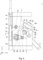
- Fig. 4 is a front view showing the manual unlocking device 1 relating to the first embodiment in the middle of operating.
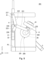
- Fig. 5 is a front view showing the manual unlocking device 1 relating to the first embodiment in an unlocking state.
- the manual unlocking device 1 includes an operating member 2, a converting mechanism 3, a drawing member 4, a slider mechanism 5, a gear mechanism 6 and a restriction wall 7.
- the manual unlocking device 1 further includes a case 8 housing therein part of the converting mechanism 3, drawing member 4, slider mechanism 5, gear mechanism 6 and restriction wall 7. In the respective drawings, part of the case 8 (for example, a cover) is not shown.
- the operating member 2 is configured to perform rotational motion between a locking position (shown in Fig. 3 ) and an unlocking position (shown in Fig. 5 ) as operated manually.
- the operating member 2 is rotatable 90 degrees on a support shaft 20 between the locking position and the unlocking position. In the locking position, the operating member 2 extends in the vertical direction. In the unlocking position, the operating member 2 extends in the horizontal direction.
- the operating member 2 has a portion coupled with the support shaft 20, and another portion that is opposite to the coupled portion. The latter portion is externally exposed or positioned outside the case 8 when the operating member 2 moves between the locking position and the unlocking position.
- the converting mechanism 3 converts the rotational motion of the operating member 2 into linear motion.
- the converting mechanism 3 has a plurality of links 21 and 22 configured to reach a dead center as a result of the rotational motion of the operating member 2 from the locking position to the unlocking position.
- the slider mechanism 5 is connected to the operating member 2 via the links 21 and 22.
- the slider mechanism 5 and converting mechanism 3 together constitute a slider crank mechanism.
- the links 21 and 22 include a first link 21 and a second link 22.
- the first link 21 is coupled at its one end to the operating member 2 such that it is rotatable on the coupling portion where the one end of the first link 21 is coupled with the operating member 2.
- the second link 22 is coupled at its one end to the other end of the first link 21 such that it is rotatable on the coupling portion where the one end of the second link 22 is coupled with the other end of the first link 21, and coupled at its other end to the slider mechanism 5 such that it is rotatable on the coupling portion where the other end of the second link 22 is coupled with the slider mechanism 5.
- the first link 21 is configured to rotate on a first shaft 25 that is parallel to the support shaft 20 and that is positioned in the coupling portion where the one end of the first link 21 is coupled with the operating member 2.
- the first link 21 extends in the vertical direction with the other end of the first link 21 being positioned above the one end when the operating member 2 is in the locking position.
- the first link 21 extends in the vertical direction with the other end of the first link 21 being positioned below the one end when the operating member 2 is in the unlocking position.
- the second link 22 is configured to rotate on a second shaft 26 that is parallel to the first shaft 25 and that is positioned in the coupling portion where the one end of the second link 22 is coupled with the other end of the first link 21.
- the second link 22 extends in the vertical direction with the other end of the second link 22 being positioned above the one end when the operating member 2 is in either the locking or unlocking position.
- the second link 22 originates at the one end and terminates at the other end, with the portion of the second link 22 including the one end extending toward the upper right in the drawing and the portion of the second link 22 including the other end extending toward the upper left in the drawing, when the operating member 2 is in either the locking or unlocking position.
- the second link 22 is V-shaped when seen in the direction in which the second shaft 26 extends. Specifically, the minimum angle of the V shape is obtuse.
- the drawing member 4 is a cable.
- the drawing member 4 is coupled at its one end to the converting mechanism 3.
- the drawing member 4 is coupled at its other end to the locking device 16.
- the drawing member 4 can transmit, to the locking device 16, the linear motion transmitted thereto from the converting mechanism 3, thereby unlocking the door device 15.
- the drawing member 4 is configured to move between a start point P1 and an end point P2 in synchronization with a slider 31 in the direction along the linear motion.
- the drawing member 4 may receive a pressing force (elastic force) acted upon by an elastic member such as a spring constituting the locking device 16. This means that the drawing member 4 is subject to a force that draws the drawing member 4 upwards in the vertical direction.
- the slider mechanism 5 supports the drawing member 4 (for example, an inner cable) such that the drawing member 4 is allowed to move in the direction along the linear motion.
- the other end of the drawing member 4 is secured onto the slider mechanism 5.
- the other end of the second link 22 is coupled with the slider mechanism 5.
- the slider mechanism 5 includes a slider 31 and a guide rail 32.
- the slider 31 has a protrusion 30 protruding toward the upper right in the drawing, and the guide rail 32 extends in the vertical direction.
- the slider 31 is supported on the guide rail 32 such that it can move along the guide rail 32.
- the slider mechanism 5 can be configured in any other manners as required by design specifications.
- the slider 31 may receive the pressing force (elastic force) acted upon by the elastic member such as a spring via the drawing member 4.
- the slider 31 is thus subject to a force that draws the slider 31 as well as the drawing member 4 upward in the vertical direction.
- the second link 22 is coupled at its other end to the tip of the protrusion 30 of the slider 31 such that it is rotatable on the coupling portion where the other end of the second link 22 is coupled with the tip of the protrusion 30.
- the second link 22 is configured to rotate on a third shaft 27 that is parallel to the second shaft 26 and that is positioned in the coupling portion where the other end of the second link 22 is coupled with the tip of the protrusion 30 of the slider 31.
- the gear mechanism 6 reduces the rotation of the support shaft 20 by a predetermined reduction ratio and transmits the reduced rotation to the one end of the first link 21.
- the gear mechanism 6 includes a driving gear 40 and a driven gear 50 that meshes with the driving gear 40 and that is driven to rotate.
- the driving gear 40 is rotatably coupled with the support shaft 20 with the center of rotation being placed on the support shaft 20.
- the driven gear 50 is coupled with the one end of the first link 21 with the center of rotation being placed on the one end of the first link 21.
- the driven gear 50 meshes with the driving gear 40 to transmit the rotational motion of the operating member 2 to the first link 21.
- a gear ratio B/A is defined as 1/2, where A and B respectively represent the numbers of teeth at the driving and driven gears 40 and 50.
- the gear ratio B/A is not limited to this value, and may be less than or greater than 1/2.
- the gear ratio B/A can be modified as required by design specifications.
- the driving gear 40 includes a gear portion 41 and a positioning portion 42.
- the gear portion 41 can mesh with the driven gear 50, and the positioning portion 42 is configured to place the driving gear 40 at an intended position when the operating member 2 is at the locking or unlocking position.
- the gear and positioning portions 41 and 42 are differently positioned on the circumference of an imaginary circle centered on the support shaft 20, on which the driving gear 40 can rotate.
- the gear portion 41 occupies a central angle of approximately 90 degrees of the imaginary circle centered on the support shaft 20, on which the driving gear 40 can rotate.
- the gear portion 41 can be arranged in any other manners.
- the gear portion 41 may occupy a central angle of less than or greater than 90 degrees of the imaginary circle centered on the support shaft 20, on which the driving gear 40 can rotate.
- the gear portion 41 can be arranged in any other manners as required by design specifications.
- the positioning portion 42 is positioned on the opposite side of the gear portion 41 in the radial direction of the circle centered on the support shaft 20, on which the driving gear 40 can rotate.
- the driving gear 40 includes a first depression 43 and a second depression 44.
- the first depression 43 can keep the driving gear 40 at an intended position while the operating member 2 is at the locking position
- the second depression 44 can keep the driving gear 40 at an intended position while the operating member 2 is at the unlocking position.
- the positioning portion 42 includes a wall portion having the first and second depressions 43 and 44 of the driving gear 40.
- a plunger 61 is provided on an inclined wall 60 of the case 8.
- the plunger 61 is a ball plunger, for example.
- the plunger 61 has a protrusion 62 (for example, a part of a ball) protruding toward the support shaft 20, on which the driving gear 40 can rotate.
- the protrusion 62 of the plunger 61 protrudes toward the lower left in the drawing from the inclined wall 60 of the case 8.
- the present embodiment is not limited to the above, and the protrusion 62 of the plunger 61 can protrude in any other manners as required by design specifications.
- the protrusion 62 of the plunger 61 is fitted in the first depression 43 of the driving gear 40. This enables the driving gear 40 to be at the intended position while the operating member 2 is at the locking position.
- the protrusion 62 of the plunger 61 is fitted in the second depression 44 of the driving gear 40. This enables the driving gear 40 to be at the intended position while the operating member 2 is at the unlocking position.
- the restriction wall 7 can restrict the rotational motion of the driving gear 40 by contacting the driving gear 40 before the drawing member 4 reaches the start point P1 or end point P2 .
- the restriction wall 7 is provided on the surface of the case 8 that faces the driving gear 40.
- the restriction wall 7 includes a first wall portion 71 and a second wall portion 72.
- the first wall portion 71 can restrict the rotational motion of the driving gear 40 by contacting the driving gear 40 before the drawing member 4 reaches the end point P2 as a result of moving in the direction along the linear motion from the start point P1 to the end point P2.
- the second wall portion 72 can restrict the rotational motion of the driving gear 40 by contacting the driving gear 40 before the drawing member 4 reaches the start point P1 as a result of moving in the direction along the linear motion from the end point P2 toward the start point P1.
- the second wall portion 72 can thus protect the gear portion 41 of the driving gear 40 by preventing a load from being applied to the gear portion 41 of the driving gear 40 even if the rotational motion of the operating member 2 results in the operating member 2 reaching beyond the locking position.
- the first wall portion 71 can thus protect the gear portion 41 of the driving gear 40 by preventing a load from being applied to the gear portion 41 of the driving gear 40 even if the rotational motion of the operating member 2 results in the operating member 2 reaching beyond the unlocking position.
- the first shaft 25 is positioned such that it does not overlap the route of the rotation of the second link 22, when seen in the direction in which the first shaft 25 extends.
- the first shaft 25 is positioned lower than the one end of the second link 22 in the vertical direction when the operating member 2 is in the locking position.
- the first shaft 25 is positioned higher than the one end of the second link 22 in the vertical direction when the operating member 2 is in the unlocking position.
- the first shaft 25 is positioned in the space between the opposite ends of the second link 22 when the operating member 2 is in the unlocking position.
- Fig. 3 is a front view showing the manual unlocking device 1 relating to the first embodiment in the locking state.
- Fig. 4 is a front view showing the manual unlocking device 1 relating to the first embodiment in the middle of operating.
- Fig. 5 is a front view showing the manual unlocking device 1 relating to the first embodiment in the unlocking state.
- the door leaves 11 are fully closed and locked by the locking device 16 in an ordinary circumstance, for example, while the vehicle is traveling.
- the door leaves 11 are locked while the vehicle is traveling, or if the door leaves 11 face away from a platform and cannot be used for passengers boarding or disembarking.
- the cable (drawing member 4) is drawn upward in the vertical direction by a pressing force (elastic force) exerted by a not-shown elastic member such as a spring.
- a pressing force elastic force
- a not-shown elastic member such as a spring.
- the slider 31 is also drawn upward in the vertical direction.
- the slider 31 is positioned near the start point P1 in the direction along the linear motion of the cable.
- the operating member 2 is rotated in the direction indicated by the arrow R in case of emergency or for maintenance purpose.
- the operating member 2 is rotated 90 degrees on the support shaft 20 between the locking position and the unlocking position.
- the driving gear 40 which is rotatably coupled with the support shaft 20 with the center of rotation being placed on the support shaft 20, is rotated in the direction indicated by the arrow R1.
- the driven gear 50 which meshes with the driving gear 40, is rotated in the direction indicated by the arrow R2 on the first shaft 25.
- An example case is assumed where the gear ratio B/A is 1/2. In this case, a 90 degree rotation of the operating member 2 on the support shaft 20 can result in a 180 degree rotation of the driven gear 50 on the first shaft 25.
- an imaginary line segment from the one end of the first link 21 to the other end of the first link 21, and an imaginary line segment from the one end of the second link 22 to the other end of the second link 22 are positioned on a straight line.
- the first and second links are at a dead center.
- the protrusion 62 of the plunger 61 is fitted in the second depression 44 of the driving gear 40, so that the driving gear 40 is placed at the intended position.
- the operating member 2 may move back to the original position (locking position) due to its own weight.
- the plunger 61 can stop this from happening.
- the manual unlocking device 1 relating to the first embodiment is configured to manually unlock the locking device 16 for locking the door device 15, which is configured to open or close the doorway 10 of the vehicle.
- the manual unlocking device 1 includes: the operating member 2 configured to perform rotational motion between the locking position and the unlocking position when manually operated; the converting mechanism 3 configured to convert the rotational motion of the operating member 2 into the linear motion; and the drawing member 4 coupled at one end thereof to the converting mechanism 3 and at the other end thereof to the locking device 16, the drawing member 4 being configured to transmit, to the locking device 16, the linear motion transmitted thereto from the converting mechanism 3, thereby unlocking the door device 15.
- the converting mechanism 3 has the links 21 and 22, which may reach a dead center as a result of the rotational motion of the operating member 2 from the locking position to the unlocking position.
- the operating member 2 is operated to perform rotational motion, so that the operating member 2 reaches the unlocking position. As a result, the door device 15 can be unlocked. On completion of this, the links 21 and 22 may be at a dead center. An external force may be applied from the locking device 16 to the drawing member 4 while the manual unlocking device 1 is in the unlocking state. According to the first embodiment, the operating member 2 can stay at the unlocking position without requiring electric power consumption.
- the manual unlocking device 1 relating to the first embodiment uses a cable as the drawing member 4.
- the manual unlocking device 1 further includes the slider mechanism 5 to which the cable is secured.
- the slider mechanism 5 supports the cable such that the cable is movable in the direction along the linear motion.
- the slider mechanism 5 is connected to the operating member 2 via the links 21 and 22. As configured in this way, the cable can be drawn via the slider mechanism 5. Unlocking can be thus performed in a stable manner.
- the links 21 and 22 include the first link 21 and second link 22.
- the first link 21 is coupled at its one end to the operating member 2 such that the first link is rotatable on the coupling portion where the one end of the first link 21 is coupled with the operating member 2.
- the second link 22 is coupled at its one end to the other end of the first link 21 such that the second link 22 is rotatable on the coupling portion where the one end of the second link 22 is coupled with the other end of the first link 21, and coupled at its other end to the slider mechanism 5 such that the second link 22 is rotatable on the coupling portion where the other end of the second link 22 is coupled with the slider mechanism 5.
- the imaginary line segment from the one end of the first link 21 to the other end of the first link 21, and the imaginary line segment from the one end of the second link 22 to the other end of the second link 22 are positioned on a straight line.
- the first and second links are at a dead center.
- the imaginary line segment from the one end of the first link 21 to the other end of the first link 21, and the imaginary line segment from the one end of the second link 22 to the other end of the second link 22 are positioned on a straight line.
- the first and second links 21 and 22 are at a dead center.
- An external force may be applied from the locking device 16 to the drawing member 4 while the operating member 2 is at the unlocking position.
- the operation member 2 can stay at the unlocking position without requiring electric power consumption.
- the operating member 2 is rotatable 90 degrees on the support shaft 20 between the locking position and the unlocking position.
- the manual unlocking device 1 further includes the gear mechanism 6 configured to reduce the rotation of the support shaft 20 by a predetermined reduction ratio and transmit the reduced rotation to the one end of the first link 21. According to the above, since the amount of rotational motion of the operating member 2 can be amplified, the cable can be drawn by a certain amount with a shorter first link 21.
- the gear mechanism 6 includes: the driving gear 40 rotatably coupled with the support shaft 20 with the center of rotation being placed on the support shaft 20; and the driven gear 50 coupled with the one end of the first link 21 with the center of rotation being placed on the one end of the first link 21, the driven gear 50 meshing with the driving gear 40 to transmit the rotational motion of the operating member 2 to the first link 21.
- the driving gear 40 includes: the gear portion 41 meshing with the driven gear 50; and the positioning portion 42 configured to place the driving gear 40 at an intended position when the operating member 2 is at the locking or unlocking position.
- the gear portion 41 and positioning portion 42 are differently positioned on the circumference of an imaginary circle centered on the support shaft 20, on which the driving gear 40 can rotate. According to the above, the gear portion 41 and positioning portion 42 are arranged on the circumference of the same imaginary circle. For this reason, the positioning portion 42 can assist the operating member 2 in working stably, and the driving gear 40 does not require an increased size.
- the drawing member 4 specifically, the cable is configured to move between the start point P1 and the end point P2 in the direction along the linear motion.
- the manual unlocking device 1 further includes the restriction wall 7 for restricting the rotational motion of the driving gear 40 by contacting the driving gear 40 before the cable reaches the start point P1 or end point P2 as a result of moving in the direction along the linear motion.
- the restriction wall 7 can protect the gear portion 41 of the driving gear 40 by preventing a load from being applied to the gear portion 41 of the driving gear 40 even if excessive rotational motion of the operating member 2 results in the operating member 2 reaching beyond the locking or unlocking position.
- the first link 21 is configured to rotate on the first shaft 25 that is parallel to the support shaft 20 and that is positioned in the coupling portion where the one end of the first link 21 is coupled with the operating member 2.
- the first shaft 25 is positioned such that it does not overlap the route of the rotation of the second link 22 when seen in the direction in which the first shaft 25 extends. In this manner, the manual unlocking device 1 can avoid an increase in size in the direction in which the first shaft 25 extends, when compared with a case where the first shaft 25 is arranged such that it overlaps the route of the rotation of the second link 22 when seen in the direction in which the first shaft 25 extends.
- the drawing member is a cable, but the present embodiment is not limited to such.
- the drawing member may be any member other than a cable.
- the drawing member 10 may include chains, rods and hooks.
- the drawing member can be configured in any other manners as required by design specifications.
- the manual unlocking device further includes the slider mechanism to which the cable is secured, where the slider mechanism supports the cable such that the cable is movable in the direction along the linear motion.
- the present embodiment is not limited to such.
- the manual unlocking device may be embodied without the slider mechanism.
- the manual unlocking device may be configured such that the cable may be drawn without the slider mechanism.
- the slider mechanism can be installed in any other manners as required by design specifications.
- the other end of the second link is coupled with the slider mechanism, but the present embodiment is not limited to such.
- the other end of the second link may not be coupled with the slider mechanism.
- the other end of the second link may be coupled with the cable without the slider mechanism.
- the other end of the second link can be coupled in any other manners as required by design specifications.
- the operating member is rotatable 90 degrees on the support shaft between the locking position and the unlocking position, but the present embodiment is not limited to such.
- the operating member may be rotatable less than or greater than 90 degrees on the support shaft between the locking position and the unlocking position.
- the operating member can be configured to rotate any other degrees on the support shaft between the locking position and the unlocking position as required by design specifications.
- the manual unlocking device further includes the gear mechanism configured to reduce the rotation of the support shaft by a predetermined reduction ratio and transmit the reduced rotation to the one end of the first link, but the present embodiment is not limited to such.
- the manual unlocking device may be embodied without the gear mechanism.
- the manual unlocking device may include a belt pulley mechanism, a mechanism including a chain, or the like in place of the gear mechanism.
- the one end of the first link may be coupled with the operating member such that the firs link is rotatable on the coupling portion where the one end of the first link is coupled with the operating member.
- the gear mechanism can be installed in any other manners as required by design specifications.
- the gear mechanism includes: the driving gear rotatably coupled with the support shaft with the center of rotation being placed on the support shaft; and the driven gear coupled with the one end of the first link with the center of rotation being placed on the one end of the first link, the driven gear meshing with the driving gear to transmit the rotational motion of the operating member to the first link.
- the driving gear includes: the gear portion meshing with the driven gear; and the positioning portion configured to position the driving gear at an intended position when the operating member is at the locked or unlocking position.
- the driving gear may be embodied with the gear portion but without the positioning portion.
- the driving gear can be configured in any other manners as required by design specifications.
- the gear portion and positioning portion are differently positioned on the circumference of an imaginary circle centered on the support shaft, on which the driving gear can rotate.
- the present embodiment is not limited to such.
- the gear portion and positioning portion may not be differently positioned on the circumference of an imaginary circle centered on the support shaft, on which the driving gear can rotate.
- the gear portion and positioning portion may be positioned on the circumferences of imaginary circles having different diameters that are both centered on the support shaft, on which the driving gear can rotate.
- the gear portion and positioning portion can be arranged in any other manners as required by design specifications.
- the drawing member or cable is configured to move between the start point and the end point in the direction along the linear motion
- the manual unlocking device further includes the restriction wall for restricting the rotational motion of the driving gear by contacting the driving gear before the cable reaches the start or end point as a result of moving in the direction along the linear motion.
- the manual unlocking device may be embodied without the restriction wall.
- the restriction wall can be installed in any other manners as required by design specifications.
- the first link is rotatable on the first shaft that is parallel to the support shaft and that is positioned in the coupling portion where the one end of the first link is coupled with the operating member.
- the first shaft is positioned such that it does not overlap the route of the rotation of the second link when seen in the direction in which the first shaft extends.
- the present embodiment is not limited to such.
- the first shaft may be positioned such that it overlaps the route of the rotation of the second link, when seen in the direction in which the first shaft extends.
- the first shaft can be installed in any other manners as required by design specifications.
- Fig. 6 is a perspective view showing the manual unlocking device 201 relating to the second embodiment in a locking state.
- Fig. 7 is a front view showing the manual unlocking device 201 relating to the second embodiment in the locking state.
- Fig. 8 is a front view showing the manual unlocking device 201 relating to the second embodiment in the middle of operating.
- Fig. 9 is a front view showing the manual unlocking device 201 relating to the second embodiment in an unlocking state.
- the manual unlocking device 201 includes an operating member 2, a converting mechanism 203, a drawing member 4, a slider mechanism 5, a transmission member 209 and a case 8. In the respective drawings, part of the case 8 (for example, a cover) is not shown.
- the operating member 2 is configured to rotate between a locking position (shown in Fig. 7 ) and an unlocking position (shown in Fig. 9 ) as operated manually.
- the operating member 2 is rotatable 90 degrees on a support shaft 20 between the locking position and the unlocking position. In the locking position, the operating member 2 extends in the vertical direction. In the unlocking position, the operating member 2 extends in the horizontal direction.
- the converting mechanism 203 converts the rotational motion of the operating member 2 into linear motion.
- the converting mechanism 203 has a plurality of links 221, 222, 223 that are configured to reach a dead center as a result of the rotational motion of the operating member 2 from the locking position to the unlocking position.
- the slider mechanism 5 is connected to the operating member 2 via the links 221, 222, 223.
- the slider mechanism 5 and conversion mechanism 203 together constitute a slider crank mechanism.
- the links 221, 222 and 223 include a first link 221, a second link 222 and a third link 223.
- the first link 221 is coupled at its one end to the operating member 2 such that it is rotatable on the coupling portion where the one end of the first link 221 is coupled with the operating member 2.
- the second link 222 is coupled at its one end to the other end of the first link 221 such that the second link 222 is rotatable on the coupling portion where the one end of the second link 222 is coupled with the other end of the first link 221, and coupled at its other end to the case 8 (an example of a stationary site) such that the second link 222 is rotatable on the coupling portion where the other end of the second link 222 is coupled with the case 8.
- the third link 223 is coupled at its one end to the one end of the second link 222 such that the third link 223 is rotatable on the coupling portion where the one end of the third link 223 is coupled with the one end of the second link 222, and coupled at its other end to the slider mechanism 5 such that the third link 223 is rotatable on the coupling portion where the other end of the third link 223 is coupled with the slider mechanism 5.
- the first link 221 is configured to rotate on a first shaft 225 that is parallel to the support shaft 20 and that is positioned in the coupling portion where the one end of the first link 221 is coupled with the operating member 2.
- the first link 221 extends toward the upper left with the other end of the first link 221 being positioned above the one end when the operating member 2 is in the locking position (see Fig. 7 ).
- the first link 221 extends toward the upper left with the other end of the first link 221 being positioned above the one end at a smaller gradient than in the case shown in Fig. 7 when the operating member 2 is in the unlocking position (see Fig. 9 ).
- the first link 221 has one end supporting part of the transmission member 209 on either side in the X direction, and the other end supporting one end of the second link 222 and one end of the third link 223 on either side in the X direction.
- the first link 221 is configured to support target components on either side.
- the present embodiment is not limited to this, and the first link 221 may be configured to support target components on one side.
- the first link 221 can be configured in any other manners as required by design specifications.
- the length of the second link 222 from the one end to the other end is less than the length of the first link 221 from the one end to the other end.
- the second link 222 is configured to rotate on a second shaft 226 that is parallel to the first shaft 225 and that is positioned in the coupling portion where the one end of the second link 222 is coupled with the other end of the first link 221.
- the second link 222 is configured to rotate on a third shaft 227 that is parallel to the second shaft 226 and that is positioned in the coupling portion where the other end of the second link 222 is coupled with the case 8.
- the second link 222 extends toward the upper left with the other end of the second link 222 being positioned above the one end at a greater gradient than the first link 221 when the operating member 2 is at the locking position (see Fig. 7 ).
- the second link 222 extends in the vertical direction with the other end of the second link 222 being positioned above the one end when the operating member 2 is at the unlocking position.
- the length of the third link 223 from the one end to the other end is less than the length of the second link 222 from the one end to the other end.
- the third link 223 is configured to rotate on the second shaft 226 that is positioned in the coupling portion where the one end of the third link 223 is coupled with the one end of the second link 222.
- the third link 223 is coupled such that it is rotatable on a fourth shaft 228 that is parallel to the third shaft 227 and that is positioned in the coupling portion where the other end of the third link 223 is coupled with the slide mechanism 5.
- the third link 223 extends toward the lower left with the other end of the third link 223 being positioned below the one end (at a gradient close to zero) when the operating member 2 is at the locking position (see Fig. 7 ).
- the third link 223 extends in the vertical direction with the other end of the third link 223 being positioned below the one end when the operating member 2 is at the unlocking position (see Fig. 9 ).
- the drawing member 4 is coupled at one end to the converting mechanism 203.
- the drawing member 4 is coupled at the other end to the locking device 16.
- the drawing member 4 can transmit, to the locking device 16, the linear motion transmitted thereto from the converting mechanism 203, thereby unlocking the door device 15.
- the drawing member 4 is configured to move between a start point P1 and an end point P2 in synchronization with a slider 31 in the direction along the linear motion.
- the slider mechanism 5 supports the drawing member 4 (for example, an inner cable) such that the drawing member 4 is allowed to move in the direction along the linear motion.
- the other end of the drawing member 4 is secured onto the slider mechanism 5.
- the third link 223 is coupled with the slider mechanism 5 such that it is rotatable on the coupling portion where the other end of the third link 223 is coupled with the slider mechanism 5.
- the slider mechanism 5 includes the slider 31 and a guide rail 32.
- the slider 31 has the fourth shaft 228, and the guide rail 32 extends in the vertical direction.
- the slider 31 is supported on the guide rail 32 such that it can move along the guide rail 32.
- the present embodiment is not limited to the above, and the slider mechanism 5 can be configured in any other manners as required by the design specifications.
- the slider 31 may receive a pressing force (elastic force) acted upon by an elastic member such as a spring via the drawing member 4.
- the slider 31 is thus subject to a force that draws the slider 31 as well as the drawing member 4 upward in the vertical direction.
- the transmission member 209 transmits the rotation of the shaft 20 to the one end of the first link 221.
- the transmission member 209 includes a first transmission portion 291, a second transmission portion 292, and a positioning portion 42.
- the first transmission portion 291 has the support shaft 20.
- the second transmission portion 292 has the first shaft 225.
- the positioning portion 42 is configured to place the transmission member 209 at an intended position when the operating member 2 is at the locking or unlocking position.
- the first transmission portion 291 is coupled with the operating member 2 via the support shaft 20 with the center of rotation being placed on the support shaft 20.
- the second transmission portion 292 is coupled with the first transmission portion 291 such that they constitute a single piece, and transmits the rotational motion of the operating member 2 to the first link 221.
- the second transmission portion 292 has one end overlapping the support shaft 20 when seen in the direction in which the first shaft 225 extends.
- the second transmission portion 292 has the other end where the first shaft 225 is provided.
- the second transmission portion 292 extends such that the other end of the second transmission portion 292 is positioned on the right side of the one end when the operating member 2 is at the locking position (see Fig. 7 ).
- the second transmission portion 292 extends in the vertical direction with the other end of the second transmission portion 292 being positioned above the one end when the operating member 2 is at the unlocking position (see Fig. 9 ).
- the positioning portion 42 is provided on the outer periphery of the first transmission portion 291 of the transmission member 209.
- the first transmission portion 291 has a first depression 43 and a second depression 44.
- the first depression 43 can keep the transmission member 209 at the intended position while the operating member 2 is at the locking position
- the second depression 44 can keep the transmission member 209 at the intended position while the operating member 2 is at the unlocking position.
- the positioning portion 42 includes a wall portion having the first and second depressions 43 and 44 of the transmission member 209.
- the protrusion 62 of the plunger 61 is fitted in the first depression 43 of the transmission member 209 (see Fig. 7 ). This enables the transmission member 209 to be at the intended position while the operating member 2 is at the locking position.
- the protrusion 62 of the plunger 61 is fitted in the second depression 44 of the transmission member 209 (see Fig. 9 ). This enables the transmission member 209 to be at the intended position while the operating member 2 is at the unlocking position.
- the door leaves 11 are fully closed and locked by the locking device 16 in an ordinary circumstance, for example, while the vehicle is traveling (see Fig. 1 ).
- the door leaves 11 are locked while the vehicle is traveling, or if the door leaves 11 face away from a platform and cannot be used for passengers boarding or disembarking.
- the cable (drawing member 4) is drawn upward in the vertical direction by a pressing force (elastic force) exerted by a not-shown elastic member such as a spring.
- a pressing force elastic force
- a not-shown elastic member such as a spring.
- the slider 31 is drawn upward in the vertical direction.
- the slider 31 is positioned near the start point P1 in the direction along the linear motion of the cable.
- the operating member 2 is rotated in the direction indicated by the arrow R.
- the operating member 2 is rotated 90 degrees on the support shaft 20 between the locking position and the unlocking position.
- the transmission member 209 which is coupled with the support shaft 20, is rotated in the direction indicated by the arrow R1.
- the rotational motion of the operating member 2 is transmitted to the first link 221.
- the second and third links 222 and 223 then rotationally move as shown in Figs. 7 , 8 and 9 .
- the one end of the second link 222 and the one end of the third link 223 are located below the third shaft 227 in the vertical direction in Fig. 9 .
- the second, third and fourth shafts 226, 227 and 228 are aligned with each other on the same vertical line.
- an imaginary line segment from the one end of the second link 222 to the other end of the second link 222, and an imaginary line segment from the one end of the third link 223 to the other end of the third link 223 are positioned on a straight line.
- the second and third links 222 and 223 are at a dead center.
- the protrusion 62 of the plunger 61 is fitted in the second depression 44 of the transmission member 209, so that the transmission member 209 is placed at the intended position.
- the operating member 2 may move back to the original position (locking position) due to its own weight.
- the plunger 61 can stop this from happening.
- Fig. 10 shows the linkage of the manual unlocking device 201 relating to the second embodiment.
- the second link 222, third link 223 and slider 31 constitute the linkage.
- the third shaft 227 is the fixed pivot
- the fourth shaft 228 moves in the vertical direction
- the symbols "F1" and "F2" respectively indicate the force applied to the second shaft 226 and the force drawing the cable
- the slider moves in the Z direction.
- the distance between the central point of the second shaft 226 and the central point of the fourth shaft 228 is less than the distance between the central point of the second shaft 226 and the central point of the third shaft 227.
- the angle (acute angle) formed by the central point of the third shaft 227, the central point of the second shaft 226 and the central point of the fourth shaft 228 is divided by a perpendicular line to the direction of the motion of the slider (Z direction) into an angle A1 and an angle A2.
- Formula 1 indicates that the force F1 required to produce the cable drawing force F2 may decline.
- the cable drawing force F2 reaches the maximum value, but the force F1 (equivalent to the force required to operate the operating member 2) is reduced. Therefore, the operating member 2 achieves improved operability.
- the manual unlocking device 201 relating to the second embodiment includes the first, second and third links 221, 222 and 223.
- the first link 221 is coupled at its one end to the operating member 2 such that it is rotatable on the coupling portion where the one end of the first link 221 is coupled with the operating member 2.
- the second link 222 is coupled at the one end to the other end of the first link 221 such that it is rotatable on the coupling portion where the one end of the second link 222 is coupled with the other end of the first link 221, and coupled at the other end to the case 8 such that it is rotatable on the coupling portion where the other end of the second link 222 is coupled the case 8.
- the third link 223 is coupled at its one end to the one end of the second link 222 such that it is rotatable on the coupling portion where the one end of the third link 223 is coupled with the one end of the second link 222, and coupled at its other end to the slider mechanism 5 such that it is rotatable on the coupling portion where the other end of the third link 223 is coupled with the slider mechanism 5.
- the imaginary line segment from the one end of the second link 222 to the other end of the second link 222, and the imaginary line segment from the one end of the third link 223 to the other end of the third link 223 are positioned on a straight line. In other words, the second and third links 222 and 223 are at a dead center.
- the imaginary line segment from the one end of the second link 222 to the other end of the second link 222 and the imaginary line segment from the one end of the third link 223 to the other end of the third link 223 are on a straight line.
- An external force may be applied by the locking device 16 to the drawing member 4 while the operating member 2 is at the unlocking position. Even so, the operating member 2 can stay at the unlocking position without requiring electric power consumption.
- the operating member 2 is rotatable on the support shaft 20 between the locking position and the unlocking position.
- the manual unlocking device 1 further includes the transmission member 209 configured to transmit the rotation of the support shaft 20 to the one end of the first link 221. As configured in this manner, the manual unlocking device 201 needs no gear mechanism (gear portion) for transmitting the rotation. This can result in improved strength and rigidity.
- the length of the third link 223 from the one end to the other end is less than the length of the second link 222 from the one end to the other end.
- the third link 223 can thus follow the rotation of the first link 221 in a better manner than in the case where the length of the third link 223 from the one end to the other end is greater than the length of the second link 222 from the one end to the other end.
- the operating member 2 can thus achieve improved operability.
- the second link 222, third link 223 and slider 31 constitute a linkage satisfying Formula 1 mentioned above. Since the links 222 and 223 are at a dead center when the operating member 2 is at the unlocking position, the retaining force can be advantageously increased. At the same time, as the operating member 2 approaches the unlocking position, the load may increase, but the force for drawing the cable can be exerted with reduced force for operating the operating member 2.
- the vehicle door includes the pair of door leaves separately slidable to open or close the doorway of the railway vehicle.
- the embodiments are not limited to such.
- the vehicle door may be provided on vehicles other than railway vehicles.
- the vehicle door may include a single leaf sliding door.
- the second link is coupled at the other end to the case such that the second link is rotatable on the coupling portion where the other end of the second link is coupled with the case, but the embodiment is not limited to such.
- the second link may be coupled at the other end to a stationary site other than the case, for example, a vehicle body, such that the second link is rotatable on the coupling portion where the other end of the second link is coupled with the stationary site.
- the other end of the second link can be coupled in any other manners (to any other stationary sites) as required by design specifications.
- the elements of the embodiments described above may be replaced with known elements within the purport of the present invention. Further, the variations described above may be combined.
- the foregoing embodiments disclosed herein describe a plurality of physically separate constituent parts. They may be combined into a single part, and any one of them may be divided into a plurality of physically separate constituent parts. Irrespective of whether or not the constituent parts are integrated, they are acceptable as long as they are configured to attain the object of the invention.
- a plurality of functions are distributively provided. Some or all of the functions may be integrated. Conversely, a plurality of functions may be integrated. Some or all of the functions can be distributively provided. Irrespective of whether or not the functions are integrated or distributed, they are acceptable as long as they are configured to attain the object of the invention.
Landscapes
- Lock And Its Accessories (AREA)
Abstract
Description
- The present invention relates to a manual unlocking device.
-
Patent Literature 1 discloses a technique of manually unlocking a latch lock locking a door by operating a handle device connected to a cable. - Patent Literature 1:
Japanese Patent Application Publication No. 2010-174435 - The handle device has an operating unit that is generally connected directly to the inner cable. While the handle device is in an unlocking state, an external force may be applied in a locking direction to the cable from the latch lock. In this case, the external force directly pulls the operating unit. To address this issue, a ball plunger or the like may be provided to place the operating unit at a fixed position, so that the operating unit can remain at an unlocking position. In this manner, such an external force does not accidentally bring the operating unit back to a locking position. As long as the ball plunger exerts strong retaining force, the operating unit can be prevented from returning to the locking position when acted upon by an external force. To operate the operating unit, however, a great deal of efforts are required.
- The present invention is intended to overcome the above problem, and one object thereof is to provide a manual unlocking device that is capable of retaining an operating member in an unlocking position without requiring electric power even if an external force is applied to a drawing member from a locking device while the manual unlocking device is in an unlocking state.
- To overcome the above drawback, aspects of the present invention are configured as follows.
- (1) An aspect of the present invention provides a manual unlocking device for manually unlocking a locking device, the locking device being configured to lock a door device, the door device being configured to open or close a doorway of a vehicle, the manual unlocking device including: an operating member configured to perform rotational motion between a locking position and an unlocking position by being manually operated; a converting mechanism configured to convert the rotational motion of the operating member into linear motion; and a drawing member coupled at one end thereof to the converting mechanism and at the other end thereof to the locking device, the drawing member being configured to transmit, to the locking device, the linear motion transmitted thereto from the converting mechanism, thereby unlocking the door device. The converting mechanism has a plurality of links configured to reach a dead center as a result of the rotational motion of the operating member from the locking position to the unlocking position.
According to the above, the operating member is operated to perform rotational motion, so that the operating member reaches the unlocking position. As a result, the door device can be unlocked. On completion of this, the links may be at a dead center. An external force may be applied by the locking device to the drawing member while the operating member is at the unlocking position. Even so, the operating member can stay at the unlocking position without requiring electric power consumption. - (2) In the manual unlocking device of (1), the drawing member may be a cable, the manual unlocking device may further include a slider mechanism to which the cable is secured, the slider mechanism supporting the cable such that the cable is movable in a direction along the linear motion, and the slider mechanism is connected to the operating member via the links.
- (3) In the manual unlocking device of (2), the links may include: a first link coupled at one end thereof to the operating member such that the first link is rotatable on a coupling portion where the one end of the first link is coupled with the operating member; and a second link coupled at one end thereof to the other end of the first link such that the second link is rotatable on a coupling portion where the one end of the second link is coupled with the other end of the first link, and coupled at the other end thereof to the slider mechanism such that the second link is rotatable on a coupling portion where the other end of the second link is coupled with the slider mechanism. As a result of the rotational motion of the operating member from the locking position to the unlocking position, an imaginary line segment from the one end of the first link to the other end of the first link, and an imaginary line segment from the one end of the second link to the other end of the second link are positioned on a straight line, so that the first and second links are at a dead center.
- (4) In the manual unlocking device of (3), the operating member may be rotatable 90 degrees on a support shaft between the locking position and the unlocking position, and the manual unlocking device may further include a gear mechanism configured to reduce rotation of the support shaft by a predetermined reduction ratio and transmit the reduced rotation to the one end of the first link.
- (5) In the manual unlocking device of (4), the gear mechanism may include: a driving gear rotatably coupled with the support shaft with a center of rotation thereof being placed on the support shaft; and a driven gear having coupled with the one end of the first link with a center of rotation thereof being placed on the one end of the first link, the driven gear meshing with the driving gear to transmit the rotational motion of the operating member to the first link, the driving gear may have: a gear portion meshing with the driven gear; and a positioning portion being configured to place the driving gear at an intended position when the operating member is at the locking or unlocking position, and the gear portion and the positioning portion may be differently positioned on a circumference of an imaginary circle centered on the support shaft on which the driving gear is rotatable.
- (6) In the manual unlocking device of (5), the drawing member may be the cable configured to move between a start point and an end point in a direction along the linear motion, and the manual unlocking device may further include a restriction wall configured to restrict rotational motion of the driving gear by contacting the driving gear before the cable reaches the start point or end point as a result of moving in the direction along the linear motion.
- (7) In the manual unlocking device of any one of (4) to (6), the first link may be configured to rotate on a first shaft that is parallel to the support shaft and that is positioned in the coupling portion where the one end of the first link is coupled with the operating member, and the first shaft may be positioned such that the first shaft does not overlap a route of rotation of the second link, when seen in a direction in which the first shaft extends.
- (8) In the manual unlocking device of (2), the links may include: a first link coupled at one end thereof to the operating member such that the first link is rotatable on a coupling portion where the one end of the first link is coupled with the operating member; a second link coupled at one end thereof to the other end of the first link such that the second link is rotatable on a coupling portion where the one end of the second link is coupled with the other end of the first link, and coupled at the other end thereof to a stationary site such that the second link is rotatable on a coupling portion where the other end of the second link is coupled with the stationary site; and a third link coupled at one end thereof to the one end of the second link such that the third link is rotatable on a coupling portion where the one end of the third link is coupled with the one end of the second link, and coupled at the other end thereof to the slider mechanism such that the third link is rotatable on a coupling portion where the other end of the third link is coupled with the slider mechanism. As a result of the rotational motion of the operating member from the locking position to the unlocking position, an imaginary line segment from the one end of the second link to the other end of the second link and an imaginary line segment from the one end of the third link to the other end of the third link may be positioned on a straight line, so that the second and third links are at a dead center.
- (9) In the manual unlocking device of (8), the operating member may be rotatable on a support shaft between the locking position and the unlocking position, and the manual unlocking device may further include a transmission member configured to transmit rotation of the support shaft to the one end of the first link.
- (10) In the manual unlocking device of (8) or (9), a length of the third link from the one end to the other end may be less than a length of the second link from the one end to the other end.
- According to the present invention, the operating member can remain in the unlocking position without requiring electric power even if an external force is applied to the drawing member from the locking device while the manual unlocking device is in an unlocking state.
-
-
Fig. 1 shows a vehicle door relating to a first embodiment viewed from outside in a width direction. -
Fig. 2 is a perspective view showing a manual unlocking device relating to the first embodiment in a locking state. -
Fig. 3 is a front view showing the manual unlocking device relating to the first embodiment in the locking state. -
Fig. 4 is a front view showing the manual unlocking device relating to the first embodiment in the middle of operating. -
Fig. 5 is a front view showing the manual unlocking device relating to the first embodiment in an unlocking state. -
Fig. 6 is a perspective view showing a manual unlocking device relating to a second embodiment in a locking state. -
Fig. 7 is a front view showing the manual unlocking device relating to the second embodiment in the locking state. -
Fig. 8 is a front view showing the manual unlocking device relating to the second embodiment in the middle of operating. -
Fig. 9 is a front view showing the manual unlocking device relating to the second embodiment in an unlocking state. -
Fig. 10 illustrates a linkage of the manual unlocking device relating to the second embodiment. - Embodiments of the present invention will now be described with reference to the attached drawings. The following embodiments are described with reference to an example manual unlocking device configured to manually unlock a locking device for locking a door device for opening or closing a doorway of a railway vehicle (vehicle). In the following description, terms such as "parallel," "orthogonal," "center" and "coaxial" describe relative or absolute positions. These terms are not only strictly used but also allow some tolerances and relative differences in angle and distance as long as the same effects can be still produced. In the drawings used for the following description, members are shown to different scales into recognizable sizes.
-
Fig. 1 shows a vehicle door relating to a first embodiment from outside in a width direction. As shown inFig. 1 , the vehicle door is a double sliding door including a pair ofdoor leaves 11 to open or close adoorway 10 of a vehicle.Fig. 1 shows a state where thedoor leaves 11 are fully closed. - In the following description, an XYZ orthogonal coordinate system is used as required. The X direction represents the front-rear direction of the vehicle. The Y direction represents the width direction of the vehicle. The Z direction represents the height direction of the vehicle (the gravitational direction), which is orthogonal to the X and Y directions. The following description is made with the arrows shown in the drawings indicating the X, Y and Z directions, and the head side and the tail side of each arrow indicate the positive (+) side and the negative (-) side, respectively. The outside and the inside in the width direction are respectively denoted as the +Y side and the -Y side. The upper side and the lower side in the gravitational direction are respectively denoted as the +Z side and the -Z side.
- The
door leaves 11 may move in the X direction to open or close thedoorway 10 when acted upon by a driving force from a driving source (for example, motor), which is not shown. Above thedoorway 10, a door device 15 for opening or closing thedoorway 10 of the vehicle, and a locking device 16 for locking the door device 15 are provided. - A manual unlocking
device 1 is configured to manually unlock the locking device 16 for locking the door device 15, which is configured to open or lose thedoorway 10 of the vehicle. The manual unlockingdevice 1 is connected to the locking device 16 via a drawingmember 4. For example, the manual unlockingdevice 1 may be arranged such that it can be operated inside or outside the vehicle. For example, the manual unlockingdevice 1 may be positioned such that it can be operated by a passenger, a crew member, a station staff member in case of emergency. For example, the manual unlockingdevice 1 can be arranged in any other manners as required by design specifications. -
Fig. 2 is a perspective view showing the manual unlockingdevice 1 relating to the first embodiment in a locking state.Fig. 3 is a front view showing the manual unlockingdevice 1 relating to the first embodiment in the locking state.Fig. 4 is a front view showing the manual unlockingdevice 1 relating to the first embodiment in the middle of operating.Fig. 5 is a front view showing the manual unlockingdevice 1 relating to the first embodiment in an unlocking state. Referring toFigs. 2 to 5 , the manual unlockingdevice 1 includes an operatingmember 2, a convertingmechanism 3, a drawingmember 4, aslider mechanism 5, agear mechanism 6 and arestriction wall 7. The manual unlockingdevice 1 further includes acase 8 housing therein part of the convertingmechanism 3, drawingmember 4,slider mechanism 5,gear mechanism 6 andrestriction wall 7. In the respective drawings, part of the case 8 (for example, a cover) is not shown. - The operating
member 2 is configured to perform rotational motion between a locking position (shown inFig. 3 ) and an unlocking position (shown inFig. 5 ) as operated manually. The operatingmember 2 is rotatable 90 degrees on asupport shaft 20 between the locking position and the unlocking position. In the locking position, the operatingmember 2 extends in the vertical direction. In the unlocking position, the operatingmember 2 extends in the horizontal direction. The operatingmember 2 has a portion coupled with thesupport shaft 20, and another portion that is opposite to the coupled portion. The latter portion is externally exposed or positioned outside thecase 8 when the operatingmember 2 moves between the locking position and the unlocking position. - The converting
mechanism 3 converts the rotational motion of the operatingmember 2 into linear motion. The convertingmechanism 3 has a plurality oflinks member 2 from the locking position to the unlocking position. Theslider mechanism 5 is connected to the operatingmember 2 via thelinks slider mechanism 5 and convertingmechanism 3 together constitute a slider crank mechanism. Thelinks first link 21 and asecond link 22. Thefirst link 21 is coupled at its one end to the operatingmember 2 such that it is rotatable on the coupling portion where the one end of thefirst link 21 is coupled with the operatingmember 2. Thesecond link 22 is coupled at its one end to the other end of thefirst link 21 such that it is rotatable on the coupling portion where the one end of thesecond link 22 is coupled with the other end of thefirst link 21, and coupled at its other end to theslider mechanism 5 such that it is rotatable on the coupling portion where the other end of thesecond link 22 is coupled with theslider mechanism 5. - The
first link 21 is configured to rotate on afirst shaft 25 that is parallel to thesupport shaft 20 and that is positioned in the coupling portion where the one end of thefirst link 21 is coupled with the operatingmember 2. Thefirst link 21 extends in the vertical direction with the other end of thefirst link 21 being positioned above the one end when the operatingmember 2 is in the locking position. Thefirst link 21 extends in the vertical direction with the other end of thefirst link 21 being positioned below the one end when the operatingmember 2 is in the unlocking position. - The
second link 22 is configured to rotate on asecond shaft 26 that is parallel to thefirst shaft 25 and that is positioned in the coupling portion where the one end of thesecond link 22 is coupled with the other end of thefirst link 21. Thesecond link 22 extends in the vertical direction with the other end of thesecond link 22 being positioned above the one end when the operatingmember 2 is in either the locking or unlocking position. Specifically, thesecond link 22 originates at the one end and terminates at the other end, with the portion of thesecond link 22 including the one end extending toward the upper right in the drawing and the portion of thesecond link 22 including the other end extending toward the upper left in the drawing, when the operatingmember 2 is in either the locking or unlocking position. Thesecond link 22 is V-shaped when seen in the direction in which thesecond shaft 26 extends. Specifically, the minimum angle of the V shape is obtuse. - For example, the drawing
member 4 is a cable. The drawingmember 4 is coupled at its one end to the convertingmechanism 3. The drawingmember 4 is coupled at its other end to the locking device 16. The drawingmember 4 can transmit, to the locking device 16, the linear motion transmitted thereto from the convertingmechanism 3, thereby unlocking the door device 15. The drawingmember 4 is configured to move between a start point P1 and an end point P2 in synchronization with aslider 31 in the direction along the linear motion. - Although not shown, the drawing
member 4 may receive a pressing force (elastic force) acted upon by an elastic member such as a spring constituting the locking device 16. This means that the drawingmember 4 is subject to a force that draws the drawingmember 4 upwards in the vertical direction. - The
slider mechanism 5 supports the drawing member 4 (for example, an inner cable) such that the drawingmember 4 is allowed to move in the direction along the linear motion. The other end of the drawingmember 4 is secured onto theslider mechanism 5. The other end of thesecond link 22 is coupled with theslider mechanism 5. - According to the shown example, the
slider mechanism 5 includes aslider 31 and aguide rail 32. Theslider 31 has aprotrusion 30 protruding toward the upper right in the drawing, and theguide rail 32 extends in the vertical direction. Theslider 31 is supported on theguide rail 32 such that it can move along theguide rail 32. Theslider mechanism 5 can be configured in any other manners as required by design specifications. - The
slider 31 may receive the pressing force (elastic force) acted upon by the elastic member such as a spring via the drawingmember 4. Theslider 31 is thus subject to a force that draws theslider 31 as well as the drawingmember 4 upward in the vertical direction. - The
second link 22 is coupled at its other end to the tip of theprotrusion 30 of theslider 31 such that it is rotatable on the coupling portion where the other end of thesecond link 22 is coupled with the tip of theprotrusion 30. Thesecond link 22 is configured to rotate on athird shaft 27 that is parallel to thesecond shaft 26 and that is positioned in the coupling portion where the other end of thesecond link 22 is coupled with the tip of theprotrusion 30 of theslider 31. - The
gear mechanism 6 reduces the rotation of thesupport shaft 20 by a predetermined reduction ratio and transmits the reduced rotation to the one end of thefirst link 21. Thegear mechanism 6 includes adriving gear 40 and a drivengear 50 that meshes with thedriving gear 40 and that is driven to rotate. - The
driving gear 40 is rotatably coupled with thesupport shaft 20 with the center of rotation being placed on thesupport shaft 20. The drivengear 50 is coupled with the one end of thefirst link 21 with the center of rotation being placed on the one end of thefirst link 21. The drivengear 50 meshes with thedriving gear 40 to transmit the rotational motion of the operatingmember 2 to thefirst link 21. - Here, a gear ratio B/A is defined as 1/2, where A and B respectively represent the numbers of teeth at the driving and driven
gears - The
driving gear 40 includes agear portion 41 and apositioning portion 42. Thegear portion 41 can mesh with the drivengear 50, and thepositioning portion 42 is configured to place thedriving gear 40 at an intended position when the operatingmember 2 is at the locking or unlocking position. The gear andpositioning portions support shaft 20, on which thedriving gear 40 can rotate. - According to the shown example, the
gear portion 41 occupies a central angle of approximately 90 degrees of the imaginary circle centered on thesupport shaft 20, on which thedriving gear 40 can rotate. Thegear portion 41 can be arranged in any other manners. Thegear portion 41 may occupy a central angle of less than or greater than 90 degrees of the imaginary circle centered on thesupport shaft 20, on which thedriving gear 40 can rotate. For example, thegear portion 41 can be arranged in any other manners as required by design specifications. - According to the shown example, the positioning
portion 42 is positioned on the opposite side of thegear portion 41 in the radial direction of the circle centered on thesupport shaft 20, on which thedriving gear 40 can rotate. Thedriving gear 40 includes afirst depression 43 and asecond depression 44. Thefirst depression 43 can keep thedriving gear 40 at an intended position while the operatingmember 2 is at the locking position, and thesecond depression 44 can keep thedriving gear 40 at an intended position while the operatingmember 2 is at the unlocking position. The positioningportion 42 includes a wall portion having the first andsecond depressions driving gear 40. - According to the shown example, a
plunger 61 is provided on aninclined wall 60 of thecase 8. Theplunger 61 is a ball plunger, for example. Theplunger 61 has a protrusion 62 (for example, a part of a ball) protruding toward thesupport shaft 20, on which thedriving gear 40 can rotate. According to the shown example, theprotrusion 62 of theplunger 61 protrudes toward the lower left in the drawing from theinclined wall 60 of thecase 8. The present embodiment is not limited to the above, and theprotrusion 62 of theplunger 61 can protrude in any other manners as required by design specifications. - For example, when the operating
member 2 is at the locking position, theprotrusion 62 of theplunger 61 is fitted in thefirst depression 43 of thedriving gear 40. This enables thedriving gear 40 to be at the intended position while the operatingmember 2 is at the locking position. - While the operating
member 2 is at the unlocking position, on the other hand, theprotrusion 62 of theplunger 61 is fitted in thesecond depression 44 of thedriving gear 40. This enables thedriving gear 40 to be at the intended position while the operatingmember 2 is at the unlocking position. - As the drawing
member 4 moves in the direction along the linear motion, therestriction wall 7 can restrict the rotational motion of thedriving gear 40 by contacting thedriving gear 40 before the drawingmember 4 reaches the start point P1 or end point P2 . In the illustrated example, therestriction wall 7 is provided on the surface of thecase 8 that faces thedriving gear 40. Therestriction wall 7 includes afirst wall portion 71 and asecond wall portion 72. Thefirst wall portion 71 can restrict the rotational motion of thedriving gear 40 by contacting thedriving gear 40 before the drawingmember 4 reaches the end point P2 as a result of moving in the direction along the linear motion from the start point P1 to the end point P2. Thesecond wall portion 72 can restrict the rotational motion of thedriving gear 40 by contacting thedriving gear 40 before the drawingmember 4 reaches the start point P1 as a result of moving in the direction along the linear motion from the end point P2 toward the start point P1. - For example, when the operating
member 2 is at the locking position, a part of thedriving gear 40 is in contact with thesecond wall portion 72. This part of thedriving gear 40 is one of the ends of thegear portion 41 in the direction of the rotational motion of thedriving gear 40. Thesecond wall portion 72 can thus protect thegear portion 41 of thedriving gear 40 by preventing a load from being applied to thegear portion 41 of thedriving gear 40 even if the rotational motion of the operatingmember 2 results in the operatingmember 2 reaching beyond the locking position. - On the other hand, when the operating
member 2 is at the unlocking position, a different part of thedriving gear 40 is in contact with thefirst wall portion 71. The different part of thedriving gear 40 is the other of the ends of thegear portion 41 in the direction of the rotational motion of thedriving gear 40. Thefirst wall portion 71 can thus protect thegear portion 41 of thedriving gear 40 by preventing a load from being applied to thegear portion 41 of thedriving gear 40 even if the rotational motion of the operatingmember 2 results in the operatingmember 2 reaching beyond the unlocking position. - The
first shaft 25 is positioned such that it does not overlap the route of the rotation of thesecond link 22, when seen in the direction in which thefirst shaft 25 extends. Thefirst shaft 25 is positioned lower than the one end of thesecond link 22 in the vertical direction when the operatingmember 2 is in the locking position. Thefirst shaft 25 is positioned higher than the one end of thesecond link 22 in the vertical direction when the operatingmember 2 is in the unlocking position. Thefirst shaft 25 is positioned in the space between the opposite ends of thesecond link 22 when the operatingmember 2 is in the unlocking position. -
Fig. 3 is a front view showing the manual unlockingdevice 1 relating to the first embodiment in the locking state.Fig. 4 is a front view showing the manual unlockingdevice 1 relating to the first embodiment in the middle of operating.Fig. 5 is a front view showing the manual unlockingdevice 1 relating to the first embodiment in the unlocking state. The following now describes, as an example, the locked state of the door and how to manually unlock the door with reference toFigs. 3 to 5 . - Referring to
Figs. 1 and3 , the door leaves 11 are fully closed and locked by the locking device 16 in an ordinary circumstance, for example, while the vehicle is traveling. For example, the door leaves 11 are locked while the vehicle is traveling, or if the door leaves 11 face away from a platform and cannot be used for passengers boarding or disembarking. - Referring to
Fig. 3 , the cable (drawing member 4) is drawn upward in the vertical direction by a pressing force (elastic force) exerted by a not-shown elastic member such as a spring. Along with the cable, theslider 31 is also drawn upward in the vertical direction. Theslider 31 is positioned near the start point P1 in the direction along the linear motion of the cable. - Referring to
Figs. 3 to 5 , the operatingmember 2 is rotated in the direction indicated by the arrow R in case of emergency or for maintenance purpose. For example, the operatingmember 2 is rotated 90 degrees on thesupport shaft 20 between the locking position and the unlocking position. In this case, thedriving gear 40, which is rotatably coupled with thesupport shaft 20 with the center of rotation being placed on thesupport shaft 20, is rotated in the direction indicated by the arrow R1. - Here, the driven
gear 50, which meshes with thedriving gear 40, is rotated in the direction indicated by the arrow R2 on thefirst shaft 25. An example case is assumed where the gear ratio B/A is 1/2. In this case, a 90 degree rotation of the operatingmember 2 on thesupport shaft 20 can result in a 180 degree rotation of the drivengear 50 on thefirst shaft 25. - As a result of this rotation of the driven
gear 50, the rotational motion of the operatingmember 2 is transmitted to thefirst link 21. Thesecond link 22 then rotationally moves as shown inFigs. 3 ,4 and5 . The one end of thesecond link 22 is located below thefirst shaft 25 in the vertical direction inFig. 5 . - As a result of the rotational movement of the
second link 22, the rotational motion of the operatingmember 2 is converted into downward linear motion in the vertical direction. This causes theslider 31 to move downward in the vertical direction along theguide rail 32. Concurrently, the cable overcomes the pressing force applied by the elastic member such as a spring and is drawn via theslider 31 downward in the vertical direction. In this manner, the linear motion transmitted from the convertingmechanism 3 is transmitted to the locking device 16, thereby unlocking the door device 15. - On completion of the rotational motion of the operating
member 2 from the locking position to the unlocking position, an imaginary line segment from the one end of thefirst link 21 to the other end of thefirst link 21, and an imaginary line segment from the one end of thesecond link 22 to the other end of thesecond link 22 are positioned on a straight line. In other words, the first and second links are at a dead center. When the operatingmember 2 is at the unlocking position as shown inFig. 5 , the imaginary line segment from the one end of thefirst link 21 to the other end of thefirst link 21 and the imaginary line segment from the one end of thesecond link 22 to the other end of thesecond link 22 are on the same vertical line. - While the operating
member 2 is at the unlocking position as shown inFig. 5 , theprotrusion 62 of theplunger 61 is fitted in thesecond depression 44 of thedriving gear 40, so that thedriving gear 40 is placed at the intended position. For example, while being in the unlocking position, the operatingmember 2 may move back to the original position (locking position) due to its own weight. Theplunger 61 can stop this from happening. - As described above, the manual unlocking
device 1 relating to the first embodiment is configured to manually unlock the locking device 16 for locking the door device 15, which is configured to open or close thedoorway 10 of the vehicle. The manual unlockingdevice 1 includes: the operatingmember 2 configured to perform rotational motion between the locking position and the unlocking position when manually operated; the convertingmechanism 3 configured to convert the rotational motion of the operatingmember 2 into the linear motion; and the drawingmember 4 coupled at one end thereof to the convertingmechanism 3 and at the other end thereof to the locking device 16, the drawingmember 4 being configured to transmit, to the locking device 16, the linear motion transmitted thereto from the convertingmechanism 3, thereby unlocking the door device 15. The convertingmechanism 3 has thelinks member 2 from the locking position to the unlocking position. - According to the above, the operating
member 2 is operated to perform rotational motion, so that the operatingmember 2 reaches the unlocking position. As a result, the door device 15 can be unlocked. On completion of this, thelinks member 4 while the manual unlockingdevice 1 is in the unlocking state. According to the first embodiment, the operatingmember 2 can stay at the unlocking position without requiring electric power consumption. - The manual unlocking
device 1 relating to the first embodiment uses a cable as the drawingmember 4. The manual unlockingdevice 1 further includes theslider mechanism 5 to which the cable is secured. Theslider mechanism 5 supports the cable such that the cable is movable in the direction along the linear motion. Theslider mechanism 5 is connected to the operatingmember 2 via thelinks slider mechanism 5. Unlocking can be thus performed in a stable manner. - In the manual unlocking
device 1 relating to the first embodiment, thelinks first link 21 andsecond link 22. Thefirst link 21 is coupled at its one end to the operatingmember 2 such that the first link is rotatable on the coupling portion where the one end of thefirst link 21 is coupled with the operatingmember 2. Thesecond link 22 is coupled at its one end to the other end of thefirst link 21 such that thesecond link 22 is rotatable on the coupling portion where the one end of thesecond link 22 is coupled with the other end of thefirst link 21, and coupled at its other end to theslider mechanism 5 such that thesecond link 22 is rotatable on the coupling portion where the other end of thesecond link 22 is coupled with theslider mechanism 5. On completion of the rotational motion of the operatingmember 2 from the locking position to the unlocking position, the imaginary line segment from the one end of thefirst link 21 to the other end of thefirst link 21, and the imaginary line segment from the one end of thesecond link 22 to the other end of thesecond link 22 are positioned on a straight line. In other words, the first and second links are at a dead center. According to the above, the operatingmember 2 is operated to perform rotational motion, so that the operatingmember 2 reaches the unlocking position. As a result, the door device 15 can be unlocked. On completion of this, the imaginary line segment from the one end of thefirst link 21 to the other end of thefirst link 21, and the imaginary line segment from the one end of thesecond link 22 to the other end of thesecond link 22 are positioned on a straight line. In other words, the first andsecond links member 4 while the operatingmember 2 is at the unlocking position. According to the first embodiment, theoperation member 2 can stay at the unlocking position without requiring electric power consumption. - In the manual unlocking
device 1 relating to the first embodiment, the operatingmember 2 is rotatable 90 degrees on thesupport shaft 20 between the locking position and the unlocking position. The manual unlockingdevice 1 further includes thegear mechanism 6 configured to reduce the rotation of thesupport shaft 20 by a predetermined reduction ratio and transmit the reduced rotation to the one end of thefirst link 21. According to the above, since the amount of rotational motion of the operatingmember 2 can be amplified, the cable can be drawn by a certain amount with a shorterfirst link 21. - In the manual unlocking
device 1 relating to the first embodiment, thegear mechanism 6 includes: the drivinggear 40 rotatably coupled with thesupport shaft 20 with the center of rotation being placed on thesupport shaft 20; and the drivengear 50 coupled with the one end of thefirst link 21 with the center of rotation being placed on the one end of thefirst link 21, the drivengear 50 meshing with thedriving gear 40 to transmit the rotational motion of the operatingmember 2 to thefirst link 21. Thedriving gear 40 includes: thegear portion 41 meshing with the drivengear 50; and thepositioning portion 42 configured to place thedriving gear 40 at an intended position when the operatingmember 2 is at the locking or unlocking position. Thegear portion 41 andpositioning portion 42 are differently positioned on the circumference of an imaginary circle centered on thesupport shaft 20, on which thedriving gear 40 can rotate. According to the above, thegear portion 41 andpositioning portion 42 are arranged on the circumference of the same imaginary circle. For this reason, the positioningportion 42 can assist the operatingmember 2 in working stably, and thedriving gear 40 does not require an increased size. - In the manual unlocking
device 1 relating to the first embodiment, the drawingmember 4, specifically, the cable is configured to move between the start point P1 and the end point P2 in the direction along the linear motion. The manual unlockingdevice 1 further includes therestriction wall 7 for restricting the rotational motion of thedriving gear 40 by contacting thedriving gear 40 before the cable reaches the start point P1 or end point P2 as a result of moving in the direction along the linear motion. According to the above, therestriction wall 7 can protect thegear portion 41 of thedriving gear 40 by preventing a load from being applied to thegear portion 41 of thedriving gear 40 even if excessive rotational motion of the operatingmember 2 results in the operatingmember 2 reaching beyond the locking or unlocking position. - In the manual unlocking
device 1 relating to the first embodiment, thefirst link 21 is configured to rotate on thefirst shaft 25 that is parallel to thesupport shaft 20 and that is positioned in the coupling portion where the one end of thefirst link 21 is coupled with the operatingmember 2. Thefirst shaft 25 is positioned such that it does not overlap the route of the rotation of thesecond link 22 when seen in the direction in which thefirst shaft 25 extends. In this manner, the manual unlockingdevice 1 can avoid an increase in size in the direction in which thefirst shaft 25 extends, when compared with a case where thefirst shaft 25 is arranged such that it overlaps the route of the rotation of thesecond link 22 when seen in the direction in which thefirst shaft 25 extends. - According to the foregoing description, the drawing member is a cable, but the present embodiment is not limited to such. For example, the drawing member may be any member other than a cable. For example, the drawing
member 10 may include chains, rods and hooks. For example, the drawing member can be configured in any other manners as required by design specifications. - According to the foregoing description, the manual unlocking device further includes the slider mechanism to which the cable is secured, where the slider mechanism supports the cable such that the cable is movable in the direction along the linear motion. The present embodiment, however, is not limited to such. The manual unlocking device may be embodied without the slider mechanism. For example, the manual unlocking device may be configured such that the cable may be drawn without the slider mechanism. For example, the slider mechanism can be installed in any other manners as required by design specifications.
- According to the foregoing description, the other end of the second link is coupled with the slider mechanism, but the present embodiment is not limited to such. For example, the other end of the second link may not be coupled with the slider mechanism. For example, the other end of the second link may be coupled with the cable without the slider mechanism. For example, the other end of the second link can be coupled in any other manners as required by design specifications.
- According to the foregoing description, the operating member is rotatable 90 degrees on the support shaft between the locking position and the unlocking position, but the present embodiment is not limited to such. For example, the operating member may be rotatable less than or greater than 90 degrees on the support shaft between the locking position and the unlocking position. For example, the operating member can be configured to rotate any other degrees on the support shaft between the locking position and the unlocking position as required by design specifications.
- According to the foregoing description, the manual unlocking device further includes the gear mechanism configured to reduce the rotation of the support shaft by a predetermined reduction ratio and transmit the reduced rotation to the one end of the first link, but the present embodiment is not limited to such. For example, the manual unlocking device may be embodied without the gear mechanism. For example, the manual unlocking device may include a belt pulley mechanism, a mechanism including a chain, or the like in place of the gear mechanism. For example, the one end of the first link may be coupled with the operating member such that the firs link is rotatable on the coupling portion where the one end of the first link is coupled with the operating member. For example, the gear mechanism can be installed in any other manners as required by design specifications.
- According to the foregoing description, the gear mechanism includes: the driving gear rotatably coupled with the support shaft with the center of rotation being placed on the support shaft; and the driven gear coupled with the one end of the first link with the center of rotation being placed on the one end of the first link, the driven gear meshing with the driving gear to transmit the rotational motion of the operating member to the first link. The driving gear includes: the gear portion meshing with the driven gear; and the positioning portion configured to position the driving gear at an intended position when the operating member is at the locked or unlocking position. The present embodiment, however, is not limited to such. For example, the driving gear may be embodied with the gear portion but without the positioning portion. For example, the driving gear can be configured in any other manners as required by design specifications.
- According to the foregoing description, the gear portion and positioning portion are differently positioned on the circumference of an imaginary circle centered on the support shaft, on which the driving gear can rotate. The present embodiment, however, is not limited to such. For example, the gear portion and positioning portion may not be differently positioned on the circumference of an imaginary circle centered on the support shaft, on which the driving gear can rotate. For example, the gear portion and positioning portion may be positioned on the circumferences of imaginary circles having different diameters that are both centered on the support shaft, on which the driving gear can rotate. For example, the gear portion and positioning portion can be arranged in any other manners as required by design specifications.
- According to the foregoing description, the drawing member or cable is configured to move between the start point and the end point in the direction along the linear motion, and the manual unlocking device further includes the restriction wall for restricting the rotational motion of the driving gear by contacting the driving gear before the cable reaches the start or end point as a result of moving in the direction along the linear motion. The present embodiment, however, is not limited to such. For example, the manual unlocking device may be embodied without the restriction wall. For example, the restriction wall can be installed in any other manners as required by design specifications.
- According to the foregoing description, the first link is rotatable on the first shaft that is parallel to the support shaft and that is positioned in the coupling portion where the one end of the first link is coupled with the operating member. The first shaft is positioned such that it does not overlap the route of the rotation of the second link when seen in the direction in which the first shaft extends. The present embodiment, however, is not limited to such. For example, the first shaft may be positioned such that it overlaps the route of the rotation of the second link, when seen in the direction in which the first shaft extends. For example, the first shaft can be installed in any other manners as required by design specifications.
- The following describes a manual unlocking
device 201 relating to a second embodiment. In the following description, parts having the same functions as those of the first embodiment will have the same names and reference numerals, and their functions will not be specifically described. -
Fig. 6 is a perspective view showing the manual unlockingdevice 201 relating to the second embodiment in a locking state.Fig. 7 is a front view showing the manual unlockingdevice 201 relating to the second embodiment in the locking state.Fig. 8 is a front view showing the manual unlockingdevice 201 relating to the second embodiment in the middle of operating.Fig. 9 is a front view showing the manual unlockingdevice 201 relating to the second embodiment in an unlocking state. Referring toFigs. 6 to 9 , the manual unlockingdevice 201 includes an operatingmember 2, a convertingmechanism 203, a drawingmember 4, aslider mechanism 5, atransmission member 209 and acase 8. In the respective drawings, part of the case 8 (for example, a cover) is not shown. - The operating
member 2 is configured to rotate between a locking position (shown inFig. 7 ) and an unlocking position (shown inFig. 9 ) as operated manually. The operatingmember 2 is rotatable 90 degrees on asupport shaft 20 between the locking position and the unlocking position. In the locking position, the operatingmember 2 extends in the vertical direction. In the unlocking position, the operatingmember 2 extends in the horizontal direction. - The converting
mechanism 203 converts the rotational motion of the operatingmember 2 into linear motion. The convertingmechanism 203 has a plurality oflinks member 2 from the locking position to the unlocking position. Theslider mechanism 5 is connected to the operatingmember 2 via thelinks slider mechanism 5 andconversion mechanism 203 together constitute a slider crank mechanism. Thelinks first link 221, asecond link 222 and athird link 223. Thefirst link 221 is coupled at its one end to the operatingmember 2 such that it is rotatable on the coupling portion where the one end of thefirst link 221 is coupled with the operatingmember 2. Thesecond link 222 is coupled at its one end to the other end of thefirst link 221 such that thesecond link 222 is rotatable on the coupling portion where the one end of thesecond link 222 is coupled with the other end of thefirst link 221, and coupled at its other end to the case 8 (an example of a stationary site) such that thesecond link 222 is rotatable on the coupling portion where the other end of thesecond link 222 is coupled with thecase 8. Thethird link 223 is coupled at its one end to the one end of thesecond link 222 such that thethird link 223 is rotatable on the coupling portion where the one end of thethird link 223 is coupled with the one end of thesecond link 222, and coupled at its other end to theslider mechanism 5 such that thethird link 223 is rotatable on the coupling portion where the other end of thethird link 223 is coupled with theslider mechanism 5. - The
first link 221 is configured to rotate on afirst shaft 225 that is parallel to thesupport shaft 20 and that is positioned in the coupling portion where the one end of thefirst link 221 is coupled with the operatingmember 2. Thefirst link 221 extends toward the upper left with the other end of thefirst link 221 being positioned above the one end when the operatingmember 2 is in the locking position (seeFig. 7 ). Thefirst link 221 extends toward the upper left with the other end of thefirst link 221 being positioned above the one end at a smaller gradient than in the case shown inFig. 7 when the operatingmember 2 is in the unlocking position (seeFig. 9 ). - The
first link 221 has one end supporting part of thetransmission member 209 on either side in the X direction, and the other end supporting one end of thesecond link 222 and one end of thethird link 223 on either side in the X direction. Thefirst link 221 is configured to support target components on either side. The present embodiment is not limited to this, and thefirst link 221 may be configured to support target components on one side. Thefirst link 221 can be configured in any other manners as required by design specifications. - The length of the
second link 222 from the one end to the other end is less than the length of thefirst link 221 from the one end to the other end. Thesecond link 222 is configured to rotate on asecond shaft 226 that is parallel to thefirst shaft 225 and that is positioned in the coupling portion where the one end of thesecond link 222 is coupled with the other end of thefirst link 221. Thesecond link 222 is configured to rotate on athird shaft 227 that is parallel to thesecond shaft 226 and that is positioned in the coupling portion where the other end of thesecond link 222 is coupled with thecase 8. Thesecond link 222 extends toward the upper left with the other end of thesecond link 222 being positioned above the one end at a greater gradient than thefirst link 221 when the operatingmember 2 is at the locking position (seeFig. 7 ). Thesecond link 222 extends in the vertical direction with the other end of thesecond link 222 being positioned above the one end when the operatingmember 2 is at the unlocking position. - The length of the
third link 223 from the one end to the other end is less than the length of thesecond link 222 from the one end to the other end. Thethird link 223 is configured to rotate on thesecond shaft 226 that is positioned in the coupling portion where the one end of thethird link 223 is coupled with the one end of thesecond link 222. Thethird link 223 is coupled such that it is rotatable on afourth shaft 228 that is parallel to thethird shaft 227 and that is positioned in the coupling portion where the other end of thethird link 223 is coupled with theslide mechanism 5. Thethird link 223 extends toward the lower left with the other end of thethird link 223 being positioned below the one end (at a gradient close to zero) when the operatingmember 2 is at the locking position (seeFig. 7 ). Thethird link 223 extends in the vertical direction with the other end of thethird link 223 being positioned below the one end when the operatingmember 2 is at the unlocking position (seeFig. 9 ). - The drawing
member 4 is coupled at one end to the convertingmechanism 203. The drawingmember 4 is coupled at the other end to the locking device 16. The drawingmember 4 can transmit, to the locking device 16, the linear motion transmitted thereto from the convertingmechanism 203, thereby unlocking the door device 15. The drawingmember 4 is configured to move between a start point P1 and an end point P2 in synchronization with aslider 31 in the direction along the linear motion. - The
slider mechanism 5 supports the drawing member 4 (for example, an inner cable) such that the drawingmember 4 is allowed to move in the direction along the linear motion. The other end of the drawingmember 4 is secured onto theslider mechanism 5. Thethird link 223 is coupled with theslider mechanism 5 such that it is rotatable on the coupling portion where the other end of thethird link 223 is coupled with theslider mechanism 5. - The
slider mechanism 5 includes theslider 31 and aguide rail 32. Theslider 31 has thefourth shaft 228, and theguide rail 32 extends in the vertical direction. Theslider 31 is supported on theguide rail 32 such that it can move along theguide rail 32. The present embodiment is not limited to the above, and theslider mechanism 5 can be configured in any other manners as required by the design specifications. - The
slider 31 may receive a pressing force (elastic force) acted upon by an elastic member such as a spring via the drawingmember 4. Theslider 31 is thus subject to a force that draws theslider 31 as well as the drawingmember 4 upward in the vertical direction. - The
transmission member 209 transmits the rotation of theshaft 20 to the one end of thefirst link 221. Thetransmission member 209 includes afirst transmission portion 291, asecond transmission portion 292, and apositioning portion 42. Thefirst transmission portion 291 has thesupport shaft 20. Thesecond transmission portion 292 has thefirst shaft 225. The positioningportion 42 is configured to place thetransmission member 209 at an intended position when the operatingmember 2 is at the locking or unlocking position. - The
first transmission portion 291 is coupled with the operatingmember 2 via thesupport shaft 20 with the center of rotation being placed on thesupport shaft 20. Thesecond transmission portion 292 is coupled with thefirst transmission portion 291 such that they constitute a single piece, and transmits the rotational motion of the operatingmember 2 to thefirst link 221. - The
second transmission portion 292 has one end overlapping thesupport shaft 20 when seen in the direction in which thefirst shaft 225 extends. Thesecond transmission portion 292 has the other end where thefirst shaft 225 is provided. Thesecond transmission portion 292 extends such that the other end of thesecond transmission portion 292 is positioned on the right side of the one end when the operatingmember 2 is at the locking position (seeFig. 7 ). Thesecond transmission portion 292 extends in the vertical direction with the other end of thesecond transmission portion 292 being positioned above the one end when the operatingmember 2 is at the unlocking position (seeFig. 9 ). - The positioning
portion 42 is provided on the outer periphery of thefirst transmission portion 291 of thetransmission member 209. Thefirst transmission portion 291 has afirst depression 43 and asecond depression 44. Thefirst depression 43 can keep thetransmission member 209 at the intended position while the operatingmember 2 is at the locking position, and thesecond depression 44 can keep thetransmission member 209 at the intended position while the operatingmember 2 is at the unlocking position. The positioningportion 42 includes a wall portion having the first andsecond depressions transmission member 209. - For example, when the operating
member 2 is at the locking position, theprotrusion 62 of theplunger 61 is fitted in thefirst depression 43 of the transmission member 209 (seeFig. 7 ). This enables thetransmission member 209 to be at the intended position while the operatingmember 2 is at the locking position. - While the operating
member 2 is at the unlocking position, on the other hand, theprotrusion 62 of theplunger 61 is fitted in thesecond depression 44 of the transmission member 209 (seeFig. 9 ). This enables thetransmission member 209 to be at the intended position while the operatingmember 2 is at the unlocking position. - The following describes, as an example, how the door leaves are locked and how to manually unlock the door leaves with reference to
Figs. 7 to 9 . For example, the door leaves 11 are fully closed and locked by the locking device 16 in an ordinary circumstance, for example, while the vehicle is traveling (seeFig. 1 ). For example, the door leaves 11 are locked while the vehicle is traveling, or if the door leaves 11 face away from a platform and cannot be used for passengers boarding or disembarking. - Referring to
Fig. 7 , which corresponds to the locking state, the cable (drawing member 4) is drawn upward in the vertical direction by a pressing force (elastic force) exerted by a not-shown elastic member such as a spring. Along with the cable, theslider 31 is drawn upward in the vertical direction. Theslider 31 is positioned near the start point P1 in the direction along the linear motion of the cable. - Referring to
Figs. 7 to 9 , the operatingmember 2 is rotated in the direction indicated by the arrow R. For example, the operatingmember 2 is rotated 90 degrees on thesupport shaft 20 between the locking position and the unlocking position. In this case, thetransmission member 209, which is coupled with thesupport shaft 20, is rotated in the direction indicated by the arrow R1. - As a result of this rotation of the
transmission member 209, the rotational motion of the operatingmember 2 is transmitted to thefirst link 221. The second andthird links Figs. 7 ,8 and9 . The one end of thesecond link 222 and the one end of thethird link 223 are located below thethird shaft 227 in the vertical direction inFig. 9 . Referring toFig. 9 , the second, third andfourth shafts - As a result of the rotational movement of the
third link 223, the rotational motion of the operatingmember 2 is converted into downward linear motion in the vertical direction. This causes theslider 31 to move downward in the vertical direction along theguide rail 32. Concurrently, the cable overcomes the pressing force applied by the elastic member such as a spring and is drawn via theslider 31 downward in the vertical direction. In this manner, the linear motion transmitted from the convertingmechanism 203 is transmitted to the locking device 16, thereby unlocking the door device 15. - On completion of the rotational motion of the operating
member 2 from the locking position to the unlocking position, an imaginary line segment from the one end of thesecond link 222 to the other end of thesecond link 222, and an imaginary line segment from the one end of thethird link 223 to the other end of thethird link 223 are positioned on a straight line. In other words, the second andthird links member 2 is at the unlocking position as shown inFig. 9 , the imaginary line segment from the one end of thesecond link 222 to the other end of thesecond link 222 and the imaginary line segment from the one end of thethird link 223 to the other end of thethird link 223 are on the same vertical line. - While the operating
member 2 is at the unlocking position as shown inFig. 9 , theprotrusion 62 of theplunger 61 is fitted in thesecond depression 44 of thetransmission member 209, so that thetransmission member 209 is placed at the intended position. For example, while being in the unlocking position, the operatingmember 2 may move back to the original position (locking position) due to its own weight. Theplunger 61 can stop this from happening. -
Fig. 10 shows the linkage of the manual unlockingdevice 201 relating to the second embodiment. Referring toFig. 10 , thesecond link 222,third link 223 andslider 31 constitute the linkage. According to the shown example, thethird shaft 227 is the fixed pivot, thefourth shaft 228 moves in the vertical direction, the symbols "F1" and "F2" respectively indicate the force applied to thesecond shaft 226 and the force drawing the cable, and the slider moves in the Z direction. When seen in the X direction, the distance between the central point of thesecond shaft 226 and the central point of thefourth shaft 228 is less than the distance between the central point of thesecond shaft 226 and the central point of thethird shaft 227. - The angle (acute angle) formed by the central point of the
third shaft 227, the central point of thesecond shaft 226 and the central point of thefourth shaft 228 is divided by a perpendicular line to the direction of the motion of the slider (Z direction) into an angle A1 and an angle A2. These values are related as indicated by the followingFormula 1. - [Formula 1]

- As the operating
member 2 moves toward the unlocking position, the angle (A1 +A2) increases toward 180 degrees. Therefore,Formula 1 indicates that the force F1 required to produce the cable drawing force F2 may decline. When the operatingmember 2 is in the vicinity of the unlocking position, the cable drawing force F2 reaches the maximum value, but the force F1 (equivalent to the force required to operate the operating member 2) is reduced. Therefore, the operatingmember 2 achieves improved operability. - As described above, the manual unlocking
device 201 relating to the second embodiment includes the first, second andthird links first link 221 is coupled at its one end to the operatingmember 2 such that it is rotatable on the coupling portion where the one end of thefirst link 221 is coupled with the operatingmember 2. Thesecond link 222 is coupled at the one end to the other end of thefirst link 221 such that it is rotatable on the coupling portion where the one end of thesecond link 222 is coupled with the other end of thefirst link 221, and coupled at the other end to thecase 8 such that it is rotatable on the coupling portion where the other end of thesecond link 222 is coupled thecase 8. Thethird link 223 is coupled at its one end to the one end of thesecond link 222 such that it is rotatable on the coupling portion where the one end of thethird link 223 is coupled with the one end of thesecond link 222, and coupled at its other end to theslider mechanism 5 such that it is rotatable on the coupling portion where the other end of thethird link 223 is coupled with theslider mechanism 5. On completion of the rotational motion of the operatingmember 2 from the locking position to the unlocking position, the imaginary line segment from the one end of thesecond link 222 to the other end of thesecond link 222, and the imaginary line segment from the one end of thethird link 223 to the other end of thethird link 223 are positioned on a straight line. In other words, the second andthird links - According to the above, when the operating
member 2 is operated to perform rotational motion and reaches the unlocking position to unlock the door device 15, the imaginary line segment from the one end of thesecond link 222 to the other end of thesecond link 222 and the imaginary line segment from the one end of thethird link 223 to the other end of thethird link 223 are on a straight line. This means that the second and third links are at a dead center. An external force may be applied by the locking device 16 to the drawingmember 4 while the operatingmember 2 is at the unlocking position. Even so, the operatingmember 2 can stay at the unlocking position without requiring electric power consumption. - In the manual unlocking
device 201 relating to the second embodiment, the operatingmember 2 is rotatable on thesupport shaft 20 between the locking position and the unlocking position. The manual unlockingdevice 1 further includes thetransmission member 209 configured to transmit the rotation of thesupport shaft 20 to the one end of thefirst link 221. As configured in this manner, the manual unlockingdevice 201 needs no gear mechanism (gear portion) for transmitting the rotation. This can result in improved strength and rigidity. - In the manual unlocking
device 201 relating to the second embodiment, the length of thethird link 223 from the one end to the other end is less than the length of thesecond link 222 from the one end to the other end. Thethird link 223 can thus follow the rotation of thefirst link 221 in a better manner than in the case where the length of thethird link 223 from the one end to the other end is greater than the length of thesecond link 222 from the one end to the other end. The operatingmember 2 can thus achieve improved operability. - In the manual unlocking
device 201 relating to the second embodiment, thesecond link 222,third link 223 andslider 31 constitute alinkage satisfying Formula 1 mentioned above. Since thelinks member 2 is at the unlocking position, the retaining force can be advantageously increased. At the same time, as the operatingmember 2 approaches the unlocking position, the load may increase, but the force for drawing the cable can be exerted with reduced force for operating the operatingmember 2. - The technical scope of the present invention is not limited to the embodiments described above but is susceptible of various modification within the purport of the present invention.
- According to the above embodiments, the vehicle door includes the pair of door leaves separately slidable to open or close the doorway of the railway vehicle. The embodiments, however, are not limited to such. For example, the vehicle door may be provided on vehicles other than railway vehicles. For example, the vehicle door may include a single leaf sliding door.
- According to the second embodiment described above, the second link is coupled at the other end to the case such that the second link is rotatable on the coupling portion where the other end of the second link is coupled with the case, but the embodiment is not limited to such. For example, the second link may be coupled at the other end to a stationary site other than the case, for example, a vehicle body, such that the second link is rotatable on the coupling portion where the other end of the second link is coupled with the stationary site. The other end of the second link can be coupled in any other manners (to any other stationary sites) as required by design specifications.
- The elements of the embodiments described above may be replaced with known elements within the purport of the present invention. Further, the variations described above may be combined. The foregoing embodiments disclosed herein describe a plurality of physically separate constituent parts. They may be combined into a single part, and any one of them may be divided into a plurality of physically separate constituent parts. Irrespective of whether or not the constituent parts are integrated, they are acceptable as long as they are configured to attain the object of the invention. According to the foregoing embodiments disclosed herein, a plurality of functions are distributively provided. Some or all of the functions may be integrated. Conversely, a plurality of functions may be integrated. Some or all of the functions can be distributively provided. Irrespective of whether or not the functions are integrated or distributed, they are acceptable as long as they are configured to attain the object of the invention.
-
- 1, 201 manual unlocking device
- 2 operating member
- 3, 203converting mechanism
- 4 drawing member
- 5 slider mechanism
- 6 gear mechanism
- 7 restriction wall
- 10 doorway
- 15 door device
- 16 locking device
- 20 support shaft
- 21, 221 first link
- 22, 222 second link
- 25 first shaft
- 40 driving gear
- 41 gear portion
- 42 positioning portion
- 50 driven gear
- 209 transmission member
- 223 third link
- P1 start point
- P2 end point
Claims (10)
- A manual unlocking device (1, 201) for manually unlocking a locking device (16), the locking device being (16) configured to lock a door device (15), the door device (15) being configured to open or close a doorway (10) of a vehicle, the manual unlocking device (1, 201) comprising:an operating member (2) configured to perform rotational motion between a locking position and an unlocking position by being manually operated;a converting mechanism (3, 203) configured to convert the rotational motion of the operating member (2) into linear motion; anda drawing member (4) coupled at one end thereof to the converting mechanism (3, 203) and at the other end thereof to the locking device (16), the drawing member (4) being configured to transmit, to the locking device (16), the linear motion transmitted thereto from the converting mechanism (3, 203), thereby unlocking the door device (15),wherein the converting mechanism (3, 203) has a plurality of links (21, 22, 221, 222, 223) configured to reach a dead center as a result of the rotational motion of the operating member (2) from the locking position to the unlocking position.
- The manual unlocking device (1, 201) of claim 1,wherein the drawing member (4) is a cable,wherein the manual unlocking device (1, 201) further comprises a slider mechanism (5) to which the cable is secured, the slider mechanism (5) supporting the cable such that the cable is movable in a direction along the linear motion, andwherein the slider mechanism (5) is connected to the operating member (2) via the links (21, 22, 221, 222, 223).
- The manual unlocking device (1) of claim 2,
wherein the links (21, 22) include:a first link (21) coupled at one end thereof to the operating member (2) such that the first link (21) is rotatable on a coupling portion where the one end of the first link (21) is coupled with the operating member (2); anda second link (22) coupled at one end thereof to the other end of the first link (21) such that the second link (22) is rotatable on a coupling portion where the one end of the second link (22) is coupled with the other end of the first link (21), and coupled at the other end thereof to the slider mechanism (5) such that the second link (22) is rotatable on a coupling portion where the other end of the second link (22) is coupled with the slider mechanism (5), andwherein, as a result of the rotational motion of the operating member (2) from the locking position to the unlocking position, an imaginary line segment from the one end of the first link (21) to the other end of the first link (21), and an imaginary line segment from the one end of the second link (22) to the other end of the second link (22) are positioned on a straight line, so that the first and second links (21, 22) are at a dead center. - The manual unlocking device (1) of claim 3,wherein the operating member (2) is rotatable 90 degrees on a support shaft (20) between the locking position and the unlocking position, andwherein the manual unlocking device (1) further comprises a gear mechanism (6) configured to reduce rotation of the support shaft (20) by a predetermined reduction ratio and transmit the reduced rotation to the one end of the first link (21).
- The manual unlocking device (1) of claim 4,wherein the gear mechanism (6) includes:a driving gear (40) rotatably coupled with the support shaft (20) with a center of rotation thereof being placed on the support shaft (20); anda driven gear (50) having coupled with the one end of the first link (21) with a center of rotation thereof being placed on the one end of the first link (21), the driven gear (50) meshing with the driving gear (40) to transmit the rotational motion of the operating member (2) to the first link (21),wherein the driving gear (40) has:a gear portion (41) meshing with the driven gear (50); anda positioning portion (42) being configured to place the driving gear (40) at an intended position when the operating member (2) is at the locking or unlocking position, andwherein the gear portion (41) and the positioning portion (42) are differently positioned on a circumference of an imaginary circle centered on the support shaft (20) on which the driving gear (40) is rotatable.
- The manual unlocking device (1) of claim 5,wherein the drawing member (4) is the cable configured to move between a start point (P1) and an end point (P2) in a direction along the linear motion, andwherein the manual unlocking device (1) further comprisesa restriction wall (7) configured to restrict rotational motion of the driving gear (40) by contacting the driving gear (40) before the cable reaches the start point (P1) or end point (P2) as a result of moving in the direction along the linear motion.
- The manual unlocking device (1) of any one of claims 4 to 6,
wherein the first link (21) is configured to rotate on a first shaft (25) that is parallel to the support shaft (20) and that is positioned in the coupling portion where the one end of the first link (21) is coupled with the operating member (2), and wherein the first shaft (25) is positioned such that the first shaft (25) does not overlap a route of rotation of the second link (22), when seen in a direction in which the first shaft (25) extends. - The manual unlocking device (201) of claim 2,
wherein the links (221, 222, 223) include:a first link (221) coupled at one end thereof to the operating member (2) such that the first link (221) is rotatable on a coupling portion where the one end of the first link (221) is coupled with the operating member (2);a second link (222) coupled at one end thereof to the other end of the first link (221) such that the second link (222) is rotatable on a coupling portion where the one end of the second link (222) is coupled with the other end of the first link (221), and coupled at the other end thereof to a stationary site such that the second link (222) is rotatable on a coupling portion where the other end of the second link (222) is coupled with the stationary site; anda third link (223) coupled at one end thereof to the one end of the second link (222) such that the third link (223) is rotatable on a coupling portion where the one end of the third link (223) is coupled with the one end of the second link (222) and coupled at the other end thereof to the slider mechanism (5) such that the third link (223) is rotatable on a coupling portion where the other end of the third link (223) is coupled with the slider mechanism (5),wherein, as a result of the rotational motion of the operating member (2) from the locking position to the unlocking position, an imaginary line segment from the one end of the second link (222) to the other end of the second link (222) and an imaginary line segment from the one end of the third link (223) to the other end of the third link (223) are positioned on a straight line, so that the second and third links (222, 223) are at a dead center. - The manual unlocking device (201) of claim 8,wherein the operating member (2) is rotatable on a support shaft (20) between the locking position and the unlocking position, andwherein the manual unlocking device (201) further comprisesa transmission member (209) configured to transmit rotation of the support shaft (20) to the one end of the first link (221).
- The manual unlocking device (201) of claim 8 or 9, wherein a length of the third link (223) from the one end to the other end is less than a length of the second link (222) from the one end to the other end.
Applications Claiming Priority (2)
| Application Number | Priority Date | Filing Date | Title |
|---|---|---|---|
| JP2023134360 | 2023-08-22 | ||
| JP2024078838A JP2025031516A (en) | 2023-08-22 | 2024-05-14 | Manual unlocking device |
Publications (2)
| Publication Number | Publication Date |
|---|---|
| EP4512983A1 true EP4512983A1 (en) | 2025-02-26 |
| EP4512983B1 EP4512983B1 (en) | 2026-03-18 |
Family
ID=92494822
Family Applications (1)
| Application Number | Title | Priority Date | Filing Date |
|---|---|---|---|
| EP24195371.0A Active EP4512983B1 (en) | 2023-08-22 | 2024-08-20 | Manual unlocking device |
Country Status (2)
| Country | Link |
|---|---|
| EP (1) | EP4512983B1 (en) |
| CN (1) | CN119507749A (en) |
Citations (3)
| Publication number | Priority date | Publication date | Assignee | Title |
|---|---|---|---|---|
| JPH1113325A (en) * | 1997-06-25 | 1999-01-19 | Mitsui Mining & Smelting Co Ltd | Vehicle tailgate locking device |
| JP2010174435A (en) | 2009-01-27 | 2010-08-12 | Fuji Electric Systems Co Ltd | Sliding door opening/closing device for vehicle |
| DE202021002578U1 (en) * | 2021-08-04 | 2021-08-30 | Manfred Teufl | Locking device for pivoting sliding doors of vehicles |
-
2024
- 2024-08-20 EP EP24195371.0A patent/EP4512983B1/en active Active
- 2024-08-20 CN CN202411141319.6A patent/CN119507749A/en active Pending
Patent Citations (3)
| Publication number | Priority date | Publication date | Assignee | Title |
|---|---|---|---|---|
| JPH1113325A (en) * | 1997-06-25 | 1999-01-19 | Mitsui Mining & Smelting Co Ltd | Vehicle tailgate locking device |
| JP2010174435A (en) | 2009-01-27 | 2010-08-12 | Fuji Electric Systems Co Ltd | Sliding door opening/closing device for vehicle |
| DE202021002578U1 (en) * | 2021-08-04 | 2021-08-30 | Manfred Teufl | Locking device for pivoting sliding doors of vehicles |
Also Published As
| Publication number | Publication date |
|---|---|
| CN119507749A (en) | 2025-02-25 |
| EP4512983B1 (en) | 2026-03-18 |
Similar Documents
| Publication | Publication Date | Title |
|---|---|---|
| KR100226338B1 (en) | Slide Door Support | |
| US4462185A (en) | Door operating device for a slide door unit | |
| JP5190144B2 (en) | Transmission unit with translational freedom | |
| US8915533B2 (en) | Modular door drive | |
| JP3814270B2 (en) | Automatic switchgear for vehicles | |
| JPH11314522A (en) | Operating device for sliding doors, especially for automobiles | |
| US8083282B2 (en) | Door of a vehicle | |
| CN115680430B (en) | Single-motor control sliding door system and vehicle | |
| CN113653414B (en) | Sliding door locking means and vehicle | |
| JP2006526719A (en) | Hinge device | |
| JPH10169314A (en) | Sliding or swinging doors for vehicles | |
| EP4512983B1 (en) | Manual unlocking device | |
| US20110120018A1 (en) | Door drive for a swing door of a passenger transport vehicle | |
| JP4176220B2 (en) | Platform door equipment | |
| US4624074A (en) | Sliding door assembly | |
| CN104005618A (en) | Transmission mechanism for intermediate door lock | |
| CN114482726B (en) | sliding door device | |
| US20210394802A1 (en) | Operating Mechanism for Rail Car Door | |
| EP4722069A1 (en) | Door drive device for railway vehicle | |
| CN115584907A (en) | Sliding rail hidden type sliding door system and vehicle | |
| US20070296245A1 (en) | Sliding Door For A Motor Vehicle | |
| EP4067610A1 (en) | Door opening-closing device | |
| SU867705A1 (en) | Vehicle slide door | |
| EP1631519B1 (en) | Telescopic curvilinear elevator doors | |
| CN214170250U (en) | Door lock structure of armored vehicle |
Legal Events
| Date | Code | Title | Description |
|---|---|---|---|
| PUAI | Public reference made under article 153(3) epc to a published international application that has entered the european phase |
Free format text: ORIGINAL CODE: 0009012 |
|
| STAA | Information on the status of an ep patent application or granted ep patent |
Free format text: STATUS: REQUEST FOR EXAMINATION WAS MADE |
|
| 17P | Request for examination filed |
Effective date: 20240820 |
|
| AK | Designated contracting states |
Kind code of ref document: A1 Designated state(s): AL AT BE BG CH CY CZ DE DK EE ES FI FR GB GR HR HU IE IS IT LI LT LU LV MC ME MK MT NL NO PL PT RO RS SE SI SK SM TR |
|
| GRAP | Despatch of communication of intention to grant a patent |
Free format text: ORIGINAL CODE: EPIDOSNIGR1 |
|
| STAA | Information on the status of an ep patent application or granted ep patent |
Free format text: STATUS: GRANT OF PATENT IS INTENDED |
|
| INTG | Intention to grant announced |
Effective date: 20251022 |
|
| GRAS | Grant fee paid |
Free format text: ORIGINAL CODE: EPIDOSNIGR3 |
|
| GRAA | (expected) grant |
Free format text: ORIGINAL CODE: 0009210 |
|
| STAA | Information on the status of an ep patent application or granted ep patent |
Free format text: STATUS: THE PATENT HAS BEEN GRANTED |
|
| AK | Designated contracting states |
Kind code of ref document: B1 Designated state(s): AL AT BE BG CH CY CZ DE DK EE ES FI FR GB GR HR HU IE IS IT LI LT LU LV MC ME MK MT NL NO PL PT RO RS SE SI SK SM TR |
|
| REG | Reference to a national code |
Ref country code: CH Ref legal event code: F10 Free format text: ST27 STATUS EVENT CODE: U-0-0-F10-F00 (AS PROVIDED BY THE NATIONAL OFFICE) Effective date: 20260318 Ref country code: GB Ref legal event code: FG4D |
|
| P01 | Opt-out of the competence of the unified patent court (upc) registered |
Free format text: CASE NUMBER: UPC_APP_0006033_4512983/2026 Effective date: 20260218 |
|
| REG | Reference to a national code |
Ref country code: IE Ref legal event code: FG4D |
|
| REG | Reference to a national code |
Ref country code: DE Ref legal event code: R096 Ref document number: 602024003270 Country of ref document: DE |