EP4512976A2 - Paneel und belag - Google Patents
Paneel und belag Download PDFInfo
- Publication number
- EP4512976A2 EP4512976A2 EP24218099.0A EP24218099A EP4512976A2 EP 4512976 A2 EP4512976 A2 EP 4512976A2 EP 24218099 A EP24218099 A EP 24218099A EP 4512976 A2 EP4512976 A2 EP 4512976A2
- Authority
- EP
- European Patent Office
- Prior art keywords
- panel
- tongue
- upward
- downward
- contact surface
- Prior art date
- Legal status (The legal status is an assumption and is not a legal conclusion. Google has not performed a legal analysis and makes no representation as to the accuracy of the status listed.)
- Pending
Links
Images

Classifications
-
- E—FIXED CONSTRUCTIONS
- E04—BUILDING
- E04F—FINISHING WORK ON BUILDINGS, e.g. STAIRS, FLOORS
- E04F15/00—Flooring
- E04F15/02—Flooring or floor layers composed of a number of similar elements
- E04F15/02038—Flooring or floor layers composed of a number of similar elements characterised by tongue and groove connections between neighbouring flooring elements
-
- E—FIXED CONSTRUCTIONS
- E04—BUILDING
- E04F—FINISHING WORK ON BUILDINGS, e.g. STAIRS, FLOORS
- E04F2201/00—Joining sheets or plates or panels
- E04F2201/01—Joining sheets, plates or panels with edges in abutting relationship
- E04F2201/0138—Joining sheets, plates or panels with edges in abutting relationship by moving the sheets, plates or panels perpendicular to the main plane
- E04F2201/0146—Joining sheets, plates or panels with edges in abutting relationship by moving the sheets, plates or panels perpendicular to the main plane with snap action of the edge connectors
Definitions
- the present invention relates to a panel, such as a floor panel, in particular a decorative floor panel.
- the invention also relates to a covering, in particular a floor covering, comprising multiple interconnected panels according to the invention.
- the present invention thereto provides a panel, in particular a (decorative) floor panel, comprising at least one first coupling part and at least one second coupling part arranged on opposite sides of the panel, wherein the first coupling part of said panel and the second coupling part of another panel are preferably arranged to be coupled by means of a downward motion.
- the lower outside portion may be substantially vertical and the inclined locking surface or the lower portion and the lower outside portion enclose an angle between 100 and 175 degrees, in particular between 100 and 150 degrees, more in particular between 110 and 135 degrees. Such angle has proven to provide the best combination of locking and guiding properties.
- the angle enclosed by the upper contact surfaces and the inclined contact surfaces and the angle enclosed by the lower outside portion and the inclined locking surface or the lower portion may be within 20 degrees difference, and is preferably the same. This allows for a relative easy manufacture wherein the same or similar tooling may be used to mill both elements from a panel.
- the granules each comprise a plurality of microparticles, substantially each microparticle being partially fused to one or more adjacent microparticles to define a lattice defining the micropores.
- Each microparticle preferably has an average size of 1 micron to 10 micron, with an average of 4 to 5 micron.
- the average size of the micropores is from 2 to 8 micron, most preferably 4 to 6 micron.
- the micropores may be irregular in shape. Accordingly, the size of the micropores, and indeed the midi-pores referred to below, are determined by adding the widest diameter of the pore to the narrowest diameter of the pore and dividing by 2.
- the granules may also comprise a plurality of substantially spherical midi-pores having an average diameter of 10 to 100 micron. They substantially increase the total porosity of the ceramic material without compromising the mechanical strength of the materials.
- the midi-pores are preferably interconnected via a plurality of micropores. That is, the midi-pores may be in fluid connection with each other via micropores.
- the average porosity of the ceramic material itself is preferably at least 50%, more preferably greater than 60%, most preferably 70 to 75% average porosity.
- the ceramic material used to produce the granules may be any (nontoxic) ceramic known in the art, such as calcium phosphate and glass ceramics.
- the ceramic may be a silicate, though is preferably a calcium phosphate, especially [alpha]- or [beta]-tricalcium phosphate or hydroxyapatite, or mixtures thereof. Most preferably, the mixture is hydroxyapatite and [beta]-tricalcium phosphate, especially more than 50 % w/w [beta]-tricalcium, most preferably 85 % [beta]-tricalcium phosphate and 15 % hydroxyapatite. Most preferably the material is 100 % hydroxyapatite.
- the cement composition or dry premix comprises 15 to 30 % by weight of granules of the total dry weight of the composition or premix.
- the panels may comprise a layered structure, comprising for instance a central core (or core layer) and at least one decorative top section, directly or indirectly affixed to said core layer, or integrated with said core layer, wherein the top section defines a top surface of the panel.
- the top section preferably comprises at least one decorative layer affixed, either directly or indirectly, to an upper surface of the core layer.
- the decorative layer may be a printed layer, and/or may be covered by at least one protective (top) layer covering said decorative layer.
- the protective layer also makes part of the decorative top section. The presence of a print layer and/or a protective layer could prevent the tile to be damaged by scratching and/or due to environmental factors such as UV/moisture and/or wear and tear.
- the print layer may be formed by a film onto which a decorative print is applied, wherein the film is affixed onto the substrate layer and/or an intermediate layer, such as a primer layer, situated in between the substrate layer and the decorative layer.
- the print layer may also be formed by at least one ink layer which is directly applied onto a top surface of the core layer, or onto a primer layer applied onto the substrate layer.
- the panel may comprise at least one wear layer affixed, either directly or indirectly, to an upper surface of the decorative layer. The wear layer also makes part of the decorative top section.
- Each panel may comprise at least one lacquer layer affixed, either directly or indirectly, to an upper surface of the decorative layer, preferably to an upper surface of the wear layer.
- the lower side (rear side) of the core (layer(s)) may also constitute the lower side (rear side) of the panel as such.
- the panel comprises a backing layer, either directly or indirectly, affixed to said lower said of the core.
- the backing layer acts as balancing layer in order to stabilize the shape, in particular the flatness, of the panel as such.
- the backing layer typically contributes to the sound dampening properties of the panel as such.
- the backing layer is typically a closed layer, the application of the backing layer to the lower side of the core will cover the core grooves at least partially, and preferably entirely.
- the length of each core groove is preferably smaller than the length of said backing layer.
- the backing layer may be provided with cut-out portions, wherein at least a part of said cut-out portions overlap with at least one core groove.
- the at least one backing layer is preferably at least partially made of a flexible material, preferably an elastomer.
- the thickness of the backing layer typically varies from about 0.1 to 2.5 mm.
- Nonlimiting examples of materials of which the backing layer can be at least partially composed are polyethylene, cork, polyurethane, polyvinylchloride, and ethylenevinyl acetate.
- the backing layer comprises one or more additives, such as fillers (like chalk), dyes, resins and/or one of more plasticizers.
- the backing layer is at least partially made of a composite of ground (or shaved) cork particles bound by resin.
- a polyethylene backing layer is for example typically 2 mm or smaller.
- the backing layer may either be solid or foamed.
- a foamed backing layer may further improve the sound dampening properties.
- a solid backing layer may improve the desired balancing effect and stability of the panel.
- the inside of the upward tongue and the inside of the downward tongue may be in contact in coupled condition, to transfer forces between them, in particular from the upward tongue to the downward tongue.
- the insides of the tongues may be in contact at tongue contact surfaces, wherein the tongue contact surfaces may be inclined.
- the inclination may be such that a portion of the inside of the upward tongue is inclined towards the flank, such that a tangent line from the tongue contact surface intersects with the inner vertical plane above the tongue contact surface.
- the inclination may be such that a portion of the inside of the tongue is inclined away from the upward flank, such that a tangent line from the tongue contact surface intersects with the inner vertical plane below the tongue contact surface.
- the first and second coupling parts are arranged on opposite sides of the panel.
- the panel is for instance rectangular, parallelogrammatic, and/or elongated, and the first and second coupling parts may be arranged on both opposite sides (so on all four sides) of such panel. It is also possible to provide the first and second coupling parts on one pair of opposite sides only, and provide other coupling parts, such as angling down coupling parts with a sideward tongue and a sideward groove on the other pair of opposite sides.
- the invention further relates to a covering, in particular a floor covering, comprising multiple interconnected panels according to any of the present invention.
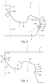
- Figure 1 shows a floor panel (1), comprising a first coupling part (2) and a second coupling part (3) in coupled condition.
- the first coupling part (2) comprises an upward tongue (4), an upward flank (5) lying at a distance from the upward tongue (4) and an upward groove (6) formed in between the upward tongue (4) and the upward flank (5), wherein the upward groove (6) adapted the downward tongue (7) of a second coupling part (3) of another panel (1).
- the side of the upward tongue (4) facing towards the upward flank is the inside (8) of the upward tongue (4) and the side of the upward tongue (4) facing away from the upward flank (5) is the outside (9) of the upward tongue (4).
- the second coupling part (3) comprises a downward tongue (7), a downward flank (10) lying at a distance from the downward tongue (7), and a downward groove (11) formed in between the downward tongue (7) and the downward flank (10).
- the side of the downward tongue (7) facing towards the downward flank (10) is the inside (12) of the downward tongue (7) and the side of the downward tongue (7) facing away from the downward flank (10) is the outside (13) of the downward tongue (7).
- the upper contact surface (14) and the inclined contact surface (15) of the upward flank (5) mutually enclose a first angle of about 125 degrees
- the upper contact surface (14) and the inclined contact surface (15) of the downward tongue (7) mutually enclose a second angle of about 125 degrees.
- Adjoining the inclined contact surface (15) the downward tongue (7) comprises an outer surface (16), and adjoining the inclined contact surface (15) the upward flank (5) comprises an inner surface (17), wherein the outer (16) and inner (17) surface are parallel and vertical. Between the outer surface (16) and the inner surface (17) a space (18) is present.
- the upper contact surfaces (14) define an inner vertical plane (19), wherein the inclined contact surface (15) of the downward tongue (7) extends beyond the inner vertical plane (19) the inclined contact surface (15) of the upward flank (5) lies inward compared to the inner vertical plane (19).
- a portion (20) of the downward tongue (7) extends beyond the inner vertical plane (19), wherein said portion (20) is substantially trapezium-shaped or wedge-shaped.
- the inclined contact surfaces (15) are both arranged completely outside and adjoining the inner vertical plane (19).
- the portion (20) is elongated with a larger vertical portion compared to the horizontal portion.
- the bottom (21) of the downward tongue (7) contacts the upper side (22) of the upward groove (6) at a groove contact surface (23), wherein a gap (24) is present between the first (2) and second (3) coupling parts, extending from the inclined contact surfaces (15) to the groove contact surface (23). Additionally the upper surface (25) of the upward tongue (4) and the upper surface (26) of the downward groove (11), are distanced from each other such that a gap (27) is present between the two surfaces (25, 26).
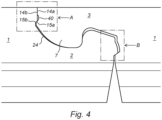
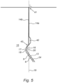
- Figures 2 and 3 show the first and second coupling parts individually.
- the outside of the outward bulge (28) comprises an upper portion (31) and an adjoining lower portion (32), wherein the lower portion (32) comprises an inclined locking surface (30a) and the upper portion (31) comprises a curved, guiding surface (32').
- the recess (29) comprises an upper portion (33) and an adjoining lower portion (34), wherein the lower portion comprises an inclined locking surface (30B).
- the upper portion (31, 33) extends over a larger vertical section compared to the lower portion (32, 34).
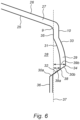
- Figure 6 schematically shows a detailed view of part B of the embodiment shown in figure 4 of and around the interlocking elements (28,29) of two interconnected panels.
Landscapes
- Engineering & Computer Science (AREA)
- Architecture (AREA)
- Civil Engineering (AREA)
- Structural Engineering (AREA)
- Floor Finish (AREA)
- Finishing Walls (AREA)
- Superstructure Of Vehicle (AREA)
Applications Claiming Priority (6)
| Application Number | Priority Date | Filing Date | Title |
|---|---|---|---|
| NL2026188A NL2026188B1 (en) | 2020-07-31 | 2020-07-31 | Panel, covering, and method of uncoupling two interconnected panels |
| NL2026190A NL2026190B1 (en) | 2020-07-31 | 2020-07-31 | Panel and covering |
| NL2026559 | 2020-09-28 | ||
| PCT/EP2021/070758 WO2022023224A1 (en) | 2020-07-31 | 2021-07-23 | Panel, covering, and method of uncoupling two interconnected panels |
| PCT/EP2021/070964 WO2022023319A1 (en) | 2020-07-31 | 2021-07-27 | Panel and covering |
| EP21749213.1A EP4189192B1 (de) | 2020-07-31 | 2021-07-27 | Paneel und belag |
Related Parent Applications (1)
| Application Number | Title | Priority Date | Filing Date |
|---|---|---|---|
| EP21749213.1A Division EP4189192B1 (de) | 2020-07-31 | 2021-07-27 | Paneel und belag |
Publications (2)
| Publication Number | Publication Date |
|---|---|
| EP4512976A2 true EP4512976A2 (de) | 2025-02-26 |
| EP4512976A3 EP4512976A3 (de) | 2025-05-07 |
Family
ID=77168276
Family Applications (2)
| Application Number | Title | Priority Date | Filing Date |
|---|---|---|---|
| EP24218099.0A Pending EP4512976A3 (de) | 2020-07-31 | 2021-07-27 | Paneel und belag |
| EP21749213.1A Active EP4189192B1 (de) | 2020-07-31 | 2021-07-27 | Paneel und belag |
Family Applications After (1)
| Application Number | Title | Priority Date | Filing Date |
|---|---|---|---|
| EP21749213.1A Active EP4189192B1 (de) | 2020-07-31 | 2021-07-27 | Paneel und belag |
Country Status (22)
| Country | Link |
|---|---|
| US (1) | US20230304300A1 (de) |
| EP (2) | EP4512976A3 (de) |
| JP (1) | JP2023540172A (de) |
| KR (1) | KR20230049655A (de) |
| CN (1) | CN116096975A (de) |
| AU (1) | AU2021314820A1 (de) |
| BR (1) | BR112023000412A2 (de) |
| CA (1) | CA3184201A1 (de) |
| DK (1) | DK4189192T3 (de) |
| ES (1) | ES3015470T3 (de) |
| FI (1) | FI4189192T3 (de) |
| HR (1) | HRP20250265T1 (de) |
| HU (1) | HUE070373T2 (de) |
| LT (1) | LT4189192T (de) |
| MX (1) | MX2023001168A (de) |
| PL (1) | PL4189192T3 (de) |
| PT (1) | PT4189192T (de) |
| RS (1) | RS66594B1 (de) |
| SI (1) | SI4189192T1 (de) |
| TW (1) | TW202208735A (de) |
| WO (1) | WO2022023319A1 (de) |
| ZA (1) | ZA202300965B (de) |
Families Citing this family (2)
| Publication number | Priority date | Publication date | Assignee | Title |
|---|---|---|---|---|
| BE1028427B1 (nl) * | 2020-06-24 | 2022-02-01 | Flooring Ind Ltd Sarl | Vloerpanelen en werkwijze voor het vervaardigen van vloerpanelen en snijgereedschappen hierbij aangewend |
| NL2026858B1 (en) * | 2020-11-09 | 2022-06-27 | I4F Licensing Nv | Decorative panel, and covering of such decorative panels |
Citations (4)
| Publication number | Priority date | Publication date | Assignee | Title |
|---|---|---|---|---|
| EP3031998A1 (de) | 2014-12-08 | 2016-06-15 | Akzenta Paneele + Profile GmbH | Paneel mit einem hakenförmigen Verriegelungssystem |
| WO2017115202A1 (en) | 2015-12-31 | 2017-07-06 | Flooring Industries Limited, Sarl | Floor panel for forming a floor covering |
| US20180094441A1 (en) | 2016-09-30 | 2018-04-05 | Valinge Innovation Ab | Set of panels |
| WO2019137964A1 (en) | 2018-01-09 | 2019-07-18 | Innovations4Flooring Holding N.V. | Panel |
Family Cites Families (14)
| Publication number | Priority date | Publication date | Assignee | Title |
|---|---|---|---|---|
| DE50309830D1 (de) * | 2002-11-15 | 2008-06-26 | Flooring Technologies Ltd | Einrichtung bestehend aus zwei miteinander verbindbaren Bauplatten und einem Einsatz zum Verriegeln dieser Bauplatten |
| DE202007018662U1 (de) * | 2007-03-26 | 2009-02-19 | Kronotec Ag | Paneel, insbesondere Bodenpaneel |
| DK2339092T3 (da) * | 2009-12-22 | 2019-07-22 | Flooring Ind Ltd Sarl | Fremgangsmåde til fremstilling af belægningspaneler |
| DE202011110452U1 (de) * | 2011-01-28 | 2014-02-11 | Akzenta Paneele + Profile Gmbh | Paneel |
| CN104870726B (zh) * | 2012-09-19 | 2017-11-07 | 依诺泰克环球有限公司 | 饰面板材及相关锁扣系统 |
| EP2754772A1 (de) * | 2013-01-11 | 2014-07-16 | Spanolux N.V. Div. Balterio | Bodenplattenanordnung, Bodenplatte und Verbindungselemente zur Verwendung damit |
| FR3024990B1 (fr) * | 2014-08-25 | 2018-11-16 | Gerflor | Panneau de sol pour la realisation d'un revetement. |
| BE1022985B1 (nl) * | 2015-01-16 | 2016-10-27 | Flooring Industries Limited Sarl | Vloerpaneel voor het vormen van een vloerbekleding |
| WO2016113677A1 (en) * | 2015-01-16 | 2016-07-21 | Flooring Industries Limited, Sarl | Floor panel for forming a floor covering |
| MX2018007995A (es) * | 2015-12-31 | 2019-01-10 | Flooring Ind Ltd Sarl | Panel de piso para formar un recubrimiento de piso. |
| US11015351B2 (en) * | 2017-03-21 | 2021-05-25 | Flooring Industries Limited, Sarl | Floor panel for forming a floor covering |
| WO2019138365A1 (en) * | 2018-01-11 | 2019-07-18 | Flooring Industries Limited, Sarl | Set of floor panels and method for installing this set of floor panels |
| FR3089534B1 (fr) * | 2018-12-07 | 2023-03-03 | Gerflor | Panneau a assemblage vertical pour la realisation d’un revêtement |
| BE1027299B1 (nl) * | 2019-05-22 | 2020-12-22 | Flooring Ind Ltd Sarl | Vloerpaneel voor het vormen van een vloerbekleding |
-
2021
- 2021-07-27 CA CA3184201A patent/CA3184201A1/en active Pending
- 2021-07-27 HU HUE21749213A patent/HUE070373T2/hu unknown
- 2021-07-27 RS RS20250223A patent/RS66594B1/sr unknown
- 2021-07-27 PL PL21749213.1T patent/PL4189192T3/pl unknown
- 2021-07-27 BR BR112023000412A patent/BR112023000412A2/pt unknown
- 2021-07-27 ES ES21749213T patent/ES3015470T3/es active Active
- 2021-07-27 MX MX2023001168A patent/MX2023001168A/es unknown
- 2021-07-27 LT LTEPPCT/EP2021/070964T patent/LT4189192T/lt unknown
- 2021-07-27 AU AU2021314820A patent/AU2021314820A1/en active Pending
- 2021-07-27 JP JP2023506255A patent/JP2023540172A/ja active Pending
- 2021-07-27 PT PT217492131T patent/PT4189192T/pt unknown
- 2021-07-27 DK DK21749213.1T patent/DK4189192T3/da active
- 2021-07-27 HR HRP20250265TT patent/HRP20250265T1/hr unknown
- 2021-07-27 EP EP24218099.0A patent/EP4512976A3/de active Pending
- 2021-07-27 EP EP21749213.1A patent/EP4189192B1/de active Active
- 2021-07-27 FI FIEP21749213.1T patent/FI4189192T3/fi active
- 2021-07-27 SI SI202130284T patent/SI4189192T1/sl unknown
- 2021-07-27 WO PCT/EP2021/070964 patent/WO2022023319A1/en not_active Ceased
- 2021-07-27 CN CN202180058263.6A patent/CN116096975A/zh active Pending
- 2021-07-27 US US18/018,714 patent/US20230304300A1/en active Pending
- 2021-07-27 KR KR1020237006451A patent/KR20230049655A/ko active Pending
- 2021-08-02 TW TW110128359A patent/TW202208735A/zh unknown
-
2023
- 2023-01-23 ZA ZA2023/00965A patent/ZA202300965B/en unknown
Patent Citations (4)
| Publication number | Priority date | Publication date | Assignee | Title |
|---|---|---|---|---|
| EP3031998A1 (de) | 2014-12-08 | 2016-06-15 | Akzenta Paneele + Profile GmbH | Paneel mit einem hakenförmigen Verriegelungssystem |
| WO2017115202A1 (en) | 2015-12-31 | 2017-07-06 | Flooring Industries Limited, Sarl | Floor panel for forming a floor covering |
| US20180094441A1 (en) | 2016-09-30 | 2018-04-05 | Valinge Innovation Ab | Set of panels |
| WO2019137964A1 (en) | 2018-01-09 | 2019-07-18 | Innovations4Flooring Holding N.V. | Panel |
Also Published As
| Publication number | Publication date |
|---|---|
| HUE070373T2 (hu) | 2025-06-28 |
| DK4189192T3 (da) | 2025-03-10 |
| JP2023540172A (ja) | 2023-09-22 |
| HRP20250265T1 (hr) | 2025-05-23 |
| BR112023000412A2 (pt) | 2023-02-07 |
| CA3184201A1 (en) | 2022-02-03 |
| ZA202300965B (en) | 2023-09-27 |
| EP4189192B1 (de) | 2024-12-11 |
| LT4189192T (lt) | 2025-04-10 |
| PL4189192T3 (pl) | 2025-04-22 |
| WO2022023319A1 (en) | 2022-02-03 |
| RS66594B1 (sr) | 2025-04-30 |
| US20230304300A1 (en) | 2023-09-28 |
| FI4189192T3 (fi) | 2025-03-14 |
| ES3015470T3 (en) | 2025-05-05 |
| TW202208735A (zh) | 2022-03-01 |
| EP4512976A3 (de) | 2025-05-07 |
| EP4189192A1 (de) | 2023-06-07 |
| MX2023001168A (es) | 2023-02-22 |
| AU2021314820A1 (en) | 2023-03-02 |
| KR20230049655A (ko) | 2023-04-13 |
| PT4189192T (pt) | 2025-03-10 |
| SI4189192T1 (sl) | 2025-04-30 |
| CN116096975A (zh) | 2023-05-09 |
Similar Documents
| Publication | Publication Date | Title |
|---|---|---|
| EP4189193B1 (de) | Paneel und abdeckung | |
| AU2021375354B2 (en) | Decorative panel, and covering of such decorative panels | |
| EP4189192B1 (de) | Paneel und belag | |
| US20260028830A1 (en) | Panel Suitable as a Floor, Ceiling or Wall Covering, and Covering for a Floor, Ceiling or Wall, Which is Constituted by a Multitude of Such Panels | |
| US20260035933A1 (en) | Panel and Covering | |
| US20230304301A1 (en) | Panel, Covering, and Method of Uncoupling Two Interconnected Panels | |
| NL2026190B1 (en) | Panel and covering | |
| NL2026191B1 (en) | Panel and covering | |
| HK40110797A (en) | Panel and covering | |
| HK40092887A (zh) | 镶板和覆盖物 | |
| EA045402B1 (ru) | Панель и покрытие |
Legal Events
| Date | Code | Title | Description |
|---|---|---|---|
| PUAI | Public reference made under article 153(3) epc to a published international application that has entered the european phase |
Free format text: ORIGINAL CODE: 0009012 |
|
| STAA | Information on the status of an ep patent application or granted ep patent |
Free format text: STATUS: REQUEST FOR EXAMINATION WAS MADE |
|
| 17P | Request for examination filed |
Effective date: 20241206 |
|
| AC | Divisional application: reference to earlier application |
Ref document number: 4189192 Country of ref document: EP Kind code of ref document: P |
|
| AK | Designated contracting states |
Kind code of ref document: A2 Designated state(s): AL AT BE BG CH CY CZ DE DK EE ES FI FR GB GR HR HU IE IS IT LI LT LU LV MC MK MT NL NO PL PT RO RS SE SI SK SM TR |
|
| REG | Reference to a national code |
Ref country code: DE Ref legal event code: R079 Free format text: PREVIOUS MAIN CLASS: E04F0015100000 Ipc: E04F0015020000 |
|
| PUAL | Search report despatched |
Free format text: ORIGINAL CODE: 0009013 |
|
| STAA | Information on the status of an ep patent application or granted ep patent |
Free format text: STATUS: EXAMINATION IS IN PROGRESS |
|
| AK | Designated contracting states |
Kind code of ref document: A3 Designated state(s): AL AT BE BG CH CY CZ DE DK EE ES FI FR GB GR HR HU IE IS IT LI LT LU LV MC MK MT NL NO PL PT RO RS SE SI SK SM TR |
|
| RIC1 | Information provided on ipc code assigned before grant |
Ipc: E04F 15/10 20060101ALI20250331BHEP Ipc: E04F 15/02 20060101AFI20250331BHEP |
|
| 17Q | First examination report despatched |
Effective date: 20250416 |
|
| RAV | Requested validation state of the european patent: fee paid |
Extension state: KH Effective date: 20250630 |