EP4512759A1 - Vorrichtung, verfahren zur überwachung des zustands eines stockwerk- und kabinentürkreises sowie aufzugssystem - Google Patents
Vorrichtung, verfahren zur überwachung des zustands eines stockwerk- und kabinentürkreises sowie aufzugssystem Download PDFInfo
- Publication number
- EP4512759A1 EP4512759A1 EP24193975.0A EP24193975A EP4512759A1 EP 4512759 A1 EP4512759 A1 EP 4512759A1 EP 24193975 A EP24193975 A EP 24193975A EP 4512759 A1 EP4512759 A1 EP 4512759A1
- Authority
- EP
- European Patent Office
- Prior art keywords
- door lock
- lock switch
- car door
- connection state
- landing
- Prior art date
- Legal status (The legal status is an assumption and is not a legal conclusion. Google has not performed a legal analysis and makes no representation as to the accuracy of the status listed.)
- Granted
Links
Images


Classifications
-
- B—PERFORMING OPERATIONS; TRANSPORTING
- B66—HOISTING; LIFTING; HAULING
- B66B—ELEVATORS; ESCALATORS OR MOVING WALKWAYS
- B66B13/00—Doors, gates, or other apparatus controlling access to, or exit from, cages or lift well landings
- B66B13/22—Operation of door or gate contacts
-
- B—PERFORMING OPERATIONS; TRANSPORTING
- B66—HOISTING; LIFTING; HAULING
- B66B—ELEVATORS; ESCALATORS OR MOVING WALKWAYS
- B66B5/00—Applications of checking, fault-correcting, or safety devices in elevators
- B66B5/0006—Monitoring devices or performance analysers
- B66B5/0018—Devices monitoring the operating condition of the elevator system
- B66B5/0031—Devices monitoring the operating condition of the elevator system for safety reasons
Definitions
- the present application relates to elevator technology and, in particular, to a device and method for monitoring a state of a landing and car door circuit, an elevator system comprising the device, and a non-transitory computer-readable storage medium for implementing the method.
- An elevator system typically includes a car door lock switch and a plurality of landing door lock switches, wherein the car door lock switch is mounted at the car, the number of which usually depends on the number of car doors, and each landing door lock switch is mounted at a corresponding landing door. These switches are coupled together in series to form a landing and car door circuit.
- the car door lock switch and the landing door lock switches are in a closed state; when the car stops at a floor and the landing door and car door are opened, the car door lock switch and the landing door lock switch of the corresponding floor are in an opened state.
- a device for monitoring a state of a landing and car door circuit comprising a first landing door lock switch, a second landing door lock switch, a first car door lock switch and a second car door lock switch sequentially coupled in series, the device comprising:
- the selecting unit comprises:
- an elevator system comprising:
- first and second do not indicate the order of the units in terms of time, space, size, etc., but are merely used to distinguish the units.
- contact switch refers to a switching element that utilizes conductive contacts to perform functions such as opening or closing a circuit, interrupting current, or causing current to flow to other circuits.
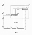
- FIG. 1 is a schematic diagram of a device for monitoring a state of a landing and car door circuit in accordance with some embodiments of the present application.
- a landing and car door circuit L being monitored includes first landing door lock switches DS 1 to DS n , second landing door lock switches RDS 1 to RDS n , a first car door lock switch GS and a second car door lock switch RGS, which are coupled together in series.
- the first landing door lock switches DS 1 to DS n are used as landing door lock switches equipped for front landing doors
- the second landing door lock switches RDS 1 to RDS n are used as landing door lock switches equipped for rear landing doors
- the first car door lock switch GS is used as a car door lock switch equipped for a front car door
- the second car door lock switch RGS is used as a car door lock switch equipped for a rear car door.
- the number of the first and second landing door lock switches usually depends on the number of floors, and the number of the car door lock switches depends on the number of car doors. It also should be noted that the order of the door lock switches in the landing and car door circuit L shown in FIG. 1 is only exemplary, and that the positions of the first landing door lock switches DS 1 to DS n and the second landing door lock switches RDS 1 to RDS n may be interchanged, and that the positions of the first car door lock switch GS and the second car door lock switch RGS may also be interchanged.
- a device 10 for monitoring a state of the landing and car door circuit includes a selecting unit 110 and a processing unit 120.
- the selecting unit 110 is connected to the landing and car door circuit L.
- one end of the selecting unit 110 is coupled with a (AC or DC) power supply V, and the other end is selectively coupled with the second car door lock switch RGS (shown by a solid line), or coupled to a common contact point A between the second landing door lock switch RDS n and the first car door lock switch GS (shown by a dotted line).
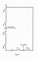
- the selecting unit 110 has a first connection state and a second connection state, wherein in the first connection state, as shown in FIG. 2A , the selecting unit 110 couples the second car door lock switch RGS with the power supply V, such that the first landing door lock switch DS 1 and the second car door lock switch RGS are coupled to, or connected in parallel to, the power supply V; in the second connection state, as shown in FIG. 2B , the selecting unit 110 couples the power supply V with the common contact point A of the second landing door lock switch RDS n and the first car door lock switch GS, i.e., such that the second landing door lock switch RDS n and the first car door lock switch GS are connected in parallel to the power supply V.
- the processing unit 120 is coupled with the selecting unit 110 and configured to control a connection state in which the selecting unit 110 is in when a car stops at a floor or when a landing door and a car door are opened, e.g., as shown in FIG. 1 , the processing unit 120 controls the selecting unit 110 by means of a control signal CTRL so that the selecting unit 110 is in the first connection state or the second connection state.
- the processing unit 120 also obtains a level signal DS_CHECK from a common contact point B between the first landing door lock switches DS T to DS n and the second landing door lock switches RDS 1 to RDS n (i.e., between the landing door lock switch DS n and the landing door lock switch RDS 1 ), obtains a level signal GS_CHECK from a common contact point C between the first car door lock switch GS and the second car door lock switch RGS, and determines whether functions of the first landing door lock switches DS 1 to DS n , the second landing door lock switches ROS 1 to RDS n , the first car door lock switch GS and the second car door lock switch RGS are normal based on levels of the level signal DS_CHECK and the level signal GS_CHECK.
- the first landing door lock switch DS 1 and the second car door lock switch RGS are coupled to or connected in parallel to the power supply V. If the car stops at a floor or the landing door and the car door are opened, the car door lock switch and the landing door lock switch of the corresponding floor should be in an opened state. In this case, the landing and car door circuit L is in an opened state, thus the level signal DS_CHECK and the level signal GS_CHECK are in a low level state.
- the level signal DS_CHECK will be in a high level state, and therefore it can be judged that the function of the first landing door lock switch DS i is abnormal.
- the level signal GS_CHECK will be in a high level state, and therefore it can be judged that the function of the second car door lock switch RGS is abnormal.
- the second landing door lock switch RDS n and the first car door lock switch GS are connected in parallel to the power supply V via the common contact point A. If the car stops at a floor or the landing door and the car door are opened, the car door lock switch and the landing door lock switch of the corresponding floor should be in an opened state. In this case, the landing and car door circuit L is in an opened state, thus the level signal DS_CHECK and the level signal GS_CHECK are in a low level state.
- the processing unit 120 is also configured to have a detection function for the selecting unit 110. For example, as shown in FIG. 1 , the processing unit 120 may judge whether the function of the selecting unit is normal based on a state signal MSDM from the selecting unit 110.
Landscapes
- Maintenance And Inspection Apparatuses For Elevators (AREA)
Applications Claiming Priority (1)
| Application Number | Priority Date | Filing Date | Title |
|---|---|---|---|
| CN202311069400.3A CN119503565A (zh) | 2023-08-23 | 2023-08-23 | 用于监测厅轿门回路状态的装置、方法和电梯系统 |
Publications (2)
| Publication Number | Publication Date |
|---|---|
| EP4512759A1 true EP4512759A1 (de) | 2025-02-26 |
| EP4512759B1 EP4512759B1 (de) | 2026-03-04 |
Family
ID=92301119
Family Applications (1)
| Application Number | Title | Priority Date | Filing Date |
|---|---|---|---|
| EP24193975.0A Active EP4512759B1 (de) | 2023-08-23 | 2024-08-09 | Vorrichtung, verfahren zur überwachung des zustands eines stockwerk- und kabinentürkreises sowie aufzugssystem |
Country Status (3)
| Country | Link |
|---|---|
| US (1) | US20250066161A1 (de) |
| EP (1) | EP4512759B1 (de) |
| CN (1) | CN119503565A (de) |
Citations (3)
| Publication number | Priority date | Publication date | Assignee | Title |
|---|---|---|---|---|
| EP2671836A1 (de) * | 2011-02-02 | 2013-12-11 | Mitsubishi Electric Corporation | Sicherheitssteuervorrichtung für aufzüge |
| EP3342744A1 (de) * | 2016-12-29 | 2018-07-04 | KONE Corporation | Verfahren zur steuerung eines aufzugs und aufzug |
| CN110759198B (zh) * | 2019-09-30 | 2021-11-19 | 苏州汇川技术有限公司 | 电梯门锁开关短接检测方法、系统、设备及存储介质 |
-
2023
- 2023-08-23 CN CN202311069400.3A patent/CN119503565A/zh active Pending
-
2024
- 2024-08-09 EP EP24193975.0A patent/EP4512759B1/de active Active
- 2024-08-19 US US18/808,656 patent/US20250066161A1/en active Pending
Patent Citations (3)
| Publication number | Priority date | Publication date | Assignee | Title |
|---|---|---|---|---|
| EP2671836A1 (de) * | 2011-02-02 | 2013-12-11 | Mitsubishi Electric Corporation | Sicherheitssteuervorrichtung für aufzüge |
| EP3342744A1 (de) * | 2016-12-29 | 2018-07-04 | KONE Corporation | Verfahren zur steuerung eines aufzugs und aufzug |
| CN110759198B (zh) * | 2019-09-30 | 2021-11-19 | 苏州汇川技术有限公司 | 电梯门锁开关短接检测方法、系统、设备及存储介质 |
Also Published As
| Publication number | Publication date |
|---|---|
| CN119503565A (zh) | 2025-02-25 |
| EP4512759B1 (de) | 2026-03-04 |
| US20250066161A1 (en) | 2025-02-27 |
Similar Documents
| Publication | Publication Date | Title |
|---|---|---|
| US9053884B2 (en) | Safety switching device with universal signal input | |
| CN110007663A (zh) | 核安全级dcs的开关量输出动态诊断系统及方法 | |
| CN104101831A (zh) | 继电器故障检测系统 | |
| CN216718614U (zh) | 继电器状态测试装置及电气设备 | |
| JPH05280658A (ja) | 多重負荷を切り換える電子制御装置 | |
| CN101600609B (zh) | 带有电气控制的驻车制动器系统 | |
| EP4512759B1 (de) | Vorrichtung, verfahren zur überwachung des zustands eines stockwerk- und kabinentürkreises sowie aufzugssystem | |
| CN109229142B (zh) | 列车道岔控制系统及控制方法 | |
| CN109213010B (zh) | 一种具有优先级的继电器多路选择开关电路及测试系统 | |
| CN115195812B (zh) | 计轴复位控制系统及方法 | |
| CN119087206A (zh) | 与列车交互的继电器的故障检测方法以及系统 | |
| CN116068919B (zh) | 水表阀门控制设备、方法、电子设备及存储介质 | |
| JP2011248390A (ja) | 車両制御装置 | |
| CN114670894B (zh) | 一种全电子联锁道岔板一驱到底功能电路 | |
| CN215160058U (zh) | 厅门检测装置 | |
| CN110444444A (zh) | 驱动接触器的电路 | |
| KR100372761B1 (ko) | 엘리베이터 시스템의 도어상태 감시장치 및 그 방법과이를 이용하는 엘리베이터 제어기 | |
| CN109132813B (zh) | 电梯门电路及其短接检测方法 | |
| EP4389666A1 (de) | Vorrichtung und verfahren zur erkennung einer dichtungssternfunktion einer aufzuganlage | |
| CN116397969B (zh) | 车门儿童锁的控制方法及装置 | |
| EP4206106B1 (de) | Verfahren und vorrichtung zur erkennung einer aufzugssicherheitskette | |
| CN113371565B (zh) | 厅门检测装置及厅门检测方法 | |
| KR102930880B1 (ko) | 엘리베이터 카 위치추적 시스템 | |
| CN106486977B (zh) | 一种带积分自清除功能的特高压直流旁路开关保护方法 | |
| US20250153973A1 (en) | Elevator emergency operation device with safety function test |
Legal Events
| Date | Code | Title | Description |
|---|---|---|---|
| PUAI | Public reference made under article 153(3) epc to a published international application that has entered the european phase |
Free format text: ORIGINAL CODE: 0009012 |
|
| STAA | Information on the status of an ep patent application or granted ep patent |
Free format text: STATUS: THE APPLICATION HAS BEEN PUBLISHED |
|
| AK | Designated contracting states |
Kind code of ref document: A1 Designated state(s): AL AT BE BG CH CY CZ DE DK EE ES FI FR GB GR HR HU IE IS IT LI LT LU LV MC ME MK MT NL NO PL PT RO RS SE SI SK SM TR |
|
| STAA | Information on the status of an ep patent application or granted ep patent |
Free format text: STATUS: REQUEST FOR EXAMINATION WAS MADE |
|
| 17P | Request for examination filed |
Effective date: 20250722 |
|
| GRAP | Despatch of communication of intention to grant a patent |
Free format text: ORIGINAL CODE: EPIDOSNIGR1 |
|
| STAA | Information on the status of an ep patent application or granted ep patent |
Free format text: STATUS: GRANT OF PATENT IS INTENDED |
|
| RIC1 | Information provided on ipc code assigned before grant |
Ipc: B66B 5/00 20060101AFI20250911BHEP Ipc: B66B 13/22 20060101ALI20250911BHEP |
|
| INTG | Intention to grant announced |
Effective date: 20251013 |
|
| RIN1 | Information on inventor provided before grant (corrected) |
Inventor name: SUN, XINGZHONG Inventor name: LI, SHAN Inventor name: DAI, WEILIN |
|
| GRAS | Grant fee paid |
Free format text: ORIGINAL CODE: EPIDOSNIGR3 |
|
| GRAA | (expected) grant |
Free format text: ORIGINAL CODE: 0009210 |
|
| STAA | Information on the status of an ep patent application or granted ep patent |
Free format text: STATUS: THE PATENT HAS BEEN GRANTED |
|
| AK | Designated contracting states |
Kind code of ref document: B1 Designated state(s): AL AT BE BG CH CY CZ DE DK EE ES FI FR GB GR HR HU IE IS IT LI LT LU LV MC ME MK MT NL NO PL PT RO RS SE SI SK SM TR |
|
| REG | Reference to a national code |
Ref country code: CH Ref legal event code: F10 Free format text: ST27 STATUS EVENT CODE: U-0-0-F10-F00 (AS PROVIDED BY THE NATIONAL OFFICE) Effective date: 20260304 Ref country code: GB Ref legal event code: FG4D |
|
| REG | Reference to a national code |
Ref country code: DE Ref legal event code: R096 Ref document number: 602024002968 Country of ref document: DE |
|
| REG | Reference to a national code |
Ref country code: IE Ref legal event code: FG4D |