EP4512748A1 - Palettensystem - Google Patents
Palettensystem Download PDFInfo
- Publication number
- EP4512748A1 EP4512748A1 EP24188357.8A EP24188357A EP4512748A1 EP 4512748 A1 EP4512748 A1 EP 4512748A1 EP 24188357 A EP24188357 A EP 24188357A EP 4512748 A1 EP4512748 A1 EP 4512748A1
- Authority
- EP
- European Patent Office
- Prior art keywords
- pallet
- load
- conveyor
- width
- support surface
- Prior art date
- Legal status (The legal status is an assumption and is not a legal conclusion. Google has not performed a legal analysis and makes no representation as to the accuracy of the status listed.)
- Granted
Links
Images


Classifications
-
- B—PERFORMING OPERATIONS; TRANSPORTING
- B65—CONVEYING; PACKING; STORING; HANDLING THIN OR FILAMENTARY MATERIAL
- B65G—TRANSPORT OR STORAGE DEVICES, e.g. CONVEYORS FOR LOADING OR TIPPING, SHOP CONVEYOR SYSTEMS OR PNEUMATIC TUBE CONVEYORS
- B65G37/00—Combinations of mechanical conveyors of the same kind, or of different kinds, of interest apart from their application in particular machines or use in particular manufacturing processes
- B65G37/005—Combinations of mechanical conveyors of the same kind, or of different kinds, of interest apart from their application in particular machines or use in particular manufacturing processes comprising two or more co-operating conveying elements with parallel longitudinal axes
-
- B—PERFORMING OPERATIONS; TRANSPORTING
- B65—CONVEYING; PACKING; STORING; HANDLING THIN OR FILAMENTARY MATERIAL
- B65G—TRANSPORT OR STORAGE DEVICES, e.g. CONVEYORS FOR LOADING OR TIPPING, SHOP CONVEYOR SYSTEMS OR PNEUMATIC TUBE CONVEYORS
- B65G13/00—Roller-ways
- B65G13/11—Roller frames
-
- B—PERFORMING OPERATIONS; TRANSPORTING
- B65—CONVEYING; PACKING; STORING; HANDLING THIN OR FILAMENTARY MATERIAL
- B65G—TRANSPORT OR STORAGE DEVICES, e.g. CONVEYORS FOR LOADING OR TIPPING, SHOP CONVEYOR SYSTEMS OR PNEUMATIC TUBE CONVEYORS
- B65G47/00—Article or material-handling devices associated with conveyors; Methods employing such devices
- B65G47/52—Devices for transferring articles or materials between conveyors i.e. discharging or feeding devices
-
- B—PERFORMING OPERATIONS; TRANSPORTING
- B65—CONVEYING; PACKING; STORING; HANDLING THIN OR FILAMENTARY MATERIAL
- B65G—TRANSPORT OR STORAGE DEVICES, e.g. CONVEYORS FOR LOADING OR TIPPING, SHOP CONVEYOR SYSTEMS OR PNEUMATIC TUBE CONVEYORS
- B65G65/00—Loading or unloading
-
- B—PERFORMING OPERATIONS; TRANSPORTING
- B66—HOISTING; LIFTING; HAULING
- B66F—HOISTING, LIFTING, HAULING OR PUSHING, NOT OTHERWISE PROVIDED FOR, e.g. DEVICES WHICH APPLY A LIFTING OR PUSHING FORCE DIRECTLY TO THE SURFACE OF A LOAD
- B66F9/00—Devices for lifting or lowering bulky or heavy goods for loading or unloading purposes
- B66F9/06—Devices for lifting or lowering bulky or heavy goods for loading or unloading purposes movable, with their loads, on wheels or the like, e.g. fork-lift trucks
- B66F9/063—Automatically guided
Definitions
- the invention relates to a pallet system for transferring a load from a pallet to a conveyor, the pallet system comprising a load, a pallet for holding the load thereon, a transport device with a lifting device for vertical and horizontal movement of the pallet, and a conveyor for the load.
- JP H08 2650 A discloses a pallet system for unloading a pallet having a load thereon from a carriage onto a conveyor device according to the preamble of claim 1.
- a disadvantage of the current pallet systems is that in order to transfer a load from a pallet to a conveyor, and thereby separating the load from the pallet, a further transferring device or technique is needed. Pallet unloading is generally performed by gripping the load from above or from the side, for example by a pick-up device or human operator, such that the load is transferred to the conveyor. This system of separating results in the use of extra manpower or equipment, increasing the costs and slowing down the transferring process.
- the invention provides a pallet system for transferring a load from a pallet to a conveyor, the pallet system comprising:
- the load is transferred from the pallet to the conveyor device by the transport device without the need of a pick-up device or a human being.
- the load is transferred to the conveyor device, and the pallet can directly be moved away from below the load by the transport device. This makes transferring the load from the pallet to the conveyor device, in for example a warehouse, easier, faster, less complex, and cheaper.
- the load receiving surface has a rectangular outline.
- the left projecting distance is at least 5% of the load width, and wherein the right projecting distance is at least 5% of the load width.
- the left upwardly directed support surface has a left conveyor width
- the right upwardly directed support surface has a right conveyor width
- the left conveyor width is at least 5% of the load width
- the right conveyor width is at least 5% of the load width
- the load width minus the pallet pass-through opening width is at least 10% of the load width
- the pallet width is at least 50% of the load width.
- the left conveyor and the right conveyor are roller conveyors.
- left upwardly directed support surface and the right upwardly directed support surface are horizontally arranged.
- the left upwardly directed support surface and the right upwardly directed support surface are arranged at an inclination angle.
- the left upwardly directed support surface and the right upwardly directed support surface slope downwards away from the receiving end.
- the transport device is an automated guided vehicle or forklift.
- the load has a bottom wall, a left side wall, a right side wall opposite the left side wall, a front wall, and a back wall opposite the front wall.
- the load further has a top wall opposite the bottom wall.
- the load is a cardboard box.
- the invention provides a method for transferring a load from a pallet to a conveyor using a pallet system according to any of the preceding claims, wherein the method comprises
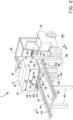
- FIG. 1-5 A schematic overview of a pallet system 1 according to a first embodiment of the invention is shown in Figures 1-5 .
- the pallet system 1 comprises a load 10, a pallet 20, a transport device 30 and a conveyor 40.
- the load 10 is a rectangular-shaped box that comprises a bottom wall 12, a left side wall 13, a right side wall 14 opposite the left side wall 13, a front wall 15, a back wall 16 opposite the front wall 15, and, optionally, a top wall 11 opposite the bottom wall 12.
- the load 10 has a load length L1 between the front wall 15 and the back wall 16, a load width W1 between the left side wall 13 and the right side wall 14, and a load height H1 between the bottom wall 12 and the top wall 11.
- the top slats 21 define a load receiving surface 24 with a rectangular outline for receiving the load 10 thereon.
- the pallet 20 has a pallet width W2, which corresponds to the length of the top slats 21, a pallet height, which is the combined height of the supporting structure 22 and the top slat 21, and a pallet length L2, which corresponds to the length of the supporting structures 22.
- the load 10 is positioned on the pallet 20 by arranging the bottom wall 12 of the load 10 on the load receiving surface 24 of the pallet 20.
- the load 10 projects from the pallet 20 at both sides of the load receiving surface 24 in the longitudinal direction of the top slats 21.
- the load 10 projects from the pallet 20 at the left side wall 13 by a left projecting portion 17 having a left downwardly directed support surface 51 at the bottom wall 12.
- the left projecting portion 17 projects from the pallet 20 by a left projecting distance D1.
- the load 10 projects from the pallet 20 by a right projecting portion 18 having a right downwardly directed support surface 52 at the bottom wall 12.
- the right projecting portion 18 projects from the pallet 20 by a right projecting distance D2.
- the pallet system 1 further comprises a transport device, in this example an electrically driven forklift 30 that is adapted to drive over an underground 100.
- the forklift 30 comprises a forklift body 31, a mast 32 and a carriage 33.
- the carriage 33 is displaceable in a vertical displacement direction or lifting direction V along the mast 32.
- the carriage 33 comprises a fork 34 with two horizontal arranged fork teeth 35.
- the insertion channels 23 of the pallet 20 are configured for receiving the fork teeth 35 of the forklift 30 therein.
- the fork teeth 35 have a fork teeth height that is smaller than the insertion channel height H3 and a fork teeth width that is smaller than the insertion channel width W3, such that the fork teeth 35 can easily be inserted into the insertion channels 23 with margin.
- the forklift 30 is configured to hold the pallet 20 by inserting the two fork teeth 35 into the insertion channels 23 of the pallet 20 and lifting the fork 34 by displacing the carriage 33 upwards in the vertical lifting direction V along the mast
- the pallet system 1 further comprises a horizontally arranged conveyor 40 configured for receiving the load 10 at a receiving end 41 thereof and for transporting the load 10 away from the receiving end 41 in a transport direction T, for example, towards a non-shown delivery end.
- the conveyor 40 comprises a left roller conveyor 42 and a right roller conveyor 43. Both the left roller conveyor 42 and the right roller conveyor 43 comprise a horizontal beam 44 and multiple vertical beams 48, 49 that support the horizontal beams 44.
- the left roller conveyor 42 and the right roller conveyor 43 are spaced from each other so as to create a pallet pass-through opening 46 therebetween having an opening width W4, as best shown in Figures 1 and 3 .
- the left roller conveyor 42 and the right roller conveyor 43 are connected via a connecting beam 47.
- the horizontal beams 44 of the conveyor 40 are provided with rollers 50 thereon.
- Each roller 50 having a roll axis C around which the roller 50 can freely rotate.
- Multiple rollers 50 are arranged on each horizontal beam 44, wherein for each horizontal beam 44 the rollers 50 are arranged side by side with the roll axes C parallel to each other and horizontal arranged, and with the roll axes C being transverse to the longitudinal direction of the horizontal beams 44.
- the left roller conveyor 42 has a left upwardly directed support surface 53 that is formed by the upwardly facing parts of the outline of the rollers 50 that are arranged at the left conveyor 42.
- the left upwardly directed support surface 53 is configured to receive the left downwardly directed support surface 51 of the load 10 thereon.
- the right roller conveyor 43 has a right upwardly directed support surface 54 that is formed by the upwardly facing parts of the outline of the rollers 50 that are arranged at the right roller conveyor 43.
- the right upwardly directed support surface 54 is configured to receive the right downwardly directed support surface 52 of the load 10 thereon.
- Both the left roller conveyor 42, and the right roller conveyor 43 have a conveyor width W5 which corresponds to a length of each roller 50 in axial direction.
- This conveyor width W5 is also corresponding to the width of the left upwardly directed support surface 53 and the right upwardly directed support surface 54.
- the conveyor 40 is configured to receive the load 10 which is transported on the pallet 20 towards the conveyor 40 by the forklift 30.
- the pallet pass-through opening 46 has an opening length L4 extending from the receiving end 41 towards the connecting beam 47, wherein the opening length L4 is larger than the pallet length L2, so that the pallet 20 can be received in and pass through the pallet pass-through opening 46 between the connecting beam 47 and the receiving end 41.
- the opening width W4 is slightly wider than the pallet width W2, so that the pallet 20 can pass through the left roller conveyor 42 and the right roller conveyor 43 via the pallet pass-through opening 46 by margin.
- the conveyor 40 has a conveyor height H4, which conveyor height H4 is at least larger than the pallet height.
- Figure 1 shows the pallet system 1 in the situation wherein the load 10 is provided on the pallet 20, and wherein the pallet 20 is lifted high by the forklift 30.
- the pallet 20 is lifted to a height above the conveyor height H4.
- the forklift 30 drives over the underground 100 towards the conveyor 40 and is received by the conveyor 40 in a horizontal receiving direction R that is parallel to the transport direction T.
- the conveyor 40 is received at the receiving end 41 of the conveyor 40, such that the pallet 20 at the fork 34 of the forklift 30 is aligned with and positioned above the pallet pass-through opening 46, as shown in Figure 2 .
- the pallet 20 which is lifted by the forklift 30 is lowered in the vertical lifting direction V to a height below the conveyor height H4. Since the pallet width W2 is smaller than the opening width W4, the pallet 20 passes through the pallet pass-through opening 46, and since the load width W1 is larger than the opening width W4, the load 10 does not pass through the pallet pass-through opening 46. Therefore, the load 10 is transferred to the conveyor 40 on top of the rollers 50 thereof.
- the left downwardly directed support surface 51 of the load 10 corresponding to the left projecting portion 17 lands on top of the rollers 50 at the left conveyor 42 on the left upwardly directed support surface 53.
- the right downwardly directed support surface 52 of the load 10 lands on top of the rollers 50 at the right conveyor 43 on the right upwardly directed support surface 54.
- the pallet 20 without the load 10 remains at the fork 34 of the forklift 30, as shown in Figures 3 and 4 .
- the forklift 30 drives, over the underground 100, away from the conveyor 40.
- the conveyor 40 is configured for transporting the load 10, that is received thereon, away from the receiving end 41 in a transport direction T, for example towards the non-shown delivery end.
- the left projecting distance D1 of the left projecting portion 17 is at least 5% of the load width W1
- the right projecting distance D2 of the right projecting portion 18 is at least 5% of the load width W1.
- the left projecting distance D1 can differ from the right projecting distance D2.
- the pallet width W2 is at least 50% of the load width W1.
- the roller conveyor width W5 is in this example similar for the left roller conveyor 42 and the right roller conveyor 43, but the roller conveyor width W5 can be different for the left roller conveyor 42 and the right roller conveyor 43.
- the left roller conveyor width W5 and the right roller conveyor width W5 are each at least 5% of the load width W1. Further, the load width W1 minus the left roller conveyor width W5 and minus the right roller conveyor width W5 is at least 10% of the load width W1.
- the pallet width W2 is at least 50% of the load width W1.
- the pallet system 101 comprises a conveyor 140 that is inclined under an inclination angle A.
- An exemplary embodiment of this is shown in Figures 6 and 7 .
- the pallet system 101 comprises, except for some components of the conveyor and the conveyor itself, the same components as the pallet system according to the exemplary embodiment described before. Components that are different compared to the first exemplary embodiment are reintroduced and renumbered in the description and in Figures 6 and 7 .
- the horizontal beams 44 of the conveyor are supported by a first set of vertical beams 148 having a first beam height H41, and a second set of vertical beams 149 having a second beam height H42.
- the first beam height H41 is larger than the second beam height H42, resulting in the horizontal beams 44 being arranged under the inclination angle A.
- the load 10 is provided on the pallet 20, and the pallet 20 is lifted high by the forklift 30.
- the pallet 20 is lifted to a heigh above the first beam height H41.
- the forklift 30 drives over the underground 100 towards the conveyor 140 in the receiving direction R, such that the pallet 20 is aligned with and positioned above the pallet pass-through opening 46, as shown in Figure 6 .
- the pallet 20 which is lifted by the forklift 30 is lowered in the vertical lifting direction V to a height below the first beam height H41. Since the pallet width W2 is smaller than the opening width W4, the pallet passes through the pallet pass-through opening 46, and since the load width W1 is larger than the opening width W4, the load 10 does not pass through the pallet pass-through opening 46. Therefore, the load 10 is transferred to the conveyor 140 on top of the rollers 50 thereof.
- the load 10 tilts by its own weight until its bottom wall 12 is parallel to the transport direction TT of the conveyor 140, as shown in Figure 7 .
- the left projecting portion 17 lands on top of the rollers 50 arranged on the horizontal beam 44 of the left roller conveyor 42 and the right projecting portion 18 lands on top of the rollers 50 arranged on the horizontal beam 44 of the right roller conveyor 43.
- the pallet 20 without the load 10 remains on the fork 34 of the forklift 30.
- the forklift 30 drives over the underground 100, away from the conveyor 140.
- the conveyor 140 is configured for transporting the load 10 away from the receiving end 41 in a transport direction TT towards a non-shown delivery end.
Landscapes
- Engineering & Computer Science (AREA)
- Mechanical Engineering (AREA)
- Transportation (AREA)
- Structural Engineering (AREA)
- Civil Engineering (AREA)
- Life Sciences & Earth Sciences (AREA)
- Geology (AREA)
- Intermediate Stations On Conveyors (AREA)
- Warehouses Or Storage Devices (AREA)
Applications Claiming Priority (1)
| Application Number | Priority Date | Filing Date | Title |
|---|---|---|---|
| NL2035671A NL2035671B1 (en) | 2023-08-24 | 2023-08-24 | Pallet system |
Publications (3)
| Publication Number | Publication Date |
|---|---|
| EP4512748A1 true EP4512748A1 (de) | 2025-02-26 |
| EP4512748B1 EP4512748B1 (de) | 2025-12-31 |
| EP4512748C0 EP4512748C0 (de) | 2025-12-31 |
Family
ID=88207216
Family Applications (1)
| Application Number | Title | Priority Date | Filing Date |
|---|---|---|---|
| EP24188357.8A Active EP4512748B1 (de) | 2023-08-24 | 2024-07-12 | Palettensystem |
Country Status (2)
| Country | Link |
|---|---|
| EP (1) | EP4512748B1 (de) |
| NL (1) | NL2035671B1 (de) |
Citations (3)
| Publication number | Priority date | Publication date | Assignee | Title |
|---|---|---|---|---|
| JPH082650A (ja) | 1994-06-15 | 1996-01-09 | Mitsui Eng & Shipbuild Co Ltd | コンベヤの荷物先詰め方法およびアキュームレーションコンベヤシステム |
| EP4071089A1 (de) * | 2021-04-07 | 2022-10-12 | Interroll Holding AG | Fördereranordnung |
| EP4071093A1 (de) * | 2021-04-07 | 2022-10-12 | Interroll Holding AG | Dockstationsanordnung und verfahren zum überführen von gütern zwischen einer fördervorrichtung und einem transportfahrzeug |
-
2023
- 2023-08-24 NL NL2035671A patent/NL2035671B1/en active
-
2024
- 2024-07-12 EP EP24188357.8A patent/EP4512748B1/de active Active
Patent Citations (3)
| Publication number | Priority date | Publication date | Assignee | Title |
|---|---|---|---|---|
| JPH082650A (ja) | 1994-06-15 | 1996-01-09 | Mitsui Eng & Shipbuild Co Ltd | コンベヤの荷物先詰め方法およびアキュームレーションコンベヤシステム |
| EP4071089A1 (de) * | 2021-04-07 | 2022-10-12 | Interroll Holding AG | Fördereranordnung |
| EP4071093A1 (de) * | 2021-04-07 | 2022-10-12 | Interroll Holding AG | Dockstationsanordnung und verfahren zum überführen von gütern zwischen einer fördervorrichtung und einem transportfahrzeug |
Also Published As
| Publication number | Publication date |
|---|---|
| EP4512748B1 (de) | 2025-12-31 |
| EP4512748C0 (de) | 2025-12-31 |
| NL2035671B1 (en) | 2025-03-06 |
Similar Documents
| Publication | Publication Date | Title |
|---|---|---|
| CN106477217B (zh) | 物品搬运设备 | |
| JP2023517014A (ja) | 積み卸し装置、積み卸しシステム及び積み卸し方法 | |
| US4568231A (en) | Method and equipment for palletizing and depalletizing can-tops | |
| CN210084502U (zh) | 货物智能装卸系统 | |
| CN105151613A (zh) | 一种升降堆垛式自动立库 | |
| UA78784C2 (en) | System and method for applying loading ledges onto a unit load | |
| CN112124981B (zh) | 供料装置及其供料方法 | |
| CN113979154A (zh) | 一种平板车纸箱包装物料自动装车系统及装车方法 | |
| WO2025145869A1 (zh) | 一种自动化物料装车系统 | |
| KR20240032074A (ko) | 보관 보조물의 보관 또는 인출 방법 | |
| JP2692414B2 (ja) | トレーへの荷積み卸し設備 | |
| CN213801957U (zh) | 供料装置 | |
| CN111422412B (zh) | 一种可实现砌块与托板分离并对砌块进行码垛的生产线 | |
| CN111003440B (zh) | 输送设备 | |
| EP4512748A1 (de) | Palettensystem | |
| JP2000169018A (ja) | 第1のパレットの上にある枚葉紙パイルを別の第2のパレットに積み替える装置 | |
| JP2008024493A (ja) | 物品移載装置 | |
| CN114074852B (zh) | 一种笼车装笼装置及笼车装笼系统 | |
| CN215945979U (zh) | Agv输送设备及agv物流系统 | |
| CA2208512C (en) | A method and apparatus for handling sheet stacks | |
| JPH10181884A (ja) | 物品の段積方法およびその装置 | |
| CN111620013A (zh) | 堆垛机、取放设备和立体仓库 | |
| US12151899B2 (en) | Hauling transporter, hauling beam and method for loading | |
| CN214780516U (zh) | 一种自动装卸一体机 | |
| KR102736753B1 (ko) | 제품이 적재된 팰릿이 지면에 밀착되도록 배출이 준비되는 자동 적재장치 |
Legal Events
| Date | Code | Title | Description |
|---|---|---|---|
| PUAI | Public reference made under article 153(3) epc to a published international application that has entered the european phase |
Free format text: ORIGINAL CODE: 0009012 |
|
| STAA | Information on the status of an ep patent application or granted ep patent |
Free format text: STATUS: THE APPLICATION HAS BEEN PUBLISHED |
|
| AK | Designated contracting states |
Kind code of ref document: A1 Designated state(s): AL AT BE BG CH CY CZ DE DK EE ES FI FR GB GR HR HU IE IS IT LI LT LU LV MC ME MK MT NL NO PL PT RO RS SE SI SK SM TR |
|
| STAA | Information on the status of an ep patent application or granted ep patent |
Free format text: STATUS: REQUEST FOR EXAMINATION WAS MADE |
|
| 17P | Request for examination filed |
Effective date: 20250324 |
|
| GRAP | Despatch of communication of intention to grant a patent |
Free format text: ORIGINAL CODE: EPIDOSNIGR1 |
|
| STAA | Information on the status of an ep patent application or granted ep patent |
Free format text: STATUS: GRANT OF PATENT IS INTENDED |
|
| RIC1 | Information provided on ipc code assigned before grant |
Ipc: B66F 9/06 20060101ALI20250523BHEP Ipc: B65G 65/00 20060101ALI20250523BHEP Ipc: B65G 47/52 20060101ALI20250523BHEP Ipc: B65G 37/00 20060101ALI20250523BHEP Ipc: B65G 13/11 20060101AFI20250523BHEP |
|
| INTG | Intention to grant announced |
Effective date: 20250606 |
|
| GRAS | Grant fee paid |
Free format text: ORIGINAL CODE: EPIDOSNIGR3 |
|
| GRAA | (expected) grant |
Free format text: ORIGINAL CODE: 0009210 |
|
| STAA | Information on the status of an ep patent application or granted ep patent |
Free format text: STATUS: THE PATENT HAS BEEN GRANTED |
|
| AK | Designated contracting states |
Kind code of ref document: B1 Designated state(s): AL AT BE BG CH CY CZ DE DK EE ES FI FR GB GR HR HU IE IS IT LI LT LU LV MC ME MK MT NL NO PL PT RO RS SE SI SK SM TR |
|
| REG | Reference to a national code |
Ref country code: CH Ref legal event code: F10 Free format text: ST27 STATUS EVENT CODE: U-0-0-F10-F00 (AS PROVIDED BY THE NATIONAL OFFICE) Effective date: 20251231 Ref country code: GB Ref legal event code: FG4D |
|
| REG | Reference to a national code |
Ref country code: CH Ref legal event code: R17 Free format text: ST27 STATUS EVENT CODE: U-0-0-R10-R17 (AS PROVIDED BY THE NATIONAL OFFICE) Effective date: 20260109 |
|
| REG | Reference to a national code |
Ref country code: DE Ref legal event code: R096 Ref document number: 602024001919 Country of ref document: DE |
|
| U01 | Request for unitary effect filed |
Effective date: 20260106 |
|
| U07 | Unitary effect registered |
Designated state(s): AT BE BG DE DK EE FI FR IT LT LU LV MT NL PT RO SE SI Effective date: 20260113 |