EP4512649A1 - Vehicle instrument panel structure - Google Patents
Vehicle instrument panel structure Download PDFInfo
- Publication number
- EP4512649A1 EP4512649A1 EP24188931.0A EP24188931A EP4512649A1 EP 4512649 A1 EP4512649 A1 EP 4512649A1 EP 24188931 A EP24188931 A EP 24188931A EP 4512649 A1 EP4512649 A1 EP 4512649A1
- Authority
- EP
- European Patent Office
- Prior art keywords
- vehicle
- switch
- instrument panel
- disposed
- brake switch
- Prior art date
- Legal status (The legal status is an assumption and is not a legal conclusion. Google has not performed a legal analysis and makes no representation as to the accuracy of the status listed.)
- Pending
Links
- 230000007704 transition Effects 0.000 abstract description 9
- 210000003811 finger Anatomy 0.000 description 4
- 230000004048 modification Effects 0.000 description 3
- 238000012986 modification Methods 0.000 description 3
- 230000005540 biological transmission Effects 0.000 description 1
- 238000010586 diagram Methods 0.000 description 1
- 239000000428 dust Substances 0.000 description 1
- 230000000694 effects Effects 0.000 description 1
- 238000000034 method Methods 0.000 description 1
- 230000007935 neutral effect Effects 0.000 description 1
- 230000008929 regeneration Effects 0.000 description 1
- 238000011069 regeneration method Methods 0.000 description 1
- 210000003813 thumb Anatomy 0.000 description 1
Images




Classifications
-
- B—PERFORMING OPERATIONS; TRANSPORTING
- B60—VEHICLES IN GENERAL
- B60K—ARRANGEMENT OR MOUNTING OF PROPULSION UNITS OR OF TRANSMISSIONS IN VEHICLES; ARRANGEMENT OR MOUNTING OF PLURAL DIVERSE PRIME-MOVERS IN VEHICLES; AUXILIARY DRIVES FOR VEHICLES; INSTRUMENTATION OR DASHBOARDS FOR VEHICLES; ARRANGEMENTS IN CONNECTION WITH COOLING, AIR INTAKE, GAS EXHAUST OR FUEL SUPPLY OF PROPULSION UNITS IN VEHICLES
- B60K35/00—Instruments specially adapted for vehicles; Arrangement of instruments in or on vehicles
- B60K35/10—Input arrangements, i.e. from user to vehicle, associated with vehicle functions or specially adapted therefor
-
- B—PERFORMING OPERATIONS; TRANSPORTING
- B60—VEHICLES IN GENERAL
- B60K—ARRANGEMENT OR MOUNTING OF PROPULSION UNITS OR OF TRANSMISSIONS IN VEHICLES; ARRANGEMENT OR MOUNTING OF PLURAL DIVERSE PRIME-MOVERS IN VEHICLES; AUXILIARY DRIVES FOR VEHICLES; INSTRUMENTATION OR DASHBOARDS FOR VEHICLES; ARRANGEMENTS IN CONNECTION WITH COOLING, AIR INTAKE, GAS EXHAUST OR FUEL SUPPLY OF PROPULSION UNITS IN VEHICLES
- B60K35/00—Instruments specially adapted for vehicles; Arrangement of instruments in or on vehicles
- B60K35/20—Output arrangements, i.e. from vehicle to user, associated with vehicle functions or specially adapted therefor
- B60K35/21—Output arrangements, i.e. from vehicle to user, associated with vehicle functions or specially adapted therefor using visual output, e.g. blinking lights or matrix displays
- B60K35/22—Display screens
-
- B—PERFORMING OPERATIONS; TRANSPORTING
- B60—VEHICLES IN GENERAL
- B60K—ARRANGEMENT OR MOUNTING OF PROPULSION UNITS OR OF TRANSMISSIONS IN VEHICLES; ARRANGEMENT OR MOUNTING OF PLURAL DIVERSE PRIME-MOVERS IN VEHICLES; AUXILIARY DRIVES FOR VEHICLES; INSTRUMENTATION OR DASHBOARDS FOR VEHICLES; ARRANGEMENTS IN CONNECTION WITH COOLING, AIR INTAKE, GAS EXHAUST OR FUEL SUPPLY OF PROPULSION UNITS IN VEHICLES
- B60K2360/00—Indexing scheme associated with groups B60K35/00 or B60K37/00 relating to details of instruments or dashboards
- B60K2360/128—Axially displaceable input devices for instruments
-
- B—PERFORMING OPERATIONS; TRANSPORTING
- B60—VEHICLES IN GENERAL
- B60K—ARRANGEMENT OR MOUNTING OF PROPULSION UNITS OR OF TRANSMISSIONS IN VEHICLES; ARRANGEMENT OR MOUNTING OF PLURAL DIVERSE PRIME-MOVERS IN VEHICLES; AUXILIARY DRIVES FOR VEHICLES; INSTRUMENTATION OR DASHBOARDS FOR VEHICLES; ARRANGEMENTS IN CONNECTION WITH COOLING, AIR INTAKE, GAS EXHAUST OR FUEL SUPPLY OF PROPULSION UNITS IN VEHICLES
- B60K2360/00—Indexing scheme associated with groups B60K35/00 or B60K37/00 relating to details of instruments or dashboards
- B60K2360/131—Pivotable input devices for instruments
-
- B—PERFORMING OPERATIONS; TRANSPORTING
- B60—VEHICLES IN GENERAL
- B60K—ARRANGEMENT OR MOUNTING OF PROPULSION UNITS OR OF TRANSMISSIONS IN VEHICLES; ARRANGEMENT OR MOUNTING OF PLURAL DIVERSE PRIME-MOVERS IN VEHICLES; AUXILIARY DRIVES FOR VEHICLES; INSTRUMENTATION OR DASHBOARDS FOR VEHICLES; ARRANGEMENTS IN CONNECTION WITH COOLING, AIR INTAKE, GAS EXHAUST OR FUEL SUPPLY OF PROPULSION UNITS IN VEHICLES
- B60K2360/00—Indexing scheme associated with groups B60K35/00 or B60K37/00 relating to details of instruments or dashboards
- B60K2360/139—Clusters of instrument input devices
-
- B—PERFORMING OPERATIONS; TRANSPORTING
- B60—VEHICLES IN GENERAL
- B60K—ARRANGEMENT OR MOUNTING OF PROPULSION UNITS OR OF TRANSMISSIONS IN VEHICLES; ARRANGEMENT OR MOUNTING OF PLURAL DIVERSE PRIME-MOVERS IN VEHICLES; AUXILIARY DRIVES FOR VEHICLES; INSTRUMENTATION OR DASHBOARDS FOR VEHICLES; ARRANGEMENTS IN CONNECTION WITH COOLING, AIR INTAKE, GAS EXHAUST OR FUEL SUPPLY OF PROPULSION UNITS IN VEHICLES
- B60K2360/00—Indexing scheme associated with groups B60K35/00 or B60K37/00 relating to details of instruments or dashboards
- B60K2360/77—Instrument locations other than the dashboard
- B60K2360/774—Instrument locations other than the dashboard on or in the centre console
Definitions
- the present invention relates to a vehicle instrument panel structure in which an operation switch for operating an electric parking brake, and a shift lever, are arranged on an instrument panel.
- Patent Literature 1 describes an operation switch for operating an electric parking brake.
- the operation switch (hereinafter called an EPB switch) described in Patent Literature 1 is disposed rearward of a shift lever provided at the center in the vehicle width direction of an electric vehicle.
- the shift lever described in Patent Literature 1 includes a drive range (D-range), a regeneration range (B-range; also called a brake range), a reverse range (R-range), a neutral range (N-range), and a parking range (P-range), as shift ranges.
- the shift ranges are linearly disposed from the front side of the electric vehicle in the order the P-range, the R-range, the B-range, the N-range, and the D-range.
- Patent Literature 2 describes a vehicle instrument panel structure that includes a switch operation unit, and a shift lever on an instrument panel.
- the shift lever attached to the instrument panel described in Patent Literature 2 is disposed at the center of the instrument panel in the vehicle width direction, and the switch operation unit is disposed on a passenger's seat side, i.e., on the left side of the shift lever.
- the operation direction of the shift lever is the vertical direction along the surface of the instrument panel.
- actions in a case of operating an EPB switch are a series of actions that move the shift lever forward or upward from the D-range into the P-range for parking, and subsequently operating the EPB switch.
- the present invention has as an object to provide a vehicle instrument panel structure that allows transition from an operation of a shift lever to an operation of an EPB switch to be smoothly performed.
- An aspect of the present invention is a vehicle instrument panel structure that includes: an instrument panel; an operation unit which is disposed on the instrument panel and in which an operation direction for changing a driving condition is configured in a vertical direction; and a brake switch that generates a braking force for a vehicle, and at the operation unit, an operation position for stopping the vehicle is configured above an operation position for driving the vehicle forward, and the brake switch is disposed above the operation unit.
- a vehicle instrument panel can be provided that allows transition from an operation of a shift lever to an operation of an EPB switch to be smoothly performed.
- an arrow Fr direction indicates the forward direction in the vehicle front-rear direction.
- An arrow R indicates the right when an occupant looks vehicle-frontward.
- An arrow U indicates a vehicle upward direction.
- Figure 1 is a perspective view of the vehicle instrument panel structure 50 according to the present embodiment.
- Figure 2 is a front view of the vehicle instrument panel structure 50 according to the present embodiment.
- the present embodiment indicates a so-called right-hand-drive embodiment in which the driver's seat is disposed on the right side of a cabin 100 when facing forward of the vehicle, and the passenger's seat is disposed on the left side of the cabin 100.
- the embodiment is bilaterally symmetrical to the embodiment shown in Figure 1 .
- Figure 3 is an enlarged plan view of the vehicle instrument panel structure 50 according to the present embodiment.
- Figure 4 is an enlarged perspective view of the vehicle instrument panel structure 50 according to the present embodiment.
- the vehicle instrument panel structure 50 includes an instrument panel 2 that extends in the vehicle width direction below a front windshield 1, at a front part of the cabin 100.
- a steering wheel 3 is attached to a portion of the instrument panel 2 on the driver's seat side (a portion on the right side in Figure 1 ) via a column shaft covered with a column cover.
- a vehicle-mounted device 30, a switch unit 10, and a shift lever unit 20, which are described later, are attached to a portion at the center portion of the instrument panel 2. That is, the vehicle-mounted device 30, the switch unit 10, and the shift lever unit 20 are disposed on the instrument panel 2 closer to the passenger's seat than the steering wheel 3 in the vehicle width direction.
- the instrument panel 2 includes an upper member 4 and a lower member 5 that are disposed vertically.
- the upper member 4 includes a top surface 6 and a rear surface 7.
- the top surface 6 faces upward, and extends in the vehicle width direction so as to connect the opposite sides of the cabin 100.
- the rear surface 7 is disposed between the top surface 6 and the lower member 5, and extends in the vehicle width direction so as to connect the opposite sides of the cabin 100.
- the rear surface 7 includes: a vertical surface 7a that has an upper end connected to the rear end of the top surface 6, and faces rearward; and an upward inclination 7b that has an upper end connected to a lower end of the vertical surface 7a, and a lower end connected to an upper end of the lower member 5.
- the upward inclination 7b is formed to be inclined rearward as it goes downward from the upper end of the upward inclination 7b, i.e., be inclined upward.
- the position of the upward inclination 7b in the vertical direction is disposed substantially the same as the center position of the steering wheel 3.
- the shift lever unit 20 is a unit for shifting gears of a transmission disposed between an engine of the vehicle and wheels, which are not shown, protrudes from the instrument panel 2 into the cabin, and includes a shift lever 21 having an operation direction in the vertical direction along the surface of the instrument panel 2, a grip 22 provided at the distal end of the shift lever 21, and a shift lever panel 24 fixed to the design surface of the instrument panel 2.
- a vertical-direction longitudinal slit 25 that permits the shift lever 21 to move in the vertical direction is formed in the shift lever panel 24.
- the shift lever 21 is an operation unit in the present invention
- the shift lever panel 24 is a supporter in the present invention.
- the shift lever unit 20 in the present embodiment includes, as shift ranges: a P-range 21a serving as an operation position for stopping the vehicle; an R-range 21b serving as an operation position for driving the vehicle rearward; an N-range 21c in a state of providing no drive force to the wheels; a D-range 21d serving as an operation position for driving the vehicle forward; and a low range (L-range) 21e that is for driving the vehicle forward and is for a low speed.
- the P-range 21a is disposed uppermost on the shift lever panel 24, and then the R-range 21b, the N-range 21c, the D-range 21d, and the L-range 21e are disposed downward, in this order.
- the P-range 21a is disposed higher than the D-range 21d.
- the operation of the shift lever 21 is such that the shift range is set in the D-range 21d during traveling, and is set in the P-range 21a to make the vehicle stop in the state for parking. Accordingly, for parking, a driver performs an action of moving the shift lever 21 from the D-range 21d toward the P-range above the D-range 21d, i.e., an operation of moving the shift lever 21 upward.
- a grip driver's-seat-side end face 26 that is an end face of the grip 22 on the driver's seat side in the vehicle width direction is provided with an unlock button 23 that protrudes from the grip driver's-seat-side end face 26.
- the unlock button 23 is a button used when the shift lever 21 is operated, by pressing this unlock button 23. In the case of operating the shift lever 21, even if an attempt is made to move the shift lever 21 upward for transition from the state of the D-range 21d to the P-range 21a, it cannot be moved because the shift lever 21 is locked unless the unlock button 23 pressed.
- the shift lever 21 is only allowed to be moved from the state of the D-range 21d to the P-range 21a by pressing the unlock button 23.
- the switch unit 10 As shown in Figure 2 , the switch unit 10 is disposed at the upward inclination 7b of the instrument panel 2 in the vehicle-width-direction center, and the width of the switch unit 10 in the vertical direction is disposed within the width of the upper and lower ends of the steering wheel 3 in the vertical direction. As shown in Figures 3 and 4 , the switch unit 10 includes a brake switch 11, and an operation switch 17. The brake switch 11 is disposed on the driver's seat side, and the operation switch 17 is disposed adjacent to the brake switch 11 on the passenger's seat side.
- the brake switch 11 is a switch for generating a braking force for the vehicle, and is, in the present embodiment, a switch for switching between a braking state and a brake unlocked state of a parking brake in a parking brake mechanism, not shown, and is a switch used in a case of parking.
- the operation switch 17 is a switch for holding a state in which a typical foot brake is in operation and, for example, holds the state in which the foot brake is in operation by turning on the operation switch 17 in a state of waiting for a traffic light, even when the driver takes the foot off the foot brake.
- the brake switch 11 is a switch for switching between the braking state and the brake unlocked state of the parking brake in the parking brake mechanism.
- the brake switch 11 may be at least a switch that can hold the braking state of the parking brake in the parking brake mechanism.
- the brake switch 11 is disposed so as to be above the shift lever unit 20 and within the width of the upper and lower ends of the steering wheel. That is, the brake switch 11 is disposed so as to be in the width of the steering wheel 3 in the vertical-direction width, i.e., a range indicated by two upper and lower broken lines extending in the vehicle width direction shown in Figure 2 .
- the brake switch 11 is disposed so as to be within the width range of the shift lever panel 24 in the vehicle width direction, i.e., a range indicated by two left and right broken lines extending in the vertical direction shown in Figure 2 , in the vehicle width direction. That is, the brake switch 11 is included in the vehicle-width-direction width of the shift lever panel 24 in the vehicle width direction. More specifically, the vertical-direction extended line of the grip driver's-seat-side end face 26 provided with the unlock button 23 in a protruding manner substantially matches the vehicle-width-direction center of the brake switch 11 in the vehicle width direction.
- the extended line of the grip driver's-seat-side end face 26 in the vertical direction substantially matches the vehicle-width-direction center of the brake switch 11 in the vehicle width direction.
- the vehicle-width-direction width of the brake switch 11 can include the vertical-direction extended line of the grip driver's-seat-side end face 26.
- the vehicle-mounted device 30 is disposed at a center portion of the rear surface 7 of the instrument panel 2. That is, the vehicle-mounted device 30 is disposed on the instrument panel 2 closer to the passenger's seat than the steering wheel 3 in the vehicle width direction.
- the switch unit 10 is disposed below the vehicle-mounted device 30. In the vehicle width direction, the switch unit 10 is disposed so as to be included in the vehicle-width-direction width range of the vehicle-mounted device 30. Consequently, in the vehicle width direction, the brake switch 11 of the switch unit 10 is disposed so as to be included in the vehicle-width-direction width of the vehicle-mounted device 30.
- the vehicle-mounted device 30 is a display device that includes a display unit 31 that is a display, and an outer frame 32 that holds the outer periphery of the display unit 31.
- the display unit 31 has a substantially rectangular shape
- the outer frame 32, which holds the display unit 31, also has a substantially rectangular shape.
- the vehicle-mounted device 30 is a navigation device that supports driving by the driver.
- the vehicle-mounted device 30 is a navigation device.
- the vehicle-mounted device 30 may be an audio device, or an indicator device that indicates the speed or the number of revolutions.
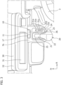
- Figure 5(a) is a sectional view taken along line A-A in Figure 1 .
- Figure 5(b) is an enlarged view of Figure 5(a) .
- the brake switch 11 is disposed below the vehicle-mounted device 30.
- the brake switch 11 is a switch having a mechanical structure, and includes a switch main body 12, and a switch case 13 that stores the switch main body 12 in which an opening is formed and which stores the switch main body 12. Note that the switch case 13 also stores the operation switch 17.
- the switch case 13 is disposed so as to protrude from the surface of the upward inclination 7b (see Figure 4 ).
- An upper side of the switch case 13 includes a convex curve 14 formed to have a gradually curved shape that is convex toward the cabin 100 from the surface of the upward inclination 7b.
- the switch main body 12 includes a design wall 12a that faces the inside of the cabin 100, and an upper wall 12b that stands from the upper end of the design wall 12a toward the outside of the cabin 100.
- the upper end of the design wall 12a is provided with a protrusion 12c serving as an operation end.
- the design wall 12a is formed to have a gradually curved shape that is convex from the upper end toward the lower end so as to be along the convex curve 14 that is convex and has a gradually curved shape.
- the switch main body 12 On the lower end side of the switch main body 12, a turning shaft 12d that extends in the vehicle width direction is provided.
- the turning shaft 12d is supported by the switch case 13.
- the switch main body 12 is turnable around the turning shaft 12d.
- the protrusion 12c is swung around the turning shaft 12d between the inside of the cabin 100 and the outside of the cabin 100 (rear and front: right and left in Figure 5 ).
- the brake switch 11 includes a limit switch, not shown. The limit switch is turned on and off by the operation of the brake switch 11, thus switching the braking state or the brake unlocked state of the parking brake.
- the switch case 13 includes a guide 15 that is formed concave from the surface of the switch case 13 above the upper wall 12b of the switch main body 12.
- the guide 15 includes: a vertical wall 15a that has an upper end connected to the surface of the switch case 13, and extends in the vertical direction from the surface of the switch case 13 toward the outside of the cabin (lower side in Figure 5 ); and a concave curve 15b that is connected to the lower end of the vertical wall 15a and is formed to have a concave and gradually curved shape.
- the vertical wall 15a is disposed to face the upper wall 12b.
- a clearance is provided between the lower end of the concave curve 15b and the lower end of the upper wall 12b.
- the guide 15 and the upper wall 12b form a depression 16 formed to be concave from the design surface of the switch case 13.
- the brake switch 11 switches the braking state or the brake unlocked state of the parking brake by pulling up the protrusion 12c serving as the operation end to the inside of the cabin 100.
- the driver switches the shift lever 21 from the D-range 21d to the P-range 21a, and subsequently pulls up the protrusion 12c to the inside of the cabin 100, thus operating the limit switch to switch the parking brake to the braking state.
- the parking brake is switched to the brake unlocked state.
- the guide 15 formed concave above the upper wall 12b of the brake switch 11, and the upper wall 12b constitute the depression 16 formed concave from the design surface of the switch case 13. Accordingly, when the driver operates the brake switch 11, the driver can insert a finger into the depression 16, put the finger on the protrusion 12c, and pull it up to the inside of the cabin 100. Consequently, the operability of the brake switch 11 is improved.
- the depression 16 formed concave from the surface of the switch case 13 in the brake switch 11 is disposed forward of the lower end of the cabin 100 side inner surface of the vehicle-mounted device 30 disposed above the brake switch 11. More specifically, the depression 16 is disposed forward of a corner part formed by the cabin 100 side inner surface and the lower surface of the outer frame 32 of the vehicle-mounted device 30.
- the brake switch 11 is disposed so as to overlap the vehicle-width-direction width of the vehicle-mounted device 30 in the vehicle width direction.
- the operation switch 17 is a press-type button switch, is stored in the switch case 13, and is disposed adjacent to the brake switch 11 on the passenger's seat side. As shown in Figure 4 , the upper end 17a of the operation switch 17 disposed adjacent to the brake switch 11 is disposed below the protrusion 12c disposed at the upper end of the brake switch 11.
- the brake switch 11 is a switch to be operated by pulling the protrusion 12c to the inside of the cabin.
- the operation switch 17 is a press-type button switch.
- the upper end 17a of the operation switch 17 is disposed below the protrusion 12c of the brake switch 11. Accordingly, erroneous operations in a mixing-up manner between the brake switch 11 and the operation switch 17 can be reduced.
- the brake switch 11 is a switch having a mechanical structure.
- a software switch such as a touch panel switch, may be adopted.
- the operation position for stopping the vehicle (P-range) is configured higher than the operation position for driving the vehicle forward (D-range) in the shift lever 21, and the brake switch 11 is disposed above the shift lever 21.
- the vehicle instrument panel structure 50 includes: the instrument panel 2; the shift lever 21 (operation unit) which is disposed on the instrument panel 2 and in which an operation direction for changing a driving condition is configured in a vertical direction; and the brake switch 11 that generates a braking force for a vehicle, and at the shift lever 21, an operation position for stopping the vehicle (P-range) is configured above an operation position for driving the vehicle forward (D-range), and the brake switch 11 is disposed above the shift lever 21.
- the driver can move the shift lever 21 from the D-range to the P-range disposed upward, and then operate the brake switch 11 disposed above the shift lever unit 20. Consequently, transition from the operation of the shift lever 21 to the operation of the brake switch 11 can be achieved by a smooth action.
- the shift lever unit 20 includes the shift lever panel 24 (supporter) in which the longitudinal slit 25 that is formed in the vertical direction and permits the shift lever 21 to be moved in the vertical direction, and in the vehicle width direction, the brake switch 11 is disposed in the vehicle-width-direction width range of the shift lever panel 24.
- the transition from the operation of the shift lever 21 to the operation of the brake switch 11 can be further achieved by a smooth action.
- the shift lever panel 24 (supporter) and the brake switch 11 are disposed closer to the passenger's seat than the steering wheel 3 disposed on the instrument panel 2 closer to the driver's seat, and in the vertical direction, the brake switch 11 is disposed in the vertical-direction width range of the steering wheel 3.
- the brake switch 11 in the vertical direction, is disposed in the vertical-direction width range of the steering wheel 3. Consequently, the transition from the operation of the shift lever 21 to the operation of the brake switch 11 can be further achieved by a smooth action.
- the unlock button 23 that allows the shift lever 21 to be operated is provided on the vehicle-width-direction driver's-seat-side end face of the grip 22 provided at the distal end of the shift lever 21 (operation unit).
- the brake switch 11 is disposed so as to include the vehicle-width-direction driver's-seat-side end face of the grip 22.
- the index finger is arranged on the passenger's seat side of the grip driver's-seat-side end face 26.
- the index finger can be smoothly guided to the brake switch 11.
- the instrument panel 2 includes the upward inclination 7b inclined rearward as it goes from upward to downward, and the brake switch 11 is disposed on at the upward inclination 7b.
- the transition from the operation of the shift lever 21 to the operation of the brake switch 11 can be further achieved by a smooth action.
- the vehicle instrument panel structure 50 includes: the instrument panel 2; the shift lever 21 (operation unit) which is disposed on the instrument panel 2 and in which an operation direction for changing a driving condition is configured in a vertical direction; and the brake switch 11 that generates a braking force for a vehicle, in which at the shift lever 21, an operation position for stopping the vehicle (P-range) is configured above an operation position for driving the vehicle forward (D-range), and the brake switch 11 is disposed above the shift lever 21.
- the shift lever 21 operation unit
- the brake switch 11 that generates a braking force for a vehicle, in which at the shift lever 21, an operation position for stopping the vehicle (P-range) is configured above an operation position for driving the vehicle forward (D-range), and the brake switch 11 is disposed above the shift lever 21.
- an aspect may be adopted that is a vehicle instrument panel structure 50 that includes: the instrument panel 2; the shift lever 21 (operation unit) which is disposed on the instrument panel 2 and in which an operation direction for changing a driving condition is configured in a vertical direction; and the brake switch 11 that generates a braking force for a vehicle, in which at the shift lever 21, an operation position for stopping the vehicle is configured below an operation position for driving the vehicle forward, and the brake switch 11 is disposed below the shift lever 21.
- a vehicle instrument panel structure 50 that includes: an instrument panel 2; a shift lever 21 (operation unit) which is disposed on the instrument panel 2 and in which an operation direction for changing a driving condition is configured in a vertical direction; and a brake switch 11 that generates a braking force for a vehicle, wherein at the shift lever 21, an operation position for stopping the vehicle is configured below an operation position for driving the vehicle forward, the structure 50 further includes a shift lever panel (supporter) 24 in which a longitudinal slit 25 for permitting the shift lever 21 to move in the vertical direction is formed, in a vehicle width direction, the brake switch 11 is disposed in a vehicle-width-direction width range of the shift lever panel 24, and the brake switch 11 is disposed below the shift lever 21.
- the vehicle instrument panel structure 50 may include: the instrument panel 2; the shift lever 21 (operation unit) which is disposed on the instrument panel 2 and in which an operation direction for changing a driving condition is configured in a vertical direction; and the brake switch 11 that generates a braking force for a vehicle, and at the shift lever 21, the operation position for stopping the vehicle (P-range) and the operation position for driving the vehicle forward (D-range) may be disposed in the vertical direction, and the brake switch 11 is disposed closer to the operation position for stopping the vehicle than the operation position for driving the vehicle forward in the vertical direction.
- the vehicle instrument panel structure 50 that includes the instrument panel 2, and the shift lever 21 (operation unit) which is disposed on the instrument panel 2 and in which the operation direction for changing the driving condition is configured in the vertical direction is described.
- the operation position for stopping the vehicle (P-range) and the operation position for driving the vehicle forward (D-range) may be disposed in the front-rear direction
- the brake switch 11 may be disposed closer in the front-rear direction to the operation position for stopping the vehicle than the operation position for driving the vehicle forward.
Landscapes
- Engineering & Computer Science (AREA)
- Chemical & Material Sciences (AREA)
- Combustion & Propulsion (AREA)
- Transportation (AREA)
- Mechanical Engineering (AREA)
- Arrangement Or Mounting Of Control Devices For Change-Speed Gearing (AREA)
- Instrument Panels (AREA)
Abstract
[Problem to be Solved] A vehicle instrument panel structure is provided that allows transition from an operation of a shift lever to an operation of an EPB switch to be smoothly performed.
[Solution] A vehicle instrument panel structure includes: an instrument panel 2; an shift lever 21 which is disposed on the instrument panel 2 and in which an operation direction for changing a driving condition is configured in a vertical direction; and a brake switch 11 that generates a braking force for a vehicle, and at the shift lever 21, an operation position for stopping the vehicle is configured above an operation position for driving the vehicle forward, and the brake switch 11 is disposed above the shift lever 21.
Description
- The present invention relates to a vehicle instrument panel structure in which an operation switch for operating an electric parking brake, and a shift lever, are arranged on an instrument panel.
-
Patent Literature 1 describes an operation switch for operating an electric parking brake. The operation switch (hereinafter called an EPB switch) described inPatent Literature 1 is disposed rearward of a shift lever provided at the center in the vehicle width direction of an electric vehicle. The shift lever described inPatent Literature 1 includes a drive range (D-range), a regeneration range (B-range; also called a brake range), a reverse range (R-range), a neutral range (N-range), and a parking range (P-range), as shift ranges. The shift ranges are linearly disposed from the front side of the electric vehicle in the order the P-range, the R-range, the B-range, the N-range, and the D-range. -
Patent Literature 2 describes a vehicle instrument panel structure that includes a switch operation unit, and a shift lever on an instrument panel. The shift lever attached to the instrument panel described inPatent Literature 2 is disposed at the center of the instrument panel in the vehicle width direction, and the switch operation unit is disposed on a passenger's seat side, i.e., on the left side of the shift lever. The operation direction of the shift lever is the vertical direction along the surface of the instrument panel. - Typically, actions in a case of operating an EPB switch are a series of actions that move the shift lever forward or upward from the D-range into the P-range for parking, and subsequently operating the EPB switch.
-
- [Patent Literature 1]
JP 2016-107769 A - [Patent Literature 2]
JP 2021-062661 A - Unfortunately, the EPB switch described in
Patent Literature 1 is disposed rearward of the shift lever. Accordingly, after a driver moves the shift lever forward into the P-range, the driver has to move an operating arm rearward in order to operate the EPB switch. Thus, transition from the operation of the shift lever to the operation of the EPB switch cannot be smoothly performed. This similarly applies to the case of the shift lever attached to the instrument panel described inPatent Literature 2. - Accordingly, the present invention has as an object to provide a vehicle instrument panel structure that allows transition from an operation of a shift lever to an operation of an EPB switch to be smoothly performed.
- An aspect of the present invention is a vehicle instrument panel structure that includes: an instrument panel; an operation unit which is disposed on the instrument panel and in which an operation direction for changing a driving condition is configured in a vertical direction; and a brake switch that generates a braking force for a vehicle, and at the operation unit, an operation position for stopping the vehicle is configured above an operation position for driving the vehicle forward, and the brake switch is disposed above the operation unit.
- According to the present invention, a vehicle instrument panel can be provided that allows transition from an operation of a shift lever to an operation of an EPB switch to be smoothly performed.
-
- [
Figure 1] Figure 1 is a perspective view of a vehicle instrument panel structure that includes a shift lever and a brake switch according to the present embodiment. - [
Figure 2] Figure 2 is a front view of the vehicle instrument panel structure that includes the shift lever and the brake switch according to the present embodiment. - [
Figure 3] Figure 3 is an enlarged plan view of the vehicle instrument panel structure that includes the shift lever and the brake switch according to the present embodiment. - [
Figure 4] Figure 4 is an enlarged perspective view of the vehicle instrument panel structure that includes the shift lever and the brake switch according to the present embodiment. - [
Figure 5] Figure 5(a) is a sectional view taken along line A-A inFigure 1 ; andFigure 5(b) is an enlarged view of (a). - Hereinafter, a vehicle
instrument panel structure 50 according to the present invention is described based on the accompanying drawings. Note that in the diagrams, an arrow Fr direction indicates the forward direction in the vehicle front-rear direction. An arrow R indicates the right when an occupant looks vehicle-frontward. An arrow U indicates a vehicle upward direction. -
Figure 1 is a perspective view of the vehicleinstrument panel structure 50 according to the present embodiment.Figure 2 is a front view of the vehicleinstrument panel structure 50 according to the present embodiment. Note that the present embodiment indicates a so-called right-hand-drive embodiment in which the driver's seat is disposed on the right side of acabin 100 when facing forward of the vehicle, and the passenger's seat is disposed on the left side of thecabin 100. In a so-called left-hand-drive case in which the driver's seat is disposed on the left side of acabin 100 when facing forward of the vehicle, the embodiment is bilaterally symmetrical to the embodiment shown inFigure 1 .Figure 3 is an enlarged plan view of the vehicleinstrument panel structure 50 according to the present embodiment.Figure 4 is an enlarged perspective view of the vehicleinstrument panel structure 50 according to the present embodiment. - Referring to
Figures 1 to 4 , the vehicleinstrument panel structure 50 according to the present embodiment is described. As shown inFigure 1 , the vehicleinstrument panel structure 50 according to the present embodiment includes aninstrument panel 2 that extends in the vehicle width direction below afront windshield 1, at a front part of thecabin 100. Asteering wheel 3 is attached to a portion of theinstrument panel 2 on the driver's seat side (a portion on the right side inFigure 1 ) via a column shaft covered with a column cover. In order from the top, a vehicle-mounteddevice 30, aswitch unit 10, and ashift lever unit 20, which are described later, are attached to a portion at the center portion of theinstrument panel 2. That is, the vehicle-mounteddevice 30, theswitch unit 10, and theshift lever unit 20 are disposed on theinstrument panel 2 closer to the passenger's seat than thesteering wheel 3 in the vehicle width direction. - The
instrument panel 2 includes anupper member 4 and alower member 5 that are disposed vertically. Theupper member 4 includes atop surface 6 and arear surface 7. Thetop surface 6 faces upward, and extends in the vehicle width direction so as to connect the opposite sides of thecabin 100. On the front side of thetop surface 6, thefront windshield 1 is disposed. Therear surface 7 is disposed between thetop surface 6 and thelower member 5, and extends in the vehicle width direction so as to connect the opposite sides of thecabin 100. Therear surface 7 includes: avertical surface 7a that has an upper end connected to the rear end of thetop surface 6, and faces rearward; and anupward inclination 7b that has an upper end connected to a lower end of thevertical surface 7a, and a lower end connected to an upper end of thelower member 5. As shown inFigure 4 , theupward inclination 7b is formed to be inclined rearward as it goes downward from the upper end of theupward inclination 7b, i.e., be inclined upward. The position of theupward inclination 7b in the vertical direction is disposed substantially the same as the center position of thesteering wheel 3. - Next, referring to
Figures 2 to 4 , theshift lever unit 20 is described. As shown inFigure 2 , theshift lever unit 20 is disposed such that the center of theshift lever unit 20 in the vertical direction can overlap the lower end of the steering wheel, at the center of theinstrument panel 2 in the vehicle width direction. Theshift lever unit 20 is a unit for shifting gears of a transmission disposed between an engine of the vehicle and wheels, which are not shown, protrudes from theinstrument panel 2 into the cabin, and includes ashift lever 21 having an operation direction in the vertical direction along the surface of theinstrument panel 2, agrip 22 provided at the distal end of theshift lever 21, and ashift lever panel 24 fixed to the design surface of theinstrument panel 2. A vertical-directionlongitudinal slit 25 that permits theshift lever 21 to move in the vertical direction is formed in theshift lever panel 24. Note that theshift lever 21 is an operation unit in the present invention, and theshift lever panel 24 is a supporter in the present invention. - As shown in
Figure 3 , theshift lever unit 20 in the present embodiment includes, as shift ranges: a P-range 21a serving as an operation position for stopping the vehicle; an R-range 21b serving as an operation position for driving the vehicle rearward; an N-range 21c in a state of providing no drive force to the wheels; a D-range 21d serving as an operation position for driving the vehicle forward; and a low range (L-range) 21e that is for driving the vehicle forward and is for a low speed. Among the shift ranges, the P-range 21a is disposed uppermost on theshift lever panel 24, and then the R-range 21b, the N-range 21c, the D-range 21d, and the L-range 21e are disposed downward, in this order. That is, the P-range 21a is disposed higher than the D-range 21d. For example, the operation of theshift lever 21 is such that the shift range is set in the D-range 21d during traveling, and is set in the P-range 21a to make the vehicle stop in the state for parking. Accordingly, for parking, a driver performs an action of moving theshift lever 21 from the D-range 21d toward the P-range above the D-range 21d, i.e., an operation of moving theshift lever 21 upward. - A grip driver's-seat-
side end face 26 that is an end face of thegrip 22 on the driver's seat side in the vehicle width direction is provided with anunlock button 23 that protrudes from the grip driver's-seat-side end face 26. Theunlock button 23 is a button used when theshift lever 21 is operated, by pressing thisunlock button 23. In the case of operating theshift lever 21, even if an attempt is made to move theshift lever 21 upward for transition from the state of the D-range 21d to the P-range 21a, it cannot be moved because theshift lever 21 is locked unless theunlock button 23 pressed. Accordingly, to allow the driver to move theshift lever 21 from the state of the D-range 21d to that of the P-range 21a, theshift lever 21 is only allowed to be moved from the state of the D-range 21d to the P-range 21a by pressing theunlock button 23. - Next, referring to
Figures 1 to 4 , theswitch unit 10 according to the present embodiment is described. As shown inFigure 2 , theswitch unit 10 is disposed at theupward inclination 7b of theinstrument panel 2 in the vehicle-width-direction center, and the width of theswitch unit 10 in the vertical direction is disposed within the width of the upper and lower ends of thesteering wheel 3 in the vertical direction. As shown inFigures 3 and4 , theswitch unit 10 includes abrake switch 11, and anoperation switch 17. Thebrake switch 11 is disposed on the driver's seat side, and theoperation switch 17 is disposed adjacent to thebrake switch 11 on the passenger's seat side. Thebrake switch 11 is a switch for generating a braking force for the vehicle, and is, in the present embodiment, a switch for switching between a braking state and a brake unlocked state of a parking brake in a parking brake mechanism, not shown, and is a switch used in a case of parking. Theoperation switch 17 is a switch for holding a state in which a typical foot brake is in operation and, for example, holds the state in which the foot brake is in operation by turning on theoperation switch 17 in a state of waiting for a traffic light, even when the driver takes the foot off the foot brake. Note that in the present embodiment, thebrake switch 11 is a switch for switching between the braking state and the brake unlocked state of the parking brake in the parking brake mechanism. However, there is no necessary limitation to this. Thebrake switch 11 may be at least a switch that can hold the braking state of the parking brake in the parking brake mechanism. - The
brake switch 11 is disposed so as to be above theshift lever unit 20 and within the width of the upper and lower ends of the steering wheel. That is, thebrake switch 11 is disposed so as to be in the width of thesteering wheel 3 in the vertical-direction width, i.e., a range indicated by two upper and lower broken lines extending in the vehicle width direction shown inFigure 2 . - The
brake switch 11 is disposed so as to be within the width range of theshift lever panel 24 in the vehicle width direction, i.e., a range indicated by two left and right broken lines extending in the vertical direction shown inFigure 2 , in the vehicle width direction. That is, thebrake switch 11 is included in the vehicle-width-direction width of theshift lever panel 24 in the vehicle width direction. More specifically, the vertical-direction extended line of the grip driver's-seat-side end face 26 provided with theunlock button 23 in a protruding manner substantially matches the vehicle-width-direction center of thebrake switch 11 in the vehicle width direction. Note that in the present embodiment, the extended line of the grip driver's-seat-side end face 26 in the vertical direction substantially matches the vehicle-width-direction center of thebrake switch 11 in the vehicle width direction. However, there is no necessary limitation to this. In the vehicle width direction, arrangement may be made so that the vehicle-width-direction width of thebrake switch 11 can include the vertical-direction extended line of the grip driver's-seat-side end face 26. - Next, referring to
Figures 1 to 4 , the vehicle-mounteddevice 30 according to the present embodiment is described. The vehicle-mounteddevice 30 is disposed at a center portion of therear surface 7 of theinstrument panel 2. That is, the vehicle-mounteddevice 30 is disposed on theinstrument panel 2 closer to the passenger's seat than thesteering wheel 3 in the vehicle width direction. Theswitch unit 10 is disposed below the vehicle-mounteddevice 30. In the vehicle width direction, theswitch unit 10 is disposed so as to be included in the vehicle-width-direction width range of the vehicle-mounteddevice 30. Consequently, in the vehicle width direction, thebrake switch 11 of theswitch unit 10 is disposed so as to be included in the vehicle-width-direction width of the vehicle-mounteddevice 30. The vehicle-mounteddevice 30 is a display device that includes adisplay unit 31 that is a display, and anouter frame 32 that holds the outer periphery of thedisplay unit 31. Thedisplay unit 31 has a substantially rectangular shape, and theouter frame 32, which holds thedisplay unit 31, also has a substantially rectangular shape. In the present embodiment, the vehicle-mounteddevice 30 is a navigation device that supports driving by the driver. In the present embodiment, the vehicle-mounteddevice 30 is a navigation device. However, without limitation to this, the vehicle-mounteddevice 30 may be an audio device, or an indicator device that indicates the speed or the number of revolutions. - Next, referring to
Figures 4 ,5(a), and 5(b) , the specific structure of thebrake switch 11 is described.Figure 5(a) is a sectional view taken along line A-A inFigure 1 .Figure 5(b) is an enlarged view ofFigure 5(a) . Thebrake switch 11 is disposed below the vehicle-mounteddevice 30. Thebrake switch 11 is a switch having a mechanical structure, and includes a switchmain body 12, and aswitch case 13 that stores the switchmain body 12 in which an opening is formed and which stores the switchmain body 12. Note that theswitch case 13 also stores theoperation switch 17. Theswitch case 13 is disposed so as to protrude from the surface of theupward inclination 7b (seeFigure 4 ). An upper side of theswitch case 13 includes aconvex curve 14 formed to have a gradually curved shape that is convex toward thecabin 100 from the surface of theupward inclination 7b. The switchmain body 12 includes adesign wall 12a that faces the inside of thecabin 100, and anupper wall 12b that stands from the upper end of thedesign wall 12a toward the outside of thecabin 100. The upper end of thedesign wall 12a is provided with aprotrusion 12c serving as an operation end. Thedesign wall 12a is formed to have a gradually curved shape that is convex from the upper end toward the lower end so as to be along theconvex curve 14 that is convex and has a gradually curved shape. On the lower end side of the switchmain body 12, a turningshaft 12d that extends in the vehicle width direction is provided. The turningshaft 12d is supported by theswitch case 13. The switchmain body 12 is turnable around the turningshaft 12d. Theprotrusion 12c is swung around the turningshaft 12d between the inside of thecabin 100 and the outside of the cabin 100 (rear and front: right and left inFigure 5 ). Thebrake switch 11 includes a limit switch, not shown. The limit switch is turned on and off by the operation of thebrake switch 11, thus switching the braking state or the brake unlocked state of the parking brake. - The
switch case 13 includes aguide 15 that is formed concave from the surface of theswitch case 13 above theupper wall 12b of the switchmain body 12. Theguide 15 includes: avertical wall 15a that has an upper end connected to the surface of theswitch case 13, and extends in the vertical direction from the surface of theswitch case 13 toward the outside of the cabin (lower side inFigure 5 ); and aconcave curve 15b that is connected to the lower end of thevertical wall 15a and is formed to have a concave and gradually curved shape. Thevertical wall 15a is disposed to face theupper wall 12b. A clearance is provided between the lower end of theconcave curve 15b and the lower end of theupper wall 12b. Theguide 15 and theupper wall 12b form adepression 16 formed to be concave from the design surface of theswitch case 13. - Since the
switch unit 10 is disposed at theupward inclination 7b that is inclined rearward as it goes from upward to downward, thebrake switch 11 switches the braking state or the brake unlocked state of the parking brake by pulling up theprotrusion 12c serving as the operation end to the inside of thecabin 100. The driver switches theshift lever 21 from the D-range 21d to the P-range 21a, and subsequently pulls up theprotrusion 12c to the inside of thecabin 100, thus operating the limit switch to switch the parking brake to the braking state. By the driver pulling up theprotrusion 12c to the inside of thecabin 100 in the braking state of the parking brake, the parking brake is switched to the brake unlocked state. - The
guide 15 formed concave above theupper wall 12b of thebrake switch 11, and theupper wall 12b constitute thedepression 16 formed concave from the design surface of theswitch case 13. Accordingly, when the driver operates thebrake switch 11, the driver can insert a finger into thedepression 16, put the finger on theprotrusion 12c, and pull it up to the inside of thecabin 100. Consequently, the operability of thebrake switch 11 is improved. - As shown in
Figure 5(b) , thedepression 16 formed concave from the surface of theswitch case 13 in thebrake switch 11 is disposed forward of the lower end of thecabin 100 side inner surface of the vehicle-mounteddevice 30 disposed above thebrake switch 11. More specifically, thedepression 16 is disposed forward of a corner part formed by thecabin 100 side inner surface and the lower surface of theouter frame 32 of the vehicle-mounteddevice 30. Thebrake switch 11 is disposed so as to overlap the vehicle-width-direction width of the vehicle-mounteddevice 30 in the vehicle width direction. Such a configuration achieves arrangement according to which if dust on thedisplay unit 31 of the vehicle-mounteddevice 30, and goods on the vehicle-mounteddevice 30 fall, they do not enter thedepression 16. Consequently, entrance of falling objects into thedepression 16 can be reduced. - The
operation switch 17 is a press-type button switch, is stored in theswitch case 13, and is disposed adjacent to thebrake switch 11 on the passenger's seat side. As shown inFigure 4 , theupper end 17a of theoperation switch 17 disposed adjacent to thebrake switch 11 is disposed below theprotrusion 12c disposed at the upper end of thebrake switch 11. Thebrake switch 11 is a switch to be operated by pulling theprotrusion 12c to the inside of the cabin. Theoperation switch 17 is a press-type button switch. Theupper end 17a of theoperation switch 17 is disposed below theprotrusion 12c of thebrake switch 11. Accordingly, erroneous operations in a mixing-up manner between thebrake switch 11 and theoperation switch 17 can be reduced. - In the present embodiment, the
brake switch 11 is a switch having a mechanical structure. However, there is no necessary limitation to this. Instead of thebrake switch 11 that is a switch having a mechanical structure, for example, a software switch, such as a touch panel switch, may be adopted. Even in the case in which thebrake switch 11 is a software switch, the operation position for stopping the vehicle (P-range) is configured higher than the operation position for driving the vehicle forward (D-range) in theshift lever 21, and thebrake switch 11 is disposed above theshift lever 21. - According to the present embodiment, the vehicle
instrument panel structure 50 includes: theinstrument panel 2; the shift lever 21 (operation unit) which is disposed on theinstrument panel 2 and in which an operation direction for changing a driving condition is configured in a vertical direction; and thebrake switch 11 that generates a braking force for a vehicle, and at theshift lever 21, an operation position for stopping the vehicle (P-range) is configured above an operation position for driving the vehicle forward (D-range), and thebrake switch 11 is disposed above theshift lever 21. - According to this configuration, the driver can move the
shift lever 21 from the D-range to the P-range disposed upward, and then operate thebrake switch 11 disposed above theshift lever unit 20. Consequently, transition from the operation of theshift lever 21 to the operation of thebrake switch 11 can be achieved by a smooth action. - In the present embodiment, the
shift lever unit 20 includes the shift lever panel 24 (supporter) in which thelongitudinal slit 25 that is formed in the vertical direction and permits theshift lever 21 to be moved in the vertical direction, and in the vehicle width direction, thebrake switch 11 is disposed in the vehicle-width-direction width range of theshift lever panel 24. - According to this configuration, the transition from the operation of the
shift lever 21 to the operation of thebrake switch 11 can be further achieved by a smooth action. - In the present embodiment, the shift lever panel 24 (supporter) and the
brake switch 11 are disposed closer to the passenger's seat than thesteering wheel 3 disposed on theinstrument panel 2 closer to the driver's seat, and in the vertical direction, thebrake switch 11 is disposed in the vertical-direction width range of thesteering wheel 3. - According to this configuration, in the vertical direction, the
brake switch 11 is disposed in the vertical-direction width range of thesteering wheel 3. Consequently, the transition from the operation of theshift lever 21 to the operation of thebrake switch 11 can be further achieved by a smooth action. - In the present embodiment, on the vehicle-width-direction driver's-seat-side end face of the
grip 22 provided at the distal end of the shift lever 21 (operation unit), theunlock button 23 that allows theshift lever 21 to be operated is provided. In the vehicle width direction, thebrake switch 11 is disposed so as to include the vehicle-width-direction driver's-seat-side end face of thegrip 22. - According to this configuration, since the
unlock button 23 is typically operated by the driver with a thumb, the index finger is arranged on the passenger's seat side of the grip driver's-seat-side end face 26. Thus, the index finger can be smoothly guided to thebrake switch 11. - In the present embodiment, the
instrument panel 2 includes theupward inclination 7b inclined rearward as it goes from upward to downward, and thebrake switch 11 is disposed on at theupward inclination 7b. - According to this configuration, the transition from the operation of the
shift lever 21 to the operation of thebrake switch 11 can be further achieved by a smooth action. - According to the embodiment described above, the vehicle
instrument panel structure 50 includes: theinstrument panel 2; the shift lever 21 (operation unit) which is disposed on theinstrument panel 2 and in which an operation direction for changing a driving condition is configured in a vertical direction; and thebrake switch 11 that generates a braking force for a vehicle, in which at theshift lever 21, an operation position for stopping the vehicle (P-range) is configured above an operation position for driving the vehicle forward (D-range), and thebrake switch 11 is disposed above theshift lever 21. However, there is no necessary limitation to this. For example, an aspect may be adopted that is a vehicleinstrument panel structure 50 that includes: theinstrument panel 2; the shift lever 21 (operation unit) which is disposed on theinstrument panel 2 and in which an operation direction for changing a driving condition is configured in a vertical direction; and thebrake switch 11 that generates a braking force for a vehicle, in which at theshift lever 21, an operation position for stopping the vehicle is configured below an operation position for driving the vehicle forward, and thebrake switch 11 is disposed below theshift lever 21. - Alternatively, an aspect may be adopted in which a vehicle
instrument panel structure 50 that includes: aninstrument panel 2; a shift lever 21 (operation unit) which is disposed on theinstrument panel 2 and in which an operation direction for changing a driving condition is configured in a vertical direction; and abrake switch 11 that generates a braking force for a vehicle, wherein at theshift lever 21, an operation position for stopping the vehicle is configured below an operation position for driving the vehicle forward, thestructure 50 further includes a shift lever panel (supporter) 24 in which alongitudinal slit 25 for permitting theshift lever 21 to move in the vertical direction is formed, in a vehicle width direction, thebrake switch 11 is disposed in a vehicle-width-direction width range of theshift lever panel 24, and thebrake switch 11 is disposed below theshift lever 21. - Alternatively, the vehicle
instrument panel structure 50 may include: theinstrument panel 2; the shift lever 21 (operation unit) which is disposed on theinstrument panel 2 and in which an operation direction for changing a driving condition is configured in a vertical direction; and thebrake switch 11 that generates a braking force for a vehicle, and at theshift lever 21, the operation position for stopping the vehicle (P-range) and the operation position for driving the vehicle forward (D-range) may be disposed in the vertical direction, and thebrake switch 11 is disposed closer to the operation position for stopping the vehicle than the operation position for driving the vehicle forward in the vertical direction. - In the present embodiment, the vehicle
instrument panel structure 50 that includes theinstrument panel 2, and the shift lever 21 (operation unit) which is disposed on theinstrument panel 2 and in which the operation direction for changing the driving condition is configured in the vertical direction is described. However, there is no necessary limitation to this. For example, in a shift lever which is provided at a center console between the driver's seat and the passenger's seat and in which the operation method is in the front-rear direction, the operation position for stopping the vehicle (P-range) and the operation position for driving the vehicle forward (D-range) may be disposed in the front-rear direction, and in the front-rear direction, thebrake switch 11 may be disposed closer in the front-rear direction to the operation position for stopping the vehicle than the operation position for driving the vehicle forward. - The embodiment of the present invention and its modification example have thus been described above. However, the present invention is not limited to the embodiment and modification example described above. Further modifications and changes can be made based on the technical concept of the present invention.
-
- 1
- Front windshield
- 2
- Instrument panel
- 3
- Steering wheel
- 4
- Upper member
- 5
- Lower member
- 6
- Top surface
- 7
- Rear surface
- 7a
- Vertical surface
- 7b
- Upward inclination
- 10
- Switch unit
- 11
- Brake switch
- 12
- Switch main body
- 12a
- Design wall
- 12b
- Upper wall
- 12c
- Protrusion
- 12d
- Turning shaft
- 13
- Switch case
- 14
- Convex curve
- 15
- Guide
- 15a
- Vertical wall
- 15b
- Concave curve
- 16
- Depression
- 17
- Operation switch
- 17a
- Upper end
- 20
- Shift lever unit
- 21
- Shift lever (operation unit)
- 21a
- P-range
- 21b
- R-range
- 21c
- N-range
- 21d
- D-range
- 21e
- L-range
- 22
- Grip
- 23
- Unlock button
- 24
- Shift lever panel (supporter)
- 25
- Slit
- 26
- Grip driver's-seat-side end face
- 30
- Vehicle-mounted device
- 31
- Display unit
- 32
- Outer frame
- 50
- Vehicle instrument panel structure
- 100
- Cabin
Claims (9)
- A vehicle instrument panel structure comprising:an instrument panel;an operation unit which is disposed on the instrument panel and in which an operation direction for changing a driving condition is configured in a vertical direction; anda brake switch that generates a braking force for a vehicle, characterized in thatat the operation unit, an operation position for stopping the vehicle is configured above an operation position for driving the vehicle forward, andthe brake switch is disposed above the operation unit.
- The vehicle instrument panel structure according to claim 1, whereinthe structure further comprises a supporter in which a longitudinal slit for permitting the operation unit to move in the vertical direction is formed, andin a vehicle width direction, the brake switch is disposed in a vehicle-width-direction width range of the supporter.
- The vehicle instrument panel structure according to claim 2, whereinin the vehicle width direction, the supporter and the brake switch are disposed closer to a passenger's seat than a steering wheel disposed closer to a driver's seat on the instrument panel, andin the vertical direction, the brake switch is disposed in a vertical-direction width range of the steering wheel.
- The vehicle instrument panel structure according to claim 2, whereinon a vehicle-width-direction driver's-seat-side end face of a grip provided at a distal end of the operation unit, an unlock button that allows the operation unit to be operated is provided, andin the vehicle width direction, the brake switch is disposed so as to include the vehicle-width-direction driver's-seat-side end face of the grip.
- The vehicle instrument panel structure according to claim 3, whereinthe instrument panel includes an upward inclination that has a design surface inclined rearward as going from upward to downward, andthe brake switch is disposed on the upward inclination.
- The vehicle instrument panel structure according to claim 5, wherein
the brake switch includes:a switch main body that includes a protrusion disposed at an upper end, and is turnable around a shaft that is positioned on a lower end side and extends in the vehicle width direction; anda switch case that is installed on the upward inclination, and stores the switch main body,the switch main body includes a design wall formed so as to be along a surface of the switch case, and an upper wall disposed to stand outward in a cabin from an upper end of the design wall,the switch case includes a guide formed concave from the surface of the switch case above the switch main body, and the guide includes a concave curve that has a concave shape,the guide and the upper wall constitute a depression, andthe brake switch holds a parking brake in a braking state by pulling up the protrusion to an inside of the cabin. - The vehicle instrument panel structure according to claim 6, whereina vehicle-mounted device is provided at an upper part of the instrument panel,the brake switch is disposed below the vehicle-mounted device, and the brake switch is disposed so as to overlap the vehicle-mounted device in the vehicle width direction, andthe depression is disposed forward of a lower end of a cabin side inner surface of the vehicle-mounted device.
- The vehicle instrument panel structure according to claim 6, whereinan operation switch is disposed adjacent to the brake switch on a passenger's seat side, the operation switch is a press-type button switch, andan upper end of the operation switch is disposed lower than an upper end of the brake switch.
- A vehicle instrument panel structure comprising:an instrument panel;an operation unit which is disposed on the instrument panel and in which an operation direction for changing a driving condition is configured in a vertical direction; anda brake switch that generates a braking force for a vehicle, characterized in thatat the operation unit, an operation position for stopping the vehicle is configured below an operation position for driving the vehicle forward,the vehicle instrument panel structure further comprises a supporter in which a longitudinal slit for permitting the operation unit to move in the vertical direction is formed,in a vehicle width direction, the brake switch is disposed in a vehicle-width-direction width range of the supporter, andthe brake switch is disposed below the operation unit.
Applications Claiming Priority (1)
| Application Number | Priority Date | Filing Date | Title |
|---|---|---|---|
| JP2023131983A JP2025027299A (en) | 2023-08-14 | 2023-08-14 | Vehicle instrument panel structure |
Publications (1)
| Publication Number | Publication Date |
|---|---|
| EP4512649A1 true EP4512649A1 (en) | 2025-02-26 |
Family
ID=91954082
Family Applications (1)
| Application Number | Title | Priority Date | Filing Date |
|---|---|---|---|
| EP24188931.0A Pending EP4512649A1 (en) | 2023-08-14 | 2024-07-16 | Vehicle instrument panel structure |
Country Status (2)
| Country | Link |
|---|---|
| EP (1) | EP4512649A1 (en) |
| JP (1) | JP2025027299A (en) |
Citations (5)
| Publication number | Priority date | Publication date | Assignee | Title |
|---|---|---|---|---|
| US20100056331A1 (en) * | 2007-03-26 | 2010-03-04 | Volvo Lastvagnar Ab | control device for operating a gear box of a vehicle, a system for gear shift and parking brake actuation and a vehicle comprising a control device and a system |
| JP2016107769A (en) | 2014-12-04 | 2016-06-20 | 三菱自動車工業株式会社 | Electric parking brake device |
| US20180086322A1 (en) * | 2016-09-24 | 2018-03-29 | Bendix Commercial Vehicle Systems Llc | Electronic park brake interface module, park brake controller and system |
| JP2021062661A (en) | 2019-10-10 | 2021-04-22 | スズキ株式会社 | Vehicle interior structure |
| EP4006688A1 (en) * | 2019-09-10 | 2022-06-01 | Komatsu Ltd. | Operation device and work vehicle |
-
2023
- 2023-08-14 JP JP2023131983A patent/JP2025027299A/en active Pending
-
2024
- 2024-07-16 EP EP24188931.0A patent/EP4512649A1/en active Pending
Patent Citations (5)
| Publication number | Priority date | Publication date | Assignee | Title |
|---|---|---|---|---|
| US20100056331A1 (en) * | 2007-03-26 | 2010-03-04 | Volvo Lastvagnar Ab | control device for operating a gear box of a vehicle, a system for gear shift and parking brake actuation and a vehicle comprising a control device and a system |
| JP2016107769A (en) | 2014-12-04 | 2016-06-20 | 三菱自動車工業株式会社 | Electric parking brake device |
| US20180086322A1 (en) * | 2016-09-24 | 2018-03-29 | Bendix Commercial Vehicle Systems Llc | Electronic park brake interface module, park brake controller and system |
| EP4006688A1 (en) * | 2019-09-10 | 2022-06-01 | Komatsu Ltd. | Operation device and work vehicle |
| JP2021062661A (en) | 2019-10-10 | 2021-04-22 | スズキ株式会社 | Vehicle interior structure |
Also Published As
| Publication number | Publication date |
|---|---|
| JP2025027299A (en) | 2025-02-27 |
Similar Documents
| Publication | Publication Date | Title |
|---|---|---|
| JP4300728B2 (en) | Vehicle speed change operation device | |
| US6621176B1 (en) | Input device for use in vehicles for inputting settings pertaining to driver's intention of acceleration and deceleration | |
| CN103958254A (en) | Method for switching a hybrid drive from one operating mode to another operating mode and hybrid vehicle | |
| EP4029741B1 (en) | Driving assistance apparatus | |
| KR102363488B1 (en) | Operation device for autonomous vehicle | |
| US8387739B2 (en) | Shift device | |
| JP2006160098A (en) | Shifting device for automatic transmission | |
| EP4512649A1 (en) | Vehicle instrument panel structure | |
| KR101382694B1 (en) | Sliding Pop Up type Shift Lever Device | |
| JPH05301533A (en) | Shift lever for vehicle | |
| JP5015614B2 (en) | Vehicle travel system combination switch device | |
| JP5547025B2 (en) | Shift device | |
| JP2008254690A (en) | Vehicle travel system combination switch device | |
| JP2006160012A (en) | Vehicle travel control device | |
| JPH10329567A (en) | Car steering switch | |
| CN113494596A (en) | Shift control system for automatic transmission | |
| JP3643256B2 (en) | Shift lever device for automatic transmission | |
| JP2006273208A (en) | Shift lever device | |
| JPH0554859U (en) | Auto change | |
| JP4808397B2 (en) | forklift | |
| CN113494597A (en) | Shift control system for automatic transmission | |
| JPH07332477A (en) | Gear shifting operation device for automatic transmission | |
| JPH066057U (en) | Gear shift operation device for automobile transmission | |
| JPH0716066U (en) | Electric auto change | |
| KR20250117942A (en) | Vehicle Control System comprising Steering Wheel with Motion Knob |
Legal Events
| Date | Code | Title | Description |
|---|---|---|---|
| PUAI | Public reference made under article 153(3) epc to a published international application that has entered the european phase |
Free format text: ORIGINAL CODE: 0009012 |
|
| STAA | Information on the status of an ep patent application or granted ep patent |
Free format text: STATUS: REQUEST FOR EXAMINATION WAS MADE |
|
| 17P | Request for examination filed |
Effective date: 20240716 |
|
| AK | Designated contracting states |
Kind code of ref document: A1 Designated state(s): AL AT BE BG CH CY CZ DE DK EE ES FI FR GB GR HR HU IE IS IT LI LT LU LV MC ME MK MT NL NO PL PT RO RS SE SI SK SM TR |