EP4006688A1 - Operation device and work vehicle - Google Patents
Operation device and work vehicle Download PDFInfo
- Publication number
- EP4006688A1 EP4006688A1 EP20863043.4A EP20863043A EP4006688A1 EP 4006688 A1 EP4006688 A1 EP 4006688A1 EP 20863043 A EP20863043 A EP 20863043A EP 4006688 A1 EP4006688 A1 EP 4006688A1
- Authority
- EP
- European Patent Office
- Prior art keywords
- switch
- operation device
- shift lever
- hoist
- section
- Prior art date
- Legal status (The legal status is an assumption and is not a legal conclusion. Google has not performed a legal analysis and makes no representation as to the accuracy of the status listed.)
- Pending
Links
- 230000003028 elevating effect Effects 0.000 claims abstract description 23
- 238000000638 solvent extraction Methods 0.000 claims abstract description 15
- 238000005192 partition Methods 0.000 claims abstract description 6
- 230000008859 change Effects 0.000 claims abstract description 5
- 230000007935 neutral effect Effects 0.000 claims description 49
- 210000003811 finger Anatomy 0.000 description 13
- 238000009434 installation Methods 0.000 description 11
- 210000005224 forefinger Anatomy 0.000 description 8
- 230000008901 benefit Effects 0.000 description 3
- 210000004247 hand Anatomy 0.000 description 2
- 230000007257 malfunction Effects 0.000 description 2
- 238000000034 method Methods 0.000 description 2
- 210000003813 thumb Anatomy 0.000 description 2
- 210000001015 abdomen Anatomy 0.000 description 1
- 238000007792 addition Methods 0.000 description 1
- 230000005540 biological transmission Effects 0.000 description 1
- 230000015572 biosynthetic process Effects 0.000 description 1
- 235000019504 cigarettes Nutrition 0.000 description 1
- 230000007423 decrease Effects 0.000 description 1
- 230000003247 decreasing effect Effects 0.000 description 1
- 230000000694 effects Effects 0.000 description 1
- 210000004932 little finger Anatomy 0.000 description 1
- 238000012986 modification Methods 0.000 description 1
- 230000004048 modification Effects 0.000 description 1
- 238000006467 substitution reaction Methods 0.000 description 1
- 230000003867 tiredness Effects 0.000 description 1
- 208000016255 tiredness Diseases 0.000 description 1
Images


Classifications
-
- E—FIXED CONSTRUCTIONS
- E02—HYDRAULIC ENGINEERING; FOUNDATIONS; SOIL SHIFTING
- E02F—DREDGING; SOIL-SHIFTING
- E02F9/00—Component parts of dredgers or soil-shifting machines, not restricted to one of the kinds covered by groups E02F3/00 - E02F7/00
- E02F9/20—Drives; Control devices
- E02F9/2004—Control mechanisms, e.g. control levers
-
- B—PERFORMING OPERATIONS; TRANSPORTING
- B60—VEHICLES IN GENERAL
- B60K—ARRANGEMENT OR MOUNTING OF PROPULSION UNITS OR OF TRANSMISSIONS IN VEHICLES; ARRANGEMENT OR MOUNTING OF PLURAL DIVERSE PRIME-MOVERS IN VEHICLES; AUXILIARY DRIVES FOR VEHICLES; INSTRUMENTATION OR DASHBOARDS FOR VEHICLES; ARRANGEMENTS IN CONNECTION WITH COOLING, AIR INTAKE, GAS EXHAUST OR FUEL SUPPLY OF PROPULSION UNITS IN VEHICLES
- B60K20/00—Arrangement or mounting of change-speed gearing control devices in vehicles
- B60K20/02—Arrangement or mounting of change-speed gearing control devices in vehicles of initiating means
-
- B—PERFORMING OPERATIONS; TRANSPORTING
- B60—VEHICLES IN GENERAL
- B60K—ARRANGEMENT OR MOUNTING OF PROPULSION UNITS OR OF TRANSMISSIONS IN VEHICLES; ARRANGEMENT OR MOUNTING OF PLURAL DIVERSE PRIME-MOVERS IN VEHICLES; AUXILIARY DRIVES FOR VEHICLES; INSTRUMENTATION OR DASHBOARDS FOR VEHICLES; ARRANGEMENTS IN CONNECTION WITH COOLING, AIR INTAKE, GAS EXHAUST OR FUEL SUPPLY OF PROPULSION UNITS IN VEHICLES
- B60K35/00—Instruments specially adapted for vehicles; Arrangement of instruments in or on vehicles
- B60K35/10—Input arrangements, i.e. from user to vehicle, associated with vehicle functions or specially adapted therefor
-
- B—PERFORMING OPERATIONS; TRANSPORTING
- B60—VEHICLES IN GENERAL
- B60K—ARRANGEMENT OR MOUNTING OF PROPULSION UNITS OR OF TRANSMISSIONS IN VEHICLES; ARRANGEMENT OR MOUNTING OF PLURAL DIVERSE PRIME-MOVERS IN VEHICLES; AUXILIARY DRIVES FOR VEHICLES; INSTRUMENTATION OR DASHBOARDS FOR VEHICLES; ARRANGEMENTS IN CONNECTION WITH COOLING, AIR INTAKE, GAS EXHAUST OR FUEL SUPPLY OF PROPULSION UNITS IN VEHICLES
- B60K20/00—Arrangement or mounting of change-speed gearing control devices in vehicles
- B60K20/02—Arrangement or mounting of change-speed gearing control devices in vehicles of initiating means
- B60K20/08—Dashboard means
-
- B—PERFORMING OPERATIONS; TRANSPORTING
- B60—VEHICLES IN GENERAL
- B60K—ARRANGEMENT OR MOUNTING OF PROPULSION UNITS OR OF TRANSMISSIONS IN VEHICLES; ARRANGEMENT OR MOUNTING OF PLURAL DIVERSE PRIME-MOVERS IN VEHICLES; AUXILIARY DRIVES FOR VEHICLES; INSTRUMENTATION OR DASHBOARDS FOR VEHICLES; ARRANGEMENTS IN CONNECTION WITH COOLING, AIR INTAKE, GAS EXHAUST OR FUEL SUPPLY OF PROPULSION UNITS IN VEHICLES
- B60K35/00—Instruments specially adapted for vehicles; Arrangement of instruments in or on vehicles
- B60K35/20—Output arrangements, i.e. from vehicle to user, associated with vehicle functions or specially adapted therefor
- B60K35/21—Output arrangements, i.e. from vehicle to user, associated with vehicle functions or specially adapted therefor using visual output, e.g. blinking lights or matrix displays
- B60K35/22—Display screens
-
- B—PERFORMING OPERATIONS; TRANSPORTING
- B60—VEHICLES IN GENERAL
- B60K—ARRANGEMENT OR MOUNTING OF PROPULSION UNITS OR OF TRANSMISSIONS IN VEHICLES; ARRANGEMENT OR MOUNTING OF PLURAL DIVERSE PRIME-MOVERS IN VEHICLES; AUXILIARY DRIVES FOR VEHICLES; INSTRUMENTATION OR DASHBOARDS FOR VEHICLES; ARRANGEMENTS IN CONNECTION WITH COOLING, AIR INTAKE, GAS EXHAUST OR FUEL SUPPLY OF PROPULSION UNITS IN VEHICLES
- B60K35/00—Instruments specially adapted for vehicles; Arrangement of instruments in or on vehicles
- B60K35/20—Output arrangements, i.e. from vehicle to user, associated with vehicle functions or specially adapted therefor
- B60K35/28—Output arrangements, i.e. from vehicle to user, associated with vehicle functions or specially adapted therefor characterised by the type of the output information, e.g. video entertainment or vehicle dynamics information; characterised by the purpose of the output information, e.g. for attracting the attention of the driver
-
- B—PERFORMING OPERATIONS; TRANSPORTING
- B60—VEHICLES IN GENERAL
- B60K—ARRANGEMENT OR MOUNTING OF PROPULSION UNITS OR OF TRANSMISSIONS IN VEHICLES; ARRANGEMENT OR MOUNTING OF PLURAL DIVERSE PRIME-MOVERS IN VEHICLES; AUXILIARY DRIVES FOR VEHICLES; INSTRUMENTATION OR DASHBOARDS FOR VEHICLES; ARRANGEMENTS IN CONNECTION WITH COOLING, AIR INTAKE, GAS EXHAUST OR FUEL SUPPLY OF PROPULSION UNITS IN VEHICLES
- B60K35/00—Instruments specially adapted for vehicles; Arrangement of instruments in or on vehicles
- B60K35/20—Output arrangements, i.e. from vehicle to user, associated with vehicle functions or specially adapted therefor
- B60K35/29—Instruments characterised by the way in which information is handled, e.g. showing information on plural displays or prioritising information according to driving conditions
-
- B—PERFORMING OPERATIONS; TRANSPORTING
- B60—VEHICLES IN GENERAL
- B60P—VEHICLES ADAPTED FOR LOAD TRANSPORTATION OR TO TRANSPORT, TO CARRY, OR TO COMPRISE SPECIAL LOADS OR OBJECTS
- B60P1/00—Vehicles predominantly for transporting loads and modified to facilitate loading, consolidating the load, or unloading
-
- B—PERFORMING OPERATIONS; TRANSPORTING
- B60—VEHICLES IN GENERAL
- B60K—ARRANGEMENT OR MOUNTING OF PROPULSION UNITS OR OF TRANSMISSIONS IN VEHICLES; ARRANGEMENT OR MOUNTING OF PLURAL DIVERSE PRIME-MOVERS IN VEHICLES; AUXILIARY DRIVES FOR VEHICLES; INSTRUMENTATION OR DASHBOARDS FOR VEHICLES; ARRANGEMENTS IN CONNECTION WITH COOLING, AIR INTAKE, GAS EXHAUST OR FUEL SUPPLY OF PROPULSION UNITS IN VEHICLES
- B60K2360/00—Indexing scheme associated with groups B60K35/00 or B60K37/00 relating to details of instruments or dashboards
- B60K2360/128—Axially displaceable input devices for instruments
-
- B—PERFORMING OPERATIONS; TRANSPORTING
- B60—VEHICLES IN GENERAL
- B60K—ARRANGEMENT OR MOUNTING OF PROPULSION UNITS OR OF TRANSMISSIONS IN VEHICLES; ARRANGEMENT OR MOUNTING OF PLURAL DIVERSE PRIME-MOVERS IN VEHICLES; AUXILIARY DRIVES FOR VEHICLES; INSTRUMENTATION OR DASHBOARDS FOR VEHICLES; ARRANGEMENTS IN CONNECTION WITH COOLING, AIR INTAKE, GAS EXHAUST OR FUEL SUPPLY OF PROPULSION UNITS IN VEHICLES
- B60K2360/00—Indexing scheme associated with groups B60K35/00 or B60K37/00 relating to details of instruments or dashboards
- B60K2360/131—Pivotable input devices for instruments
-
- B—PERFORMING OPERATIONS; TRANSPORTING
- B60—VEHICLES IN GENERAL
- B60K—ARRANGEMENT OR MOUNTING OF PROPULSION UNITS OR OF TRANSMISSIONS IN VEHICLES; ARRANGEMENT OR MOUNTING OF PLURAL DIVERSE PRIME-MOVERS IN VEHICLES; AUXILIARY DRIVES FOR VEHICLES; INSTRUMENTATION OR DASHBOARDS FOR VEHICLES; ARRANGEMENTS IN CONNECTION WITH COOLING, AIR INTAKE, GAS EXHAUST OR FUEL SUPPLY OF PROPULSION UNITS IN VEHICLES
- B60K2360/00—Indexing scheme associated with groups B60K35/00 or B60K37/00 relating to details of instruments or dashboards
- B60K2360/139—Clusters of instrument input devices
-
- B—PERFORMING OPERATIONS; TRANSPORTING
- B60—VEHICLES IN GENERAL
- B60K—ARRANGEMENT OR MOUNTING OF PROPULSION UNITS OR OF TRANSMISSIONS IN VEHICLES; ARRANGEMENT OR MOUNTING OF PLURAL DIVERSE PRIME-MOVERS IN VEHICLES; AUXILIARY DRIVES FOR VEHICLES; INSTRUMENTATION OR DASHBOARDS FOR VEHICLES; ARRANGEMENTS IN CONNECTION WITH COOLING, AIR INTAKE, GAS EXHAUST OR FUEL SUPPLY OF PROPULSION UNITS IN VEHICLES
- B60K2360/00—Indexing scheme associated with groups B60K35/00 or B60K37/00 relating to details of instruments or dashboards
- B60K2360/1523—Matrix displays
-
- B—PERFORMING OPERATIONS; TRANSPORTING
- B60—VEHICLES IN GENERAL
- B60K—ARRANGEMENT OR MOUNTING OF PROPULSION UNITS OR OF TRANSMISSIONS IN VEHICLES; ARRANGEMENT OR MOUNTING OF PLURAL DIVERSE PRIME-MOVERS IN VEHICLES; AUXILIARY DRIVES FOR VEHICLES; INSTRUMENTATION OR DASHBOARDS FOR VEHICLES; ARRANGEMENTS IN CONNECTION WITH COOLING, AIR INTAKE, GAS EXHAUST OR FUEL SUPPLY OF PROPULSION UNITS IN VEHICLES
- B60K2360/00—Indexing scheme associated with groups B60K35/00 or B60K37/00 relating to details of instruments or dashboards
- B60K2360/16—Type of output information
- B60K2360/167—Vehicle dynamics information
-
- B—PERFORMING OPERATIONS; TRANSPORTING
- B60—VEHICLES IN GENERAL
- B60K—ARRANGEMENT OR MOUNTING OF PROPULSION UNITS OR OF TRANSMISSIONS IN VEHICLES; ARRANGEMENT OR MOUNTING OF PLURAL DIVERSE PRIME-MOVERS IN VEHICLES; AUXILIARY DRIVES FOR VEHICLES; INSTRUMENTATION OR DASHBOARDS FOR VEHICLES; ARRANGEMENTS IN CONNECTION WITH COOLING, AIR INTAKE, GAS EXHAUST OR FUEL SUPPLY OF PROPULSION UNITS IN VEHICLES
- B60K2360/00—Indexing scheme associated with groups B60K35/00 or B60K37/00 relating to details of instruments or dashboards
- B60K2360/18—Information management
- B60K2360/199—Information management for avoiding maloperation
-
- B—PERFORMING OPERATIONS; TRANSPORTING
- B60—VEHICLES IN GENERAL
- B60K—ARRANGEMENT OR MOUNTING OF PROPULSION UNITS OR OF TRANSMISSIONS IN VEHICLES; ARRANGEMENT OR MOUNTING OF PLURAL DIVERSE PRIME-MOVERS IN VEHICLES; AUXILIARY DRIVES FOR VEHICLES; INSTRUMENTATION OR DASHBOARDS FOR VEHICLES; ARRANGEMENTS IN CONNECTION WITH COOLING, AIR INTAKE, GAS EXHAUST OR FUEL SUPPLY OF PROPULSION UNITS IN VEHICLES
- B60K2360/00—Indexing scheme associated with groups B60K35/00 or B60K37/00 relating to details of instruments or dashboards
- B60K2360/60—Structural details of dashboards or instruments
- B60K2360/61—Specially adapted for utility vehicles
-
- B—PERFORMING OPERATIONS; TRANSPORTING
- B60—VEHICLES IN GENERAL
- B60P—VEHICLES ADAPTED FOR LOAD TRANSPORTATION OR TO TRANSPORT, TO CARRY, OR TO COMPRISE SPECIAL LOADS OR OBJECTS
- B60P1/00—Vehicles predominantly for transporting loads and modified to facilitate loading, consolidating the load, or unloading
- B60P1/04—Vehicles predominantly for transporting loads and modified to facilitate loading, consolidating the load, or unloading with a tipping movement of load-transporting element
-
- B—PERFORMING OPERATIONS; TRANSPORTING
- B60—VEHICLES IN GENERAL
- B60Y—INDEXING SCHEME RELATING TO ASPECTS CROSS-CUTTING VEHICLE TECHNOLOGY
- B60Y2200/00—Type of vehicle
- B60Y2200/40—Special vehicles
- B60Y2200/41—Construction vehicles, e.g. graders, excavators
-
- B—PERFORMING OPERATIONS; TRANSPORTING
- B62—LAND VEHICLES FOR TRAVELLING OTHERWISE THAN ON RAILS
- B62D—MOTOR VEHICLES; TRAILERS
- B62D1/00—Steering controls, i.e. means for initiating a change of direction of the vehicle
- B62D1/02—Steering controls, i.e. means for initiating a change of direction of the vehicle vehicle-mounted
- B62D1/04—Hand wheels
-
- G—PHYSICS
- G05—CONTROLLING; REGULATING
- G05G—CONTROL DEVICES OR SYSTEMS INSOFAR AS CHARACTERISED BY MECHANICAL FEATURES ONLY
- G05G1/00—Controlling members, e.g. knobs or handles; Assemblies or arrangements thereof; Indicating position of controlling members
- G05G1/01—Arrangements of two or more controlling members with respect to one another
Definitions
- the present invention relates to an operation device and a work vehicle.
- a transportation vehicle that operates at a stone-crushing site, a civil engineering site, a mine, or the like.
- An operator of the transportation vehicle performs a steering wheel operation, a shift lever operation, a dump lever (hoist lever) operation, an accelerator/brake operation, and the like, in a loading station or a dump site.
- the transportation vehicle includes a load-carrying platform, which is able to elevate, referred to as a body.
- a load such as earth can be loaded on the load-carrying platform.
- a configuration including a gearshift instruction part configured to change a speed of the transportation vehicle by being manipulated in a forward/rearward direction and an elevating/lowering instruction part disposed in front of the gearshift instruction part and configured to operate elevation of the load-carrying platform is known as an example.
- Patent Document 1 discloses a configuration of having an operation lever that is pivotable (movable in an arc shape) around a rotation axis extending in a widthwise direction (a direction perpendicular to the forward/rearward direction), a knob main body coupled to an upper end portion of the operation lever, and a movable switch disposed in front of the knob main body.
- the movable switch is moved integrally with the knob main body (moved in an arc shape) according to the arc-shaped movement of the operation lever.
- a space that allows communication between the side of the knob main body and the side of the movable switch is provided between the knob main body and the movable switch in the forward/rearward direction.
- Patent Document 1 US Patent No. 9086130
- An operator of a work vehicle moves a work vehicle to a predetermined place to perform a work of dumping a load of a load-carrying platform (dump work). For example, when the dump work is performed, movement of the operator's hand is the following procedure from (1) to (3).
- only the gearshift instruction part may be operated without operating the elevating/lowering instruction part.
- the hands or fingers may inadvertently touch the elevating/lowering instruction part to cause the load-carrying platform to malfunction.
- the present invention is directed to providing an operation device and a work vehicle that are capable of minimizing wrong operations of an elevating/lowering instruction part.
- An operation device is an operation device of a work vehicle having a load-carrying platform, which includes a gearshift instruction part configured to change a speed of the work vehicle by being operated in a forward/rearward direction, an elevating/lowering instruction part disposed in front of the gearshift instruction part and configured to operate elevation of the load-carrying platform, and a partitioning part configured to partition a space between the gearshift instruction part and the elevating/lowering instruction part in the forward/rearward direction.
- an articulated dump truck will be exemplarily described as an example of a work vehicle.
- a dump truck 1 serving as a work vehicle includes a vehicle rear portion 2 and a vehicle front portion 3.
- a forward direction, a rearward direction and a vehicle width direction of the dump truck 1 are referred to as "toward a side in front of the vehicle (one side in the vehicle forward/rearward direction),” “toward a side behind the vehicle (the other side in the vehicle forward/rearward direction) and "a vehicle width direction.”
- the vehicle width direction may be referred to as a "toward a left side (one side in the vehicle width direction)” or “toward a right side (the other side in the vehicle width direction).”
- a right hand with respect to a direction in which the dump truck 1 advances is referred to as a right side
- a left hand with respect to the direction in which the dump truck 1 advances is referred to as a left side.
- An upward/downward direction, and above and below in a state in which the dump truck 1 is disposed on a horizontal plane are simply referred to as
- the vehicle rear portion 2 includes a rear frame section 11, rear front-wheels 13 and rear rear-wheels 14.
- the rear frame section 11 constitutes a frame of the vehicle rear portion 2.
- the vehicle rear portion 2 is provided behind the vehicle front portion 3 of the vehicle.
- the vehicle rear portion 2 includes a hoist cylinder 5 and a load-carrying platform 6.
- One end of the hoist cylinder 5 is pivotably connected to the rear frame section 11 of the vehicle rear portion 2 via a bracket (not shown).
- the load-carrying platform 6 is connected to the other end of the hoist cylinder 5 via a bracket (not shown).
- the load-carrying platform 6 is driven by the hoist cylinder 5.
- the hoist cylinder 5 is driven by a hydraulic pressure supplied via a hydraulic circuit (not shown).
- the vehicle front portion 3 includes a front frame section 10, front wheels 12 and a cab 15.
- the front frame section 10 constitutes a frame of the vehicle front portion 3.
- the rear frame section 11 is connected to a side behind the front frame section 10 of the vehicle by a connecting member (not shown).
- the front frame section 10 and the rear frame section 11 are made pivotable with respect to each other in the horizontal direction by connecting them around an axis extending in the upward/downward direction.
- the vehicle front portion 3 of the dump truck 1 swings rightward or leftward (right swing or left swing).
- the front frame section 10 and the rear frame section 11 are pivotable independently from each other around the axis extending in the forward/rearward direction via the connecting member (not shown).
- the pair of front wheels 12 are provided on the front frame section 10 separately in the vehicle width direction.
- the pair of rear front-wheels 13 are provided on a front portion of the rear frame section 11 separately in the vehicle width direction.
- the pair of rear rear-wheels 14 are provided on a rear portion of the rear frame section 11 separately in the vehicle width direction.
- the cab 15 is provided on a rear portion and an upper portion of the front frame section 10.
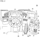
- the inside of the cab 15 is shown as a cab 20 (see Fig. 2 ) for an operator.
- a driver's seat 21, a steering wheel 22, an accelerator pedal 23, a brake pedal 24, a back monitor 25 and an operation device 30 are provided in the cab 20.
- a cigarette lighter 26, a power window switch 27 and a side lamp switch 28 are disposed in the cab 20 on the right side of the operation device 30.
- An option switch 29 such as a fog lamp switch, a rotary light switch, and the like, may be disposed in the cab 20 on the right side of the operation device 30.
- the driver's seat 21 is provided in the cab 15 at a center of the cab 20 in the vehicle width direction.
- the driver's seat 21 is disposed such that an operator sitting on the driver's seat 21 can see a side in front of the dump truck 1 (see Fig. 1 ).
- the steering wheel 22 is provided at a center of the cab 20 in the vehicle width direction.
- the steering wheel 22 is disposed at a side in front of the driver's seat 21 of the vehicle and obliquely above when seen from the seat surface of the driver's seat 21.
- the accelerator pedal 23 is disposed at a side in front of the driver's seat 21 of the vehicle and on the right side of the lower portion.
- the brake pedal 24 is disposed at a side in front of the driver's seat 21 of the vehicle and on the left side of the accelerator pedal 23, which is the right side of the lower portion.
- the back monitor 25 is a display section configured to display an aspect behind the dump truck 1, i.e., an aspect behind the load-carrying platform 6 (see Fig. 1 ) of the vehicle.
- the back monitor 25 is disposed on the right side of the steering wheel 22.
- the operation device 30 is disposed in the vicinity of a side below the back monitor 25, which is on the right side of the steering wheel 22.
- the operation device 30 includes a device main body 31, a shift lever 32 (a gearshift instruction part), a hoist switch 33 (an elevating/lowering instruction part), a parking brake switch 34, a hoist switch lock knob 35 and a guard section 36.
- the device main body 31 is a part that forms an appearance of the operation device 30. As shown in Fig. 3 , the device main body 31 includes a base section 40, a first step portion 41 and a second step portion 42.
- the above-mentioned lever and the like are disposed in the device main body 31.
- the base section 40 has a rectangular shape in which a longitudinal direction is the vehicle forward/rearward direction and a short side direction is the vehicle width direction.
- the longitudinal direction of the base section 40 is referred to as “the forward/rearward direction of the base section 40” or simply as “the forward/rearward direction.”
- the short direction of the base section 40 is referred to as “the widthwise direction of the base section 40” or simply as “the widthwise direction.”
- the base section 40 includes an overhanging section 43 overhanging rightward from the front portion of the base section 40 in the widthwise direction.
- the base section 40 has a hole section 40h that opens in an upper surface of the rear portion of the base section 40 and accommodates a part of the parking brake switch 34.
- the first step portion 41 is provided on the upper portion of the base section 40.
- the first step portion 41 extends over a central portion and a front portion of the base section 40 in the forward/rearward direction.
- a rear portion of the first step portion 41 is continuous with an upper surface of the rear portion of the base section 40 to form a surface.
- the base section 40 has a first rear inclined surface 41a inclined from a rear portion of the first step portion 41 toward the upper surface of the rear portion of the base section 40.
- the first rear inclined surface 41a is inclined to be disposed downward as it goes rearward when seen in a side view from a left side in the widthwise direction (hereinafter, when seen in a side view).
- a left side portion of the first step portion 41 has a first side inclined surface 41b inclined to be continuous with a left side surface of the base section 40.
- the first side inclined surface 41b is inclined to be disposed downward as it goes leftward when seen in a rear view (see Fig. 7 ).
- the first step portion 41 has a shifting groove section 41h (see Fig. 4 ) that opens in the upper surface of the first step portion 41 and accommodates a part of the shift lever 32.
- the second step portion 42 is provided on an upper portion and a front portion of the first step portion 41.
- a rear portion of the second step portion 42 is continuous with an upper surface of the first step portion 41 to form a surface.
- the base section 40 has a second rear inclined surface 42a inclined from a rear portion of the second step portion 42 toward the upper surface of the first step portion 41.
- the second rear inclined surface 42a is inclined to be disposed downward as it goes rearward when seen in a side view.
- a left side portion of the second step portion 42 has a second side inclined surface 42b inclined to be continuous with the left side portion of the base section 40.
- the second side inclined surface 42b is inclined to be steeper than the first side inclined surface 41b to be disposed downward as it goes leftward when seen in a rear view (see Fig. 7 ).
- the second step portion 42 has a groove section 42h for a knob (see Fig. 4 ) that opens in the upper surface of the second step portion 42 and accommodates a part of the hoist switch lock knob 35.
- the shift lever 32 can change a speed of the dump truck 1 (see Fig. 1 ) by being operated in the forward/rearward direction.
- the shift lever 32 can switch a gear of a transmission (not shown) to a predetermined variable speed level by being operated in the forward/rearward direction.
- the shift lever 32 is operated when it is switched between advance and retreat of the dump truck 1 (see Fig. 1 ).
- the shift lever 32 is operated by a right hand of an operator who is sitting on the driver's seat 21 (see Fig. 2 ).
- the shift lever 32 extends upward via the shifting groove section 41h (see Fig. 4 ) formed in the first step portion 41, and has an L shape when seen in a front view or when seen in a rear view.
- the shift lever 32 is movable in the forward/rearward direction along a horizontal plane using a formation range of the shifting groove section 41h as a moving range (see Fig. 8 ).
- the dump truck 1 is in a state in which the dump truck 1 is able to advance when the shift lever 32 is at a rearward position PD of the shifting groove section 41h in the forward/rearward direction (see Fig. 8 ).
- the dump truck 1 is in a state in which the dump truck 1 is able to retreat when the shift lever 32 is at a forward position PR of the shifting groove section 41h in the forward/rearward direction (see Fig. 8 ).
- the dump truck 1 is in a state in which the dump truck 1 is unable to advance and retreat (a neutral state) when the shift lever 32 is at a central position PN of the shifting groove section 41h in the forward/rearward direction (see Fig. 8 ).
- the central position PN, the forward position PR and the rearward position PD in the moving range of the shift lever 32 may be referred to as a neutral position, a reverse position and a drive position.
- the shift lever 32 is movable between the reverse position moved forward from the neutral position and the drive position moved rearward from the neutral position.
- the shift lever 32 includes an arm section 50, a grip section 51 and a side switch 52.
- the arm section 50 extends in the upward/downward direction via the shifting groove section 41h formed in the first step portion 41.
- the arm section 50 is connected to the device main body 31 to be movable in the forward/rearward direction.
- the grip section 51 extends rightward from an upper end of the arm section 50 in the widthwise direction.
- An outer circumferential surface of the grip section 51 is referred to as a grip surface held by a right hand of an operator who is sitting on the driver's seat 21.
- a lower portion of the grip section 51 is inclined to be disposed upward as it goes rightward when seen in a rear view (see Fig. 7 ).
- the grip section 51 has an installation surface section 51a with an area of the upper surface of the grip section 51 on which the operator's palm can be placed.
- the installation surface section 51a is a smooth surface with no irregularities. When seen in a rear view, the installation surface section 51a is curved to be convex upward (see Fig. 7 ). When seen in a side view, the installation surface section 51a is a plane parallel to the horizontal plane in the forward/rearward direction (see Fig. 5 ).
- the side switch 52 is a switch that makes it possible to move the arm section 50 in the forward/rearward direction by being pressed.
- the side switch 52 is provided on a left side end portion of the grip section 51.
- the side switch 52 is operated by a thumb of a right hand of an operator who is sitting on the driver's seat 21.
- the operator When the operator operates the shift lever 32, the operator puts the palm of the right hand on the installation surface section 51a in the grip section 51 of the shift lever 32 and grips the grip section 51 using a middle finger, a ring finger and a little finger of the right hand.
- a thumb of the right hand will press the side switch 52 in the left side end portion of the grip section 51.
- a forefinger of the right hand is displaced in a folded state in front of the arm section 50.
- the hoist switch 33 is a switch configured to operate elevation of the load-carrying platform 6 of the vehicle rear portion 2.
- the hoist switch 33 is disposed in front of the shift lever 32. When seen in a front view, when looking at a positional relation in the leftward/rightward direction, a position of the hoist switch 33 is disposed at a position overlapping the position of the left side portion of the grip section 51 of the shift lever 32 (see Fig. 6 ).
- the hoist switch 33 is operated by a finger of a right hand of an operator who is sitting on the driver's seat 21.
- the hoist switch 33 can be operated by a fore finger or a middle finger.
- the hoist switch 33 includes a switch main body 60 and a switch knob 61.
- the switch main body 60 is provided on an upper surface of the second step portion 42 of the device main body 31.
- the switch main body 60 has an accommodating concave section 60a (see Fig. 8 ) configured to accommodate a part of the switch knob 61 such that the switch knob 61 can be tilted.
- the accommodating concave section 60a has an arc shape that is concave downward when seen in a side view.
- the switch knob 61 is connected to the switch main body 60 to be pivotable around a rotation axis O extending in the widthwise direction using the rotation axis O as a support point.
- the rotation axis O of the switch knob 61 is parallel to the widthwise direction and perpendicular to the forward/rearward direction.
- the switch knob 61 stands upward from the switch main body 60 at a neutral position P0.
- a thickness of the switch knob 61 in the forward/rearward direction gradually reduces toward a side opposite to the switch main body 60 when seen in a side view.
- Surfaces other than the surface of the switch knob 61 opposite to the accommodating concave section 60a of the switch main body 60 are operation surfaces 62.
- the operation surfaces 62 are operated by a finger (for example, a fore finger or a middle finger) of a right hand of an operator who is sitting on the driver's seat 21.
- the operation surfaces 62 are constituted by an apex 62a, a front operation surface 62b and a rear operation surface 62c.
- the apex 62a is an end portion (a protrusion end portion) of the switch knob 61 opposite to the switch main body 60.
- the apex 62a is a portion that connects the front operation surface 62b and the rear operation surface 62c in the forward/rearward direction.
- the apex 62a extends linearly parallel to the rotation axis O. That is, the apex 62a extends uniformly in the widthwise direction.
- the apex 62a is a portion of the operation surface 62 farthest from the rotation axis O. That is, the apex 62a is present on a circumference about the rotation axis O. The circumference corresponds to a tilting trajectory K1, which will be described below.
- the front operation surface 62b is a surface of the switch knob 61 exposed forward from the accommodating concave section 60a.
- the front operation surface 62b is a surface, a widthwise direction of which is a short direction, while a direction in which the switch knob 61 protrudes is a longitudinal direction.
- the rear operation surface 62c is a surface of the switch knob 61 exposed rearward from the accommodating concave section 60a.
- the rear operation surface 62c is a surface, a widthwise direction of which is a short direction, while a direction in which the switch knob 61 protrudes is a longitudinal direction.
- An interval between the front operation surface 62b and the rear operation surface 62c in the forward/rearward direction gradually decreases toward the apex 62a when seen in a side view.
- the switch knob 61 is pivotable around the rotation axis O between the neutral position P0, a forward inclined position P1 and a rearward inclined position P2.
- the neutral position P0 is a position at which the switch knob 61 is tilted neither forward nor rearward.
- the switch knob 61 is at the neutral position P0, it is referred to as a state in which the load-carrying platform 6 is unable to be raised and lowered (a holding state of the load-carrying platform 6 or a state in which the load-carrying platform 6 can be raised or lowered by an external force without being restrained, hereinafter, referred to as "a neutral state").
- the forward inclined position P1 is a position at which the switch knob 61 is tilted forward from the neutral position P0.
- the switch knob 61 is at the forward inclined position P1, the load-carrying platform 6 is in a state in which it can be lowered.
- the rearward inclined position P2 is a position at which the switch knob 61 is tilted rearward from the neutral position P0.
- the switch knob 61 is at the rearward inclined position P2
- the load-carrying platform 6 is in a state in which it can be raised.
- the operation surfaces 62 are exposed on sides (an upper side, a front side and a rear side) opposite to the switch main body 60 from the accommodating concave section 60a.
- a height H1 of the apex of the hoist switch 33 at the neutral position P0 is higher than a height H2 of the upper surface of the shift lever 32 (H1 > H2).
- the height H1 of the apex of the hoist switch 33 at the neutral position P0 means an upper end position of the apex 62a of the switch knob 61 in the hoist switch 33 at the neutral position P0.
- the height H2 of the upper surface of the shift lever 32 means an upper end position of the installation surface section 51a of the grip section 51 in the shift lever 32.
- a position of the rotation axis O of the hoist switch 33 remains in place regardless of the position of the shift lever 32 in the forward/rearward direction.
- the hoist switch 33 does not move integrally with the shift lever 32 according to movement of the shift lever 32 in the forward/rearward direction. Since the switch knob 61 of the hoist switch 33 is in place, when the shift lever 32 moves in the forward/rearward direction, an interval between the shift lever 32 and the hoist switch 33 in the forward/rearward direction is varied. That is, a relative position between the shift lever 32 and the hoist switch 33 in the forward/rearward direction varies according to movement of the shift lever 32 in the forward/rearward direction.
- the parking brake switch 34 is a switch configured to stop the dump truck 1. As shown in Fig. 4 , the parking brake switch 34 is disposed behind the shift lever 32. The parking brake switch 34 is a so-called seesaw switch that is tiltable with respect to the device main body 31 forward or rearward around an axis (not shown) extending in the widthwise direction. The parking brake switch 34 is operated by a right hand of an operator who is sitting on the driver's seat 21.
- the hoist switch lock knob 35 is a switch configured to disable (lock) the hoist switch 33.
- the hoist switch lock knob 35 is disposed on the right side of the hoist switch 33.
- the hoist switch lock knob 35 is a so-called seesaw switch that is tiltable with respect to the device main body 31 forward or rearward about an axis (not shown) extending in the widthwise direction.
- the hoist switch lock knob 35 is operated by a right hand of an operator who is sitting on the driver's seat 21.
- the guard section 36 is a wall section configured to prevent the operator's hand or finger from inadvertently touching the hoist switch 33 when the operator operates a lever or the like other than the hoist switch 33 (for example, operates only the shift lever 32) or when the hand or finger moves in the vicinity of the hoist switch 33 in a state in which the operator is not willing to operate the hoist switch 33.
- the guard section 36 is provided on the upper surface of the second step portion 42 of the device main body 31.
- the guard section 36 is formed integrally with the same member as the device main body 31.
- the guard section 36 includes a rear wall section 70 (a partitioning part) and sidewall sections 71 and 72 (side partitioning parts).
- the guard section 36 when seen in a plan view, is formed in a U shape that opens forward. Further, the guard section 36 may further include a front wall section and have a rectangular shape when seen in a plan view.
- the guard section 36 is disposed outside of a range of the tilting trajectory K1 of the hoist switch 33 (see Fig. 8 ). That is, the tilting trajectory K1 of the hoist switch 33 is further inward than the edge of the guard section 36.
- the rear wall section 70 is a portion of the guard section 36 that partitions a space between the shift lever 32 and the hoist switch 33 in the forward/rearward direction.
- the rear wall section 70 is disposed behind the hoist switch 33.
- the rear wall section 70 is disposed at a position that overlaps the hoist switch 33 and the shift lever 32 in the leftward/rightward direction and the upward/downward direction when seen in a front view (see Fig. 6 ).
- the rear wall section 70 has a rectangular shape, in which a direction in which the switch knob 61 protrudes is a short direction, and a widthwise direction is a longitudinal direction. A length of the rear wall section 70 in the widthwise direction is greater than a length of the switch knob 61 in the widthwise direction.
- the rear wall section 70 When seen in a cross-sectional view perpendicular to the rotation axis O, the rear wall section 70 has a linear shape inclined to be disposed forward as it goes upward (see Fig. 8 ).
- An upper end of the rear wall section 70 is disposed above the rotation axis O. When seen in a plan view, the upper end of the rear wall section 70 is parallel to the widthwise direction and has a linear shape (see Fig. 4 ).
- a height H3 of the rear wall section 70 is lower than the height H2 of the upper surface of the shift lever 32.
- the height of the rear wall section 70 means an upper end position of the rear wall section 70.
- the rear wall section 70 is disposed outside the range of the tilting trajectory K1 of the hoist switch 33.
- the upper end of the rear wall section 70 is disposed at an interval with the rear operation surface 62c of the switch knob 61 at the rearward inclined position P2.
- the sidewall sections 71 and 72 are portions of the guard section 36 located on left and right sides of the hoist switch 33 in the widthwise direction. As shown in Fig. 4 , the sidewall sections 71 and 72 are constituted by a left sidewall section 71 and a right sidewall section 72. The left sidewall section 71 is a portion disposed on the left side of the hoist switch 33. The right sidewall section 72 is a portion disposed on the right side of the hoist switch 33.
- the left side sidewall section 71 is disposed at an interval with the left side surface of the hoist switch 33. When seen in a side view, the left sidewall section 71 is disposed to cover the switch knob 61 (see Fig. 8 ) at the neutral position P0 (see Fig. 5 ). As shown in Fig. 5 , the left sidewall section 71 has a trapezoidal shape in which a length in the forward/rearward direction is decreased as it goes upward to cover the entire switch knob 61 (see Fig. 8 ) at the neutral position P0 and the forward inclined position P1.
- the left sidewall section 71 has a trapezoidal shape having an upper base extending linearly in the forward/rearward direction at a position above the apex 62a of the switch knob 61 at the neutral position P0 and a lower base extending linearly along the upper surface of the second step portion 42 of the device main body 31 and in the forward/rearward direction.
- the right sidewall section 72 has a trapezoidal shape that overlaps an appearance of the left sidewall section 71.
- a left end portion of the rear wall section 70 in the widthwise direction is coupled to a rear lower portion of the left sidewall section 71.
- a right end portion of the rear wall section 70 in the widthwise direction is coupled to a rear lower portion of the right sidewall section 72. Further, when the switch knob 61 is at the forward inclined position P1, the switch knob 61 may be disposed to be visible outside the trapezoidal shape of the left sidewall section 71 or the right sidewall section 72 when seen in a side view. The guard section 36 may not have to prevent even a wrong operation such as an operation of the switch knob 61 to the forward inclined position P1.
- an interval L1 between the shift lever 32 at the forward position PR and the hoist switch 33 at the rearward inclined position P2 in the forward/rearward direction is preferably at least several tens mm or more.
- the interval L1 means an interval (a shortest distance) between a front end of the grip section 51 of the shift lever 32 at the forward position PR and a rear end of the apex 62a of the hoist switch 33 at the rearward inclined position P2 in the forward/rearward direction.
- the interval L1 preferably has a size such that a fore finger of a right hand folded not to touch the hoist switch 33 at the rearward inclined position P2 can be disposed behind the rear wall section 70 when the fore finger is folded forward and downward in a state in which the operator places the palm of the right hand on the installation surface section 51a of the shift lever 32 at the forward position PR.
- An interval L2 between the shift lever 32 at the rearward position PD and the hoist switch 33 at the neutral position P0 in the forward/rearward direction is preferably greater than at least the interval L1 and equal to or less than several tens mm.
- the interval L2 means an interval (shortest distance) between a rear end of the grip section 51 of the shift lever 32 at the rearward position PD and an upper end of the apex 62a of the hoist switch 33 at the neutral position P0 in the forward/rearward direction.
- the interval L2 is preferably a size at which the fore finger of the right hand can extend forward and put the belly of the fore finger on the apex 62a of the hoist switch 33 at the neutral position P0 in a state in which the operator places the palm of the right hand on the installation surface section 51a of the shift lever 32 at the rearward position PD.
- Reference sign 80 in the drawings designates an outline that imitates the right hand of a Japanese woman (for example, a small woman).
- Reference sign L0 in the drawings designates a length of the right hand 80 of the Japanese woman in the forward/rearward direction.
- a length L3 of the shift lever 32 in the forward/rearward direction is set to be greater than a movement pitch L4 of the shift lever 32 in the forward/rearward direction (in the example shown, an interval between a front end of the shift lever 32 at the central position PN and a front end of the shift lever 32 at the forward position PR in the forward/rearward direction).
- a load such as earth or the like can be loaded on the load-carrying platform 6 of the dump truck 1.
- the operator of the dump truck 1 moves the dump truck 1 to a predetermined place, and performs a work of dumping a load on the load-carrying platform 6 (a dump work).
- a dump work For example, when the operator operates the dump truck 1 to perform a dump work, movement of the operator's hand is a procedure from the following (1) to (3).
- the hoist switch 33 is disposed near the front of the shift lever 32.
- the operator can operate the hoist switch 33 without greatly moving the right hand when the right hand is moved from the shift lever 32 toward the hoist switch 33. That is, in the embodiment, since the interval between the shift lever 32 and the hoist switch 33 in the forward/rearward direction is small, the operator can easily operate the hoist switch 33 after the operation of the shift lever 32. Accordingly, tired feeling due to the burden of the right hand of the operator can be reduced.
- the hoist switch 33 that is a switch type, which is not a hoist lever that is a lever type, is employed as the elevating/lowering instruction part. For this reason, the hoist switch 33 can be easily operated with the finger of the right hand.
- the operator may need to move his/her hand in various directions.
- the operator may operate only the shift lever 32 without operating the hoist switch 33.
- the hand or finger may inadvertently touch the hoist switch 33, which causes the load-carrying platform 6 to malfunction.
- the rear wall section 70 configured to partition the space between the shift lever 32 and the hoist switch 33 in the forward/rearward direction is provided.
- the height H1 of the apex 62a of the hoist switch 33 at the neutral position P0 is higher than the height H2 of the upper surface of the shift lever 32 (H1 > H2).
- the upper surface of the shift lever 32 has the installation surface section 51a (a plane).
- the shift lever 32 can also function as a palm rest.
- the operator can operate the hoist switch 33 while placing the right hand on the shift lever 32.
- the shift lever 32 functions as a palm rest, since the chances of the wrong operation of the hoist switch 33 increases, the configuration of the embodiment, which minimizes the wrong operation of the hoist switch 33, has great practical benefits.
- the shift lever 32 is movable along the horizontal plane in the forward/rearward direction.
- the hoist switch 33 does not move integrally with the shift lever 32 according to movement of the shift lever 32 in the forward/rearward direction. That is, a relative position between the shift lever 32 and the hoist switch 33 in the forward/rearward direction is varied according to movement of the shift lever 32 in the forward/rearward direction.
- the relative position between the shift lever 32 and the hoist switch 33 in the forward/rearward direction is varied, since the chances of the wrong operation of the hoist switch 33 increases, the configuration of the embodiment, which minimizes the wrong operation of the hoist switch 33, has great practical benefits.
- the operation device 30 includes the sidewall sections 71 and 72 disposed beside the hoist switch 33 in the widthwise direction.
- the sidewall sections 71 and 72 are constituted by the left sidewall section 71 located on the left side of the hoist switch 33 and the right sidewall section 72 located on the right side of the hoist switch 33. For this reason, when the operator operates a lever or the like other than the hoist switch 33, it is possible to prevent the right hand from touching the hoist switch 33 from both sides in the widthwise direction.
- a height of the sidewall sections 71 and 72 is greater than the height of the apex 62a of the hoist switch 33 at the neutral position P0. For this reason, it is possible to minimize the wrong operation of the hoist switch 33 from above.
- the sidewall sections 71 and 72 are disposed to cover the hoist switch 33 at the neutral position P0.
- the hoist switch 33 is pivotable around the rotation axis O extending in the widthwise direction between the forward inclined position P1 tilted forward from the neutral position P0 and the rearward inclined position P2 tilted rearward from the neutral position P0.
- the upper end of the rear wall section 70 is located above the rotation axis O of the hoist switch 33.
- the configuration it is possible to cover at least a part of a portion (the rear operation surface 62c) of the hoist switch 33 that contributes to the operation of the hoist switch 33 by the rear wall section 70 from behind. Accordingly, it is possible to more effectively minimize the wrong operation of the hoist switch 33.
- the rear wall section 70 is disposed outside the range of the tilting trajectory K1 of the hoist switch 33.
- the hoist switch 33 when the hoist switch 33 is tilted, the hoist switch 33 does not touch the rear wall section 70. That is, the rear wall section 70 does not interfere with the operation of the hoist switch 33. Accordingly, operability of the hoist switch 33 can be secured.
- the interval L1 between the shift lever 32 at the forward position PR and the hoist switch 33 at the rearward inclined position P2 in the forward/rearward direction is equal to or greater than at least tens mm. In this case, in comparison with the case in which the interval L1 is short, it is easy to minimize the wrong operation of the hoist switch 33.
- the interval L2 between the shift lever 32 at the rearward position PD and the hoist switch 33 at the neutral position P0 in the forward/rearward direction is greater than at least the interval L1 and equal to or less than tens mm.
- the operator can operate the hoist switch 33 with the fore finger of the right hand while placing the palm of the right hand on the shift lever 32 at the neutral position P0 and a drive position PD at which a frequency of use is higher than at a reverse position PR of the shift lever 32.
- the height H3 of the rear wall section 70 is less than the height H2 of the upper surface of the shift lever 32.
- the rear wall section 70 is disposed at a position overlapping the hoist switch 33 and the shift lever 32 in the leftward/rightward direction and the upward/downward direction when seen in the forward/rearward direction.
- the hoist switch 33 is disposed at a position overlapping the shift lever 32 in the leftward/rightward direction and the upward/downward direction when seen in the forward/rearward direction. For this reason, it is easy to operate the hoist switch 33 in front of the shift lever 32 after the operation of the shift lever 32. Accordingly, it is possible to minimize the wrong operation of the hoist switch 33 while securing the operability of the hoist switch 33.
- the operation device 30 is disposed near the bottom of the back monitor 25 located on the right side of the steering wheel 22.
- the operator can see the back monitor 25 by moving his/her gaze slightly while looking at the right hand. For example, it is possible to easily see the situation behind the vehicle projected on the back monitor 25 while operating the operation device 30 in the case in which the situation behind the dump truck 1 is desired to be recognized when the operator hoist-operates the load-carrying platform 6.
- the operation device 30 is disposed on the right side of the steering wheel 22, in which the left side of the steering wheel 22 is set as one side in the vehicle width direction (one side in the leftward/rightward direction) and the right side of the steering wheel 22 is set as the other side in the vehicle width direction (the other side in the leftward/rightward direction) has been exemplarily described in the above-mentioned embodiment, there is no limitation thereto.
- the operation device 30 may be disposed on the left side of the steering wheel 22.
- the steering wheel 22 may be disposed on the left side of the vehicle, which is one side in the vehicle width direction.
- the driver's seat 21 is disposed on the left side of the vehicle.
- the central position PN, the forward position PR and the rearward position PD within the moving range of the shift lever 32 may be set as a neutral position, a drive position and a reverse position.
- the shift lever 32 is movable between the reverse position moved rearward from the neutral position and the drive position moved forward from the neutral position.
- the drive position may be set by switching a plurality of variable speed levels, in addition to the rearward position PD.
- the examples corresponding to the neutral state the state in which the load-carrying platform 6 can be lowered and the state in which the load-carrying platform 6 can be raised in the cases in which the hoist switch 33 is at the neutral position P0, at the forward inclined position P1 and at the rearward inclined position P2 have been exemplarily described in the above-mentioned embodiment, there is no limitation thereto.
- the examples may correspond to the neutral state, the state in which the load-carrying platform 6 can be raised and the state in which the load-carrying platform 6 can be lowered in the cases in which the hoist switch 33 is at the neutral position P0, at the forward inclined position P1 and at the rearward inclined position P2. That is, an operation that enables elevation of the load-carrying platform 6 may be the opposite of the embodiment according to a forward inclination operation and a rearward inclination operation of the hoist switch 33.
- the guard section 36 is formed integrally with the same member as the device main body 31
- the guard section 36 may be formed integrally with a member different from the device main body 31.
- a guard member as a guard section manufactured individually from the device main body 31 is attached to the device main body 31.
- the height H1 of the apex 62a of the hoist switch 33 at the neutral position P0 is greater than the height H2 of the upper surface of the shift lever 32
- the height H1 of the apex 62a of the hoist switch 33 at the neutral position P0 may be equal to or less than the height H2 of the upper surface of the shift lever 32.
- the upper surface of the shift lever 32 has the installation surface section 51a with an area in which the palm of the operator can be placed
- the upper surface of the shift lever 32 may have an area in which the palm of the operator can be placed.
- the shift lever 32 may be movable in a direction obliquely crossing the horizontal plane.
- the shift lever 32 may be pivotable (movable in an arc shape) around the rotation axis extending in the widthwise direction (the direction perpendicular to the forward/rearward direction).
- the operation device 30 may not include the sidewall sections 71 and 72. That is, the operation device 30 may include only the rear wall section 70 as the guard section 36.
- the hoist switch 33 may be a button type that can be pressed from above.
- the upper end of the rear wall section 70 is disposed above an operated surface of the button (for example, an upper surface of the button).
- the height H3 of the rear wall section 70 is smaller than the height H2 of the upper surface of the shift lever 32
- the height H3 of the rear wall section 70 may be equal to or greater than the height H2 of the upper surface of the shift lever 32.
- the rear wall section 70 may have a rod shape extending in a direction in which the switch knob 61 protrudes. That is, the rear wall section 70 may function as a partitioning part that partitions a space between the shift lever 32 and the hoist switch 33 in the forward/rearward direction.
- the present invention may be applied to another work vehicle such as a rigid frame type dump truck or the like.
Landscapes
- Engineering & Computer Science (AREA)
- Transportation (AREA)
- Mechanical Engineering (AREA)
- Chemical & Material Sciences (AREA)
- Combustion & Propulsion (AREA)
- Mining & Mineral Resources (AREA)
- Civil Engineering (AREA)
- General Engineering & Computer Science (AREA)
- Structural Engineering (AREA)
- Arrangement Or Mounting Of Control Devices For Change-Speed Gearing (AREA)
- Mechanical Control Devices (AREA)
Abstract
Description
- The present invention relates to an operation device and a work vehicle.
- Priority is claimed on
Japanese Patent Application No. 2019-164244, filed September 10, 2019 - As a work vehicle, a transportation vehicle that operates at a stone-crushing site, a civil engineering site, a mine, or the like, is known. An operator of the transportation vehicle performs a steering wheel operation, a shift lever operation, a dump lever (hoist lever) operation, an accelerator/brake operation, and the like, in a loading station or a dump site.
- The transportation vehicle includes a load-carrying platform, which is able to elevate, referred to as a body. A load such as earth can be loaded on the load-carrying platform. For an operation device of the transportation vehicle, a configuration including a gearshift instruction part configured to change a speed of the transportation vehicle by being manipulated in a forward/rearward direction and an elevating/lowering instruction part disposed in front of the gearshift instruction part and configured to operate elevation of the load-carrying platform is known as an example.
- For example, the following
Patent Document 1 discloses a configuration of having an operation lever that is pivotable (movable in an arc shape) around a rotation axis extending in a widthwise direction (a direction perpendicular to the forward/rearward direction), a knob main body coupled to an upper end portion of the operation lever, and a movable switch disposed in front of the knob main body. The movable switch is moved integrally with the knob main body (moved in an arc shape) according to the arc-shaped movement of the operation lever. A space that allows communication between the side of the knob main body and the side of the movable switch is provided between the knob main body and the movable switch in the forward/rearward direction. - [Patent Document 1]
US Patent No. 9086130 - An operator of a work vehicle moves a work vehicle to a predetermined place to perform a work of dumping a load of a load-carrying platform (dump work). For example, when the dump work is performed, movement of the operator's hand is the following procedure from (1) to (3).
- (1) Moving the vehicle to a dump place while holding a steering wheel with the hands and operating the steering wheel.
- (2) Operating a shift lever (a gearshift instruction part) when the vehicle stops at the dump place.
- (3) Operating a hoist lever (an elevating/lowering instruction part) to hoist-operate the load-carrying platform after the vehicle stops.
- For example, only the gearshift instruction part may be operated without operating the elevating/lowering instruction part. In this case, when a space that brings the side of the gearshift instruction part in communication with the side of the elevating/lowering instruction part is provided, the hands or fingers may inadvertently touch the elevating/lowering instruction part to cause the load-carrying platform to malfunction.
- Here, the present invention is directed to providing an operation device and a work vehicle that are capable of minimizing wrong operations of an elevating/lowering instruction part.
- An operation device according to an aspect of the present invention is an operation device of a work vehicle having a load-carrying platform, which includes a gearshift instruction part configured to change a speed of the work vehicle by being operated in a forward/rearward direction, an elevating/lowering instruction part disposed in front of the gearshift instruction part and configured to operate elevation of the load-carrying platform, and a partitioning part configured to partition a space between the gearshift instruction part and the elevating/lowering instruction part in the forward/rearward direction.
- According to the aspect, it is possible to minimize wrong operations of an elevating/lowering instruction part.
-
-
Fig. 1 is a perspective view of a work vehicle according to an embodiment. -
Fig. 2 is a view showing the inside of a cab of the work vehicle according to the embodiment when seen from behind and above the vehicle. -
Fig. 3 is a perspective view of an operation device of the work vehicle according to the embodiment. -
Fig. 4 is a plan view of the operation device according to the embodiment. -
Fig. 5 is a left side view of the operation device according to the embodiment. -
Fig. 6 is a front view of the operation device according to the embodiment. -
Fig. 7 is a rear view of the operation device according to the embodiment. -
Fig. 8 is a view for describing shift lever and hoist switch operations and disposition intervals of the operation device according to the embodiment. - Hereinafter, an embodiment of the present invention will be described with reference to the accompanying drawings. In the embodiment, an articulated dump truck will be exemplarily described as an example of a work vehicle.
- As shown in
Fig. 1 , adump truck 1 serving as a work vehicle includes a vehiclerear portion 2 and avehicle front portion 3. Hereinafter, a forward direction, a rearward direction and a vehicle width direction of thedump truck 1 are referred to as "toward a side in front of the vehicle (one side in the vehicle forward/rearward direction)," "toward a side behind the vehicle (the other side in the vehicle forward/rearward direction) and "a vehicle width direction." The vehicle width direction may be referred to as a "toward a left side (one side in the vehicle width direction)" or "toward a right side (the other side in the vehicle width direction)." A right hand with respect to a direction in which thedump truck 1 advances is referred to as a right side, and a left hand with respect to the direction in which thedump truck 1 advances is referred to as a left side. An upward/downward direction, and above and below in a state in which thedump truck 1 is disposed on a horizontal plane are simply referred to as "a vertical direction," and "above" and "below." - The vehicle
rear portion 2 includes arear frame section 11, rear front-wheels 13 and rear rear-wheels 14. Therear frame section 11 constitutes a frame of the vehiclerear portion 2. The vehiclerear portion 2 is provided behind thevehicle front portion 3 of the vehicle. The vehiclerear portion 2 includes a hoist cylinder 5 and a load-carryingplatform 6. One end of the hoist cylinder 5 is pivotably connected to therear frame section 11 of the vehiclerear portion 2 via a bracket (not shown). The load-carryingplatform 6 is connected to the other end of the hoist cylinder 5 via a bracket (not shown). The load-carryingplatform 6 is driven by the hoist cylinder 5. The hoist cylinder 5 is driven by a hydraulic pressure supplied via a hydraulic circuit (not shown). - The
vehicle front portion 3 includes afront frame section 10,front wheels 12 and acab 15. - The
front frame section 10 constitutes a frame of thevehicle front portion 3. Therear frame section 11 is connected to a side behind thefront frame section 10 of the vehicle by a connecting member (not shown). Thefront frame section 10 and therear frame section 11 are made pivotable with respect to each other in the horizontal direction by connecting them around an axis extending in the upward/downward direction. When thefront frame section 10 and therear frame section 11 advance or reverse while being pivoted relatively, thevehicle front portion 3 of thedump truck 1 swings rightward or leftward (right swing or left swing). Further, thefront frame section 10 and therear frame section 11 are pivotable independently from each other around the axis extending in the forward/rearward direction via the connecting member (not shown). - The pair of
front wheels 12 are provided on thefront frame section 10 separately in the vehicle width direction. The pair of rear front-wheels 13 are provided on a front portion of therear frame section 11 separately in the vehicle width direction. The pair of rear rear-wheels 14 are provided on a rear portion of therear frame section 11 separately in the vehicle width direction. When thefront wheels 12, the rear front-wheels 13 and the rear rear-wheels 14 are driven, thedump truck 1 advances and retreats. - The
cab 15 is provided on a rear portion and an upper portion of thefront frame section 10. The inside of thecab 15 is shown as a cab 20 (seeFig. 2 ) for an operator. As shown inFig. 2 , a driver'sseat 21, asteering wheel 22, anaccelerator pedal 23, abrake pedal 24, aback monitor 25 and anoperation device 30 are provided in thecab 20. - A cigarette lighter 26, a
power window switch 27 and aside lamp switch 28 are disposed in thecab 20 on the right side of theoperation device 30. Anoption switch 29 such as a fog lamp switch, a rotary light switch, and the like, may be disposed in thecab 20 on the right side of theoperation device 30. - The driver's
seat 21 is provided in thecab 15 at a center of thecab 20 in the vehicle width direction. The driver'sseat 21 is disposed such that an operator sitting on the driver'sseat 21 can see a side in front of the dump truck 1 (seeFig. 1 ). - The
steering wheel 22 is provided at a center of thecab 20 in the vehicle width direction. Thesteering wheel 22 is disposed at a side in front of the driver'sseat 21 of the vehicle and obliquely above when seen from the seat surface of the driver'sseat 21. - The
accelerator pedal 23 is disposed at a side in front of the driver'sseat 21 of the vehicle and on the right side of the lower portion. - The
brake pedal 24 is disposed at a side in front of the driver'sseat 21 of the vehicle and on the left side of theaccelerator pedal 23, which is the right side of the lower portion. - The back monitor 25 is a display section configured to display an aspect behind the
dump truck 1, i.e., an aspect behind the load-carrying platform 6 (seeFig. 1 ) of the vehicle. For example, theback monitor 25 is disposed on the right side of thesteering wheel 22. - The
operation device 30 is disposed in the vicinity of a side below theback monitor 25, which is on the right side of thesteering wheel 22. Theoperation device 30 includes a devicemain body 31, a shift lever 32 (a gearshift instruction part), a hoist switch 33 (an elevating/lowering instruction part), aparking brake switch 34, a hoistswitch lock knob 35 and aguard section 36. - The device
main body 31 is a part that forms an appearance of theoperation device 30. As shown inFig. 3 , the devicemain body 31 includes abase section 40, afirst step portion 41 and asecond step portion 42. The above-mentioned lever and the like (theshift lever 32, the hoistswitch 33, theparking brake switch 34 and the hoist switch lock knob 35) are disposed in the devicemain body 31. - As shown in
Fig. 4 , thebase section 40 has a rectangular shape in which a longitudinal direction is the vehicle forward/rearward direction and a short side direction is the vehicle width direction. Hereinafter, the longitudinal direction of thebase section 40 is referred to as "the forward/rearward direction of thebase section 40" or simply as "the forward/rearward direction." In addition, the short direction of thebase section 40 is referred to as "the widthwise direction of thebase section 40" or simply as "the widthwise direction." Thebase section 40 includes an overhangingsection 43 overhanging rightward from the front portion of thebase section 40 in the widthwise direction. Thebase section 40 has ahole section 40h that opens in an upper surface of the rear portion of thebase section 40 and accommodates a part of theparking brake switch 34. - As shown in
Fig. 5 , thefirst step portion 41 is provided on the upper portion of thebase section 40. Thefirst step portion 41 extends over a central portion and a front portion of thebase section 40 in the forward/rearward direction. A rear portion of thefirst step portion 41 is continuous with an upper surface of the rear portion of thebase section 40 to form a surface. Thebase section 40 has a first rearinclined surface 41a inclined from a rear portion of thefirst step portion 41 toward the upper surface of the rear portion of thebase section 40. The first rearinclined surface 41a is inclined to be disposed downward as it goes rearward when seen in a side view from a left side in the widthwise direction (hereinafter, when seen in a side view). A left side portion of thefirst step portion 41 has a first side inclinedsurface 41b inclined to be continuous with a left side surface of thebase section 40. The first side inclinedsurface 41b is inclined to be disposed downward as it goes leftward when seen in a rear view (seeFig. 7 ). Thefirst step portion 41 has a shiftinggroove section 41h (seeFig. 4 ) that opens in the upper surface of thefirst step portion 41 and accommodates a part of theshift lever 32. - As shown in
Fig. 5 , thesecond step portion 42 is provided on an upper portion and a front portion of thefirst step portion 41. A rear portion of thesecond step portion 42 is continuous with an upper surface of thefirst step portion 41 to form a surface. Thebase section 40 has a second rearinclined surface 42a inclined from a rear portion of thesecond step portion 42 toward the upper surface of thefirst step portion 41. The second rearinclined surface 42a is inclined to be disposed downward as it goes rearward when seen in a side view. A left side portion of thesecond step portion 42 has a second side inclinedsurface 42b inclined to be continuous with the left side portion of thebase section 40. The second side inclinedsurface 42b is inclined to be steeper than the first side inclinedsurface 41b to be disposed downward as it goes leftward when seen in a rear view (seeFig. 7 ). Thesecond step portion 42 has agroove section 42h for a knob (seeFig. 4 ) that opens in the upper surface of thesecond step portion 42 and accommodates a part of the hoistswitch lock knob 35. - The
shift lever 32 can change a speed of the dump truck 1 (seeFig. 1 ) by being operated in the forward/rearward direction. Theshift lever 32 can switch a gear of a transmission (not shown) to a predetermined variable speed level by being operated in the forward/rearward direction. Theshift lever 32 is operated when it is switched between advance and retreat of the dump truck 1 (seeFig. 1 ). Theshift lever 32 is operated by a right hand of an operator who is sitting on the driver's seat 21 (seeFig. 2 ). - As shown in
Fig. 7 , theshift lever 32 extends upward via the shiftinggroove section 41h (seeFig. 4 ) formed in thefirst step portion 41, and has an L shape when seen in a front view or when seen in a rear view. Theshift lever 32 is movable in the forward/rearward direction along a horizontal plane using a formation range of the shiftinggroove section 41h as a moving range (seeFig. 8 ). - The
dump truck 1 is in a state in which thedump truck 1 is able to advance when theshift lever 32 is at a rearward position PD of the shiftinggroove section 41h in the forward/rearward direction (seeFig. 8 ). - The
dump truck 1 is in a state in which thedump truck 1 is able to retreat when theshift lever 32 is at a forward position PR of the shiftinggroove section 41h in the forward/rearward direction (seeFig. 8 ). - The
dump truck 1 is in a state in which thedump truck 1 is unable to advance and retreat (a neutral state) when theshift lever 32 is at a central position PN of the shiftinggroove section 41h in the forward/rearward direction (seeFig. 8 ). - Hereinafter, the central position PN, the forward position PR and the rearward position PD in the moving range of the
shift lever 32 may be referred to as a neutral position, a reverse position and a drive position. Theshift lever 32 is movable between the reverse position moved forward from the neutral position and the drive position moved rearward from the neutral position. - As shown in
Fig. 3 , theshift lever 32 includes anarm section 50, agrip section 51 and aside switch 52. - The
arm section 50 extends in the upward/downward direction via the shiftinggroove section 41h formed in thefirst step portion 41. Thearm section 50 is connected to the devicemain body 31 to be movable in the forward/rearward direction. - The
grip section 51 extends rightward from an upper end of thearm section 50 in the widthwise direction. An outer circumferential surface of thegrip section 51 is referred to as a grip surface held by a right hand of an operator who is sitting on the driver'sseat 21. A lower portion of thegrip section 51 is inclined to be disposed upward as it goes rightward when seen in a rear view (seeFig. 7 ). - The
grip section 51 has aninstallation surface section 51a with an area of the upper surface of thegrip section 51 on which the operator's palm can be placed. Theinstallation surface section 51a is a smooth surface with no irregularities. When seen in a rear view, theinstallation surface section 51a is curved to be convex upward (seeFig. 7 ). When seen in a side view, theinstallation surface section 51a is a plane parallel to the horizontal plane in the forward/rearward direction (seeFig. 5 ). - The
side switch 52 is a switch that makes it possible to move thearm section 50 in the forward/rearward direction by being pressed. Theside switch 52 is provided on a left side end portion of thegrip section 51. Theside switch 52 is operated by a thumb of a right hand of an operator who is sitting on the driver'sseat 21. - When the operator operates the
shift lever 32, the operator puts the palm of the right hand on theinstallation surface section 51a in thegrip section 51 of theshift lever 32 and grips thegrip section 51 using a middle finger, a ring finger and a little finger of the right hand. Here, a thumb of the right hand will press theside switch 52 in the left side end portion of thegrip section 51. For example, a forefinger of the right hand is displaced in a folded state in front of thearm section 50. - The hoist
switch 33 is a switch configured to operate elevation of the load-carryingplatform 6 of the vehiclerear portion 2. The hoistswitch 33 is disposed in front of theshift lever 32. When seen in a front view, when looking at a positional relation in the leftward/rightward direction, a position of the hoistswitch 33 is disposed at a position overlapping the position of the left side portion of thegrip section 51 of the shift lever 32 (seeFig. 6 ). The hoistswitch 33 is operated by a finger of a right hand of an operator who is sitting on the driver'sseat 21. For example, the hoistswitch 33 can be operated by a fore finger or a middle finger. - The hoist
switch 33 includes a switchmain body 60 and aswitch knob 61. - The switch
main body 60 is provided on an upper surface of thesecond step portion 42 of the devicemain body 31. The switchmain body 60 has an accommodatingconcave section 60a (seeFig. 8 ) configured to accommodate a part of theswitch knob 61 such that theswitch knob 61 can be tilted. As shown inFig. 8 , the accommodatingconcave section 60a has an arc shape that is concave downward when seen in a side view. - The
switch knob 61 is connected to the switchmain body 60 to be pivotable around a rotation axis O extending in the widthwise direction using the rotation axis O as a support point. The rotation axis O of theswitch knob 61 is parallel to the widthwise direction and perpendicular to the forward/rearward direction. - The
switch knob 61 stands upward from the switchmain body 60 at a neutral position P0. A thickness of theswitch knob 61 in the forward/rearward direction gradually reduces toward a side opposite to the switchmain body 60 when seen in a side view. Surfaces other than the surface of theswitch knob 61 opposite to the accommodatingconcave section 60a of the switch main body 60 (surfaces on an upper side, a front side and a rear side) are operation surfaces 62. The operation surfaces 62 are operated by a finger (for example, a fore finger or a middle finger) of a right hand of an operator who is sitting on the driver'sseat 21. - The operation surfaces 62 are constituted by an apex 62a, a
front operation surface 62b and arear operation surface 62c. - The apex 62a is an end portion (a protrusion end portion) of the
switch knob 61 opposite to the switchmain body 60. The apex 62a is a portion that connects thefront operation surface 62b and therear operation surface 62c in the forward/rearward direction. As shown inFig. 6 , the apex 62a extends linearly parallel to the rotation axis O. That is, the apex 62a extends uniformly in the widthwise direction. The apex 62a is a portion of theoperation surface 62 farthest from the rotation axis O. That is, the apex 62a is present on a circumference about the rotation axis O. The circumference corresponds to a tilting trajectory K1, which will be described below. - As shown in
Fig. 8 , thefront operation surface 62b is a surface of theswitch knob 61 exposed forward from the accommodatingconcave section 60a. Thefront operation surface 62b is a surface, a widthwise direction of which is a short direction, while a direction in which theswitch knob 61 protrudes is a longitudinal direction. - The
rear operation surface 62c is a surface of theswitch knob 61 exposed rearward from the accommodatingconcave section 60a. Therear operation surface 62c is a surface, a widthwise direction of which is a short direction, while a direction in which theswitch knob 61 protrudes is a longitudinal direction. An interval between thefront operation surface 62b and therear operation surface 62c in the forward/rearward direction gradually decreases toward the apex 62a when seen in a side view. - The
switch knob 61 is pivotable around the rotation axis O between the neutral position P0, a forward inclined position P1 and a rearward inclined position P2. - The neutral position P0 is a position at which the
switch knob 61 is tilted neither forward nor rearward. When theswitch knob 61 is at the neutral position P0, it is referred to as a state in which the load-carryingplatform 6 is unable to be raised and lowered (a holding state of the load-carryingplatform 6 or a state in which the load-carryingplatform 6 can be raised or lowered by an external force without being restrained, hereinafter, referred to as "a neutral state"). - The forward inclined position P1 is a position at which the
switch knob 61 is tilted forward from the neutral position P0. When theswitch knob 61 is at the forward inclined position P1, the load-carryingplatform 6 is in a state in which it can be lowered. - The rearward inclined position P2 is a position at which the
switch knob 61 is tilted rearward from the neutral position P0. When theswitch knob 61 is at the rearward inclined position P2, the load-carryingplatform 6 is in a state in which it can be raised. - Irrespective of whether the
switch knob 61 is at the neutral position P0, the forward inclined position P1 or the rearward inclined position P2, the operation surfaces 62 are exposed on sides (an upper side, a front side and a rear side) opposite to the switchmain body 60 from the accommodatingconcave section 60a. - A height H1 of the apex of the hoist
switch 33 at the neutral position P0 is higher than a height H2 of the upper surface of the shift lever 32 (H1 > H2). Here, the height H1 of the apex of the hoistswitch 33 at the neutral position P0 means an upper end position of the apex 62a of theswitch knob 61 in the hoistswitch 33 at the neutral position P0. The height H2 of the upper surface of theshift lever 32 means an upper end position of theinstallation surface section 51a of thegrip section 51 in theshift lever 32. - A position of the rotation axis O of the hoist
switch 33 remains in place regardless of the position of theshift lever 32 in the forward/rearward direction. The hoistswitch 33 does not move integrally with theshift lever 32 according to movement of theshift lever 32 in the forward/rearward direction. Since theswitch knob 61 of the hoistswitch 33 is in place, when theshift lever 32 moves in the forward/rearward direction, an interval between theshift lever 32 and the hoistswitch 33 in the forward/rearward direction is varied. That is, a relative position between theshift lever 32 and the hoistswitch 33 in the forward/rearward direction varies according to movement of theshift lever 32 in the forward/rearward direction. - The
parking brake switch 34 is a switch configured to stop thedump truck 1. As shown inFig. 4 , theparking brake switch 34 is disposed behind theshift lever 32. Theparking brake switch 34 is a so-called seesaw switch that is tiltable with respect to the devicemain body 31 forward or rearward around an axis (not shown) extending in the widthwise direction. Theparking brake switch 34 is operated by a right hand of an operator who is sitting on the driver'sseat 21. - The hoist
switch lock knob 35 is a switch configured to disable (lock) the hoistswitch 33. The hoistswitch lock knob 35 is disposed on the right side of the hoistswitch 33. The hoistswitch lock knob 35 is a so-called seesaw switch that is tiltable with respect to the devicemain body 31 forward or rearward about an axis (not shown) extending in the widthwise direction. The hoistswitch lock knob 35 is operated by a right hand of an operator who is sitting on the driver'sseat 21. - The
guard section 36 is a wall section configured to prevent the operator's hand or finger from inadvertently touching the hoistswitch 33 when the operator operates a lever or the like other than the hoist switch 33 (for example, operates only the shift lever 32) or when the hand or finger moves in the vicinity of the hoistswitch 33 in a state in which the operator is not willing to operate the hoistswitch 33. As shown inFig. 5 , theguard section 36 is provided on the upper surface of thesecond step portion 42 of the devicemain body 31. For example, theguard section 36 is formed integrally with the same member as the devicemain body 31. As shown inFig. 4 , theguard section 36 includes a rear wall section 70 (a partitioning part) andsidewall sections 71 and 72 (side partitioning parts). That is, when seen in a plan view, theguard section 36 is formed in a U shape that opens forward. Further, theguard section 36 may further include a front wall section and have a rectangular shape when seen in a plan view. Theguard section 36 is disposed outside of a range of the tilting trajectory K1 of the hoist switch 33 (seeFig. 8 ). That is, the tilting trajectory K1 of the hoistswitch 33 is further inward than the edge of theguard section 36. - The
rear wall section 70 is a portion of theguard section 36 that partitions a space between theshift lever 32 and the hoistswitch 33 in the forward/rearward direction. Therear wall section 70 is disposed behind the hoistswitch 33. Therear wall section 70 is disposed at a position that overlaps the hoistswitch 33 and theshift lever 32 in the leftward/rightward direction and the upward/downward direction when seen in a front view (seeFig. 6 ). - The
rear wall section 70 has a rectangular shape, in which a direction in which theswitch knob 61 protrudes is a short direction, and a widthwise direction is a longitudinal direction. A length of therear wall section 70 in the widthwise direction is greater than a length of theswitch knob 61 in the widthwise direction. When seen in a cross-sectional view perpendicular to the rotation axis O, therear wall section 70 has a linear shape inclined to be disposed forward as it goes upward (seeFig. 8 ). An upper end of therear wall section 70 is disposed above the rotation axis O. When seen in a plan view, the upper end of therear wall section 70 is parallel to the widthwise direction and has a linear shape (seeFig. 4 ). - A height H3 of the
rear wall section 70 is lower than the height H2 of the upper surface of theshift lever 32. Here, the height of therear wall section 70 means an upper end position of therear wall section 70. - The
rear wall section 70 is disposed outside the range of the tilting trajectory K1 of the hoistswitch 33. The upper end of therear wall section 70 is disposed at an interval with therear operation surface 62c of theswitch knob 61 at the rearward inclined position P2. - The
sidewall sections guard section 36 located on left and right sides of the hoistswitch 33 in the widthwise direction. As shown inFig. 4 , thesidewall sections left sidewall section 71 and aright sidewall section 72. Theleft sidewall section 71 is a portion disposed on the left side of the hoistswitch 33. Theright sidewall section 72 is a portion disposed on the right side of the hoistswitch 33. - The left
side sidewall section 71 is disposed at an interval with the left side surface of the hoistswitch 33. When seen in a side view, theleft sidewall section 71 is disposed to cover the switch knob 61 (seeFig. 8 ) at the neutral position P0 (seeFig. 5 ). As shown inFig. 5 , theleft sidewall section 71 has a trapezoidal shape in which a length in the forward/rearward direction is decreased as it goes upward to cover the entire switch knob 61 (seeFig. 8 ) at the neutral position P0 and the forward inclined position P1. When seen in a side view, theleft sidewall section 71 has a trapezoidal shape having an upper base extending linearly in the forward/rearward direction at a position above the apex 62a of theswitch knob 61 at the neutral position P0 and a lower base extending linearly along the upper surface of thesecond step portion 42 of the devicemain body 31 and in the forward/rearward direction. When seen in a side view, theright sidewall section 72 has a trapezoidal shape that overlaps an appearance of theleft sidewall section 71. A left end portion of therear wall section 70 in the widthwise direction is coupled to a rear lower portion of theleft sidewall section 71. A right end portion of therear wall section 70 in the widthwise direction is coupled to a rear lower portion of theright sidewall section 72. Further, when theswitch knob 61 is at the forward inclined position P1, theswitch knob 61 may be disposed to be visible outside the trapezoidal shape of theleft sidewall section 71 or theright sidewall section 72 when seen in a side view. Theguard section 36 may not have to prevent even a wrong operation such as an operation of theswitch knob 61 to the forward inclined position P1. - As shown in
Fig. 8 , a space is provided between theshift lever 32 at the forward position PR and the hoistswitch 33 at the rearward inclined position P2 in the forward/rearward direction. For example, an interval L1 between theshift lever 32 at the forward position PR and the hoistswitch 33 at the rearward inclined position P2 in the forward/rearward direction is preferably at least several tens mm or more. Here, the interval L1 means an interval (a shortest distance) between a front end of thegrip section 51 of theshift lever 32 at the forward position PR and a rear end of the apex 62a of the hoistswitch 33 at the rearward inclined position P2 in the forward/rearward direction. - For example, the interval L1 preferably has a size such that a fore finger of a right hand folded not to touch the hoist
switch 33 at the rearward inclined position P2 can be disposed behind therear wall section 70 when the fore finger is folded forward and downward in a state in which the operator places the palm of the right hand on theinstallation surface section 51a of theshift lever 32 at the forward position PR. - An interval L2 between the
shift lever 32 at the rearward position PD and the hoistswitch 33 at the neutral position P0 in the forward/rearward direction is preferably greater than at least the interval L1 and equal to or less than several tens mm. Here, the interval L2 means an interval (shortest distance) between a rear end of thegrip section 51 of theshift lever 32 at the rearward position PD and an upper end of the apex 62a of the hoistswitch 33 at the neutral position P0 in the forward/rearward direction. - For example, the interval L2 is preferably a size at which the fore finger of the right hand can extend forward and put the belly of the fore finger on the apex 62a of the hoist
switch 33 at the neutral position P0 in a state in which the operator places the palm of the right hand on theinstallation surface section 51a of theshift lever 32 at the rearward position PD.Reference sign 80 in the drawings designates an outline that imitates the right hand of a Japanese woman (for example, a small woman). Reference sign L0 in the drawings designates a length of theright hand 80 of the Japanese woman in the forward/rearward direction. - Further, a length L3 of the
shift lever 32 in the forward/rearward direction is set to be greater than a movement pitch L4 of theshift lever 32 in the forward/rearward direction (in the example shown, an interval between a front end of theshift lever 32 at the central position PN and a front end of theshift lever 32 at the forward position PR in the forward/rearward direction). - A load such as earth or the like can be loaded on the load-carrying
platform 6 of thedump truck 1. The operator of thedump truck 1 moves thedump truck 1 to a predetermined place, and performs a work of dumping a load on the load-carrying platform 6 (a dump work). For example, when the operator operates thedump truck 1 to perform a dump work, movement of the operator's hand is a procedure from the following (1) to (3). - (1) Moving the dump truck to a dump place while holding the hand with the hand and operating the steering wheel.
- (2) Operating the shift lever when the dump truck stops at the dump place.
- (3) Operating the hoist lever to hoist-operate the load-carrying platform after the dump truck stops.
- When disposition places of the steering wheel, the shift lever and the hoist lever are separated from each other, the following problems may occur. It is assumed that the shift lever is disposed on the right side of the steering wheel, and the hoist lever is disposed behind the shift lever.
- In this case, movement of the right hand when the dump work is performed is moved in sequence of the steering wheel, the shift lever disposed on the right side of the steering wheel, and the hoist lever disposed separately behind the shift lever. For this reason, when each of the interval between the steering wheel and the shift lever in the leftward/rightward direction and the interval between the shift lever and the hoist lever in the forward/rearward direction is great, the operator should move the right hand significantly for each operation. The burden on the right hand will increase when such an operation is repeated, which will contribute to the tiredness of the operator. In addition, the operator may move the right hand greatly during each operation and may also move the light of sight, which may make the operator feel annoying.
- On the other hand, in the embodiment, the hoist
switch 33 is disposed near the front of theshift lever 32. - Accordingly, the operator can operate the hoist
switch 33 without greatly moving the right hand when the right hand is moved from theshift lever 32 toward the hoistswitch 33. That is, in the embodiment, since the interval between theshift lever 32 and the hoistswitch 33 in the forward/rearward direction is small, the operator can easily operate the hoistswitch 33 after the operation of theshift lever 32. Accordingly, tired feeling due to the burden of the right hand of the operator can be reduced. - Further, in the embodiment, the hoist
switch 33 that is a switch type, which is not a hoist lever that is a lever type, is employed as the elevating/lowering instruction part. For this reason, the hoistswitch 33 can be easily operated with the finger of the right hand. - In this way, in the embodiment, operability of the hoist
switch 33 can be improved. - Incidentally, depending on the side where the
dump truck 1 operates, the operator may need to move his/her hand in various directions. For example, the operator may operate only theshift lever 32 without operating the hoistswitch 33. In this case, when there is a space that brings the side of theshift lever 32 in communication with the side of the hoistswitch 33, the hand or finger may inadvertently touch the hoistswitch 33, which causes the load-carryingplatform 6 to malfunction. - On the other hand, in the embodiment, the
rear wall section 70 configured to partition the space between theshift lever 32 and the hoistswitch 33 in the forward/rearward direction is provided. - For this reason, when the operator operates a lever or the like other than the hoist switch 33 (operates only the shift lever 32), it is possible to prevent the right hand from touching the hoist
switch 33 from behind. For example, even when the operator inadvertently moves the right hand during operation of theshift lever 32, since the right hand is blocked by therear wall section 70 behind the hoistswitch 33, it is possible to prevent the right hand from inadvertently touching the hoistswitch 33. Accordingly, a wrong operation of the hoistswitch 33 can be minimized. - In the embodiment, the height H1 of the apex 62a of the hoist
switch 33 at the neutral position P0 is higher than the height H2 of the upper surface of the shift lever 32 (H1 > H2). - For this reason, in comparison with the case in which the height H1 of the apex 62a of the hoist
switch 33 at the neutral position P0 is equal to or less than the height H2 of the upper surface of theshift lever 32, the wrong operation of the hoistswitch 33 can be minimized. - For example, in the case of the embodiment, when the apex 62a of the hoist
switch 33 at the neutral position P0 is operated in a state in which the operator places the right hand on the upper surface of theshift lever 32, the operator needs to consciously raise his/her finger upwards. For this reason, it is possible to prevent the finger from inadvertently touching the hoistswitch 33. - In the embodiment, the upper surface of the
shift lever 32 has theinstallation surface section 51a (a plane). - For this reason, it is possible to reduce tired feeling caused due to the operation of the
shift lever 32 for a long time. That is, theshift lever 32 can also function as a palm rest. For example, the operator can operate the hoistswitch 33 while placing the right hand on theshift lever 32. Here, when theshift lever 32 functions as a palm rest, since the chances of the wrong operation of the hoistswitch 33 increases, the configuration of the embodiment, which minimizes the wrong operation of the hoistswitch 33, has great practical benefits. - In the embodiment, the
shift lever 32 is movable along the horizontal plane in the forward/rearward direction. - For this reason, in comparison with the case in which the
shift lever 32 is pivotable (movable in an arc shape) around a rotation axis (not shown) extending in the widthwise direction (a direction perpendicular to the forward/rearward direction), it is easy to secure operability of the hoistswitch 33 in front of theshift lever 32. - In the case of the embodiment, the hoist
switch 33 does not move integrally with theshift lever 32 according to movement of theshift lever 32 in the forward/rearward direction. That is, a relative position between theshift lever 32 and the hoistswitch 33 in the forward/rearward direction is varied according to movement of theshift lever 32 in the forward/rearward direction. Here, when the relative position between theshift lever 32 and the hoistswitch 33 in the forward/rearward direction is varied, since the chances of the wrong operation of the hoistswitch 33 increases, the configuration of the embodiment, which minimizes the wrong operation of the hoistswitch 33, has great practical benefits. - In the embodiment, the
operation device 30 includes thesidewall sections switch 33 in the widthwise direction. - For this reason, when the operator operates a lever or the like other than the hoist
switch 33, it is possible to prevent the right hand from touching the hoistswitch 33 from beside in the widthwise direction. Accordingly, it is possible to minimize the wrong operation of the hoistswitch 33. - In the case of the embodiment, the
sidewall sections left sidewall section 71 located on the left side of the hoistswitch 33 and theright sidewall section 72 located on the right side of the hoistswitch 33. For this reason, when the operator operates a lever or the like other than the hoistswitch 33, it is possible to prevent the right hand from touching the hoistswitch 33 from both sides in the widthwise direction. - For example, even when the operator moves the right hand inadvertently rightward after operation of the
steering wheel 22, since the right hand is blocked by theleft sidewall section 71 on the left side of the hoistswitch 33, it is possible to prevent the right hand from touching the hoistswitch 33 inadvertently. - In the case of the embodiment, a height of the
sidewall sections switch 33 at the neutral position P0. For this reason, it is possible to minimize the wrong operation of the hoistswitch 33 from above. - In the embodiment, when seen in the widthwise direction, the
sidewall sections switch 33 at the neutral position P0. - For this reason, it is possible to more effectively prevent the right hand from touching the hoist
switch 33 at the neutral position P0 from besides in the widthwise direction. - In the embodiment, the hoist
switch 33 is pivotable around the rotation axis O extending in the widthwise direction between the forward inclined position P1 tilted forward from the neutral position P0 and the rearward inclined position P2 tilted rearward from the neutral position P0. - According to the configuration, in comparison with the case in which the hoist
switch 33 is pivotable around the rotation axis extending in the forward/rearward direction, it is easy to secure operability of the hoistswitch 33 in front of theshift lever 32. - In the embodiment, the upper end of the
rear wall section 70 is located above the rotation axis O of the hoistswitch 33. - According to the configuration, it is possible to cover at least a part of a portion (the
rear operation surface 62c) of the hoistswitch 33 that contributes to the operation of the hoistswitch 33 by therear wall section 70 from behind. Accordingly, it is possible to more effectively minimize the wrong operation of the hoistswitch 33. - In the embodiment, the
rear wall section 70 is disposed outside the range of the tilting trajectory K1 of the hoistswitch 33. - According to the configuration, when the hoist
switch 33 is tilted, the hoistswitch 33 does not touch therear wall section 70. That is, therear wall section 70 does not interfere with the operation of the hoistswitch 33. Accordingly, operability of the hoistswitch 33 can be secured. - In the embodiment, the interval L1 between the
shift lever 32 at the forward position PR and the hoistswitch 33 at the rearward inclined position P2 in the forward/rearward direction is equal to or greater than at least tens mm. In this case, in comparison with the case in which the interval L1 is short, it is easy to minimize the wrong operation of the hoistswitch 33. - Further, the interval L2 between the
shift lever 32 at the rearward position PD and the hoistswitch 33 at the neutral position P0 in the forward/rearward direction is greater than at least the interval L1 and equal to or less than tens mm. In this case, it is easy to operate the hoistswitch 33 even for a small woman by setting the interval L2 in consideration of the length of the palm. In addition, the operator can operate the hoistswitch 33 with the fore finger of the right hand while placing the palm of the right hand on theshift lever 32 at the neutral position P0 and a drive position PD at which a frequency of use is higher than at a reverse position PR of theshift lever 32. - In the embodiment, the height H3 of the
rear wall section 70 is less than the height H2 of the upper surface of theshift lever 32. - According to the configuration, in comparison with the case in which the height H3 of the
rear wall section 70 is equal to or greater than the height H2 of the upper surface of theshift lever 32, it is easy to secure operability of the hoistswitch 33 in front of theshift lever 32. - In the embodiment, the
rear wall section 70 is disposed at a position overlapping the hoistswitch 33 and theshift lever 32 in the leftward/rightward direction and the upward/downward direction when seen in the forward/rearward direction. - For this reason, when the
shift lever 32 is moved from the central position PN to the forward position PR, it is possible to more effectively prevent the right hand from touching the hoistswitch 33 from behind. - In the embodiment, the hoist
switch 33 is disposed at a position overlapping theshift lever 32 in the leftward/rightward direction and the upward/downward direction when seen in the forward/rearward direction. For this reason, it is easy to operate the hoistswitch 33 in front of theshift lever 32 after the operation of theshift lever 32. Accordingly, it is possible to minimize the wrong operation of the hoistswitch 33 while securing the operability of the hoistswitch 33. - In the embodiment, the
operation device 30 is disposed near the bottom of theback monitor 25 located on the right side of thesteering wheel 22. - For this reason, the operator can see the
back monitor 25 by moving his/her gaze slightly while looking at the right hand. For example, it is possible to easily see the situation behind the vehicle projected on theback monitor 25 while operating theoperation device 30 in the case in which the situation behind thedump truck 1 is desired to be recognized when the operator hoist-operates the load-carryingplatform 6. - While the example in which the
operation device 30 is disposed on the right side of thesteering wheel 22, in which the left side of thesteering wheel 22 is set as one side in the vehicle width direction (one side in the leftward/rightward direction) and the right side of thesteering wheel 22 is set as the other side in the vehicle width direction (the other side in the leftward/rightward direction) has been exemplarily described in the above-mentioned embodiment, there is no limitation thereto. For example, theoperation device 30 may be disposed on the left side of thesteering wheel 22. - While the example in which the
steering wheel 22 is disposed at a center in the vehicle width direction has been exemplarily described in the above-mentioned embodiment, there is no limitation thereto. For example, thesteering wheel 22 may be disposed on the left side of the vehicle, which is one side in the vehicle width direction. In this case, the driver'sseat 21 is disposed on the left side of the vehicle. - While the example in which the relative position between the
shift lever 32 and the hoistswitch 33 in the forward/rearward direction is varied according to movement of theshift lever 32 in the forward/rearward direction has been exemplarily described in the above-mentioned embodiment, there is no limitation thereto. For example, the relative position between theshift lever 32 and the hoistswitch 33 in the forward/rearward direction may not be varied according to movement of theshift lever 32 in the forward/rearward direction. - While the example in which the central position PN, the forward position PR and the rearward position PD within the moving range of the
shift lever 32 are set as the neutral position, the reverse position and the drive position has been exemplarily described in the above-mentioned embodiment, there is no limitation thereto. For example, the central position PN, the forward position PR and the rearward position PD within the moving range of theshift lever 32 may be set as a neutral position, a drive position and a reverse position. In this case, theshift lever 32 is movable between the reverse position moved rearward from the neutral position and the drive position moved forward from the neutral position. Further, the drive position may be set by switching a plurality of variable speed levels, in addition to the rearward position PD. - While the examples corresponding to the neutral state, the state in which the load-carrying
platform 6 can be lowered and the state in which the load-carryingplatform 6 can be raised in the cases in which the hoistswitch 33 is at the neutral position P0, at the forward inclined position P1 and at the rearward inclined position P2 have been exemplarily described in the above-mentioned embodiment, there is no limitation thereto. For example, the examples may correspond to the neutral state, the state in which the load-carryingplatform 6 can be raised and the state in which the load-carryingplatform 6 can be lowered in the cases in which the hoistswitch 33 is at the neutral position P0, at the forward inclined position P1 and at the rearward inclined position P2. That is, an operation that enables elevation of the load-carryingplatform 6 may be the opposite of the embodiment according to a forward inclination operation and a rearward inclination operation of the hoistswitch 33. - While the example in which the
guard section 36 is formed integrally with the same member as the devicemain body 31 has been exemplarily described in the above-mentioned embodiment, there is no limitation thereto. For example, theguard section 36 may be formed integrally with a member different from the devicemain body 31. In this case, a guard member as a guard section manufactured individually from the devicemain body 31 is attached to the devicemain body 31. - While the example in which the height H1 of the apex 62a of the hoist
switch 33 at the neutral position P0 is greater than the height H2 of the upper surface of theshift lever 32 has been exemplarily described in the above-mentioned embodiment, there is no limitation thereto. For example, the height H1 of the apex 62a of the hoistswitch 33 at the neutral position P0 may be equal to or less than the height H2 of the upper surface of theshift lever 32. - While the example in which the upper surface of the
shift lever 32 has theinstallation surface section 51a with an area in which the palm of the operator can be placed has been exemplarily described in the above-mentioned embodiment, there is no limitation thereto. For example, the upper surface of theshift lever 32 may have an area in which the palm of the operator can be placed. - While the example in which the
shift lever 32 is movable along the horizontal plane in the forward/rearward direction has been exemplarily described in the above-mentioned embodiment, there is no limitation thereto. For example, theshift lever 32 may be movable in a direction obliquely crossing the horizontal plane. For example, theshift lever 32 may be pivotable (movable in an arc shape) around the rotation axis extending in the widthwise direction (the direction perpendicular to the forward/rearward direction). - While the example in which the
operation device 30 includes thesidewall sections switch 33 in the widthwise direction has been exemplarily described in the above-mentioned embodiment, there is no limitation thereto. For example, theoperation device 30 may not include thesidewall sections operation device 30 may include only therear wall section 70 as theguard section 36. - While the example in which the hoist
switch 33 is pivotable around the rotation axis O extending in the widthwise direction between the forward inclined position P1 tilted forward from the neutral position P0 and the rearward inclined position P2 tilted rearward from the neutral position P0 has been exemplarily described in the above-mentioned embodiment, there is no limitation thereto. For example, the hoistswitch 33 may be a button type that can be pressed from above. In this case, the upper end of therear wall section 70 is disposed above an operated surface of the button (for example, an upper surface of the button). - While the example in which the height H3 of the
rear wall section 70 is smaller than the height H2 of the upper surface of theshift lever 32 has been exemplarily described in the above-mentioned embodiment, there is no limitation thereto. For example, the height H3 of therear wall section 70 may be equal to or greater than the height H2 of the upper surface of theshift lever 32. - While the example in which the
rear wall section 70 has a rectangular shape, in which a direction in which theswitch knob 61 protrudes is a short direction and a widthwise direction is a longitudinal direction has been exemplarily described in the above-mentioned embodiment, there is no limitation thereto. For example, therear wall section 70 may have a rod shape extending in a direction in which theswitch knob 61 protrudes. That is, therear wall section 70 may function as a partitioning part that partitions a space between theshift lever 32 and the hoistswitch 33 in the forward/rearward direction. - While the example in which the present invention is applied to the articulated
dump truck 1 as an example of the work vehicle has been exemplarily described in the above-mentioned embodiment, there is no limitation thereto. For example, the present invention may be applied to another work vehicle such as a rigid frame type dump truck or the like. - Hereinabove, while the embodiment of the present invention has been described, the present invention is not limited thereto, additions, omissions, substitutions and other modifications may be made without departing from the spirit of the present invention, and the above-mentioned embodiments may be combined in appropriate.
- According to the disclosure of the present invention, it is possible to minimize a wrong operation of an elevating/lowering instruction part.
-
- 1 Dump truck (work vehicle)
- 6 Load-carrying platform
- 22 Steering wheel
- 25 Back monitor
- 30 Operation device
- 32 Shift lever (gearshift instruction part)
- 33 Hoist switch (elevating/lowering instruction part)
- 51a Installation surface section
- 70 Rear wall section (partitioning part)
- 71 Left sidewall section (side partitioning part)
- 72 Right sidewall section (side partitioning part)
- O Rotation axis
- PN Central position
- PR Forward position
- PD Rearward position
- P0 Neutral position
- P1 Forward inclined position
- P2 Rearward inclined position
- K1 Tilting trajectory
- L1 Interval in forward/rearward direction between shift lever at forward position and hoist switch at rearward inclined position
- L2 Interval in forward/rearward direction between shift lever at rearward position and hoist switch at neutral position
- H1 Height of apex of hoist switch at central position
- H2 Height of upper surface of shift lever
- H3 Height of rear wall section
Claims (14)
- An operation device of a work vehicle having a load-carrying platform, the operation device comprising:a gearshift instruction part configured to change a speed of the work vehicle by being operated in a forward/rearward direction;an elevating/lowering instruction part disposed in front of the gearshift instruction part and configured to operate elevation of the load-carrying platform; anda partitioning part configured to partition a space between the gearshift instruction part and the elevating/lowering instruction part in the forward/rearward direction.
- The operation device according to claim 1, wherein a height of an apex of the elevating/lowering instruction part at a neutral position is greater than a height of an upper surface of the gearshift instruction part.
- The operation device according to claim 1 or 2, wherein the upper surface of the gearshift instruction part is a plane.
- The operation device according to any one of claims 1 to 3, wherein the gearshift instruction part is movable along a horizontal plane in the forward/rearward direction.
- The operation device according to any one of claims 1 to 4, further comprising a side partitioning part located beside the elevating/lowering instruction part in a widthwise direction perpendicular to the forward/rearward direction.
- The operation device according to claim 5, wherein the side partitioning part is disposed to cover the elevating/lowering instruction part at a neutral position when seen in the widthwise direction.
- The operation device according to any one of claims 1 to 6, wherein the elevating/lowering instruction part is pivotable around a rotation axis extending in a widthwise direction between a forward inclined position tilted forward from a neutral position and a rearward inclined position tilted rearward from the neutral position.
- The operation device according to claim 7, wherein an upper end of the partitioning part is located above the rotation axis.
- The operation device according to claim 7 or 8, wherein the partitioning part is disposed outside a range of a tilting trajectory of the elevating/lowering instruction part.
- The operation device according to any one of claims 1 to 9, wherein a height of the partitioning part is less than a height of the upper surface of the gearshift instruction part.
- The operation device according to any one of claims 1 to 10, wherein the partitioning part is disposed at a position overlapping the elevating/lowering instruction part and the gearshift instruction part when seen in the forward/rearward direction.
- The operation device according to any one of claims 1 to 11, wherein the operation device is disposed at one side of a steering wheel in the leftward/rightward direction, which is one side in the vehicle width direction.
- The operation device according to claim 12, wherein the operation device is disposed near the bottom of a back monitor located at one side of the steering wheel in a leftward/rightward direction.
- A work vehicle comprising:a steering wheel; andthe operation device according to any one of claims 1 to 13 disposed at one side of the steering wheel in the leftward/rightward direction, which is one side in a vehicle width direction.
Applications Claiming Priority (2)
| Application Number | Priority Date | Filing Date | Title |
|---|---|---|---|
| JP2019164244A JP7382185B2 (en) | 2019-09-10 | 2019-09-10 | Operating device and work vehicle |
| PCT/JP2020/033376 WO2021049402A1 (en) | 2019-09-10 | 2020-09-03 | Operation device and work vehicle |
Publications (2)
| Publication Number | Publication Date |
|---|---|
| EP4006688A1 true EP4006688A1 (en) | 2022-06-01 |
| EP4006688A4 EP4006688A4 (en) | 2024-01-17 |
Family
ID=74861672
Family Applications (1)
| Application Number | Title | Priority Date | Filing Date |
|---|---|---|---|
| EP20863043.4A Pending EP4006688A4 (en) | 2019-09-10 | 2020-09-03 | Operation device and work vehicle |
Country Status (5)
| Country | Link |
|---|---|
| US (1) | US11787291B2 (en) |
| EP (1) | EP4006688A4 (en) |
| JP (1) | JP7382185B2 (en) |
| CN (1) | CN114222678A (en) |
| WO (1) | WO2021049402A1 (en) |
Family Cites Families (11)
| Publication number | Priority date | Publication date | Assignee | Title |
|---|---|---|---|---|
| US2141936A (en) * | 1937-09-23 | 1938-12-27 | Gen Electric | Switch handle guard |
| US2824915A (en) * | 1956-11-29 | 1958-02-25 | Buturuga John | Electric switch guard |
| US6039141A (en) * | 1998-02-23 | 2000-03-21 | Case Corporation | Moving operator and display unit |
| SE0002087L (en) | 2000-06-05 | 2001-08-06 | Volvo Articulated Haulers Ab | Device and method for controlling specific functions of a loading vehicle when tipping and / or loading the vehicle's surface |
| JP2014008054A (en) * | 2012-07-03 | 2014-01-20 | Yanmar Co Ltd | Self-propelled type working vehicle |
| US20140191558A1 (en) * | 2013-01-08 | 2014-07-10 | Caterpillar Inc. | Operator panel for a machine |
| JP6303621B2 (en) * | 2014-03-06 | 2018-04-04 | ヤマハ株式会社 | Switch device with erroneous operation prevention tool and erroneous operation prevention tool |
| US9086130B1 (en) | 2014-04-21 | 2015-07-21 | Caterpillar Inc. | Transmission and hoist control arrangement |
| JP6483010B2 (en) | 2015-11-30 | 2019-03-13 | ヤンマー株式会社 | Work vehicle |
| JP2017109605A (en) | 2015-12-16 | 2017-06-22 | 日立建機株式会社 | Transportation vehicle |
| JP2019164244A (en) | 2018-03-19 | 2019-09-26 | 信越ポリマー株式会社 | Sponge roller and image forming apparatus |
-
2019
- 2019-09-10 JP JP2019164244A patent/JP7382185B2/en active Active
-
2020
- 2020-09-03 WO PCT/JP2020/033376 patent/WO2021049402A1/en unknown
- 2020-09-03 EP EP20863043.4A patent/EP4006688A4/en active Pending
- 2020-09-03 US US17/634,326 patent/US11787291B2/en active Active
- 2020-09-03 CN CN202080057461.6A patent/CN114222678A/en active Pending
Also Published As
| Publication number | Publication date |
|---|---|
| CN114222678A (en) | 2022-03-22 |
| US11787291B2 (en) | 2023-10-17 |
| JP7382185B2 (en) | 2023-11-16 |
| WO2021049402A1 (en) | 2021-03-18 |
| JP2021043621A (en) | 2021-03-18 |
| US20220281320A1 (en) | 2022-09-08 |
| EP4006688A4 (en) | 2024-01-17 |
Similar Documents
| Publication | Publication Date | Title |
|---|---|---|
| CN101884021B (en) | Ripper operating device | |
| EP2965937B1 (en) | Multifunction operation tool and armrest operation device | |
| US10640950B2 (en) | Operation device of work vehicle | |
| US8235162B2 (en) | Driver interface assembly | |
| US20230202590A1 (en) | Control station for compact vehicles | |
| EP2326545A1 (en) | Driver interface | |
| EP1867599A2 (en) | Operating pedal for industrial vehicle and industrial vehicle therewith | |
| EP4006688A1 (en) | Operation device and work vehicle | |
| JP6214017B1 (en) | Standing-type cargo handling vehicle | |
| EP2899102B1 (en) | Construction machine | |
| CN110073307B (en) | Operation lever and working vehicle | |
| CN111051614A (en) | Working vehicle | |
| GB2460658A (en) | Driver interface for a utility vehicle | |
| US20240067281A1 (en) | Civilian tracked vehicle | |
| JP5873906B1 (en) | Reach forklift | |
| JPH1160185A (en) | Tilting mechanism for forklift | |
| JPH10236797A (en) | Lift device | |
| JPH09183596A (en) | Industrial vehicle | |
| JP2000175541A (en) | Combine harvester |
Legal Events
| Date | Code | Title | Description |
|---|---|---|---|
| STAA | Information on the status of an ep patent application or granted ep patent |
Free format text: STATUS: THE INTERNATIONAL PUBLICATION HAS BEEN MADE |
|
| PUAI | Public reference made under article 153(3) epc to a published international application that has entered the european phase |
Free format text: ORIGINAL CODE: 0009012 |
|
| STAA | Information on the status of an ep patent application or granted ep patent |
Free format text: STATUS: REQUEST FOR EXAMINATION WAS MADE |
|
| 17P | Request for examination filed |
Effective date: 20220222 |
|
| AK | Designated contracting states |
Kind code of ref document: A1 Designated state(s): AL AT BE BG CH CY CZ DE DK EE ES FI FR GB GR HR HU IE IS IT LI LT LU LV MC MK MT NL NO PL PT RO RS SE SI SK SM TR |
|
| DAV | Request for validation of the european patent (deleted) | ||
| DAX | Request for extension of the european patent (deleted) | ||
| A4 | Supplementary search report drawn up and despatched |
Effective date: 20231215 |
|
| RIC1 | Information provided on ipc code assigned before grant |
Ipc: G05G 1/04 20060101ALI20231211BHEP Ipc: G05G 1/02 20060101ALI20231211BHEP Ipc: E02F 9/20 20060101ALI20231211BHEP Ipc: B60K 37/06 20060101ALI20231211BHEP Ipc: G05G 9/047 20060101ALI20231211BHEP Ipc: G05G 5/00 20060101ALI20231211BHEP Ipc: B60P 1/04 20060101ALI20231211BHEP Ipc: G05G 1/01 20080401ALI20231211BHEP Ipc: G05G 1/00 20060101AFI20231211BHEP |