EP4512646A1 - Utility vehicle - Google Patents
Utility vehicle Download PDFInfo
- Publication number
- EP4512646A1 EP4512646A1 EP24193188.0A EP24193188A EP4512646A1 EP 4512646 A1 EP4512646 A1 EP 4512646A1 EP 24193188 A EP24193188 A EP 24193188A EP 4512646 A1 EP4512646 A1 EP 4512646A1
- Authority
- EP
- European Patent Office
- Prior art keywords
- battery
- inverter
- electric motor
- relative
- rear wheels
- Prior art date
- Legal status (The legal status is an assumption and is not a legal conclusion. Google has not performed a legal analysis and makes no representation as to the accuracy of the status listed.)
- Pending
Links
- 230000005540 biological transmission Effects 0.000 claims abstract description 37
- 238000001816 cooling Methods 0.000 description 8
- 238000010586 diagram Methods 0.000 description 4
- 230000007246 mechanism Effects 0.000 description 4
- 238000005192 partition Methods 0.000 description 4
- XLYOFNOQVPJJNP-UHFFFAOYSA-N water Substances O XLYOFNOQVPJJNP-UHFFFAOYSA-N 0.000 description 4
- 239000000725 suspension Substances 0.000 description 3
- 238000005406 washing Methods 0.000 description 2
- 239000006096 absorbing agent Substances 0.000 description 1
- 230000008878 coupling Effects 0.000 description 1
- 238000010168 coupling process Methods 0.000 description 1
- 238000005859 coupling reaction Methods 0.000 description 1
- 230000005484 gravity Effects 0.000 description 1
- 238000012423 maintenance Methods 0.000 description 1
- 230000001681 protective effect Effects 0.000 description 1
- 230000035939 shock Effects 0.000 description 1
- 238000009736 wetting Methods 0.000 description 1
Images


Classifications
-
- B—PERFORMING OPERATIONS; TRANSPORTING
- B60—VEHICLES IN GENERAL
- B60L—PROPULSION OF ELECTRICALLY-PROPELLED VEHICLES; SUPPLYING ELECTRIC POWER FOR AUXILIARY EQUIPMENT OF ELECTRICALLY-PROPELLED VEHICLES; ELECTRODYNAMIC BRAKE SYSTEMS FOR VEHICLES IN GENERAL; MAGNETIC SUSPENSION OR LEVITATION FOR VEHICLES; MONITORING OPERATING VARIABLES OF ELECTRICALLY-PROPELLED VEHICLES; ELECTRIC SAFETY DEVICES FOR ELECTRICALLY-PROPELLED VEHICLES
- B60L50/00—Electric propulsion with power supplied within the vehicle
- B60L50/50—Electric propulsion with power supplied within the vehicle using propulsion power supplied by batteries or fuel cells
- B60L50/51—Electric propulsion with power supplied within the vehicle using propulsion power supplied by batteries or fuel cells characterised by AC-motors
-
- B—PERFORMING OPERATIONS; TRANSPORTING
- B60—VEHICLES IN GENERAL
- B60K—ARRANGEMENT OR MOUNTING OF PROPULSION UNITS OR OF TRANSMISSIONS IN VEHICLES; ARRANGEMENT OR MOUNTING OF PLURAL DIVERSE PRIME-MOVERS IN VEHICLES; AUXILIARY DRIVES FOR VEHICLES; INSTRUMENTATION OR DASHBOARDS FOR VEHICLES; ARRANGEMENTS IN CONNECTION WITH COOLING, AIR INTAKE, GAS EXHAUST OR FUEL SUPPLY OF PROPULSION UNITS IN VEHICLES
- B60K1/00—Arrangement or mounting of electrical propulsion units
-
- B—PERFORMING OPERATIONS; TRANSPORTING
- B60—VEHICLES IN GENERAL
- B60K—ARRANGEMENT OR MOUNTING OF PROPULSION UNITS OR OF TRANSMISSIONS IN VEHICLES; ARRANGEMENT OR MOUNTING OF PLURAL DIVERSE PRIME-MOVERS IN VEHICLES; AUXILIARY DRIVES FOR VEHICLES; INSTRUMENTATION OR DASHBOARDS FOR VEHICLES; ARRANGEMENTS IN CONNECTION WITH COOLING, AIR INTAKE, GAS EXHAUST OR FUEL SUPPLY OF PROPULSION UNITS IN VEHICLES
- B60K1/00—Arrangement or mounting of electrical propulsion units
- B60K1/04—Arrangement or mounting of electrical propulsion units of the electric storage means for propulsion
-
- B—PERFORMING OPERATIONS; TRANSPORTING
- B60—VEHICLES IN GENERAL
- B60L—PROPULSION OF ELECTRICALLY-PROPELLED VEHICLES; SUPPLYING ELECTRIC POWER FOR AUXILIARY EQUIPMENT OF ELECTRICALLY-PROPELLED VEHICLES; ELECTRODYNAMIC BRAKE SYSTEMS FOR VEHICLES IN GENERAL; MAGNETIC SUSPENSION OR LEVITATION FOR VEHICLES; MONITORING OPERATING VARIABLES OF ELECTRICALLY-PROPELLED VEHICLES; ELECTRIC SAFETY DEVICES FOR ELECTRICALLY-PROPELLED VEHICLES
- B60L50/00—Electric propulsion with power supplied within the vehicle
- B60L50/50—Electric propulsion with power supplied within the vehicle using propulsion power supplied by batteries or fuel cells
- B60L50/60—Electric propulsion with power supplied within the vehicle using propulsion power supplied by batteries or fuel cells using power supplied by batteries
-
- B—PERFORMING OPERATIONS; TRANSPORTING
- B60—VEHICLES IN GENERAL
- B60L—PROPULSION OF ELECTRICALLY-PROPELLED VEHICLES; SUPPLYING ELECTRIC POWER FOR AUXILIARY EQUIPMENT OF ELECTRICALLY-PROPELLED VEHICLES; ELECTRODYNAMIC BRAKE SYSTEMS FOR VEHICLES IN GENERAL; MAGNETIC SUSPENSION OR LEVITATION FOR VEHICLES; MONITORING OPERATING VARIABLES OF ELECTRICALLY-PROPELLED VEHICLES; ELECTRIC SAFETY DEVICES FOR ELECTRICALLY-PROPELLED VEHICLES
- B60L53/00—Methods of charging batteries, specially adapted for electric vehicles; Charging stations or on-board charging equipment therefor; Exchange of energy storage elements in electric vehicles
- B60L53/10—Methods of charging batteries, specially adapted for electric vehicles; Charging stations or on-board charging equipment therefor; Exchange of energy storage elements in electric vehicles characterised by the energy transfer between the charging station and the vehicle
- B60L53/14—Conductive energy transfer
-
- B—PERFORMING OPERATIONS; TRANSPORTING
- B60—VEHICLES IN GENERAL
- B60K—ARRANGEMENT OR MOUNTING OF PROPULSION UNITS OR OF TRANSMISSIONS IN VEHICLES; ARRANGEMENT OR MOUNTING OF PLURAL DIVERSE PRIME-MOVERS IN VEHICLES; AUXILIARY DRIVES FOR VEHICLES; INSTRUMENTATION OR DASHBOARDS FOR VEHICLES; ARRANGEMENTS IN CONNECTION WITH COOLING, AIR INTAKE, GAS EXHAUST OR FUEL SUPPLY OF PROPULSION UNITS IN VEHICLES
- B60K15/00—Arrangement in connection with fuel supply of combustion engines or other fuel consuming energy converters, e.g. fuel cells; Mounting or construction of fuel tanks
- B60K15/03—Fuel tanks
- B60K15/04—Tank inlets
- B60K15/05—Inlet covers
-
- B—PERFORMING OPERATIONS; TRANSPORTING
- B60—VEHICLES IN GENERAL
- B60K—ARRANGEMENT OR MOUNTING OF PROPULSION UNITS OR OF TRANSMISSIONS IN VEHICLES; ARRANGEMENT OR MOUNTING OF PLURAL DIVERSE PRIME-MOVERS IN VEHICLES; AUXILIARY DRIVES FOR VEHICLES; INSTRUMENTATION OR DASHBOARDS FOR VEHICLES; ARRANGEMENTS IN CONNECTION WITH COOLING, AIR INTAKE, GAS EXHAUST OR FUEL SUPPLY OF PROPULSION UNITS IN VEHICLES
- B60K17/00—Arrangement or mounting of transmissions in vehicles
- B60K17/04—Arrangement or mounting of transmissions in vehicles characterised by arrangement, location or kind of gearing
- B60K17/16—Arrangement or mounting of transmissions in vehicles characterised by arrangement, location or kind of gearing of differential gearing
- B60K17/165—Arrangement or mounting of transmissions in vehicles characterised by arrangement, location or kind of gearing of differential gearing provided between independent half axles
-
- B—PERFORMING OPERATIONS; TRANSPORTING
- B60—VEHICLES IN GENERAL
- B60K—ARRANGEMENT OR MOUNTING OF PROPULSION UNITS OR OF TRANSMISSIONS IN VEHICLES; ARRANGEMENT OR MOUNTING OF PLURAL DIVERSE PRIME-MOVERS IN VEHICLES; AUXILIARY DRIVES FOR VEHICLES; INSTRUMENTATION OR DASHBOARDS FOR VEHICLES; ARRANGEMENTS IN CONNECTION WITH COOLING, AIR INTAKE, GAS EXHAUST OR FUEL SUPPLY OF PROPULSION UNITS IN VEHICLES
- B60K1/00—Arrangement or mounting of electrical propulsion units
- B60K1/04—Arrangement or mounting of electrical propulsion units of the electric storage means for propulsion
- B60K2001/0405—Arrangement or mounting of electrical propulsion units of the electric storage means for propulsion characterised by their position
- B60K2001/0422—Arrangement under the front seats
-
- B—PERFORMING OPERATIONS; TRANSPORTING
- B60—VEHICLES IN GENERAL
- B60L—PROPULSION OF ELECTRICALLY-PROPELLED VEHICLES; SUPPLYING ELECTRIC POWER FOR AUXILIARY EQUIPMENT OF ELECTRICALLY-PROPELLED VEHICLES; ELECTRODYNAMIC BRAKE SYSTEMS FOR VEHICLES IN GENERAL; MAGNETIC SUSPENSION OR LEVITATION FOR VEHICLES; MONITORING OPERATING VARIABLES OF ELECTRICALLY-PROPELLED VEHICLES; ELECTRIC SAFETY DEVICES FOR ELECTRICALLY-PROPELLED VEHICLES
- B60L2210/00—Converter types
- B60L2210/40—DC to AC converters
-
- B—PERFORMING OPERATIONS; TRANSPORTING
- B60—VEHICLES IN GENERAL
- B60Y—INDEXING SCHEME RELATING TO ASPECTS CROSS-CUTTING VEHICLE TECHNOLOGY
- B60Y2200/00—Type of vehicle
- B60Y2200/10—Road Vehicles
- B60Y2200/13—Bicycles; Tricycles
- B60Y2200/132—All terrain bikes
-
- B—PERFORMING OPERATIONS; TRANSPORTING
- B60—VEHICLES IN GENERAL
- B60Y—INDEXING SCHEME RELATING TO ASPECTS CROSS-CUTTING VEHICLE TECHNOLOGY
- B60Y2200/00—Type of vehicle
- B60Y2200/20—Off-Road Vehicles
Definitions
- the present invention relates to a utility vehicle.
- a utility vehicle may include an electric motor (assist motor), a transmission case configured to receive motive power from the electric motor and output the motive power to a pair of left and right rear wheels, and a battery configured to feed electric power to the electric motor.
- an electric motor assist motor
- a transmission case configured to receive motive power from the electric motor and output the motive power to a pair of left and right rear wheels
- a battery configured to feed electric power to the electric motor.
- Patent Literature 1 Japanese Patent No. 7050421
- the present invention provides an electrically operated utility vehicle easily drivable on rough terrain.
- a utility vehicle includes: a pair of left and right front wheels; a pair of left and right rear wheels; a driver's seat between the front wheels and the rear wheels in a plan view; an electric motor; a first battery; an inverter configured to convert direct-current electric power from the first battery into alternating-current electric power and supply the alternating-current electric power to the electric motor; and a transmission case configured to receive motive power from the electric motor and output the motive power to the rear wheels, the transmission case being between the rear wheels, the electric motor being forward of the transmission case relative to a body of the utility vehicle and between the rear wheels, the first battery being below the driver's seat, the inverter being backward of the first battery relative to the body, forward of the electric motor relative to the body, and within a width of the first battery.
- the above configuration allows motive power to be transmitted from the electric motor to the transmission case and then from the transmission case to the rear wheels, meaning that the electric motor drives the rear wheels.
- the above configuration allows the first battery, the inverter, the electric motor, and the transmission case to be all disposed in a space under the driver's seat and between the rear wheels.
- This allows the utility vehicle to have a center of gravity at a position closer than conventional to the center in the front-back and width directions of the vehicle. This stabilizes the body on rough terrain, with the result that the electrically operated utility vehicle is easily drivable on rough terrain.
- Disposing the first battery, the inverter, and the electric motor closely to one another allows use of a simple and lightweight connection structure including a harness for connecting the above components and a harness holder. This reduces costs and electric power consumption.
- the utility vehicle may preferably further include: an in-vehicle charger device configured to charge the first battery, wherein the in-vehicle charger device is backward of the first battery relative to the body, forward of the electric motor relative to the body, within the width of the first battery, and next to the inverter in a width direction of the body.
- an in-vehicle charger device configured to charge the first battery, wherein the in-vehicle charger device is backward of the first battery relative to the body, forward of the electric motor relative to the body, within the width of the first battery, and next to the inverter in a width direction of the body.
- the above configuration allows not only the first battery, the inverter, the electric motor, and the transmission case but also the in-vehicle charger device to be all disposed in a space under the driver's seat and between the rear wheels.
- the utility vehicle may preferably further include: a charger port configured to supply electric power from a power source outside the body to the in-vehicle charger device, wherein the charger port is opposite to the inverter across the in-vehicle charger device in the width direction of the body, forward of the rear wheels relative to the body, and laterally outward of the in-vehicle charger device relative to the body.
- a charger port configured to supply electric power from a power source outside the body to the in-vehicle charger device, wherein the charger port is opposite to the inverter across the in-vehicle charger device in the width direction of the body, forward of the rear wheels relative to the body, and laterally outward of the in-vehicle charger device relative to the body.
- the charger port is close to the in-vehicle charger device. This facilitates connecting the charger port to the in-vehicle charger device to supply electric power from the charger port to the in-vehicle charger device.
- the utility vehicle may preferably be further configured such that the first battery is oriented to have a first dimension in a width direction of the body and a second dimension in a front-back direction of the body, the first dimension being larger than the second dimension.
- the above configuration facilitates placing the first battery under the driver's seat in such a manner that the first battery does not protrude from the driver's seat in the front-back direction.
- the utility vehicle may preferably further include: a second battery configured to output electric power with a voltage lower than a voltage of the direct-current electric power that the first battery outputs, wherein the second battery is opposite to the in-vehicle charger device across the inverter in the width direction of the body, forward of the rear wheels relative to the body, and laterally outward of the inverter relative to the body.
- the second battery is close to the inverter. This facilitates connecting the second battery to the inverter to supply control electric power from the second battery to the inverter.
- FIG. 1 and 2 show arrow F to indicate the forward side of the body, arrow B to indicate the backward side of the body, arrow U to indicate the upward side of the body, and arrow D to indicate the downward side of the body.
- Drawings such as Figs. 3 and 5 show arrow L to indicate the left side of the body, which corresponds to the front side of Fig. 1 and the back side of Fig. 2 .
- Drawings such as Figs. 3 and 5 show arrow R to indicate the right side of the body, which corresponds to the back side of Fig. 1 and the front side of Fig. 2 .
- the left-right direction of the body corresponds to the width direction of the body.
- Figs. 1 and 2 each illustrate a utility vehicle for multiple purposes such as cargo transport and recreation.
- the utility vehicle includes a pair of left and right turnable and drivable front wheels 1 as a travel device, a pair of left and right drivable rear wheels 2 as a travel device, and a body 3 provided with the front and rear wheels 1 and 2.
- the body 3 has a front portion provided with a driver section 4 for a driver to get in.
- the driver section 4 includes a driver's seat 5, a passenger's seat 5b next to the driver's seat 5, a steering wheel 6 for turning the front wheels 1, and a roll-over protective structure (ROPS) 7 that defines a driver space.
- ROPS roll-over protective structure
- the driver's seat 5 and the passenger's seat 5b are between the front wheels 1 and the rear wheels 2 in a plan view.
- the utility vehicle includes a cargo box 8 backward of the driver section 4 and a body frame 9 holding the cargo box 8 in such a manner that the cargo box 8 is swingable up and down about a coupling axis P for the cargo box 8 and the body frame 9.
- the cargo box 8 includes at opposite sides thereof two handles 8a usable to swing the cargo box 8 up into a dumping orientation and down into a travel orientation.
- the body 3 is provided with a transmission case 11, an electric motor 12, an inverter 13, and a first battery 14 to drive the front and rear wheels 1 and 2.
- the electric motor 12 includes an output pulley 15.
- the transmission case 11 includes an input pulley 16.
- the utility vehicle includes an endless rotor 17 wound around the output and input pulleys 15 and 16.
- the output pulley 15 is at a side portion of the electric motor 12 which side portion is on the right side relative to the body.
- the output pulley 15 is rotatable about an output axis of the electric motor 12 as a rotation axis 15a which output axis extends in the width direction of the body.
- the input pulley 16 is backward of the output pulley 15 relative to the body.
- the input pulley 16 is rotatable about an input axis of the transmission case 11 as a rotation axis 16a, which is parallel to the rotation axis 15a.
- the utility vehicle includes a cover 19 covering the output and input pulleys 15 and 16 and the endless rotor 17 (not illustrated in Fig. 3 ).
- the endless rotor 17 is an endless rotary belt for the present embodiment, but may alternatively be an endless rotary chain.
- the first battery 14 feeds its direct-current electric power to the inverter 13, which then converts it into alternating-current electric power.
- the inverter 13 supplies the alternating-current electric power to the electric motor 12 to drive the electric motor 12.
- the electric motor 12 transmits its motive power from the output pulley 15 through the endless rotor 17 to the input pulley 16 to be inputted into the transmission case 11 and varied by a transmission (not illustrated in the drawings) in the transmission case 11.
- the transmission outputs the varied motive power from a rear-wheel differential mechanism (not illustrated in the drawings) in the transmission case 11 to the rear wheels 2 and from a front output shaft 18 (see Figs. 1 and 4 ) at a front portion of the transmission case 11 to the front wheels 1.
- the transmission case 11 is, as illustrated in Figs. 1 to 3 , below the cargo box 8 and between the rear wheels 2.
- the utility vehicle includes left and right suspension mechanisms 20 (see Figs. 4 and 5 ) extending from respective left and right lateral side portions of the transmission case 11 to the body frame 9.
- the transmission case 11 is held by the body frame 9 with the suspension mechanisms 20 in-between.
- the suspension mechanisms 20 each include an upper arm 22, a lower arm 23, and a cushion device 24.
- the upper and lower arms 22 and 23 are below a back portion of the driver section 4, extend backward from a front holder 9a of the body frame 9, and are swingable up and down.
- the cushion device 24 is below the cargo box 8, has an upper end coupled to the body frame 9, and includes a shock absorber and a coil spring.
- the utility vehicle includes left and right coupler members 25 and left and right rear-wheel support members 26.
- the fifth includes left and right rear axle cases 11a protruding on respective left and right lateral sides toward the respective rear wheels 2 and coupled to the respective rear-wheel support members 26 with use of the respective coupler members 25 to be held by the respective rear-wheel support members 26.
- the rear-wheel support members 26 are provided with respective rear holders 26a.
- the upper and lower arms 22 and 23 have respective back ends coupled to the respective rear holders 26a and are coupled to the transmission case 11 with use of the rear holders 26a and the rear-wheel support members 26.
- the cushion devices 24 have respective lower ends coupled to the respective rear axle cases 11a of the transmission case 11.
- the first battery 14 is, as illustrated in Figs. 1 to 3 , in the space under the driver's seat 5 and the passenger's seat 5a, which is next to the driver's seat 5.
- the first battery 14 is oriented to have a first dimension L1 in the width direction of the body and a second dimension L2 in the front-back direction of the body, the first dimension L1 being larger than the second dimension L2.
- the electric motor 12 is under the cargo box 8.
- the electric motor 12 is, as illustrated in Figs. 1 , 3 , and 4 , backward of the first battery 14 relative to the body, forward of the transmission case 11 relative to the body, and between the rear wheels 2.
- the utility vehicle includes a first stay 27 extending from the transmission case 11 and a second stay 28 standing on a rear-wheel support member 26.
- the electric motor 12 has a first end and a second end in the width direction of the body, the first and second ends being attached to the first and second stays 27 and 28, respectively.
- the electric motor 12 is held by the rear-wheel support members 26 with the first and second stays 27 and 28 and the transmission case 11 in-between.
- the inverter 13 is backward of the first battery 14 relative to the body, forward of the electric motor 12 relative to the body, and within the width of the first battery 14.
- the utility vehicle includes a partition plate 10 and an inverter holder 29 extending backward from the partition plate 10.
- the inverter 13 is, as illustrated in Fig. 6 , attached to the inverter holder 29.
- the partition plate 10 is held by the body frame 9 and separates the driver space of the driver section 4 from the space under the cargo box 8.
- the inverter 13 is held by the body frame 9 with the inverter holder 29 and the partition plate 10 in-between.
- the utility vehicle includes a cooling fan 30 above the inverter 13.
- the inverter holder 29 includes a top plate 29a holding a fan case 31.
- the cooling fan 30 is rotatably held in the fan case 31.
- the cooling fan 30 is configured to draw air from outside the fan case 31 through an air intake opening 31a in the fan case 31 into the fan case 31 to generate cooling air and supply the cooling air through a through hole 29b in the top plate 29a to heat dissipating fins 13a at an upper portion of the inverter 13 to cool the heat dissipating fins 13a.
- the cooling fan 30 cools the heat dissipating fins 13a to cool the inverter 13.
- the utility vehicle includes an in-vehicle charger device 32 backward of the first battery 14 relative to the body, forward of the electric motor 12 relative to the body, and within the width of the first battery 14.
- the in-vehicle charger device 32 is, as illustrated in Figs. 3 and 6 , next to the inverter 13 in the width direction of the body.
- the in-vehicle charger device 32 includes an in-vehicle charger 32a, a DC-to-DC converter 32b, and a charger case 32c containing the in-vehicle charger 32a and the DC-to-DC converter 32b.
- the charger case 32c includes a cooling fan 32d configured to blow cooling air to the in-vehicle charger 32a and the DC-to-DC converter 32b.
- the utility vehicle includes a charger port 33 opposite to the inverter 13 across the in-vehicle charger device 32 in the width direction of the body, forward of the rear wheels 2 relative to the body, and laterally outward of the in-vehicle charger device 32 relative to the body.
- the charger port 33 is, as illustrated in Fig. 1 , held by a holder 34a included in a rear-wheel fender 3.
- a charger cord from a power source outside the body such as a charger stand to the charger port 33 allows electric power to be supplied from the power source through the charger port 33 to the in-vehicle charger 32a, which then charges the first battery 14.
- the in-vehicle charger 32a also supplies the electric power to the DC-to-DC converter 32b for voltage adjustment.
- the DC-to-DC converter 32b then supplies the resulting electric power to a second battery 35 (described below).
- the utility vehicle includes a second battery 35 opposite to the in-vehicle charger device 32 across the inverter 13 in the width direction of the body, forward of the rear wheels 2 relative to the body, and laterally outward of the inverter 13.
- the second battery 35 is configured to output electric power for operation control or the like which electric power has a voltage lower than that of electric power that the first battery 14 outputs.
- the electric motor 12 is provided with a terminal section 36 on an outer surface
- the inverter 13 is provided with an inverter terminal section 37 on an outer surface.
- the terminal section 36 includes a plurality of motor terminals 36a
- the inverter terminal section 37 includes a plurality of inverter terminals 37a.
- the motor terminals 36a are each connected to a predetermined one of the inverter terminals 37a with use of a harness 38, so that the electric motor 12 is connected to the inverter 13.
- the terminal section 36 for the present embodiment is an example including a terminal block on which the motor terminals 36a are arranged.
- the terminal section 36 may alternatively omit the terminal block.
- the electric motor 12 is, as illustrated in Figs. 3 and 4 , held by the rear-wheel support members 26 in such an orientation that the terminal section 36 is inclined on a portion of the outer surface which portion faces upward relative to the body.
- the electric motor 12 is rotated about the rotation axis 15a of the output pulley 15 as the output axis of the electric motor 12.
- the electric motor 12 is attached to the first and second stays 27 and 28 in this orientation. This allows the electric motor 12 to be held by the rear-wheel support members 26 in such an orientation that the terminal section 36 (which is on a portion of the outer surface which portion faces upward relative to the body) is inclined to have a lowered back portion.
- the terminal section 36 is inclined to have a lowered back portion as viewed along the rotation axis 15a of the output pulley 15, which extends in the width direction of the body for the present embodiment.
- the terminal section 36 is inclined to have a lowered back portion for the present embodiment, but may alternatively be inclined to have a lowered front portion in accordance with the rotation direction of the electric motor 12.
- the electric motor 12 is under the cargo box 8. Swinging the cargo box 8 into the dumping orientation creates a large space available for maintenance work above the terminal section 36 to facilitate the work.
- the inclination of the terminal section 36 allows rain water or car washing water thereon to easily flow along and drop from the terminal section 36.
- the inverter 13 is attached to the inverter holder 29 in such an orientation that the inverter terminal section 37 is on a portion of the outer surface which portion faces downward relative to the body.
- the inverter 13 is, in other words, held by the body frame 9 in the above orientation. This prevents rain water or car washing water falling from above onto the inverter 13 from easily reaching and wetting the inverter terminal section 37.
- the present invention is applicable to any utility vehicle including a pair of left and right front wheels and a pair of left and right rear wheels.
Landscapes
- Engineering & Computer Science (AREA)
- Transportation (AREA)
- Mechanical Engineering (AREA)
- Power Engineering (AREA)
- Chemical & Material Sciences (AREA)
- Combustion & Propulsion (AREA)
- Life Sciences & Earth Sciences (AREA)
- Sustainable Development (AREA)
- Sustainable Energy (AREA)
- Arrangement Or Mounting Of Propulsion Units For Vehicles (AREA)
- Electric Propulsion And Braking For Vehicles (AREA)
Abstract
A utility vehicle of the present invention is configured to cause an inverter (13) to convert direct-current electric power from a battery (14) into alternating-current electric power and supply the alternating-current electric power to an electric motor (12), and is also configured to cause motive power to be transmitted from the electric motor (12) to a transmission case (11) and then from the transmission case (11) to a pair of left and right rear wheels (2). The battery (14) is below a driver's seat (5). The transmission case (11) is between the rear wheels (2). The electric motor (12) is between the rear wheels (2) and forward of the transmission case (11) relative to the body. The inverter (13) is backward of the battery (14) relative to the body, forward of the electric motor (12) relative to the body, and within the width of the battery (14).
Description
- The present invention relates to a utility vehicle.
- As disclosed in
Patent Literature 1, a utility vehicle may include an electric motor (assist motor), a transmission case configured to receive motive power from the electric motor and output the motive power to a pair of left and right rear wheels, and a battery configured to feed electric power to the electric motor. -
Patent Literature 1
Japanese Patent No. 7050421 - There has been a demand for an electrically operated utility vehicle including wheels and an electric motor configured to drive the wheels. Utility vehicles, which serve multiple purposes such as cargo transport and recreation, are driven on rough terrain. This has led to a demand for an electrically operated utility vehicle easily drivable on rough terrain.
- The present invention provides an electrically operated utility vehicle easily drivable on rough terrain.
- A utility vehicle according to the present invention includes: a pair of left and right front wheels; a pair of left and right rear wheels; a driver's seat between the front wheels and the rear wheels in a plan view; an electric motor; a first battery; an inverter configured to convert direct-current electric power from the first battery into alternating-current electric power and supply the alternating-current electric power to the electric motor; and a transmission case configured to receive motive power from the electric motor and output the motive power to the rear wheels, the transmission case being between the rear wheels, the electric motor being forward of the transmission case relative to a body of the utility vehicle and between the rear wheels, the first battery being below the driver's seat, the inverter being backward of the first battery relative to the body, forward of the electric motor relative to the body, and within a width of the first battery.
- The above configuration allows motive power to be transmitted from the electric motor to the transmission case and then from the transmission case to the rear wheels, meaning that the electric motor drives the rear wheels.
- The above configuration allows the first battery, the inverter, the electric motor, and the transmission case to be all disposed in a space under the driver's seat and between the rear wheels. This allows the utility vehicle to have a center of gravity at a position closer than conventional to the center in the front-back and width directions of the vehicle. This stabilizes the body on rough terrain, with the result that the electrically operated utility vehicle is easily drivable on rough terrain.
- Disposing the first battery, the inverter, and the electric motor closely to one another allows use of a simple and lightweight connection structure including a harness for connecting the above components and a harness holder. This reduces costs and electric power consumption.
- The utility vehicle may preferably further include: an in-vehicle charger device configured to charge the first battery, wherein the in-vehicle charger device is backward of the first battery relative to the body, forward of the electric motor relative to the body, within the width of the first battery, and next to the inverter in a width direction of the body.
- The above configuration allows not only the first battery, the inverter, the electric motor, and the transmission case but also the in-vehicle charger device to be all disposed in a space under the driver's seat and between the rear wheels.
- The utility vehicle may preferably further include: a charger port configured to supply electric power from a power source outside the body to the in-vehicle charger device, wherein the charger port is opposite to the inverter across the in-vehicle charger device in the width direction of the body, forward of the rear wheels relative to the body, and laterally outward of the in-vehicle charger device relative to the body.
- With the above configuration, the charger port is close to the in-vehicle charger device. This facilitates connecting the charger port to the in-vehicle charger device to supply electric power from the charger port to the in-vehicle charger device.
- The utility vehicle may preferably be further configured such that the first battery is oriented to have a first dimension in a width direction of the body and a second dimension in a front-back direction of the body, the first dimension being larger than the second dimension.
- The above configuration facilitates placing the first battery under the driver's seat in such a manner that the first battery does not protrude from the driver's seat in the front-back direction.
- The utility vehicle may preferably further include: a second battery configured to output electric power with a voltage lower than a voltage of the direct-current electric power that the first battery outputs, wherein the second battery is opposite to the in-vehicle charger device across the inverter in the width direction of the body, forward of the rear wheels relative to the body, and laterally outward of the inverter relative to the body.
- With the above configuration, the second battery is close to the inverter. This facilitates connecting the second battery to the inverter to supply control electric power from the second battery to the inverter.
-
-
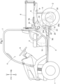
Fig. 1 is a left side view of a utility vehicle. -
Fig. 2 is a right side view of a utility vehicle. -
Fig. 3 is a diagram illustrating components such as a transmission case, an electric motor, an inverter, and a first battery as viewed from above. -
Fig. 4 is a diagram illustrating a transmission case, an electric motor, an inverter, and a first battery as viewed from the left side. -
Fig. 5 is a diagram illustrating a transmission case and an electric motor as viewed from backward. -
Fig. 6 is a diagram illustrating an inverter and an in-vehicle charger device as viewed from backward. - The description below deals with an example embodiment of the present invention with reference to drawings.
- The embodiment described below is a utility vehicle including a body. Drawings such as
Figs. 1 and2 show arrow F to indicate the forward side of the body, arrow B to indicate the backward side of the body, arrow U to indicate the upward side of the body, and arrow D to indicate the downward side of the body. Drawings such asFigs. 3 and5 show arrow L to indicate the left side of the body, which corresponds to the front side ofFig. 1 and the back side ofFig. 2 . Drawings such asFigs. 3 and5 show arrow R to indicate the right side of the body, which corresponds to the back side ofFig. 1 and the front side ofFig. 2 . The left-right direction of the body corresponds to the width direction of the body. -
Figs. 1 and2 each illustrate a utility vehicle for multiple purposes such as cargo transport and recreation. The utility vehicle includes a pair of left and right turnable and drivablefront wheels 1 as a travel device, a pair of left and right drivablerear wheels 2 as a travel device, and abody 3 provided with the front andrear wheels body 3 has a front portion provided with adriver section 4 for a driver to get in. Thedriver section 4 includes a driver'sseat 5, a passenger'sseat 5b next to the driver'sseat 5, asteering wheel 6 for turning thefront wheels 1, and a roll-over protective structure (ROPS) 7 that defines a driver space. The driver'sseat 5 and the passenger'sseat 5b are between thefront wheels 1 and therear wheels 2 in a plan view. The utility vehicle includes acargo box 8 backward of thedriver section 4 and abody frame 9 holding thecargo box 8 in such a manner that thecargo box 8 is swingable up and down about a coupling axis P for thecargo box 8 and thebody frame 9. Thecargo box 8 includes at opposite sides thereof twohandles 8a usable to swing thecargo box 8 up into a dumping orientation and down into a travel orientation. - As illustrated in
Figs. 1 to 3 , thebody 3 is provided with atransmission case 11, anelectric motor 12, aninverter 13, and afirst battery 14 to drive the front andrear wheels electric motor 12 includes anoutput pulley 15. Thetransmission case 11 includes aninput pulley 16. The utility vehicle includes anendless rotor 17 wound around the output andinput pulleys output pulley 15 is at a side portion of theelectric motor 12 which side portion is on the right side relative to the body. Theoutput pulley 15 is rotatable about an output axis of theelectric motor 12 as arotation axis 15a which output axis extends in the width direction of the body. Theinput pulley 16 is backward of theoutput pulley 15 relative to the body. Theinput pulley 16 is rotatable about an input axis of thetransmission case 11 as arotation axis 16a, which is parallel to therotation axis 15a. The utility vehicle includes acover 19 covering the output andinput pulleys Fig. 3 ). Theendless rotor 17 is an endless rotary belt for the present embodiment, but may alternatively be an endless rotary chain. - The
first battery 14 feeds its direct-current electric power to theinverter 13, which then converts it into alternating-current electric power. Theinverter 13 supplies the alternating-current electric power to theelectric motor 12 to drive theelectric motor 12. Theelectric motor 12 transmits its motive power from theoutput pulley 15 through theendless rotor 17 to theinput pulley 16 to be inputted into thetransmission case 11 and varied by a transmission (not illustrated in the drawings) in thetransmission case 11. The transmission outputs the varied motive power from a rear-wheel differential mechanism (not illustrated in the drawings) in thetransmission case 11 to therear wheels 2 and from a front output shaft 18 (seeFigs. 1 and4 ) at a front portion of thetransmission case 11 to thefront wheels 1. - The
transmission case 11 is, as illustrated inFigs. 1 to 3 , below thecargo box 8 and between therear wheels 2. The utility vehicle includes left and right suspension mechanisms 20 (seeFigs. 4 and5 ) extending from respective left and right lateral side portions of thetransmission case 11 to thebody frame 9. Thetransmission case 11 is held by thebody frame 9 with thesuspension mechanisms 20 in-between. - As illustrated in
Figs. 1 ,2 ,4 , and5 , thesuspension mechanisms 20 each include anupper arm 22, alower arm 23, and acushion device 24. The upper andlower arms driver section 4, extend backward from afront holder 9a of thebody frame 9, and are swingable up and down. Thecushion device 24 is below thecargo box 8, has an upper end coupled to thebody frame 9, and includes a shock absorber and a coil spring. The utility vehicle includes left andright coupler members 25 and left and right rear-wheel support members 26. Thetransmission case 11, as illustrated inFig. 5 , includes left and rightrear axle cases 11a protruding on respective left and right lateral sides toward the respectiverear wheels 2 and coupled to the respective rear-wheel support members 26 with use of therespective coupler members 25 to be held by the respective rear-wheel support members 26. The rear-wheel support members 26 are provided with respectiverear holders 26a. The upper andlower arms rear holders 26a and are coupled to thetransmission case 11 with use of therear holders 26a and the rear-wheel support members 26. Thecushion devices 24 have respective lower ends coupled to the respectiverear axle cases 11a of thetransmission case 11. - The
first battery 14 is, as illustrated inFigs. 1 to 3 , in the space under the driver'sseat 5 and the passenger's seat 5a, which is next to the driver'sseat 5. Thefirst battery 14 is oriented to have a first dimension L1 in the width direction of the body and a second dimension L2 in the front-back direction of the body, the first dimension L1 being larger than the second dimension L2. - As illustrated in
Figs. 1 to 3 , theelectric motor 12 is under thecargo box 8.
Theelectric motor 12 is, as illustrated inFigs. 1 ,3 , and4 , backward of thefirst battery 14 relative to the body, forward of thetransmission case 11 relative to the body, and between therear wheels 2. The utility vehicle includes afirst stay 27 extending from thetransmission case 11 and asecond stay 28 standing on a rear-wheel support member 26. As illustrated inFigs. 3 to 5 , theelectric motor 12 has a first end and a second end in the width direction of the body, the first and second ends being attached to the first and second stays 27 and 28, respectively. Theelectric motor 12 is held by the rear-wheel support members 26 with the first and second stays 27 and 28 and thetransmission case 11 in-between. - As illustrated in
Figs. 1 ,3 , and4 , theinverter 13 is backward of thefirst battery 14 relative to the body, forward of theelectric motor 12 relative to the body, and within the width of thefirst battery 14. The utility vehicle includes apartition plate 10 and aninverter holder 29 extending backward from thepartition plate 10. Theinverter 13 is, as illustrated inFig. 6 , attached to theinverter holder 29. Thepartition plate 10 is held by thebody frame 9 and separates the driver space of thedriver section 4 from the space under thecargo box 8. Theinverter 13 is held by thebody frame 9 with theinverter holder 29 and thepartition plate 10 in-between. - As illustrated in
Figs. 4 and6 , the utility vehicle includes a coolingfan 30 above theinverter 13. Theinverter holder 29 includes atop plate 29a holding afan case 31. The coolingfan 30 is rotatably held in thefan case 31. The coolingfan 30 is configured to draw air from outside thefan case 31 through anair intake opening 31a in thefan case 31 into thefan case 31 to generate cooling air and supply the cooling air through a throughhole 29b in thetop plate 29a to heat dissipatingfins 13a at an upper portion of theinverter 13 to cool theheat dissipating fins 13a. The coolingfan 30 cools theheat dissipating fins 13a to cool theinverter 13. - As illustrated in
Fig. 3 , the utility vehicle includes an in-vehicle charger device 32 backward of thefirst battery 14 relative to the body, forward of theelectric motor 12 relative to the body, and within the width of thefirst battery 14. The in-vehicle charger device 32 is, as illustrated inFigs. 3 and6 , next to theinverter 13 in the width direction of the body. The in-vehicle charger device 32 includes an in-vehicle charger 32a, a DC-to-DC converter 32b, and acharger case 32c containing the in-vehicle charger 32a and the DC-to-DC converter 32b. Thecharger case 32c includes a coolingfan 32d configured to blow cooling air to the in-vehicle charger 32a and the DC-to-DC converter 32b. - As illustrated in
Fig. 3 , the utility vehicle includes acharger port 33 opposite to theinverter 13 across the in-vehicle charger device 32 in the width direction of the body, forward of therear wheels 2 relative to the body, and laterally outward of the in-vehicle charger device 32 relative to the body. Thecharger port 33 is, as illustrated inFig. 1 , held by aholder 34a included in a rear-wheel fender 3. - Connecting a charger cord from a power source outside the body such as a charger stand to the
charger port 33 allows electric power to be supplied from the power source through thecharger port 33 to the in-vehicle charger 32a, which then charges thefirst battery 14. The in-vehicle charger 32a also supplies the electric power to the DC-to-DC converter 32b for voltage adjustment. The DC-to-DC converter 32b then supplies the resulting electric power to a second battery 35 (described below). - As illustrated in
Figs. 2 and3 , the utility vehicle includes asecond battery 35 opposite to the in-vehicle charger device 32 across theinverter 13 in the width direction of the body, forward of therear wheels 2 relative to the body, and laterally outward of theinverter 13. Thesecond battery 35 is configured to output electric power for operation control or the like which electric power has a voltage lower than that of electric power that thefirst battery 14 outputs. - As illustrated in
Figs. 3 to 6 , theelectric motor 12 is provided with aterminal section 36 on an outer surface, whereas theinverter 13 is provided with aninverter terminal section 37 on an outer surface. Theterminal section 36 includes a plurality ofmotor terminals 36a, whereas theinverter terminal section 37 includes a plurality ofinverter terminals 37a. Themotor terminals 36a are each connected to a predetermined one of theinverter terminals 37a with use of aharness 38, so that theelectric motor 12 is connected to theinverter 13. Theterminal section 36 for the present embodiment is an example including a terminal block on which themotor terminals 36a are arranged. Theterminal section 36 may alternatively omit the terminal block. - The
electric motor 12 is, as illustrated inFigs. 3 and4 , held by the rear-wheel support members 26 in such an orientation that theterminal section 36 is inclined on a portion of the outer surface which portion faces upward relative to the body. - Specifically, the
electric motor 12 is rotated about therotation axis 15a of theoutput pulley 15 as the output axis of theelectric motor 12. In response to theelectric motor 12 being rotated into such an orientation that the terminal section 36 (which is on a portion of the outer surface of theelectric motor 12 which portion faces upward relative to the body) is inclined to have a lowered back portion, theelectric motor 12 is attached to the first and second stays 27 and 28 in this orientation. This allows theelectric motor 12 to be held by the rear-wheel support members 26 in such an orientation that the terminal section 36 (which is on a portion of the outer surface which portion faces upward relative to the body) is inclined to have a lowered back portion. Theterminal section 36 is inclined to have a lowered back portion as viewed along therotation axis 15a of theoutput pulley 15,
which extends in the width direction of the body for the present embodiment. Theterminal section 36 is inclined to have a lowered back portion for the present embodiment, but may alternatively be inclined to have a lowered front portion in accordance with the rotation direction of theelectric motor 12. - As illustrated in
Figs. 1 and2 , theelectric motor 12 is under thecargo box 8. Swinging thecargo box 8 into the dumping orientation creates a large space available for maintenance work above theterminal section 36 to facilitate the work. The inclination of theterminal section 36 allows rain water or car washing water thereon to easily flow along and drop from theterminal section 36. - As illustrated in
Figs. 4 and6 , theinverter 13 is attached to theinverter holder 29 in such an orientation that theinverter terminal section 37 is on a portion of the outer surface which portion faces downward relative to the body. Theinverter 13 is, in other words, held by thebody frame 9 in the above orientation. This prevents rain water or car washing water falling from above onto theinverter 13 from easily reaching and wetting theinverter terminal section 37. -
- (1) The embodiment described above is an example in which the in-
vehicle charger device 32 includes both an in-vehicle charger 32a and a DC-to-DC converter 32b. The present invention is, however, not limited to such a configuration, and may alternatively be configured such that the in-vehicle charger 32a and the DC-to-DC converter 32b are not included in the in-vehicle charger device 32 and are separate from each other. - (2) The embodiment described above is an example in which the
front wheels 1 are drivable. Thefront wheels 1 may alternatively be not drivable. - (3) The embodiment described above is an example including an in-
vehicle charger device 32. The present invention may, however, omit the in-vehicle charger device 32. - (4) The embodiment described above is an example including a
second battery 35 opposite to the in-vehicle charger device 32 across theinverter 13 in the width direction of the body, forward of therear wheels 2 relative to the body, and laterally outward of theinverter 13. The present invention is, however, not limited to such a configuration, and may alternatively include asecond battery 35 at any other position. - (5) The embodiment described above is an example in which the
first battery 14 is oriented to have a first dimension in the width direction of the body and a second dimension in the front-back direction of the body, the first dimension being larger than the second dimension. The present invention is, however, not limited to such a configuration. Thefirst battery 14 may be oriented in any manner. - (6) The embodiment described above is an example in which the
electric motor 12 is oriented such that theterminal section 36 is inclined on a portion of the outer surface which portion faces upward relative to the body. Theelectric motor 12 may, however, be oriented in any manner, for instance, such that theterminal section 36 is horizontal on a portion of the outer surface which portion faces downward relative to the body. - (7) The embodiment described above is an example in which the
respective rotation axes - (8) The embodiment described above is an example in which the
cargo box 8 is movable into a dumping orientation. Thecargo box 8 may, however, alternatively be unmovable into a dumping orientation. - (9) The embodiment described above is an example in which the
inverter 13 is oriented such that theinverter terminal section 37 is on a portion of the outer surface which portion faces downward relative to the body. The present invention is, however, not limited to such a configuration. Theinverter terminal section 37 may be at any position, for instance, on a portion of the outer surface which portion faces upward relative to the body. - The present invention is applicable to any utility vehicle including a pair of left and right front wheels and a pair of left and right rear wheels.
-
- 1
- Front wheel
- 2
- Rear wheel
- 5
- Driver's seat
- 11
- Transmission case
- 12
- Electric motor
- 13
- Inverter
- 14
- First battery
- 32
- In-vehicle charger device
- 33
- Charger port
- 35
- Second battery
- L1
- Dimension in the width direction of the body
- L2
- Dimension in the front-back direction of the body
Claims (5)
- A utility vehicle, comprising:a pair of left and right front wheels (1);a pair of left and right rear wheels (2);a driver's seat (5) between the front wheels (1) and the rear wheels (2) in a plan view;an electric motor (12);a first battery (14);an inverter (13) configured to convert direct-current electric power from the first battery (14) into alternating-current electric power and supply the alternating-current electric power to the electric motor (12); anda transmission case (11) configured to receive motive power from the electric motor (12) and output the motive power to the rear wheels (2),the transmission case (11) being between the rear wheels (2),the electric motor (12) being forward of the transmission case (11) relative to a body of the utility vehicle and between the rear wheels (2),the first battery (14) being below the driver's seat (5),the inverter (13) being backward of the first battery (14) relative to the body, forward of the electric motor (12) relative to the body, and within a width of the first battery (14).
- The utility vehicle according to claim 1, further comprising:an in-vehicle charger device (32) configured to charge the first battery (14),wherein the in-vehicle charger device (32) is backward of the first battery (14) relative to the body, forward of the electric motor (12) relative to the body, within the width of the first battery (14), and next to the inverter (13) in a width direction of the body.
- The utility vehicle according to claim 2, further comprising:a charger port (33) configured to supply electric power from a power source outside the body to the in-vehicle charger device (32),wherein the charger port (33) is opposite to the inverter (13) across the in-vehicle charger device (32) in the width direction of the body, forward of the rear wheels (2) relative to the body, and laterally outward of the in-vehicle charger device (32) relative to the body.
- The utility vehicle according to any one of claims 1 to 3, wherein
the first battery (14) is oriented to have a first dimension (L1) in a width direction of the body and a second dimension (L2) in a front-back direction of the body, the first dimension (L1) being larger than the second dimension (L2). - The utility vehicle according to claim 2 or claim 3, or according to claim 4 taken in combination with claim 2, further comprising:a second battery (35) configured to output electric power with a voltage lower than a voltage of the direct-current electric power that the first battery (14) outputs,wherein the second battery (35) is opposite to the in-vehicle charger device (32) across the inverter (13) in the width direction of the body, forward of the rear wheels (2) relative to the body, and laterally outward of the inverter (13) relative to the body.
Applications Claiming Priority (1)
| Application Number | Priority Date | Filing Date | Title |
|---|---|---|---|
| JP2023132988A JP2025027833A (en) | 2023-08-17 | 2023-08-17 | Multi-purpose vehicles |
Publications (1)
| Publication Number | Publication Date |
|---|---|
| EP4512646A1 true EP4512646A1 (en) | 2025-02-26 |
Family
ID=92259064
Family Applications (1)
| Application Number | Title | Priority Date | Filing Date |
|---|---|---|---|
| EP24193188.0A Pending EP4512646A1 (en) | 2023-08-17 | 2024-08-06 | Utility vehicle |
Country Status (3)
| Country | Link |
|---|---|
| US (1) | US20250058651A1 (en) |
| EP (1) | EP4512646A1 (en) |
| JP (1) | JP2025027833A (en) |
Citations (4)
| Publication number | Priority date | Publication date | Assignee | Title |
|---|---|---|---|---|
| US20150122561A1 (en) * | 2013-11-07 | 2015-05-07 | Honda Motor Co., Ltd. | Electric vehicle |
| US20170174069A1 (en) * | 2015-12-21 | 2017-06-22 | Kubota Corporation | Work Vehicle |
| US20180264928A1 (en) * | 2017-03-16 | 2018-09-20 | Kubota Corporation | Work Vehicle |
| JP7050421B2 (en) | 2017-03-27 | 2022-04-08 | 株式会社クボタ | Multipurpose vehicle |
-
2023
- 2023-08-17 JP JP2023132988A patent/JP2025027833A/en active Pending
-
2024
- 2024-08-06 EP EP24193188.0A patent/EP4512646A1/en active Pending
- 2024-08-15 US US18/805,591 patent/US20250058651A1/en active Pending
Patent Citations (4)
| Publication number | Priority date | Publication date | Assignee | Title |
|---|---|---|---|---|
| US20150122561A1 (en) * | 2013-11-07 | 2015-05-07 | Honda Motor Co., Ltd. | Electric vehicle |
| US20170174069A1 (en) * | 2015-12-21 | 2017-06-22 | Kubota Corporation | Work Vehicle |
| US20180264928A1 (en) * | 2017-03-16 | 2018-09-20 | Kubota Corporation | Work Vehicle |
| JP7050421B2 (en) | 2017-03-27 | 2022-04-08 | 株式会社クボタ | Multipurpose vehicle |
Also Published As
| Publication number | Publication date |
|---|---|
| US20250058651A1 (en) | 2025-02-20 |
| JP2025027833A (en) | 2025-02-28 |
Similar Documents
| Publication | Publication Date | Title |
|---|---|---|
| US11623709B2 (en) | Drive assembly for an electric vehicle | |
| CN102730123B (en) | Electro-tricycle | |
| TWI247708B (en) | Electrically-driven vehicle | |
| US8668037B2 (en) | Saddle-ride-type electrically operated vehicle | |
| EP0608841B1 (en) | Electric vehicle with built-in charging unit | |
| JP5595227B2 (en) | Electric motorcycle | |
| US9211934B2 (en) | Electric vehicle | |
| CN104661854B (en) | Electric vehicle and set of cells | |
| JP2002503174A (en) | Oscillating arm power unit for single or double track electric motor driven vehicles | |
| US20150274013A1 (en) | Electric Vehicle | |
| CN102464071A (en) | Electric vehicle | |
| EP3436331B1 (en) | Vehicle having separable driver and propulsion modules | |
| JP3172952B2 (en) | Electric motorcycle | |
| EP2730453A2 (en) | Electrically driven vehicle | |
| JPWO2020165965A1 (en) | Saddle-mounted electric vehicle | |
| JP2024091942A (en) | Tractor | |
| CN111989260A (en) | Saddle-ride type electric vehicle | |
| EP4512646A1 (en) | Utility vehicle | |
| JPH05193370A (en) | Battery box for electric automobile | |
| WO2019123824A1 (en) | Battery housing | |
| EP4512647A1 (en) | Work vehicle | |
| EP4516548A1 (en) | Electric vehicle | |
| JP2763437B2 (en) | Electric car floor structure | |
| JPH05105144A (en) | Electric motorcycle | |
| JP2005199878A (en) | Vehicle structure |
Legal Events
| Date | Code | Title | Description |
|---|---|---|---|
| PUAI | Public reference made under article 153(3) epc to a published international application that has entered the european phase |
Free format text: ORIGINAL CODE: 0009012 |
|
| STAA | Information on the status of an ep patent application or granted ep patent |
Free format text: STATUS: REQUEST FOR EXAMINATION WAS MADE |
|
| 17P | Request for examination filed |
Effective date: 20240806 |
|
| AK | Designated contracting states |
Kind code of ref document: A1 Designated state(s): AL AT BE BG CH CY CZ DE DK EE ES FI FR GB GR HR HU IE IS IT LI LT LU LV MC ME MK MT NL NO PL PT RO RS SE SI SK SM TR |