US11623709B2 - Drive assembly for an electric vehicle - Google Patents
Drive assembly for an electric vehicle Download PDFInfo
- Publication number
- US11623709B2 US11623709B2 US17/560,907 US202117560907A US11623709B2 US 11623709 B2 US11623709 B2 US 11623709B2 US 202117560907 A US202117560907 A US 202117560907A US 11623709 B2 US11623709 B2 US 11623709B2
- Authority
- US
- United States
- Prior art keywords
- housing
- drive
- motor
- electric vehicle
- assembly
- Prior art date
- Legal status (The legal status is an assumption and is not a legal conclusion. Google has not performed a legal analysis and makes no representation as to the accuracy of the status listed.)
- Active
Links
Images


Classifications
-
- B—PERFORMING OPERATIONS; TRANSPORTING
- B62—LAND VEHICLES FOR TRAVELLING OTHERWISE THAN ON RAILS
- B62J—CYCLE SADDLES OR SEATS; AUXILIARY DEVICES OR ACCESSORIES SPECIALLY ADAPTED TO CYCLES AND NOT OTHERWISE PROVIDED FOR, e.g. ARTICLE CARRIERS OR CYCLE PROTECTORS
- B62J41/00—Arrangements of radiators, coolant hoses or pipes on cycles
-
- B—PERFORMING OPERATIONS; TRANSPORTING
- B62—LAND VEHICLES FOR TRAVELLING OTHERWISE THAN ON RAILS
- B62M—RIDER PROPULSION OF WHEELED VEHICLES OR SLEDGES; POWERED PROPULSION OF SLEDGES OR SINGLE-TRACK CYCLES; TRANSMISSIONS SPECIALLY ADAPTED FOR SUCH VEHICLES
- B62M7/00—Motorcycles characterised by position of motor or engine
- B62M7/02—Motorcycles characterised by position of motor or engine with engine between front and rear wheels
- B62M7/04—Motorcycles characterised by position of motor or engine with engine between front and rear wheels below the frame
-
- B—PERFORMING OPERATIONS; TRANSPORTING
- B62—LAND VEHICLES FOR TRAVELLING OTHERWISE THAN ON RAILS
- B62J—CYCLE SADDLES OR SEATS; AUXILIARY DEVICES OR ACCESSORIES SPECIALLY ADAPTED TO CYCLES AND NOT OTHERWISE PROVIDED FOR, e.g. ARTICLE CARRIERS OR CYCLE PROTECTORS
- B62J43/00—Arrangements of batteries
- B62J43/10—Arrangements of batteries for propulsion
- B62J43/16—Arrangements of batteries for propulsion on motorcycles or the like
-
- B—PERFORMING OPERATIONS; TRANSPORTING
- B62—LAND VEHICLES FOR TRAVELLING OTHERWISE THAN ON RAILS
- B62J—CYCLE SADDLES OR SEATS; AUXILIARY DEVICES OR ACCESSORIES SPECIALLY ADAPTED TO CYCLES AND NOT OTHERWISE PROVIDED FOR, e.g. ARTICLE CARRIERS OR CYCLE PROTECTORS
- B62J43/00—Arrangements of batteries
- B62J43/20—Arrangements of batteries characterised by the mounting
- B62J43/28—Arrangements of batteries characterised by the mounting hidden within the cycle frame
-
- B—PERFORMING OPERATIONS; TRANSPORTING
- B62—LAND VEHICLES FOR TRAVELLING OTHERWISE THAN ON RAILS
- B62J—CYCLE SADDLES OR SEATS; AUXILIARY DEVICES OR ACCESSORIES SPECIALLY ADAPTED TO CYCLES AND NOT OTHERWISE PROVIDED FOR, e.g. ARTICLE CARRIERS OR CYCLE PROTECTORS
- B62J45/00—Electrical equipment arrangements specially adapted for use as accessories on cycles, not otherwise provided for
-
- B—PERFORMING OPERATIONS; TRANSPORTING
- B62—LAND VEHICLES FOR TRAVELLING OTHERWISE THAN ON RAILS
- B62K—CYCLES; CYCLE FRAMES; CYCLE STEERING DEVICES; RIDER-OPERATED TERMINAL CONTROLS SPECIALLY ADAPTED FOR CYCLES; CYCLE AXLE SUSPENSIONS; CYCLE SIDE-CARS, FORECARS, OR THE LIKE
- B62K11/00—Motorcycles, engine-assisted cycles or motor scooters with one or two wheels
- B62K11/02—Frames
- B62K11/04—Frames characterised by the engine being between front and rear wheels
-
- B—PERFORMING OPERATIONS; TRANSPORTING
- B62—LAND VEHICLES FOR TRAVELLING OTHERWISE THAN ON RAILS
- B62M—RIDER PROPULSION OF WHEELED VEHICLES OR SLEDGES; POWERED PROPULSION OF SLEDGES OR SINGLE-TRACK CYCLES; TRANSMISSIONS SPECIALLY ADAPTED FOR SUCH VEHICLES
- B62M7/00—Motorcycles characterised by position of motor or engine
- B62M7/02—Motorcycles characterised by position of motor or engine with engine between front and rear wheels
-
- B—PERFORMING OPERATIONS; TRANSPORTING
- B62—LAND VEHICLES FOR TRAVELLING OTHERWISE THAN ON RAILS
- B62K—CYCLES; CYCLE FRAMES; CYCLE STEERING DEVICES; RIDER-OPERATED TERMINAL CONTROLS SPECIALLY ADAPTED FOR CYCLES; CYCLE AXLE SUSPENSIONS; CYCLE SIDE-CARS, FORECARS, OR THE LIKE
- B62K2204/00—Adaptations for driving cycles by electric motor
-
- Y—GENERAL TAGGING OF NEW TECHNOLOGICAL DEVELOPMENTS; GENERAL TAGGING OF CROSS-SECTIONAL TECHNOLOGIES SPANNING OVER SEVERAL SECTIONS OF THE IPC; TECHNICAL SUBJECTS COVERED BY FORMER USPC CROSS-REFERENCE ART COLLECTIONS [XRACs] AND DIGESTS
- Y02—TECHNOLOGIES OR APPLICATIONS FOR MITIGATION OR ADAPTATION AGAINST CLIMATE CHANGE
- Y02T—CLIMATE CHANGE MITIGATION TECHNOLOGIES RELATED TO TRANSPORTATION
- Y02T10/00—Road transport of goods or passengers
- Y02T10/60—Other road transportation technologies with climate change mitigation effect
- Y02T10/70—Energy storage systems for electromobility, e.g. batteries
Definitions
- the present disclosure relates to electric vehicles, and more specifically to drive assemblies for electric vehicles.
- an electric vehicle including a frame, a wheel coupled to the frame, and a battery assembly including a housing supported by the frame.
- the housing includes a top side and a bottom side opposite the top side.
- a drive assembly of the electric vehicle is at least partially enclosed within a drive housing unit.
- the drive assembly includes a motor configured to receive power from the battery assembly and a gear assembly configured to transmit torque from the motor to the wheel.
- the drive housing unit is positioned below the bottom side of the housing.
- an electric vehicle including a frame, a wheel coupled to the frame, a battery assembly with a housing supported by the frame, and a drive assembly at least partially enclosed within a drive housing unit.
- the drive assembly includes an inverter configured to convert the power supplied by the battery assembly from direct current to alternating current, a motor configured to receive power from the battery assembly via the inverter, and a gear assembly configured to transmit torque from the motor to the wheel.
- the electric vehicle also includes a coolant pump configured to circulate coolant to cool the drive assembly.
- the drive housing unit includes a gear housing at least partially enclosing the gear assembly, a motor housing at least partially enclosing the motor, and an inverter housing at least partially enclosing the inverter.
- the coolant pump is directly coupled to the inverter housing.
- a drive assembly for an electric vehicle including a drive housing unit with a motor housing, a gear housing, and an inverter housing, a motor at least partially enclosed within the motor housing, the motor having an output shaft defining a rotational axis, a gear assembly at least partially enclosed within the gear housing, the gear assembly including a pinion coupled to the output shaft and a drive gear meshed with the pinion, and an inverter at least partially enclosed within the inverter housing and configured to supply power to the motor.
- the gear housing and the inverter housing are positioned on opposite sides of the motor housing.
- FIG. 1 is a right side view of an electric vehicle including a drive assembly according to one embodiment of the disclosure.
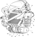
- FIG. 2 is a perspective view of a portion of the electric vehicle of FIG. 1 , illustrating the drive assembly and a battery assembly of the electric vehicle.
- FIG. 3 is a cross-sectional view of the drive assembly of FIG. 1 .
- FIG. 4 is a perspective view illustrating the drive assembly, the battery assembly, and a cooling assembly of the electric vehicle of FIG. 1 .
- FIG. 1 illustrates an electric vehicle in the form of a motorcycle 10 .
- the motorcycle 10 includes a frame 14 , a swing arm 18 pivotally coupled to a rear portion of the frame 14 , and a front fork 22 rotatably coupled to a front portion of the frame 14 at a steering head 26 .
- a rear wheel 30 is coupled to the swing arm 18
- a front wheel 34 is coupled to the front fork 22 .
- the rear wheel 30 and the front wheel 34 support the frame 14 for movement along the ground.
- the motorcycle 10 defines a longitudinal axis 36 that extends centrally through the motorcycle 10 along the length of the motorcycle 10 . In other words, the longitudinal axis 36 extends within a longitudinal mid-plane that bisects the motorcycle 10 along its length.
- a straddle seat 38 overlies at least a portion of the frame 14 for supporting at least one rider, and the motorcycle includes handlebars 42 coupled to the front fork 22 via the steering head 26 for steering the front wheel 34 .
- Various controls and indicators for operating the motorcycle 10 may be located on the handlebars 42 .
- the motorcycle 10 further includes a drive assembly 46 coupled to the rear wheel 30 to provide torque to the rear wheel 30 and thereby propel the motorcycle 10 .
- a battery assembly 50 is electrically coupled to the drive assembly 46 for powering the drive assembly 46 .
- the drive assembly 46 and battery assembly 50 are described herein in the context of the motorcycle 10 , it should be understood that the drive assembly 46 and the battery assembly 59 could be used on other electric vehicles, such as automobiles, all-terrain vehicles, and the like.
- the illustrated battery assembly 50 includes a battery housing (or simply a “housing”) 54 with an upper portion 58 and a lower portion 62 , each containing an array of rechargeable battery cells (e.g., lithium-based cells; not shown) that store and supply electrical power (i.e. voltage and current).
- the upper portion 58 and the lower portion 62 are coupled together by mechanical fasteners with a gap 66 between the two portions 58 , 62 .
- the gap 66 may allow air to flow between the upper and lower portions 58 , 62 to cool the battery assembly 50 .
- the housing 54 may be formed as a single piece, without distinct upper and lower portions.
- the housing 54 has a top side 70 A (on the upper portion 58 ), a bottom side 70 B (on the lower portion 62 ) opposite the top side 70 A, and first and second opposite lateral sides 70 C, 70 D extending between the top and bottom sides 70 A, 70 B.
- Rear and front sides 70 E, 70 F (defined with reference to a forward travel direction of the motorcycle 10 ) extend between the top and bottom sides 70 A, 70 B.
- the drive assembly 46 is coupled to the battery housing 54 and positioned below the bottom side 70 B of the battery housing 54 .
- the drive assembly 46 includes a motor 74 and a gear assembly 78 that transmits torque from an output shaft 82 of the motor 74 to a belt 86 that is coupled to the rear wheel 30 .
- the motor 74 is an AC induction motor
- the drive assembly 46 further includes an inverter 90 that converts DC power from the battery assembly 50 to AC power to be supplied to the motor 74 .
- the inverter 90 includes a circuit board 94 that connects switching electronics 98 (e.g., IGBTs, MOSFETS, or the like) in an inverter circuit.
- the circuit board 94 may also include other electronic components that control operation of the motor 74 .
- the motor 74 may be a DC motor, such that the inverter 90 may be omitted.
- the drive assembly 46 is housed within a drive housing unit 102 that includes a gear housing 106 , a motor housing 110 , and an inverter housing 114 , which are each aligned in series along a longitudinal axis 118 of the drive housing unit 102 .
- the longitudinal axis 118 may be parallel to and/or coaxial with a rotational axis of the output shaft 82 .
- the longitudinal axis 118 is also parallel to the longitudinal axis 36 of the motorcycle 10 ( FIG. 1 ).
- the drive housing unit 102 is positioned such that the longitudinal axis 118 is centered along the width W of the motorcycle 10 ( FIG. 2 ).
- the drive housing unit 102 includes a front end 122 and a rear end 126 , defined with respect to a forward travel direction of the motorcycle 10 (i.e. with reference to FIG. 1 , along the longitudinal axis 36 and to the right).
- the inverter housing 114 defines the front end 122
- the gear housing 106 defines the rear end 126 ( FIG. 3 ).
- the inverter housing 114 is disposed in front of the motor housing 110 along the longitudinal axis 118
- the gear housing 106 is disposed behind the motor housing 110 along the longitudinal axis 118 .
- the gear housing 106 at least partially encloses the gear assembly 78
- the motor housing 110 at least partially encloses the motor 74
- the inverter housing 114 at least partially encloses the inverter 90 .
- the gear housing 106 , the motor housing 110 , and the inverter housing 114 are formed as separate pieces and coupled together (e.g., via a plurality of mechanical fasteners, welding, threaded connections or any other suitable means), which may facilitate assembly of the drive assembly 46 .
- two or more of the gear housing 106 , the motor housing 110 , or the inverter housing 114 may be integrally formed together as a single piece.
- the gear housing 106 and the inverter housing 114 are coupled to opposite sides of the motor housing 110 such that the gear assembly 78 and the inverter 90 are positioned on opposite sides of the motor 74 .
- the illustrated gear assembly 78 includes a beveled pinion 130 coupled to an end of the output shaft 82 and a beveled drive gear 134 meshed with the pinion 130 .
- the drive gear 134 is supported on a drive shaft 138 for rotation about a drive axis 142 that is perpendicular to the longitudinal axis 118 and the output shaft 82 of the motor 78 .
- the drive axis 142 is positioned between the front and rear ends 122 , 126 of the drive housing unit 102 .
- the drive gear 134 has a greater number of teeth than the pinion 130 such that the drive shaft 138 rotates at a slower speed than the output shaft 82 of the motor 74 .
- a sprocket 146 is coupled to an end of the drive shaft 138 .
- the sprocket 146 drives the belt 86 (e.g., a toothed belt), which extends between the sprocket 146 and a driven sprocket (not shown) coupled to the rear wheel 30 .
- the belt 86 may be replaced with a chain.
- the drive shaft 138 may be directly coupled to the rear wheel 30 , or coupled to the rear wheel 30 via any other suitable torque transfer arrangement.
- the motorcycle further includes an onboard charger 150 to facilitate charging the battery cells of the battery assembly 50 and a cooling assembly 154 that removes heat from the charger 150 and the drive assembly 46 .
- the cooling assembly 154 includes a plurality of coolant lines 158 that fluidly couple the charger 150 , the drive assembly 46 , and a radiator 162 into a single cooling loop.
- the radiator 162 is coupled to the front side 70 F of the battery housing 54 .
- a coolant pump 166 is directly coupled to the front end 122 of the drive housing unit 102 (and thus, to the inverter housing 114 ). In other words, the coolant pump 166 is supported on the motorcycle 10 by the inverter housing 114 .
- the coolant pump 166 is operable to circulate coolant (e.g., a liquid coolant such as a glycol) through the cooling assembly 154 .
- the coolant pump 166 is enclosed by a cover 170 that is coupled to the front end 122 of the drive housing unit 102 ( FIG. 2 ).
- the cover 170 provides protection for the coolant pump 166 and preferably defines an aerodynamic outer shape.
- the lateral sides of the cover 170 are substantially flush with the sides of the inverter housing 114 .
- the cover 170 and the drive housing unit 102 define a single, cohesive assembly underneath the battery housing 54 .
Abstract
Description
Claims (6)
Priority Applications (2)
| Application Number | Priority Date | Filing Date | Title |
|---|---|---|---|
| US17/560,907 US11623709B2 (en) | 2018-07-27 | 2021-12-23 | Drive assembly for an electric vehicle |
| US18/179,151 US11858580B2 (en) | 2018-07-27 | 2023-03-06 | Drive assembly for an electric vehicle |
Applications Claiming Priority (3)
| Application Number | Priority Date | Filing Date | Title |
|---|---|---|---|
| US201862711216P | 2018-07-27 | 2018-07-27 | |
| US16/523,153 US11220307B2 (en) | 2018-07-27 | 2019-07-26 | Drive assembly for an electric vehicle |
| US17/560,907 US11623709B2 (en) | 2018-07-27 | 2021-12-23 | Drive assembly for an electric vehicle |
Related Parent Applications (1)
| Application Number | Title | Priority Date | Filing Date |
|---|---|---|---|
| US16/523,153 Division US11220307B2 (en) | 2018-07-27 | 2019-07-26 | Drive assembly for an electric vehicle |
Related Child Applications (1)
| Application Number | Title | Priority Date | Filing Date |
|---|---|---|---|
| US18/179,151 Division US11858580B2 (en) | 2018-07-27 | 2023-03-06 | Drive assembly for an electric vehicle |
Publications (2)
| Publication Number | Publication Date |
|---|---|
| US20220111924A1 US20220111924A1 (en) | 2022-04-14 |
| US11623709B2 true US11623709B2 (en) | 2023-04-11 |
Family
ID=69178832
Family Applications (3)
| Application Number | Title | Priority Date | Filing Date |
|---|---|---|---|
| US16/523,153 Active 2040-02-03 US11220307B2 (en) | 2018-07-27 | 2019-07-26 | Drive assembly for an electric vehicle |
| US17/560,907 Active US11623709B2 (en) | 2018-07-27 | 2021-12-23 | Drive assembly for an electric vehicle |
| US18/179,151 Active US11858580B2 (en) | 2018-07-27 | 2023-03-06 | Drive assembly for an electric vehicle |
Family Applications Before (1)
| Application Number | Title | Priority Date | Filing Date |
|---|---|---|---|
| US16/523,153 Active 2040-02-03 US11220307B2 (en) | 2018-07-27 | 2019-07-26 | Drive assembly for an electric vehicle |
Family Applications After (1)
| Application Number | Title | Priority Date | Filing Date |
|---|---|---|---|
| US18/179,151 Active US11858580B2 (en) | 2018-07-27 | 2023-03-06 | Drive assembly for an electric vehicle |
Country Status (1)
| Country | Link |
|---|---|
| US (3) | US11220307B2 (en) |
Cited By (2)
| Publication number | Priority date | Publication date | Assignee | Title |
|---|---|---|---|---|
| US20220009586A1 (en) * | 2020-07-10 | 2022-01-13 | Kawasaki Jukogyo Kabushiki Kaisha | Straddle vehicle |
| US11858580B2 (en) | 2018-07-27 | 2024-01-02 | Livewire Ev, Llc | Drive assembly for an electric vehicle |
Families Citing this family (3)
| Publication number | Priority date | Publication date | Assignee | Title |
|---|---|---|---|---|
| CN214524219U (en) * | 2020-11-10 | 2021-10-29 | 浙江春风动力股份有限公司 | Electric motorcycle capable of running stably |
| TWM607783U (en) * | 2020-11-18 | 2021-02-11 | 太宇工業股份有限公司 | Installation structure of bike motor component |
| WO2023073673A1 (en) * | 2021-10-29 | 2023-05-04 | Bombardier Recreational Products Inc. | Electric vehicle with a cooling arrangement |
Citations (39)
| Publication number | Priority date | Publication date | Assignee | Title |
|---|---|---|---|---|
| US5501292A (en) * | 1990-08-02 | 1996-03-26 | Honda Giken Kogyo Kabushiki Kaisha | Electrically operated vehicle |
| US5678646A (en) | 1994-12-02 | 1997-10-21 | Fichtel & Sachs Ag | Propulsion system and kit for hybrid motor vehicle |
| US6109383A (en) | 1997-09-14 | 2000-08-29 | Honda Giken Kogyo Kabushiki Kaisha | Power unit for motorcycle |
| US6158543A (en) | 1997-09-14 | 2000-12-12 | Honda Giken Kogyo Kabushiki Kaisha | Motorcycle with hybrid drive system |
| US6276481B1 (en) | 1997-09-14 | 2001-08-21 | Honda Giken Kogyo Kubushiki Kaisha | Power unit arrangement structure for motorcycle |
| JP2004210072A (en) | 2002-12-27 | 2004-07-29 | Yamaha Motor Co Ltd | Electric motorcycle |
| JP2004210073A (en) | 2002-12-27 | 2004-07-29 | Yamaha Motor Co Ltd | Electric motorcycle |
| US20110175467A1 (en) * | 2010-01-19 | 2011-07-21 | Brian Belton | Coolant system for electric motorcycle |
| US20120097463A1 (en) | 2010-10-25 | 2012-04-26 | Honda Motor Co., Ltd. | Saddle-ride type electric vehicle |
| US8485300B2 (en) | 2011-02-02 | 2013-07-16 | Honda Motor Co., Ltd. | Sports type, saddle type electric vehicle |
| US20130229072A1 (en) * | 2010-11-12 | 2013-09-05 | Kawasaki Jukogyo Kabushiki Kaisha | Cooling Structure for Cooling Electric Motor for Vehicle |
| US8602150B2 (en) | 2011-09-27 | 2013-12-10 | Honda Motor Co., Ltd. | Motor-driven vehicle |
| DE102012111962A1 (en) | 2012-12-07 | 2014-06-12 | Dr. Ing. H.C. F. Porsche Aktiengesellschaft | Final drive unit for motor car, has housing assembly containing heat exchanger unit that is operatively connected to electric machine and gear unit |
| US20140262568A1 (en) | 2011-10-28 | 2014-09-18 | Kawasaki Jukogyo Kabushiki Kaisha | Straddle Electric Vehicle |
| US8919481B2 (en) * | 2010-12-27 | 2014-12-30 | Kawasaki Jukogyo Kabushiki Kaisha | Saddle-type electric vehicle |
| US8973689B2 (en) | 2008-07-08 | 2015-03-10 | Ktm Sportmotorcycle Ag | Electrically operated vehicle with a rider saddle |
| US9030063B2 (en) | 2010-12-17 | 2015-05-12 | Tesla Motors, Inc. | Thermal management system for use with an integrated motor assembly |
| US9038756B2 (en) | 2011-05-18 | 2015-05-26 | S.M.R.E. S.P.A. | Propulsion system for a self-propelled vehicle with multiple electric drive units |
| US9290226B2 (en) | 2010-12-27 | 2016-03-22 | Kawasaki Jukogyo Kabushiki Kaisha | Oil passage structure for electric vehicle |
| US9308966B2 (en) | 2012-10-03 | 2016-04-12 | Kawasaki Jukogyo Kabushiki Kaisha | Saddle type electric vehicle |
| US9346421B2 (en) | 2013-11-06 | 2016-05-24 | Yamaha Hatsudoki Kabushiki Kaisha | Saddle-type electric vehicle |
| US20160226344A1 (en) | 2013-06-27 | 2016-08-04 | Kawasaki Jukogyo Kabushiki Kaisha | Electric vehicle |
| US20170040863A1 (en) | 2015-08-03 | 2017-02-09 | Zf Friedrichshafen Ag | Housing for a driving unit for a vehicle, driving unit for a vehicle and method for producing a driving unit for a vehicle |
| JP2017065319A (en) | 2015-09-28 | 2017-04-06 | ヤマハ発動機株式会社 | Saddle-riding type electric vehicle |
| US9669898B2 (en) | 2015-04-28 | 2017-06-06 | Yamaha Hatsudoki Kabushiki Kaisha | Electric vehicle |
| DE202017003396U1 (en) | 2017-06-28 | 2017-07-26 | Gkn Automotive Ltd. | Drive unit for a motor vehicle |
| US9821883B2 (en) | 2013-09-26 | 2017-11-21 | B Y M Ingenieros S.L. | Vehicle traction device and vehicle incorporating same |
| WO2019186749A1 (en) * | 2018-03-28 | 2019-10-03 | 本田技研工業株式会社 | Saddled electric vehicle |
| JP2020050074A (en) | 2018-09-26 | 2020-04-02 | スズキ株式会社 | Electric motorcycle |
| US10611425B2 (en) | 2013-11-06 | 2020-04-07 | Yamaha Hatsudoki Kabushiki Kaisha | Saddle-type electric vehicle |
| US20200172196A1 (en) * | 2017-09-11 | 2020-06-04 | Honda Motor Co., Ltd. | Electric motorcycle |
| US20200216138A1 (en) | 2019-01-07 | 2020-07-09 | Harley-Davidson Motor Company Group, LLC | Swingarm concentric motor drive for electric motorcycle |
| US20200398922A1 (en) * | 2018-03-29 | 2020-12-24 | Honda Motor Co., Ltd. | Straddle-type electric vehicle |
| US20210001943A1 (en) * | 2018-03-29 | 2021-01-07 | Honda Motor Co., Ltd. | Straddle-type electric vehicle |
| US20210001953A1 (en) * | 2018-03-29 | 2021-01-07 | Honda Motor Co., Ltd. | Straddle type electric vehicle |
| CN112810741A (en) * | 2020-11-10 | 2021-05-18 | 浙江春风动力股份有限公司 | High electric motorcycle car of security |
| US11220307B2 (en) | 2018-07-27 | 2022-01-11 | Harley-Davidson Motor Company Group, LLC | Drive assembly for an electric vehicle |
| EP3943376A1 (en) * | 2019-03-19 | 2022-01-26 | Honda Motor Co., Ltd. | Serial hybrid motorcycle |
| US20220348283A1 (en) * | 2020-11-18 | 2022-11-03 | Arctic Cat Inc. | Off-road vehicle |
Family Cites Families (6)
| Publication number | Priority date | Publication date | Assignee | Title |
|---|---|---|---|---|
| JP5505746B2 (en) * | 2012-09-07 | 2014-05-28 | 日立工機株式会社 | Electric tool |
| JP6661968B2 (en) * | 2015-10-27 | 2020-03-11 | スズキ株式会社 | Drainage structure of electric motorcycle |
| JP6639962B2 (en) * | 2016-03-09 | 2020-02-05 | 日立オートモティブシステムズ株式会社 | Electric drive device and electric power steering device |
| JP7149161B2 (en) * | 2018-10-30 | 2022-10-06 | 本田技研工業株式会社 | saddle type electric vehicle |
| JP7121633B2 (en) * | 2018-10-30 | 2022-08-18 | 本田技研工業株式会社 | saddle type electric vehicle |
| US20230226928A1 (en) * | 2021-09-17 | 2023-07-20 | Polaris Industries Inc. | Electric all-terrain vehicle |
-
2019
- 2019-07-26 US US16/523,153 patent/US11220307B2/en active Active
-
2021
- 2021-12-23 US US17/560,907 patent/US11623709B2/en active Active
-
2023
- 2023-03-06 US US18/179,151 patent/US11858580B2/en active Active
Patent Citations (46)
| Publication number | Priority date | Publication date | Assignee | Title |
|---|---|---|---|---|
| US5657830A (en) | 1990-08-02 | 1997-08-19 | Honda Giken Kogyo Kabushini Kaisha | Electrically operated saddle type vehicle |
| US5501292A (en) * | 1990-08-02 | 1996-03-26 | Honda Giken Kogyo Kabushiki Kaisha | Electrically operated vehicle |
| US5678646A (en) | 1994-12-02 | 1997-10-21 | Fichtel & Sachs Ag | Propulsion system and kit for hybrid motor vehicle |
| US6109383A (en) | 1997-09-14 | 2000-08-29 | Honda Giken Kogyo Kabushiki Kaisha | Power unit for motorcycle |
| US6158543A (en) | 1997-09-14 | 2000-12-12 | Honda Giken Kogyo Kabushiki Kaisha | Motorcycle with hybrid drive system |
| US6276481B1 (en) | 1997-09-14 | 2001-08-21 | Honda Giken Kogyo Kubushiki Kaisha | Power unit arrangement structure for motorcycle |
| JP2004210072A (en) | 2002-12-27 | 2004-07-29 | Yamaha Motor Co Ltd | Electric motorcycle |
| JP2004210073A (en) | 2002-12-27 | 2004-07-29 | Yamaha Motor Co Ltd | Electric motorcycle |
| US8973689B2 (en) | 2008-07-08 | 2015-03-10 | Ktm Sportmotorcycle Ag | Electrically operated vehicle with a rider saddle |
| US8212438B2 (en) | 2010-01-19 | 2012-07-03 | U.S. Alternate Energy, LLC | Coolant system for electric motorcycle |
| US20110175467A1 (en) * | 2010-01-19 | 2011-07-21 | Brian Belton | Coolant system for electric motorcycle |
| US20120097463A1 (en) | 2010-10-25 | 2012-04-26 | Honda Motor Co., Ltd. | Saddle-ride type electric vehicle |
| US20130229072A1 (en) * | 2010-11-12 | 2013-09-05 | Kawasaki Jukogyo Kabushiki Kaisha | Cooling Structure for Cooling Electric Motor for Vehicle |
| US20170291482A1 (en) | 2010-12-17 | 2017-10-12 | Tesla, Inc. | Integrated Electric Motor Assembly |
| US9030063B2 (en) | 2010-12-17 | 2015-05-12 | Tesla Motors, Inc. | Thermal management system for use with an integrated motor assembly |
| US9692277B2 (en) | 2010-12-17 | 2017-06-27 | Tesla, Inc. | Integrated electric motor assembly |
| US9290226B2 (en) | 2010-12-27 | 2016-03-22 | Kawasaki Jukogyo Kabushiki Kaisha | Oil passage structure for electric vehicle |
| US9308957B2 (en) | 2010-12-27 | 2016-04-12 | Kawasaki Jukogyo Kabushiki Kaisha | Saddle-type electric vehicle |
| US8919481B2 (en) * | 2010-12-27 | 2014-12-30 | Kawasaki Jukogyo Kabushiki Kaisha | Saddle-type electric vehicle |
| US8485300B2 (en) | 2011-02-02 | 2013-07-16 | Honda Motor Co., Ltd. | Sports type, saddle type electric vehicle |
| US9038756B2 (en) | 2011-05-18 | 2015-05-26 | S.M.R.E. S.P.A. | Propulsion system for a self-propelled vehicle with multiple electric drive units |
| US8602150B2 (en) | 2011-09-27 | 2013-12-10 | Honda Motor Co., Ltd. | Motor-driven vehicle |
| US20140262568A1 (en) | 2011-10-28 | 2014-09-18 | Kawasaki Jukogyo Kabushiki Kaisha | Straddle Electric Vehicle |
| US9308966B2 (en) | 2012-10-03 | 2016-04-12 | Kawasaki Jukogyo Kabushiki Kaisha | Saddle type electric vehicle |
| US9821882B2 (en) | 2012-10-03 | 2017-11-21 | Kawasaki Jukogyo Kabushiki Kaisha | Assembling method and assembling management method of electric vehicle |
| US9840306B2 (en) | 2012-10-03 | 2017-12-12 | Kawasaki Jukogyo Kabushiki Kaisha | Electric vehicle, and battery pack |
| DE102012111962A1 (en) | 2012-12-07 | 2014-06-12 | Dr. Ing. H.C. F. Porsche Aktiengesellschaft | Final drive unit for motor car, has housing assembly containing heat exchanger unit that is operatively connected to electric machine and gear unit |
| US20160226344A1 (en) | 2013-06-27 | 2016-08-04 | Kawasaki Jukogyo Kabushiki Kaisha | Electric vehicle |
| US9821883B2 (en) | 2013-09-26 | 2017-11-21 | B Y M Ingenieros S.L. | Vehicle traction device and vehicle incorporating same |
| US10611425B2 (en) | 2013-11-06 | 2020-04-07 | Yamaha Hatsudoki Kabushiki Kaisha | Saddle-type electric vehicle |
| US9346421B2 (en) | 2013-11-06 | 2016-05-24 | Yamaha Hatsudoki Kabushiki Kaisha | Saddle-type electric vehicle |
| US9669898B2 (en) | 2015-04-28 | 2017-06-06 | Yamaha Hatsudoki Kabushiki Kaisha | Electric vehicle |
| US20170040863A1 (en) | 2015-08-03 | 2017-02-09 | Zf Friedrichshafen Ag | Housing for a driving unit for a vehicle, driving unit for a vehicle and method for producing a driving unit for a vehicle |
| JP2017065319A (en) | 2015-09-28 | 2017-04-06 | ヤマハ発動機株式会社 | Saddle-riding type electric vehicle |
| DE202017003396U1 (en) | 2017-06-28 | 2017-07-26 | Gkn Automotive Ltd. | Drive unit for a motor vehicle |
| US20200172196A1 (en) * | 2017-09-11 | 2020-06-04 | Honda Motor Co., Ltd. | Electric motorcycle |
| WO2019186749A1 (en) * | 2018-03-28 | 2019-10-03 | 本田技研工業株式会社 | Saddled electric vehicle |
| US20200398922A1 (en) * | 2018-03-29 | 2020-12-24 | Honda Motor Co., Ltd. | Straddle-type electric vehicle |
| US20210001943A1 (en) * | 2018-03-29 | 2021-01-07 | Honda Motor Co., Ltd. | Straddle-type electric vehicle |
| US20210001953A1 (en) * | 2018-03-29 | 2021-01-07 | Honda Motor Co., Ltd. | Straddle type electric vehicle |
| US11220307B2 (en) | 2018-07-27 | 2022-01-11 | Harley-Davidson Motor Company Group, LLC | Drive assembly for an electric vehicle |
| JP2020050074A (en) | 2018-09-26 | 2020-04-02 | スズキ株式会社 | Electric motorcycle |
| US20200216138A1 (en) | 2019-01-07 | 2020-07-09 | Harley-Davidson Motor Company Group, LLC | Swingarm concentric motor drive for electric motorcycle |
| EP3943376A1 (en) * | 2019-03-19 | 2022-01-26 | Honda Motor Co., Ltd. | Serial hybrid motorcycle |
| CN112810741A (en) * | 2020-11-10 | 2021-05-18 | 浙江春风动力股份有限公司 | High electric motorcycle car of security |
| US20220348283A1 (en) * | 2020-11-18 | 2022-11-03 | Arctic Cat Inc. | Off-road vehicle |
Cited By (3)
| Publication number | Priority date | Publication date | Assignee | Title |
|---|---|---|---|---|
| US11858580B2 (en) | 2018-07-27 | 2024-01-02 | Livewire Ev, Llc | Drive assembly for an electric vehicle |
| US20220009586A1 (en) * | 2020-07-10 | 2022-01-13 | Kawasaki Jukogyo Kabushiki Kaisha | Straddle vehicle |
| US11858585B2 (en) * | 2020-07-10 | 2024-01-02 | Kawasaki Motors, Ltd. | Straddle vehicle |
Also Published As
| Publication number | Publication date |
|---|---|
| US20200031420A1 (en) | 2020-01-30 |
| US11858580B2 (en) | 2024-01-02 |
| US11220307B2 (en) | 2022-01-11 |
| US20230202605A1 (en) | 2023-06-29 |
| US20220111924A1 (en) | 2022-04-14 |
Similar Documents
| Publication | Publication Date | Title |
|---|---|---|
| US11623709B2 (en) | Drive assembly for an electric vehicle | |
| JP5595227B2 (en) | Electric motorcycle | |
| US9956883B2 (en) | Straddle electric vehicle | |
| US8485300B2 (en) | Sports type, saddle type electric vehicle | |
| EP0776818B1 (en) | Electrically assisted bicycle | |
| EP2657116B1 (en) | Electric motorcycle | |
| EP2799319B1 (en) | Saddle-type electric vehicle | |
| JP5479613B2 (en) | Straddle-type electric vehicle | |
| US20110226539A1 (en) | Vehicle with removable auxiliary power system | |
| JP5208095B2 (en) | Electric motorcycle | |
| KR101193165B1 (en) | Means of transport | |
| US11420709B2 (en) | Straddle type electric vehicle | |
| CA2566948A1 (en) | A bicycle having a removable power assist module | |
| US20220407320A1 (en) | Battery pack with integral charging port | |
| US10427540B2 (en) | Self propelled battery cooling system to extend the ride-range of an electric bike | |
| JPH06227474A (en) | Motor-driven bicycle | |
| US20040206557A1 (en) | Walk-behind self-propelled working machine | |
| CN111902339A (en) | Saddle-ride type electric vehicle | |
| JP2003002273A (en) | Battery device for motor vehicle | |
| NL8901981A (en) | ELECTRIC MOTOR AUXILIARY DRIVE FOR BICYCLES. | |
| CN111886178B (en) | Saddle-ride type electric vehicle | |
| JP5108636B2 (en) | snowblower | |
| JP3182706B2 (en) | Electric scooter | |
| JP4325857B2 (en) | Electric vehicle drive device | |
| JPH11266508A (en) | Motor-driven vehicle |
Legal Events
| Date | Code | Title | Description |
|---|---|---|---|
| AS | Assignment |
Owner name: HARLEY-DAVIDSON MOTOR COMPANY GROUP, LLC, WISCONSIN Free format text: ASSIGNMENT OF ASSIGNORS INTEREST;ASSIGNORS:AUNKST, DAVID ISAAC;REITINGER, SAMUEL NICHOLAS;KLUMPP, ERIC JAMES;AND OTHERS;SIGNING DATES FROM 20190718 TO 20190726;REEL/FRAME:058471/0643 |
|
| FEPP | Fee payment procedure |
Free format text: ENTITY STATUS SET TO UNDISCOUNTED (ORIGINAL EVENT CODE: BIG.); ENTITY STATUS OF PATENT OWNER: LARGE ENTITY |
|
| STPP | Information on status: patent application and granting procedure in general |
Free format text: DOCKETED NEW CASE - READY FOR EXAMINATION |
|
| STPP | Information on status: patent application and granting procedure in general |
Free format text: NON FINAL ACTION MAILED |
|
| STPP | Information on status: patent application and granting procedure in general |
Free format text: RESPONSE TO NON-FINAL OFFICE ACTION ENTERED AND FORWARDED TO EXAMINER |
|
| AS | Assignment |
Owner name: LIVEWIRE EV, LLC, WISCONSIN Free format text: ASSIGNMENT OF ASSIGNORS INTEREST;ASSIGNOR:HARLEY-DAVIDSON MOTOR COMPANY GROUP, LLC;REEL/FRAME:062126/0477 Effective date: 20221206 |
|
| STCF | Information on status: patent grant |
Free format text: PATENTED CASE |