EP4512331A2 - Systèmes et procédé d'activation d'électronique de capteur d'analyte - Google Patents
Systèmes et procédé d'activation d'électronique de capteur d'analyte Download PDFInfo
- Publication number
- EP4512331A2 EP4512331A2 EP24218650.0A EP24218650A EP4512331A2 EP 4512331 A2 EP4512331 A2 EP 4512331A2 EP 24218650 A EP24218650 A EP 24218650A EP 4512331 A2 EP4512331 A2 EP 4512331A2
- Authority
- EP
- European Patent Office
- Prior art keywords
- analyte sensor
- analyte
- sensor system
- state
- activation
- Prior art date
- Legal status (The legal status is an assumption and is not a legal conclusion. Google has not performed a legal analysis and makes no representation as to the accuracy of the status listed.)
- Pending
Links
Images











Classifications
-
- A—HUMAN NECESSITIES
- A61—MEDICAL OR VETERINARY SCIENCE; HYGIENE
- A61B—DIAGNOSIS; SURGERY; IDENTIFICATION
- A61B5/00—Measuring for diagnostic purposes; Identification of persons
- A61B5/0002—Remote monitoring of patients using telemetry, e.g. transmission of vital signals via a communication network
- A61B5/0031—Implanted circuitry
-
- A—HUMAN NECESSITIES
- A61—MEDICAL OR VETERINARY SCIENCE; HYGIENE
- A61B—DIAGNOSIS; SURGERY; IDENTIFICATION
- A61B5/00—Measuring for diagnostic purposes; Identification of persons
- A61B5/145—Measuring characteristics of blood in vivo, e.g. gas concentration or pH-value ; Measuring characteristics of body fluids or tissues, e.g. interstitial fluid or cerebral tissue
-
- A—HUMAN NECESSITIES
- A61—MEDICAL OR VETERINARY SCIENCE; HYGIENE
- A61B—DIAGNOSIS; SURGERY; IDENTIFICATION
- A61B5/00—Measuring for diagnostic purposes; Identification of persons
- A61B5/145—Measuring characteristics of blood in vivo, e.g. gas concentration or pH-value ; Measuring characteristics of body fluids or tissues, e.g. interstitial fluid or cerebral tissue
- A61B5/14503—Measuring characteristics of blood in vivo, e.g. gas concentration or pH-value ; Measuring characteristics of body fluids or tissues, e.g. interstitial fluid or cerebral tissue invasive, e.g. introduced into the body by a catheter or needle or using implanted sensors
-
- A—HUMAN NECESSITIES
- A61—MEDICAL OR VETERINARY SCIENCE; HYGIENE
- A61B—DIAGNOSIS; SURGERY; IDENTIFICATION
- A61B5/00—Measuring for diagnostic purposes; Identification of persons
- A61B5/145—Measuring characteristics of blood in vivo, e.g. gas concentration or pH-value ; Measuring characteristics of body fluids or tissues, e.g. interstitial fluid or cerebral tissue
- A61B5/14532—Measuring characteristics of blood in vivo, e.g. gas concentration or pH-value ; Measuring characteristics of body fluids or tissues, e.g. interstitial fluid or cerebral tissue for measuring glucose, e.g. by tissue impedance measurement
-
- A—HUMAN NECESSITIES
- A61—MEDICAL OR VETERINARY SCIENCE; HYGIENE
- A61B—DIAGNOSIS; SURGERY; IDENTIFICATION
- A61B5/00—Measuring for diagnostic purposes; Identification of persons
- A61B5/145—Measuring characteristics of blood in vivo, e.g. gas concentration or pH-value ; Measuring characteristics of body fluids or tissues, e.g. interstitial fluid or cerebral tissue
- A61B5/14546—Measuring characteristics of blood in vivo, e.g. gas concentration or pH-value ; Measuring characteristics of body fluids or tissues, e.g. interstitial fluid or cerebral tissue for measuring analytes not otherwise provided for, e.g. ions, cytochromes
-
- A—HUMAN NECESSITIES
- A61—MEDICAL OR VETERINARY SCIENCE; HYGIENE
- A61B—DIAGNOSIS; SURGERY; IDENTIFICATION
- A61B5/00—Measuring for diagnostic purposes; Identification of persons
- A61B5/145—Measuring characteristics of blood in vivo, e.g. gas concentration or pH-value ; Measuring characteristics of body fluids or tissues, e.g. interstitial fluid or cerebral tissue
- A61B5/1455—Measuring characteristics of blood in vivo, e.g. gas concentration or pH-value ; Measuring characteristics of body fluids or tissues, e.g. interstitial fluid or cerebral tissue using optical sensors, e.g. spectral photometrical oximeters
-
- A—HUMAN NECESSITIES
- A61—MEDICAL OR VETERINARY SCIENCE; HYGIENE
- A61B—DIAGNOSIS; SURGERY; IDENTIFICATION
- A61B5/00—Measuring for diagnostic purposes; Identification of persons
- A61B5/145—Measuring characteristics of blood in vivo, e.g. gas concentration or pH-value ; Measuring characteristics of body fluids or tissues, e.g. interstitial fluid or cerebral tissue
- A61B5/1495—Calibrating or testing of in-vivo probes
-
- A—HUMAN NECESSITIES
- A61—MEDICAL OR VETERINARY SCIENCE; HYGIENE
- A61B—DIAGNOSIS; SURGERY; IDENTIFICATION
- A61B5/00—Measuring for diagnostic purposes; Identification of persons
- A61B5/68—Arrangements of detecting, measuring or recording means, e.g. sensors, in relation to patient
- A61B5/6846—Arrangements of detecting, measuring or recording means, e.g. sensors, in relation to patient specially adapted to be brought in contact with an internal body part, i.e. invasive
- A61B5/6847—Arrangements of detecting, measuring or recording means, e.g. sensors, in relation to patient specially adapted to be brought in contact with an internal body part, i.e. invasive mounted on an invasive device
-
- A—HUMAN NECESSITIES
- A61—MEDICAL OR VETERINARY SCIENCE; HYGIENE
- A61B—DIAGNOSIS; SURGERY; IDENTIFICATION
- A61B5/00—Measuring for diagnostic purposes; Identification of persons
- A61B5/68—Arrangements of detecting, measuring or recording means, e.g. sensors, in relation to patient
- A61B5/6846—Arrangements of detecting, measuring or recording means, e.g. sensors, in relation to patient specially adapted to be brought in contact with an internal body part, i.e. invasive
- A61B5/6847—Arrangements of detecting, measuring or recording means, e.g. sensors, in relation to patient specially adapted to be brought in contact with an internal body part, i.e. invasive mounted on an invasive device
- A61B5/6848—Needles
- A61B5/6849—Needles in combination with a needle set
-
- H—ELECTRICITY
- H04—ELECTRIC COMMUNICATION TECHNIQUE
- H04Q—SELECTING
- H04Q9/00—Arrangements in telecontrol or telemetry systems for selectively calling a substation from a main station, in which substation desired apparatus is selected for applying a control signal thereto or for obtaining measured values therefrom
-
- A—HUMAN NECESSITIES
- A61—MEDICAL OR VETERINARY SCIENCE; HYGIENE
- A61B—DIAGNOSIS; SURGERY; IDENTIFICATION
- A61B2560/00—Constructional details of operational features of apparatus; Accessories for medical measuring apparatus
- A61B2560/02—Operational features
- A61B2560/0204—Operational features of power management
- A61B2560/0209—Operational features of power management adapted for power saving
-
- A—HUMAN NECESSITIES
- A61—MEDICAL OR VETERINARY SCIENCE; HYGIENE
- A61B—DIAGNOSIS; SURGERY; IDENTIFICATION
- A61B2560/00—Constructional details of operational features of apparatus; Accessories for medical measuring apparatus
- A61B2560/02—Operational features
- A61B2560/0223—Operational features of calibration, e.g. protocols for calibrating sensors
-
- A—HUMAN NECESSITIES
- A61—MEDICAL OR VETERINARY SCIENCE; HYGIENE
- A61B—DIAGNOSIS; SURGERY; IDENTIFICATION
- A61B2560/00—Constructional details of operational features of apparatus; Accessories for medical measuring apparatus
- A61B2560/02—Operational features
- A61B2560/0242—Operational features adapted to measure environmental factors, e.g. temperature, pollution
- A61B2560/0247—Operational features adapted to measure environmental factors, e.g. temperature, pollution for compensation or correction of the measured physiological value
- A61B2560/0252—Operational features adapted to measure environmental factors, e.g. temperature, pollution for compensation or correction of the measured physiological value using ambient temperature
-
- A—HUMAN NECESSITIES
- A61—MEDICAL OR VETERINARY SCIENCE; HYGIENE
- A61B—DIAGNOSIS; SURGERY; IDENTIFICATION
- A61B2560/00—Constructional details of operational features of apparatus; Accessories for medical measuring apparatus
- A61B2560/02—Operational features
- A61B2560/0242—Operational features adapted to measure environmental factors, e.g. temperature, pollution
- A61B2560/0247—Operational features adapted to measure environmental factors, e.g. temperature, pollution for compensation or correction of the measured physiological value
- A61B2560/0257—Operational features adapted to measure environmental factors, e.g. temperature, pollution for compensation or correction of the measured physiological value using atmospheric pressure
-
- A—HUMAN NECESSITIES
- A61—MEDICAL OR VETERINARY SCIENCE; HYGIENE
- A61B—DIAGNOSIS; SURGERY; IDENTIFICATION
- A61B2560/00—Constructional details of operational features of apparatus; Accessories for medical measuring apparatus
- A61B2560/02—Operational features
- A61B2560/0266—Operational features for monitoring or limiting apparatus function
-
- A—HUMAN NECESSITIES
- A61—MEDICAL OR VETERINARY SCIENCE; HYGIENE
- A61B—DIAGNOSIS; SURGERY; IDENTIFICATION
- A61B2560/00—Constructional details of operational features of apparatus; Accessories for medical measuring apparatus
- A61B2560/02—Operational features
- A61B2560/029—Operational features adapted for auto-initiation
-
- A—HUMAN NECESSITIES
- A61—MEDICAL OR VETERINARY SCIENCE; HYGIENE
- A61B—DIAGNOSIS; SURGERY; IDENTIFICATION
- A61B2562/00—Details of sensors; Constructional details of sensor housings or probes; Accessories for sensors
- A61B2562/02—Details of sensors specially adapted for in-vivo measurements
- A61B2562/0223—Magnetic field sensors
-
- A—HUMAN NECESSITIES
- A61—MEDICAL OR VETERINARY SCIENCE; HYGIENE
- A61B—DIAGNOSIS; SURGERY; IDENTIFICATION
- A61B2562/00—Details of sensors; Constructional details of sensor housings or probes; Accessories for sensors
- A61B2562/02—Details of sensors specially adapted for in-vivo measurements
- A61B2562/0257—Proximity sensors
-
- H—ELECTRICITY
- H04—ELECTRIC COMMUNICATION TECHNIQUE
- H04Q—SELECTING
- H04Q2209/00—Arrangements in telecontrol or telemetry systems
- H04Q2209/40—Arrangements in telecontrol or telemetry systems using a wireless architecture
-
- H—ELECTRICITY
- H04—ELECTRIC COMMUNICATION TECHNIQUE
- H04Q—SELECTING
- H04Q2209/00—Arrangements in telecontrol or telemetry systems
- H04Q2209/40—Arrangements in telecontrol or telemetry systems using a wireless architecture
- H04Q2209/43—Arrangements in telecontrol or telemetry systems using a wireless architecture using wireless personal area networks [WPAN], e.g. 802.15, 802.15.1, 802.15.4, Bluetooth® or Zigbee®
-
- H—ELECTRICITY
- H04—ELECTRIC COMMUNICATION TECHNIQUE
- H04Q—SELECTING
- H04Q2209/00—Arrangements in telecontrol or telemetry systems
- H04Q2209/80—Arrangements in the sub-station, i.e. sensing device
- H04Q2209/82—Arrangements in the sub-station, i.e. sensing device where the sensing device takes the initiative of sending data
- H04Q2209/823—Arrangements in the sub-station, i.e. sensing device where the sensing device takes the initiative of sending data where the data is sent when the measured values exceed a threshold, e.g. sending an alarm
-
- H—ELECTRICITY
- H04—ELECTRIC COMMUNICATION TECHNIQUE
- H04Q—SELECTING
- H04Q2209/00—Arrangements in telecontrol or telemetry systems
- H04Q2209/80—Arrangements in the sub-station, i.e. sensing device
- H04Q2209/88—Providing power supply at the sub-station
- H04Q2209/883—Providing power supply at the sub-station where the sensing device enters an active or inactive mode
-
- H—ELECTRICITY
- H04—ELECTRIC COMMUNICATION TECHNIQUE
- H04W—WIRELESS COMMUNICATION NETWORKS
- H04W76/00—Connection management
- H04W76/10—Connection setup
- H04W76/14—Direct-mode setup
Definitions
- the present developments relate generally to medical devices such as analyte sensors, and more particularly, but not by way of limitation, to systems, devices, and methods related to activating analyte sensor electronics on such medical devices.
- Diabetes mellitus is a disorder in which the pancreas cannot create sufficient insulin (Type I or insulin dependent) and/or in which insulin is not effective (Type 2 or non-insulin dependent).
- Type I or insulin dependent in which the pancreas cannot create sufficient insulin
- Type 2 or non-insulin dependent in which insulin is not effective
- a hypoglycemic reaction low blood sugar may be induced by an inadvertent overdose of insulin, or after a normal dose of insulin or glucose-lowering agent accompanied by extraordinary exercise or insufficient food intake.
- SMBG self-monitoring blood glucose
- non-invasive, transdermal (e.g., transcutaneous) and/or implantable electrochemical sensors are being developed for continuously detecting and/or quantifying blood glucose values.
- These devices generally transmit raw or minimally processed data for subsequent analysis at a remote device, which can include a display.
- the transmission to wireless display devices can be wireless.
- the remote device can then provide the user with information about the user's blood glucose levels. Because systems using such implantable sensors can provide more up to date information to users, they may reduce the risk of a user failing to regulate the user's blood glucose levels. Nevertheless, such systems typically still rely on the user to take action in order to regulate the user's blood glucose levels, for example, by making an injection.
- Such systems may typically include a glucose sensor implantable into a host and sensor electronics circuitry for processing and communicating glucose related information.
- the sensor and the sensor electronics circuitry are usually designed to be connected for the first time by a user or host after the sensor has been implanted into the user. Consequently, a pre-connected system can potentially reduce the amount of user interaction involved with deploying an analyte sensor system.
- an analyte sensor system in which an analyte sensor and analyte sensor electronics circuitry are configured to be electrically and mechanically coupled to each other before the analyte sensor is implanted into the user or host.
- the present disclosure relates generally to controlling activation of sensor electronics for the wireless communication of analyte data gathered using an analyte sensor system. More particularly, the present disclosure is directed to systems, methods, apparatuses, and devices, for using multiple techniques for controlling such activation in an analyte sensor system in which the analyte sensor is connected both electrically and mechanically to analyte sensor electronics circuitry before the analyte sensor is implanted in the host.
- primary signals may generally relate to signals pertaining to, correlating to, derived from, characterizing, and/or describing analyte information as derived from a host who is using the analyte sensor.
- secondary signals may generally relate to information gathered using the analyte sensor system, where the gathered information is information other than the primary signal(s) ( e.g ., the gathered information is not information used in a primary signal capacity to describe a relationship between the signal and the analyte information).
- the second condition is met if the information related to the analyte value indicates that the level of the analyte value in the host satisfies a threshold value.
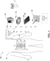
- Analyte sensor electronics module 12 may be in wireless communication (e.g. , directly or indirectly) with one or more of display devices 110, 120, 130, and 140.
- analyte sensor electronics module 12 may be in wireless communication (e.g. , directly or indirectly) with partner devices 136 and/or server system 134.
- display devices 110-140 may additionally or alternatively be in wireless communication ( e.g. , directly or indirectly) with partner devices 136 and/or server system 134.
- Various couplings shown in FIG. 1 can be facilitated with wireless access point 138, as also mentioned below.
- analyte sensor electronics module 12 includes electronic circuitry associated with measuring and processing analyte sensor data or information, including prospective algorithms associated with processing and/or calibration of the analyte sensor data/information.
- Analyte sensor electronics module 12 can be physically/mechanically connected to analyte sensor 10 and can be integral with (non-releasably attached to) or releasably attachable to analyte sensor 10.
- Analyte sensor electronics module 12 may also be electrically coupled to analyte sensor 10, such that the components may be electromechanically coupled to one another.
- Analyte sensor electronics module 12 may include hardware, firmware, and/or software that enables measurement and/or estimation of levels of the analyte in a host/user via analyte sensor 10 (e.g ., which may be/include a glucose sensor).
- analyte sensor electronics module 12 can include one or more of a potentiostat, a power source for providing power to analyte sensor 10, other components useful for signal processing and data storage, and a telemetry module for transmitting data from the sensor electronics module to one or more display devices.
- Electronics can be affixed to a printed circuit board (PCB) within analyte sensor system 8, or platform or the like, and can take a variety of forms.
- the electronics can take the form of an integrated circuit (IC), such as an Application-Specific Integrated Circuit (ASIC), a microcontroller, a processor, and/or a state machine.
- IC integrated circuit
- ASIC Application-Specific Integrated Circuit
- Analyte sensor electronics module 12 may include sensor electronics that are configured to process sensor information, such as sensor data, and generate transformed sensor data and displayable sensor information. Examples of systems and methods for processing sensor analyte data are described in more detail herein and in U.S. Patent Nos. 7,310,544 and 6,931,327 and U.S. Patent Publication Nos. 2005/0043598 , 2007/0032706 , 2007/0016381 , 2008/0033254 , 2005/0203360 , 2005/0154271 , 2005/0192557 , 2006/0222566 , 2007/0203966 and 2007/0208245 , all of which are incorporated herein by reference in their entireties.
- display devices 110, 120, 130, and/or 140 can be configured for displaying (and/or alarming) displayable sensor information that may be transmitted by sensor electronics module 12 ( e.g. , in a customized data package that is transmitted to the display devices based on their respective preferences).
- Each of display devices 110, 120, 130, or 140 can (respectively) include a display such as touchscreen display 112, 122, 132, /or 142 for displaying sensor information and/or analyte data to a user and/or receiving inputs from the user.
- a graphical user interface GUI may be presented to the user for such purposes.
- the display devices may include other types of user interfaces such as voice user interface instead of or in addition to a touchscreen display for communicating sensor information to the user of the display device and/or receiving user inputs.
- one, some, or all of display devices 110, 120, 130, 140 may be configured to display or otherwise communicate the sensor information as it is communicated from sensor electronics module 12 ( e.g. , in a data package that is transmitted to respective display devices), without any additional prospective processing required for calibration and/or real-time display of the sensor data.
- system 100 may also include wireless access point (WAP) 138 that may be used to couple one or more of analyte sensor system 8, the plurality display devices 110, 120, 130, 140 etc., server system 134, and medical device 136 to one another.
- WAP 138 may provide WiFi and/or cellular or other wireless connectivity within system 100.
- Near Field Communication (NFC) may also be used among devices of system 100 for exchanging data, as well as for performing specialized functions, e.g ., waking up or powering a device or causing the device (e.g ., analyte sensor electronics module 12 and/or a transmitter) to exit a lower power mode or otherwise change states and/or enter an operational mode.
- NFC Near Field Communication
- Server system 134 may be used to collect analyte data from analyte sensor system 8 and/or the plurality of display devices, for example, to perform analytics thereon, generate universal or individualized models for glucose levels and profiles, provide services or feedback, including from individuals or systems remotely monitoring the analyte data, and so on.
- Partner device(s) 136 can usually communicate ( e.g ., wirelessly) with analyte sensor system 8, including for authentication of partner device(s) 136 and/or analyte sensor system 8, as well as for the exchange of analyte data, medicament data, other data, and/or control signaling or the like.
- Partner devices 136 may include a passive device in example embodiments of the disclosure.
- partner device 136 may be an insulin pump for administering insulin to a user in response and/or according to an analyte level of the user as measured/approximated using analyte sensor system 8.
- an insulin pump for administering insulin to a user in response and/or according to an analyte level of the user as measured/approximated using analyte sensor system 8.
- One example reason for this is to provide the insulin pump a capability to suspend/activate/control insulin administration to the user based on the user's glucose value being below/above a threshold value.
- System 200 may be used in connection with implementing embodiments of the disclosed systems, methods, apparatuses, and/or devices, including, for example, aspects described above in connection with FIG. 1 .
- various below-described components of FIG. 2 may be used to provide wireless communication of analyte (e.g ., glucose) data, for example among/between analyte sensor system 308, display devices 310, partner devices 315, and/or one or more server systems 334, and so on.
- analyte e.g ., glucose
- system 200 may include analyte sensor system 308, one or more display devices 310, and/or one or more partner devices 315. Additionally, in the illustrated embodiment, system 200 includes server system 334, which can in turn includes server 334a coupled to processor 334c and storage 334b. Analyte sensor system 308 may be coupled to display devices 310, partner devices 315, and/or server system 334 via communication media 305. Some details of the processing, gathering, and exchanging of data, and/or executing actions (e.g ., providing medicaments or related instructions) by analyte sensor system 308, partner devices 315, and/or display device 310, etc., are provided below.
- Analyte sensor system 308, display devices 310, and/or partner devices 315 may exchange messaging (e.g. , control signaling) via communication media 305, and communication media 305 may also be used to deliver analyte data to display devices 310, partner devices 315, and/or server system 334.
- display devices 310 may include a variety of electronic computing devices, such as, for example, a smartphone, tablet, laptop, wearable device, etc.
- Display devices 310 may also include analyte display device 110 that may be customized for the display and conveyance of analyte data and related notifications etc.
- Partner devices 315 may include medical devices, such as an insulin pump or pen, connectable devices, such as a smart fridge or mirror, key fob, and other devices.
- communication media 305 may be based on one or more wireless communication protocols, such as for example Bluetooth, Bluetooth Low Energy (BLE), ZigBee, WiFi, IEEE 802.11 protocols, Infrared (IR), Radio Frequency (RF), 2G, 3G, 4G, 5G, etc., and/or wired protocols and media.
- wireless communication protocols such as for example Bluetooth, Bluetooth Low Energy (BLE), ZigBee, WiFi, IEEE 802.11 protocols, Infrared (IR), Radio Frequency (RF), 2G, 3G, 4G, 5G, etc., and/or wired protocols and media.
- communication media can be implemented as one or more communication links, including in some cases, separate links, between the components of system 200, whether or not such links are explicitly shown in FIG. 2 or referred to in connection therewith.
- analyte sensor system 308 may be coupled to display device 310 via a first link of communication media 305 using BLE, while display device 310 may be coupled to server system 334 by a second link of communication media 305 using a cellular communication protocol (e.g ., 4G LTE/ 5G and the like).
- a BLE signal may be temporarily attenuated to minimize data interceptions. For example, attenuation of a BLE signal through hardware or firmware design may occur temporarily during moments of data exchange ( e.g ., pairing).
- system 200 may be used to perform operations of various processes described herein and/or may be used to execute various operations and/or features described herein with regard to one or more disclosed systems and/or methods.
- system 200 may include single or multiple analyte sensor systems 308, communication media 305, and/or server systems 334.
- communication media 305 may be used to connect or communicatively couple analyte sensor system 308, display devices 310, partner devices 315, and/or server system 334 to one another or to a network.
- Communication media 305 may be implemented in a variety of forms.
- communication media 305 may include one or more of an Internet connection, such as a local area network (LAN), a person area network (PAN), a wide area network (WAN), a fiber optic network, internet over power lines, a hard-wired connection (e.g ., a bus), DSL, and the like, or any other kind of network connection or communicative coupling.
- LAN local area network
- PAN person area network
- WAN wide area network
- fiber optic network internet over power lines
- a hard-wired connection e.g ., a bus
- DSL and the like, or any other kind of network connection or communicative coupling.
- Communication media 305 may be implemented using any combination of routers, cables, modems, switches, fiber optics, wires, radio (e.g ., microwave/RF, AM, FM links etc.), and the like. Further, communication media 305 may be implemented using various wireless standards, such as Bluetooth ® , BLE, Wi-Fi, IEEE 802.11, 3GPP standards (e.g. , 2G GSM/GPRS/EDGE, 3G UMTS/CDMA2000, or 4G LTE/LTE-A/LTE-U, 5G, or subsequent generation), etc.
- 3GPP standards e.g. , 2G GSM/GPRS/EDGE, 3G UMTS/CDMA2000, or 4G LTE/LTE-A/LTE-U, 5G, or subsequent generation
- communication media 305 may be used to implement features of the present disclosure using as of yet undeveloped communications protocols that may be deployed in the future.
- server 334a may receive, collect, and/or monitor information, including analyte data, medicament data, and related information, from analyte sensor system 308, partner devices 315 and/or display devices 310, such as input responsive to the analyte data or medicament data, or input received in connection with an analyte monitoring application running on analyte sensor system 308 or display device 310, or a medicament delivery application running on display device 310 or partner device 315.
- server 334a may receive, collect, and/or monitor information from partner devices 315, such as, for example, information related to the provision of medicaments to a user and/or information regarding the operation of one or more partner devices 315.
- Server 334a may also receive, collect, and/or monitor information regarding a user of analyte sensor system 308, display devices 310, and/or partner devices 315.
- a database may be implemented in server system 334 that may pair user accounts to one or more analyte sensor systems 308 using communication media 305. Based on, for example, an expected lifetime of individual components or one or more groups of components of analyte sensor system 308, or analyte sensor system 308 as a whole, and/or based on diagnostic feedback received by analyte sensor system 308, server system 334 may be able to determine if a given analyte sensor system 308 or component or group(s) of components thereof is expired or passed its useful life.
- a user may receive an indication, notification, alert, or warning, for example, on display device 310 and/or through analyte sensor system 308, from server system 334, that analyte sensor system 308 or a component or group(s) of components thereof has expired or passed its useful life or will do so soon or within a given amount of time.
- a user may receive an indication, notification, alert, or warning on display device 310 from server system 334 about the expected lifetime of analyte sensor system 308 or a component or group(s) of components thereof.
- Server 334a may send/receive information to/from analyte sensor system 308, partner devices 315, and/or display devices 310 in real time, periodically, sporadically, or on an event-drive basis. Further, server 334a may implement cloud computing capabilities for analyte sensor system 308, partner devices 315, and/or display devices 310.
- analyte sensor 10 is an implantable glucose sensor, such as described with reference to U.S. Patent 6,001,067 and U.S. Patent Publication No. US-2005-0027463-A1 .
- analyte sensor 10 is a transcutaneous glucose sensor, such as described with reference to U.S. Patent Publication No. US-2006-0020187-A1 .
- analyte sensor 10 is configured to be implanted in a host vessel or extracorporeally, such as is described in U.S. Patent Publication No. US-2007-0027385-A1 , co-pending U.S. Patent Publication No. US-2008-0119703-A1 filed October 4, 2006 , U.S.
- analyte sensor 10 may be electromechanically coupled to analyte sensor electronics module 12 before analyte sensor system 8 is delivered to user and thus analyte sensor electronics module 12 is already coupled to analyte sensor 10 at the time of sensor implantation.
- this pre-coupling or pre-connection can lead to erroneous wakeups or activation from a lower power state, for example due to a signal generated by analyte sensor system 8 prior to sensor implantation ( e.g ., in situations of high humidity, static electricity, current leakage, or noise).
- analyte sensor 10 is not voltage biased by analyte sensor electronics module 12 before implantation.
- Operations that may cause changes to properties of analyte sensor 10 should generally be minimized before implantation. Accordingly, it may be preferred to avoid or at least reduce the occurrence of voltage biasing analyte sensor 10 before implantation. Applying voltage bias to analyte sensor 10 on a relatively long-term basis ( e.g ., during storage) may cause analyte sensor 10 to have a shorter than intended use life following implantation. This may be due to, for example, consumption of reference or enzyme capacity that may be contained on analyte sensor 10. Moreover, an analyte processing algorithm that may be used by analyte sensor system 8 may rely upon characterized performance values of analyte sensor 10.
- characterized performance values may include a baseline signal, analyte sensitivity, signal drift, lot performance metrics, curve fitting variables, tabular values, calibration codes, and/or additional factors that may be used as part of a signal processing algorithm in connection with determining analyte values.
- a relatively accurate estimate of analyte sensor 10 performance parameters and/or characteristics at the time of implantation into a user in order to enable accurate generation of analyte values.
- Significant durations e.g ., during shelf life
- applying a voltage bias across analyte sensor 10 may cause deviations from one or more predetermined performance metrics.
- the amount of power (e.g ., mW) used by the circuitry and/or other components (e.g ., within analyte sensor electronics module) that control activation of analyte sensor system 8 should generally be minimized, reduced, and/or considered in connection with making system level performance tradeoffs where possible.
- Power budgets may be at least somewhat limited by a battery capacity of analyte sensor system 8.
- analyte sensor system 8 may primarily remain in a lower power or mostly non-operational state prior to activation, and techniques used to control system activation and/or exit the lower power state may consume a small portion of available power.
- Detection of sensor implantation time by electronics module 12 can enable a higher reliability metric versus a reliance on the user providing notification of insertion/implantation time. For example, disconnection and/or implantation characteristics can distinguish a newly inserted analyte sensor 10 from an attempt of the user to restart an expired analyte sensor 10.
- analyte sensor system 8 may be placed in a state to establish and enter into communication with multiple devices based on being near to or at the time of implantation. For example, analyte sensor system 8 may be able to enter a pairing state within a relatively short time of implantation ( e.g.
- display devices e.g ., display devices 110, 120, 130, 140, partner device(s) 136, etc., referencing FIG. 1 by way of example
- a more accurate detection of analyte sensor 10 implantation time may also be used to trigger alternative connection profiles to encourage faster connection, for example, pairing, encryption, advertisement characteristics, etc. That is, for example, a more definitive wakeup event can be used to facilitate a more aggressive connection model as between analyte sensor system 8 and a device connectable thereto ( e.g ., sending advertisement packets at a faster rate or the like). This may enable faster connection establishment and may also provide the user with near real time feedback that analyte sensor system 8 is receiving a signal and is connected to the display device.
- An additional example of an advantage associated with accurate estimation of analyte sensor 10 implantation time that can be enabled by more robust wakeup techniques for analyte sensor 8 is improving error detection. Knowing the predicted profile and monitoring the signal measured using analyte sensor 10 from the time of implantation can enable recognition of deviations from expected characteristics of implantation in the signal profile. This can be enabled by knowledge of the implantation time of analyte sensor 10 as well as the ability to analyze the analyte signal at the time of implantation (for example, a signal that is associated with implantation is less likely to be missed due to analyte sensor system 8 being in a lower power state). The ability to recognize such deviations can trigger system safety or accuracy errors that may be hazardous for a user of analyte sensor system 8. For example, analyte sensors 10 that are physically damaged ( e.g. , membrane breaches, tears, manufacturing errors, etc.) may have different characteristic signals after implantation.
- physically damaged e.g. , membrane breaches, tears, manufacturing errors, etc.
- Yet another example of an advantage associated with accurate estimation of analyte sensor 10 implantation time is faster wakeup time for analyte sensor system 8, which may also enable improved error detection abilities. Risks of user variation in analyte sensor 10 implantation time may be reduced by using analyte sensor system 8 that is pre-connected and by detecting implantation time for analyte sensor 10 automatically or semi-automatically. Analyte sensor 10 that has been inserted into the incorrect tissue location (for example, not under the skin, or into muscle/fascia rather than a desired tissue layer) may have different characteristic signals than expected following insertion. Faster wakeup time may enable such issues to be detected more quickly following implantation, thus improving overall error detection performance associated with analyte sensor system 8.
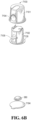
- FIG. 3A illustrates a perspective view of an on-skin sensor assembly 360 that may be used in connection with a preconnected analyte sensor system 8, in accordance with some embodiments.
- on-skin analyte sensor assembly 360 may include analyte sensor system 8, with reference by way of example to FIG. 1 .
- On-skin sensor assembly 360 may include an outer housing with a first, top portion 392 and a second, lower portion 394. In embodiments, the outer housing may include a clamshell design.
- On-skin sensor assembly 360 may include, for example, similar components as analyte sensor electronics module 140 described above in connection with FIG.
- a potentiostat for example, a potentiostat, a power source for providing power to analyte sensor 10, signal processing components, data storage components, and a communication module (e.g. , a telemetry module) for one-way or two-way data communication, a printed circuit board (PCB), an integrated circuit (IC), an Application-Specific Integrated Circuit (ASIC), a microcontroller, and/or a processor.
- the outer housing may feature a generally oblong shape.
- the outer housing may further include aperture 396 disposed substantially through a center portion of outer housing and adapted for sensor 338 and needle insertion through a bottom of on-skin sensor assembly 360.
- aperture 396 may be a channel or elongated slot.
- On-skin sensor assembly 360 may further include an adhesive patch 326 configured to secure on-skin sensor assembly 360 to skin of the host.
- adhesive patch 326 may include an adhesive suitable for skin adhesion, for example a pressure sensitive adhesive (e.g., acrylic, rubber-based, or other suitable type) bonded to a carrier substrate (e.g., spun lace polyester, polyurethane film, or other suitable type) for skin attachment, though any suitable type of adhesive is also contemplated.
- adhesive patch 396 may feature an aperture 398 aligned with aperture 396 such that sensor 338 may pass through a bottom of on-skin sensor assembly 360 and through adhesive patch 396.
- FIG. 3B illustrates a bottom perspective view of on-skin sensor assembly 360 of FIG. 3A.
- FIG. 3B further illustrates aperture 396 disposed substantially in a center portion of a bottom of on-skin sensor assembly 360, and aperture 398, both adapted for sensor 338 and needle insertion.
- FIG. 4 illustrates a cross-sectional view of on-skin sensor assembly 360 of FIGS. 3A and 3B .
- FIG. 4 illustrates first, top portion 392 and second, bottom portion 394 of the outer housing, adhesive patch 326, aperture 396 in the center portion of on-skin sensor assembly 360, aperture 398 in the center portion of adhesive patch 326, and sensor 338 passing through aperture 396.
- the electronics unit previously described in connection with FIG. 3A , may further include circuit board 404 and battery 402 configured to provide power to at least circuit board 404.
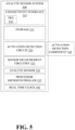
- analyte sensor system 308 may include analyte sensor 530 (e.g ., which may also be designated with the numeral 10 in FIG. 1 ) coupled to analyte sensor measurement circuitry 525 for processing and managing sensor data.
- Sensor measurement circuitry 525 may be coupled to processor/microprocessor 535 (e.g ., which may be part of item 12 in FIG. 1 ).
- processor 535 may perform part or all of the functions of sensor measurement circuitry 525 for obtaining and processing sensor measurement values from analyte sensor 530.
- Processor 535 may be further coupled to a radio unit or transceiver 510 (e.g ., which may be part of item 12 in FIG. 1 ) for sending sensor and other data and receiving requests and commands and other signaling from an external device, such as display device 310 (referencing FIG. 2 by way of example).
- Display device 310 may be used to display or otherwise provide the sensor data (or analyte data) or data derived therefrom to a user, server system 334, and/or partner device 315.
- Partner device 315 may utilize sensor data or a derivative data derived therefrom in the administration of medicaments (e.g ., insulin) and/or diabetes management guidance to the user.
- Analyte sensor system 308 may further include storage 515 ( e.g ., which may be part of item 12 in FIG. 1 ) and real time clock (RTC) 540 ( e.g ., which may be part of item 12 in FIG. 1 ), for storing and tracking sensor and other data.
- storage 515 e.g ., which may be part of item 12 in FIG. 1
- RTC real time clock
- Analyte sensor system 308 may also include activation detection circuit 520.
- Activation detection circuit 520 may optionally operate in conjunction with activation detection component 545.
- Activation detection component 545 may be integral to analyte sensor system 308, may be a component attachable thereto, and/or may be external thereto.
- Examples of activation detection circuit 520 may include one or more of (1) measurement circuitry that measures electrical characteristics associated with analyte sensor 10, such as capacitance or impedance, etc.; (2) proximity detection circuitry, which may use, for example, capacitive sensing, inductive sensing, magnetic detection, sonic detection, etc.; (3) temperature measurement circuitry; (4) accelerometer circuitry; (5) radio and/or antenna circuitry for NFC/RFID; (6) air pressure detection circuitry; (7) audio circuitry; (8) optical detection circuitry; (9) conductivity measurement circuitry; (10) switch detection circuitry; (11) strain detection circuitry; and so on.
- measurement circuitry that measures electrical characteristics associated with analyte sensor 10, such as capacitance or impedance, etc.
- proximity detection circuitry which may use, for example, capacitive sensing, inductive sensing, magnetic detection, sonic detection, etc.
- temperature measurement circuitry (4) accelerometer circuitry; (5) radio and/or antenna circuitry for NFC/RFID; (6) air pressure detection circuit
- Activation detection circuitry 520 and/or activation detection component 545 may also use or include logic circuitry adapted to execute stored instructions or computer code to perform functionalities as described herein with respect to detecting activation events/triggers and otherwise enabling activation of analyte sensor system 8 based upon triggering events/conditions and/or measurement of analyte values/characteristics/profiles. Additional details regarding activation detection circuit 520 and activation detection component 545 are discussed further elsewhere herein.
- Analyte sensor system 308 in example implementations gathers analyte data using sensor 530 and transmits the same or a derivative thereof to display device 310, partner device 315, and/or server system 334. Data points regarding analyte values may be gathered and transmitted over the life of sensor 530. New measurements and/or related information may be transmitted often enough for a remote device/individual to adequately monitor analyte (e.g., glucose) levels.
- analyte e.g., glucose
- embodiments of the present disclosure concern the timing for activating analyte sensor system 308 or causing the same to exit a lower power mode, particularly where analyte sensor system 308 is a pre-connected system.
- analyte sensor 10 may be mechanically and electrically coupled to analyte sensor electronics module 12 before analyte sensor 10 is implanted into a host.
- the user may delay implantation of analyte sensor 10 until after analyte sensor 10 is biased or after other secondary verification means are employed, thus wasting any power used to employ such secondary verification means (e.g ., NFC, accelerometer, impedance measurement, etc., as described in detail herein) and potentially decreasing the accuracy of analyte sensor 10 due to calibration drift that may result from applying bias.
- secondary verification means e.g ., NFC, accelerometer, impedance measurement, etc., as described in detail herein
- this time period may be preferred because it may be easier to detect activation events, for example, because typically detectable events that may occur (such as analyte sensor system 308 changing positions relative to the applicator) during this time period may occur over a longer period of time, relative to, e.g ., detectable events that may be associated with analyte sensor system 308 deployment.
- This time period may also be preferred for detecting activation related indicators because it is usually closer in time to implantation of analyte sensor 10, thus helping reduce user-created false wakeups, such as, for example, that may occur when the user unboxes analyte sensor system 308 but then chooses not to implant analyte sensor 10.
- events that may occur in the applicator for analyte sensor system 308 may serve as more effective markers for estimating implantation time and/or activating analyte sensor system 308 or causing the same to exit a lower power state.
- Another time period that may be used for causing analyte sensor system 308 to exit a lower power state may be after the implantation of analyte sensor 10.
- Mechanical, electrical, and/or electromechanical (or other nonmechanical) means may be employed for triggering an activation of analyte sensor system 308.
- analyte sensor 10 itself may be used for triggering analyte sensor system 308 to wake up or exit a lower power state.
- delay can impact analyte sensor system 308 from executing other operations that it is capable of performing, such as, pairing with display devices 310, partner devices 315, etc., communicating analyte values to display devices 310, partner devices 315, etc., and the like.
- Such signals may be quantified in units such as pA (current flow), pW (power), or counts (digital values converted from an analog value such as a voltage, a current, a power and/or a time), and these values can be used for purposes of triggering analyte sensor system 308 to exit a lower power state.
- pA current flow
- pW power
- counts digital values converted from an analog value such as a voltage, a current, a power and/or a time
- a benchmark threshold of current units may be used for triggering a wake-up or activation of analyte sensor system 308.
- basing such triggering on a predetermined current unit (e.g ., counts) threshold can sometimes result in false wakeups or missed wakeups.
- analyte sensor system 308 may be caused to wake up or enter an operational mode in situations when it should remain in lower power state or storage mode.
- analyte sensor system 308 use a benchmark threshold for current measurements for analyte sensor 10 (e.g. , of approximately X counts, where X may be, for example, 9,000 counts) that may generally be measured over a certain amount of time in units of seconds or minutes ( e.g., 300 seconds or 5 minutes).
- the benchmarked threshold can be monitored in the context of a persistent condition, where the benchmarked threshold may be configured to be met or exceeded for a predetermined amount of time before an activation is triggered, thus helping ensure that analyte sensor system 308 should indeed wake up.
- the persistent condition can include consistent-frequency current measurements (e.g ., including digital counts in some cases) over a subset of a time duration used for measuring current for activation purposes. For example, this can ensure that the benchmark threshold is not reached based on an undesired anomaly, such as a short duration spike of current (or, e.g., digital counts) within the time period for monitoring current through analyte sensor 10 for purposes of activating analyte sensor system 308.
- consistent-frequency current measurements e.g ., including digital counts in some cases
- this can ensure that the benchmark threshold is not reached based on an undesired anomaly, such as a short duration spike of current (or, e.g., digital counts) within the time period for monitoring current through analyte sensor 10 for purposes of activating analyte sensor system 308.
- the measured current (e.g ., number of received counts) for analyte sensor 10 may be compared with a benchmark threshold (e.g ., X counts, which can be approximately 9000 counts).
- a benchmark threshold e.g ., X counts, which can be approximately 9000 counts.
- processor 535 which may be part of or operation in conjunction with activation detection circuit 520, can initiate an operational mode of analyte sensor system 308.
- analyte sensor system 308 may begin receiving/obtaining sensor information from analyte sensor 530.
- estimated analyte value data is then transmitted to one or more display devices 110, etc.
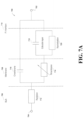
- FIG. 7A is a schematic diagram of equivalent circuit model 700 for analyte sensor 10, in accordance with embodiments of the present disclosure.
- Sensor circuit model 700 can represent electrical properties of analyte sensor 10, such as an embodiment of a continuous glucose sensor.
- Circuit 700 includes first terminal 704 ( e.g., which may be a working electrode) and second terminal 702 ( e.g ., which may be a reference electrode).
- first terminal 704 e.g., which may be a working electrode
- second terminal 702 e.g ., which may be a reference electrode
- Rsolution 712 representative of a resistance of bulk 706 between first and second terminals 704 and 702.
- Bulk 706 can be a liquid (e.g ., interstitial fluid) or other medium in which analyte sensor 10 is placed, such as a buffer solution in the example of a bench laboratory study, or, in the example of the use as a subcutaneously placed analyte sensor 10, bulk 706 can be representative of the subcutaneous tissue environment between first and second terminals 704 and 702.
- a liquid e.g ., interstitial fluid
- bulk 706 can be representative of the subcutaneous tissue environment between first and second terminals 704 and 702.
- Cmembrane 716 representative of a capacitance of membrane 708 of analyte sensor 10, and Rmembrane 714, representative of a resistance of membrane 708 of analyte sensor 10.
- a parallel network of Cdouble layer 718 and Rpolarization 720 are operatively connected to Rinembrane 714.
- the parallel network of Cdouble layer 718 and Rpolarization 720 is representative of the reactions occurring at the surface of a platinum interface of first terminal 704.
- Cdouble layer 718 is representative of the charge that is built up when a working electrode (e.g., platinum) is in bulk 706 and Rpolarization 720 is the polarization resistance of the electrochemical reactions that may occur at working electrode interface 710.
- a non-analyte signal is generated using analyte sensor 10 and used for purposes of activating analyte sensor system 308 and/or causing analyte sensor system 308 to exit a lower power mode.
- One such non-analyte signal includes a signal that may represent certain electrical, physical, or other properties of analyte sensor 10.
- a stimulus signal may be used to determine certain properties of analyte sensor 10.
- a capacitance of analyte sensor 10 may be detected and used to trigger analyte sensor system 308 to activate and/or exit a lower power state.
- the capacitance of analyte sensor 10 may change when analyte sensor 10 membrane is hydrated or placed within an environment having a higher or lower humidity.
- Activation detection circuit 520 may include a circuit that responds to analyte sensor 10 capacitance and drives a time varying signal (e.g ., a square wave, voltage step, alternating current signal, or the like) through analyte sensor 10, detecting how that signal may be affected by analyte sensor 10 capacitance.
- analyte sensor 10 responds to the driving signal can be indicative of a capacitance associated with analyte sensor 10. For example, a minimum level of capacitance for analyte sensor 10 could be required to detect a threshold response to the driving signal. Accordingly, analyte sensor system 308 can use activation detection circuit 520 to measure a metric indicative of capacitance for analyte sensor 10 and, based on that capacitance metric, a determination can be made as to whether or not analyte sensor 10 has been implanted in a host. It should be appreciated that the measured capacitance can include one or more of Cmembrane 716, Cdouble layer 718 (referencing FIG.
- a driving signal could be passed through analyte sensor 10 between first and second terminals 702 and 704, where the driving signal may then be affected by Cmembrane 716, Cdouble layer 718, and other capacitances that may be associated with analyte sensor 10 and used to approximate those capacitances and/or a total amount of capacitance that may load analyte sensor 10.
- Impedance is another characteristic of analyte sensor 10 that may be detected and used to trigger analyte sensor system 308 to activate and/or exit a lower power state.
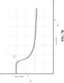
- FIG. 7B illustrates example plot 726 of analyte sensor 10 impedance value (e.g ., in units of Ohms) 722 versus time from implantation 724 ( e.g ., in units of seconds).
- impedance value 722 of analyte sensor 10 after a certain amount of time following implantation ( e.g., 30 seconds), may begin to decrease.
- impedance value 722 largely stabilizes following a certain amount of time after implantation of analyte sensor 10.
- the change e.g ., decrease in impedance value 722, or a rate of change of the impedance value, or the like
- the change e.g ., decrease in impedance value 722, or a rate of change of the impedance value, or the like
- the change e.g
- a resulting current between terminals of analyte sensor 10 can be detected using activation detection circuit 520.
- the relationship between the applied voltage and resulting current can then be used to calculate an impedance for analyte sensor 10.
- the voltage that may develop over the capacitor may represent a measure of the impedance of analyte sensor 10 (e.g., as measured based on a voltage divider that may be arranged between an impedance of analyte sensor 10 and a known impedance).
- a voltage comparator circuit set at a desired level, insertion of analyte sensor 10 can be determined and used to trigger analyte sensor system 308 to exit a lower power state.
- Such circuits may be designed and integrated into a chip that can be operated at very low power ( e.g., less than 1 uA during lower power state).
- the chip and/or circuit can then send a control signal to processor 535 to cause analyte sensor system 308 to exit the lower power state.
- Components such as one or more switches and one or more current limiting resistors may be used in circuit 800 to provide a more accurately detectable analyte sensor 530 implantation event and thus more robust control for activating analyte sensor system 308 or causing analyte sensor system 308 to exit a lower power mode.
- a switch can be used to couple a first terminal of analyte sensor 530 to a potentiostat or other measurement device or circuit.
- a detection circuit may in certain examples include an amplifying element (such as, e.g., a comparator, low-noise amplifier, other amplifier, or the like) and/or other circuitry.
- the switch that may be used to couple the first terminal of analyte sensor 530 to the measurement device can be opened or put in a high impedance state, to decouple the first terminal of analyte sensor 530 from the measurement device/potentiostat, while a second switch can couple the first and second terminals of analyte sensor 530 together, for example, through a current limiting resistor, to at least substantially discharge analyte sensor 530 capacitance.
- the voltage potential that may be present across analyte sensor 530 can be set, reset, and/or zeroed out.
- this activation detection mechanism can more reliably distinguish between multiple electrical characteristics that may be measured for analyte sensor 530, where some such electrical characteristics may be indicative of a hydration state of analyte sensor 530 and other such characteristics may merely indicate a high humidity environment, and activate analyte sensor system 308 more appropriately, reliably, or accurately.
- circuit 800 may include analyte sensor 808 and measurement device 810 (e.g., a potentiostat).
- measurement device 810 e.g., a potentiostat
- analyte sensor 808 may be similar, substantially similar, or the same as, for example, analyte sensor 530 referenced in connection with FIG. 5 .
- analyte sensor 808 may be at least partially different than analyte sensor 530, depending upon the contexts and/or applications in which analyte sensors 530 and/or 808 may be used.
- circuit 800 may include capacitive element 834, and optionally includes resistive element 832. Circuit 800 may also include detection circuit 802, which may in some cases be, use, or include an amplifying element (e.g ., a comparator), for example. Additionally, circuit 800 may include one or more of reference voltage 804, reference voltage 818, and driver circuit 806, which may be, for example, a clock-based driver. It should be appreciated that one or more of reference voltages 804 and 818 may be substituted for other reference signals. It should also be appreciated that driver circuit 806 may be driven by signals other than clock signals.
- detection circuit 802 may in some cases be, use, or include an amplifying element (e.g ., a comparator), for example.
- circuit 800 may include one or more of reference voltage 804, reference voltage 818, and driver circuit 806, which may be, for example, a clock-based driver. It should be appreciated that one or more of reference voltages 804 and 818 may be substituted for other reference signals. It should also be appreciated that driver circuit 8
- current based activation techniques for analyte sensor system 308 may be performed using a circuit similar to circuit 800 shown in FIG. 8A .
- switch element 812 may not be present in circuit 800, or may be bypassed or short circuited, for example.
- Switch element 814 may also not be present or may be effectively removed from circuit 800, and/or may be placed in a high impedance or open circuit state.
- resistive element 832 may also be effectively removed from circuit 800. It should be appreciated that other means may be employed to effectively remove and/or bypass resistive element 832.
- implantation of analyte sensor 808 may still be determined/monitored based upon detecting certain (e.g., sufficient) current flow(s) between first and second terminals 828 and 830 of analyte sensor 808.
- Measurement device 810 may apply a potential across terminals 828 and 830 of analyte sensor 830 (e.g., a substantially continual voltage).
- terminal 828 may be placed at a higher potential than terminal 830, such that current flow through analyte sensor 808 may be sourced through terminal 824 of measurement device 810 ( e.g., a potentiostat in some cases).
- terminal 826 of measurement device 810 and terminal 830 of analyte sensor 808 may be coupled to one another and/or to current-to-voltage conversion circuitry.
- the current-to-voltage conversion circuitry may include capacitive element 834 that may be coupled at a first end to terminals 826 and 830, and at a second end to reference voltage 818 (e.g., ground).
- the first end of capacitive element may also be coupled to switching element 816.
- Switching element 816 may be driven by driving circuit 806, which may be, include, and/or use a clock-based or other signal type driver. Switching element 816 may in this manner cause terminals 826 and 830 to be alternatively coupled to and decoupled from reference voltage 818.
- Terminals 826 and 830 may be coupled to and decoupled from reference voltage 818 periodically according to a configurable, programmable, adaptable, and/or variable interval/frequency (e.g ., 10 Hz).
- driver circuit 806 may cause the coupling/decoupling of terminals 826 and 830 to/from reference voltage 818 to be aperiodic, asynchronous, and/or event-driven.
- terminals 826 and 830 may be disconnected or decoupled from reference voltage 818 ( e.g ., may be floating).
- reference voltage 818 e.g ., may be floating
- analyte sensor 808 may not be as accurately modeled by a substantially or purely resistive load. Instead, it may be more accurate to electrically model analyte sensor 808 using a more complex passive circuit model, for example, as is shown in FIG. 7A , that includes both capacitors and resistors and that may include other elements.
- circuit 800 may operate in a different fashion when terminals 828 and 830 of analyte sensor 808 are first connected within circuit 800. In some cases, the difference may be significant or appreciable.
- the amplitude may decrease rapidly in some cases, and may decrease substantially, for example, according to an exponential decay that may be associated with a resistive/capacitive (RC) characteristic of the electrical equivalent model for analyte sensor 808 illustrated by way of example in FIG. 7A .
- RC resistive/capacitive
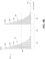
- FIG. 8B which is discussed in further detail below.
- the pulses that may be included in waveform 870 exhibit an exponential decay during time period 845. It should be appreciated, however, that if the resistive model is used for analyte sensor 808, this decay may not be present, and instead, the pulses of waveform 870 may be relatively constant in amplitude.
- the operation of the current-to-voltage circuit may remain significantly affected by the presence of the charged capacitor. For example, if a more complex electrical model is used, the amplitude of the residual voltage pulses that may be measurable across capacitive element 834 for a given steady state current may be meaningfully lower than the equivalent steady state current that would be present under the resistive load electrical model for analyte sensor 808. Moreover, the proportional difference in magnitude of the corresponding voltage waveforms for the two different currents may no longer be sufficiently differentiated by detection circuit 802 under normal circumstances. For example, detection circuit 802 may not be capable of as accurately detecting threshold crossings etc., due to the relatively small or diminished difference in the steady state voltage pulse amplitude that may result when the electrical model of FIG. 7A is employed.
- circuit 800 may produce steady state currents that may not result in voltage pulse waveforms of sufficient magnitude for detection or differentiation by detection circuit 802.
- This example configuration of circuit 800 may thus not be as conducive to accurate and robust activation of analyte sensor system 308.
- there may be only a single or small number of opportunities to generate a sufficient voltage waveform that can be more easily/accurately/reliably detected by detection circuit 802.
- the initial relatively large voltage pulse that may result from initial inrush of charging current may provide only a single detection event.
- circuit 800 may not have another sufficiently detectable opportunity to detect/assess implantation of analyte sensor 808.
- circuit 800 may include switch elements 812 and 814.
- Switch elements 812, 814, and 816 may be implemented using electrical components, including discrete or integrated components, such as transistors or other passive/active devices (e.g., FET switches, etc.).
- switch elements 812 and 814 may be complementary, such that when one switch element is closed, the other may be open and vice versa.
- Switch elements 812 and 814 may be controlled using a clock or other signal driver, and in some cases this clock may be derived from the clock or other source/driving signal used for driver circuit 806.
- switch elements 812 and 814 may be controlled by a clock or other source with a lower frequency than the clock or other source that may be used for driver circuit 806.
- the (e.g., clock) frequency for switch elements 812 and 814 may be a fraction of the (e.g., clock) frequency for switching element 816, where the value of the fraction that may be used can be configurable, programmable, adaptable, and/or variable. Examples/options for the fraction may include, in some cases, 1/10, 1/20, /40, 1/80 etc.
- switch elements 812 and 814 may change state every 10, 20, 40, or 80 cycles of the clock for switch element 816.
- Other ratios and relationships that can be set up with respect to driver circuit 806 and the control of switch elements 812 and 814 will be appreciated upon studying the present disclosure.
- Output 836 of detection circuit 802 may be coupled to, for example, processor 535 of analyte sensor system 308, such that output 836 may be used for activation or triggering of analyte sensor system 308.
- Circuit 800 may be implemented within or in conjunction with activation detection circuit 520. When circuit 800 is implemented as or as part of activation detection circuit 520, output 836 may be coupled to processor 535, such that when signaled to do so, processor 535 may be used to cause or trigger analyte sensor system 308 to wake up or exit a lower power state.
- analyte sensor 808 may include first and second terminals 828 and 830.
- Detection circuit 802 may include reference terminal 820 and input terminal 822.
- Measurement device 810 may include first terminal 824 and second terminal 826.
- circuit 800 may be used to control activation of analyte sensor system 308.
- Detection circuit 802 may indicate whether a signal at input terminal 822 meets one or more conditions.
- the condition may be or include one or more threshold voltages that may be set using reference voltage(s) 804 applied to reference terminal(s) 820 of detection circuit 802.
- the voltage(s) at input terminal(s) 822 may be indicative of a current that may flow between first and second terminals 828 and 830 of analyte sensor 808 (e.g., as described above, circuit elements of circuit 800, including capacitive element 834, may be used to effectively convert current through analyte sensor 808 to a voltage).
- the condition(s) may be, use, and/or include a threshold that is programmable, adaptable, variable, and/or configurable, etc.
- condition(s) can be configured such that the condition(s) may be met when the voltage(s) of one or more signals provided at input terminal 822 is (are) indicative of current that may flow between first and second terminals 828 and 830 of analyte sensor 808 when analyte sensor 808 is implanted in a host or under other conditions.
- output(s) 836 of detection circuit 802 may be used to trigger analyte sensor system 308 to exit a lower power state by indicating that this signal(s) at input terminal 822 satisfies(y) the condition(s) (e.g., depending on the level(s) of the output signal(s) 836).
- output(s) 836 of detection circuit 802 may include binary levels, multiple discrete levels, and/or continuous or substantially continuous or analog values that may be used to trigger activation of analyte sensor system 308 into one or more triggered or active states.
- the state that analyte sensor system 308 enters may depend upon characteristics (e.g., levels, trends, etc.) of output 836.
- the condition(s) may be configured to be met when a certain number of voltage pulses satisfy (e.g., meet or exceed) the threshold(s), or when a certain number of sets of voltage pulses exceed the threshold(s), as will be discussed further in connection with FIG. 8B .
- Switch element 812 may be used to couple or decouple first terminal 828 of analyte sensor 808 to/from first terminal 824 of measurement device 810 (e.g. , a potentiostat).
- Switch element 814 may be used to couple or decouple first terminal 828 of analyte sensor 808 to/from input terminal 822 of detection circuit 802 (optionally through resistive element 832).
- Input terminal 822 of detection circuit 802 may be coupled to second terminal 830 of analyte sensor 808 and to second terminal 826 of measurement device 810.
- switch element 812 may be closed or placed in a conductive state, coupling first terminal 828 of analyte sensor 808 to first terminal 824 of measurement device 810.
- Switch element 814 may be open or placed in a high impedance state at this time, decoupling input terminal 822 of detection circuit 802 from first terminal 828 of analyte sensor 808.
- measurement device 810 may be used in connection with gathering information that may be used to calculate the level of the analyte in the host.
- a voltage waveform generated using circuit 800 (e.g., as alluded to above), and specifically using charging current that may flow through a capacitance of analyte sensor 808, may be fed to the terminal 822 and monitored and compared to reference voltage 804 using detection circuit 802 (e.g., which may be or include an amplifying element and/or a comparator or other circuit).
- detection circuit 802 e.g., which may be or include an amplifying element and/or a comparator or other circuit.
- switch element 812 may be open or set to a high impedance state, thus decoupling first terminal 828 of analyte sensor 808 from first terminal 824 of measurement device 810.
- Switch element 814 may be closed or set to a low impedance or conductive state at this time, thus coupling second terminal 830 of analyte sensor 808 to first terminal 828 of analyte sensor 808 (optionally through resistive element 832 in some cases). This may reduce or possibly eliminate the voltage potential present across analyte sensor 808 and at least substantially discharge the stored charge of a capacitance of analyte sensor 808 ( see , e.g. , FIG.
- resistive element 832 may optionally be used to limit current that may flow through switch elements 814 and/or 816 when switch elements 814 and/or 816 is/are closed or placed in a conductive or low impedance state.
- Capacitive element 834 may be coupled between input terminal 822 of detection circuit 802 (which is shown in this example as being coupled to second terminal 830 of analyte sensor 808) and voltage reference 818 (e.g., ground).
- Switch element 816 may be driven by, or otherwise obtain as an input, a signal from driver circuit 806 (e.g., a clock or other signal), such that switch element 816 may periodically couple input terminal 822 of detection circuit 802 to reference 818. Where, for example, voltage reference 818 is ground, this may at least substantially discharge capacitive element 834, as further referenced/discussed in connection with FIG. 8B .
- capacitive element 834 in conjunction with driver circuit 806 and/or switch element 816 may be used to implement a current-to-voltage circuit.
- the current-to-voltage circuit may be operable to convert current that may flow through analyte sensor 808 into a voltage (e.g., waveform) that can be measured or otherwise characterized using detection circuit 802 in connection with determining whether a threshold/condition has been met or satisfied, as referenced above, and further in connection with activating and/or triggering analyte sensor system 308 to change states.
- Conductive jumper 612 can be located at least partially between two electrical connections of analyte sensor system 308.
- Conductive jumper 612 can include two springs 608 coupled by conductive link 616, where conductive jumper 612 and springs 608 are supported by housing 614 of analyte sensor system 308.
- springs 608 may be deflected such that springs 608 electrically connect to one another through physical contact, thus forming a bridge that may be used to trigger activation of analyte sensor system 308.
- activation detection circuit 520 and/or activation detection component 545 may include a non-conductive separation tab-based sensor or switch that may be used to cause analyte sensor system 308 to exit a lower power state in various embodiments.
- a non-conductive material may be placed between spring-loaded electrical contacts. The removal of the nonconductive material may then cause the spring-loaded electrical contacts to form a physical/electrical connection, electrically coupling the contacts.
- Certain of the above-described electromechanical detection techniques may be employed in connection with embodiments that utilize a user step for purposes or activating analyte sensor system 308.
- the user may push a button, pull a tab, take a step that forms or breaks a bridge, etc. to trigger activation of analyte sensor system 308.
- the user can be instructed to take such a step before or after analyte sensor 10 implantation, or within a certain time window thereof.
- a signal from an external device or a signal generated based on user input may be used to trigger activation of analyte sensor system 308.
- the display of an electronic device e.g ., smartphone, proprietary analyte display device, or smartwatch, referencing FIG. 1
- the display of an electronic device can be used to direct light (e.g ., from a flash or screen of the device, as mentioned above), audio (e.g ., frequency), or vibration to analyte sensor system 308.
- Activation detection circuit 520 and/or activation detection component 545 can then be used to detect such external stimuli via, for example, a photodiode, microphone, or piezoelectric sensor, and in response thereto to trigger activation.
- a user may tap a pattern on analyte sensor 308 that can be detected using a microphone and/or an accelerometer and used to trigger activation.
- An accelerometer of analyte sensor system 308 may also use pattern detection, for example, of the human gait/walk, for activation purposes. That is, if analyte sensor system 308 detects that it is moving in accordance with the human gait, it can be inferred that implantation of analyte sensor 530 has occurred.
- One or more embodiments as disclosed herein may utilize impedance measurements and/or current counts indicative of a current flowing through an analyte sensor (e.g., analyte sensor 530 of FIG. 5 ) to determine when the analyte sensor has been deployed into a skin of a host and, therefore, when at least a portion of sensor electronics (e.g., analyte sensor system 308 of FIG. 5 by way of example and not limitation) should exit a lower power "storage” or “sleep” mode and “wake up” to begin processing one or more samples of a sensor signal and/or sensor data.
- an analyte sensor e.g., analyte sensor 530 of FIG. 5
- sensor electronics e.g., analyte sensor system 308 of FIG. 5 by way of example and not limitation
- Some embodiments can utilize a clocked processor-based controller (e.g., processor/microcontroller 535 of FIG. 5 ) to provide one or more pulsed voltages across the terminals of analyte sensor 530, perform consecutive current count and/or impedance measurements or determinations of analyte sensor 530 based on a response to the pulsed voltages, average and analyze the current count and/or impedance measurements.
- a clocked processor-based controller e.g., processor/microcontroller 535 of FIG. 5
- Such pulsed voltages may have durations on the order of milliseconds and accurate estimation of an average current flowing through analyte sensor 530 and/or an impedance of analyte sensor 530 can require many current count samples (e.g., 125) to be averaged over an extended period of time (e.g., 10-12 seconds). While such controller-based solutions have been shown to work, constantly powering clocked processor-based controller 535 during the sample acquisition process requires a significant
- One solution is to offload such a controller-based method for measuring and/or determining current counts indicative of a current flowing through analyte sensor 530 to a hardware-based state machine (e.g., state machine 1430 of FIG. 14 ), which consumes considerably less power than clocked processor-based controller 535.
- a hardware-based state machine e.g., state machine 1430 of FIG. 14
- clocked processor-based controller 535 can set up one or more parameters of state machine 1430 and then enter a lower power "sleep" state, rather than performing all actions by itself, staying “awake,” and undesirably draining the battery.
- state machine 1430 can be implemented utilizing one or more registers (e.g., parameter register 1436 of FIG. 14 ), one or more counters (e.g., counter 1434 of FIG. 14 ) and/or one or more memories (e.g., a portion of storage 515 of FIG. 5 ).
- registers e.g., parameter register 1436 of FIG. 14
- counters e.g., counter 1434 of FIG. 14
- memories e.g., a portion of storage 515 of FIG. 5 .
- state machine 1430 can be tasked with controlling the application of one or more pulsed voltages across the terminals of analyte sensor 530, controlling the measurement of a current induced in analyte sensor 530 by the one or more pulsed voltages, and storing one or more data samples (e.g., digital counts) based on the current response. Controller 535 may then wake up, responsive to an interrupt or wake signal from state machine 1430, to process the one or more stored data samples, the number of which may be variable based on the particular implementation. Such a solution can reduce the overall power consumption of analyte sensor system 308, in some cases by 50-60% or more, compared to the above-described data acquisition process utilizing only clocked processor-based controller 535.
- State machine 1430 can be utilized to capture, at least partly process, and/or store current counts corresponding to a current flowing through the analyte sensor during a "storage” mode, when the controller is largely “sleeping,” or during a “run” mode when continuous analyte (e.g., glucose) measurements are being measured, determined, estimated and/or otherwise processed.
- continuous analyte e.g., glucose
- an analog front end (AFE) of the analyte sensor system e.g., at least a portion of sensor measurement circuitry 525 of FIG. 5
- can wake periodically e.g., every 64 seconds
- one or more current count measurements indicative of a current flowing through analyte sensor 530 to determine whether analyte sensor 530 has been inserted into the skin of the host, indicating that a transition from "storage” mode to a "run” mode or “wake” state is appropriate.
- This process can also be utilized to differentiate current count values indicative of analyte sensor 530 being properly inserted into the skin from current count values indicative of analyte sensor 530 being subjected to environmental conditions (e.g., high relative humidity) that may falsely indicate sensor insertion into the skin of the host. Accordingly, this process can help to avoid false wakeup of controller 535 due to, e.g., high relative humidity conditions, as detailed below. For example, when analyte sensor 530 is inserted into the skin of the host, a relatively moderate to lower impedance (e.g., several hundred k ⁇ ) of analyte sensor 530 will result in a certain observed current flow through analyte sensor 530.
- environmental conditions e.g., high relative humidity
- State-machine 1430 described herein can allow differentiation between these two states such that these environmental conditions (e.g., sufficiently high relative humidity) do not inadvertently trigger a false wakeup of controller 535, thereby further reducing power consumption due to unnecessary and inappropriate waking of controller 535.
- environmental conditions e.g., sufficiently high relative humidity
- FIG. 12 illustrates a state diagram 1200 related to, e.g., state machine 1430 of FIG. 14 , at least for determining one or more current counts indicative of a current flowing through analyte sensor 530, in accordance with some embodiments.
- State diagram 1200 illustrates 7 potential states: 5 potential delay states (e.g., delay 1 WE_L state 1206, delay 2 WE_L state 1212, delay 1 WE_H state 1216, delay 2 WE_H state 1224, and idle state 1228) and two potential sampling states (e.g., pre-count sampling state 1208 and pulse count sampling state 1220). While operation of state machine 1430 is described in more detail below in connection with FIGs. 13-15 , a brief overview here can be helpful in understanding the function and utility of the different states.
- 5 potential delay states e.g., delay 1 WE_L state 1206, delay 2 WE_L state 1212, delay 1 WE_H state 1216, delay 2 WE_H state 1224, and idle state 1228
- two potential sampling states
- a known voltage may be applied across the terminals of analyte sensor 530 and Ohm's Law can be used to determine the impedance based on the current generated by that known voltage.
- the current generated by the known voltage can have components that are not necessarily directly attributable to, e.g., a membrane impedance of analyte sensor 530, but to other environmental factors. Accordingly, an impedance determined based on a single current or current count.
- the interval between measurement of the first and second current count values is sufficiently small, subtracting the first current count value from the second current count value can reliably remove much of the effect of environmental factors from the measurements and an accurate membrane impedance value for analyte sensor 530 can be obtained therefrom based on an understanding that such impedance would be inversely related to the difference between the first and second current counts, since with such sufficiently small intervals between measurements, the effects of such environmental factors can be assumed to have a similar effect on both the first and the second current counts.
- the initial instantaneous currents induced through analyte sensor 530 will not be indicative of the sensor's steady-state impedance, as determined according to Ohm's Law, due to the RC characteristics of analyte sensor 530, for example as previously described in connection with FIG. 7A . Accordingly, implementing one or more delay states 1206, 1212, 1216, 1224 can ensure that current counts measured during sampling states 1208, 1220 are not substantially affected by the initial dynamics of the RC characteristics of analyte sensor 530.
- states 1206, 1208, 1212, 1216, 1220, 1224 and 1228 are always the same, but all states except pre-count sampling state 1208 can be bypassed according to a pre-configuration of state machine 1430 (see FIG. 14 ) and/or an associated parameter register 1436 (see FIG. 14 ) by controller 535.
- Each state in FIG. 12 can also have a preconfigured duration.
- a counter e.g., counter 1434 of FIG. 14
- State diagram 1200 starts at start block 1202 and advances to block 1204, which determines whether a first delay state 1206 (e.g., delay 1 WE_L) is enabled. If first delay state 1206 is disabled, state diagram 1200 advances from block 1204 directly to a first sampling state 1208. If first delay state 1206 is enabled, state diagram 1200 advances to first delay state 1206, which can last for a configurable duration, e.g., ⁇ 1-2 milliseconds or any other suitable duration.
- state machine 1430 can apply or control application of a first voltage potential to a working electrode of analyte sensor 530. No current count measurements are captured by state machine 1430 and/or by supporting hardware or software as shown in at least FIG. 14 during first delay state 1206.
- state diagram 1200 Upon expiration of first delay state 1206, state diagram 1200 advances to first sampling state 1208, during which the first voltage is maintained at the working electrode of analyte sensor 530 and one or more samples (e.g., digital counts) corresponding to the current induced in analyte sensor 530 by the first voltage potential are captured and/or processed by state machine 1430 and/or supporting hardware or software as shown in at least FIG. 14 .
- First sampling state 1208 can last for a configurable duration, e.g., ⁇ 2s to 300 seconds, depending on the application.
- state diagram 1200 Upon expiration of first sampling state 1208, state diagram 1200 advances to block 1210, which determines whether a second delay state 1212 (e.g., delay 2 WE_L) is enabled. If second delay state 1212 is disabled, state diagram 1200 advances from block 1210 directly to block 1214. If second delay state 1212 is enabled, state diagram 1200 advances to second delay state 1212, which can last for a configurable duration, e.g., ⁇ 1-2 milliseconds or any other suitable duration. State machine 1430 can maintain or control the maintenance of the first voltage potential at the working electrode of analyte sensor 530 for the duration of second delay state 1212. No current count measurements are captured by state machine 1430 and/or by supporting hardware or software as shown in at least FIG. 14 during second delay state 1212.
- a second delay state 1212 e.g., delay 2 WE_L
- state diagram 1200 Upon expiration of second delay state 1212, state diagram 1200 advances to block 1214, which determines whether a third delay state 1216 (e.g., delay 1 WE_H) is enabled. If third delay state 1216 is disabled, state diagram 1200 advances from block 1214 directly to block 1218. If third delay state 1216 is enabled, state diagram 1200 advances to third delay state 1216, which can last for a configurable duration, e.g., ⁇ 1-2 milliseconds or any other suitable duration. At initiation of third delay state 1216, state machine 1430 can apply or control application of a second voltage potential greater than the first voltage potential to the working electrode of analyte sensor 530.
- a third delay state 1216 e.g., delay 1 WE_H
- state diagram 1200 Upon expiration of third delay state 1216, state diagram 1200 advances to block 1218, which determines whether a second sampling state 1220 is enabled. If second sampling state 1220 is disabled, state diagram 1200 advances from block 1218 directly to block 1222. If second sampling state 1220 is enabled, state diagram 1200 advances to second sampling state 1220, during which the second voltage is maintained at the working electrode of analyte sensor 530 and one or more samples (e.g., digital counts) corresponding to the current induced in analyte sensor 530 by the second voltage potential are captured and/or processed by state machine 1430, as will be describe in more detail below in connection with FIGs. 13-15 . Second sampling state 1220 can last for a configurable duration, e.g., ⁇ 3-4 milliseconds, depending on the application.
- state diagram 1200 Upon expiration of second sampling state 1220, state diagram 1200 advances to block 1222, which determines whether a fourth delay state 1224 (e.g., delay 2 WE_H) is enabled. If fourth delay state 1224 is disabled, state diagram 1200 advances from block 1222 directly to block 1226. If fourth delay state 1224 is enabled, state diagram 1200 advances to fourth delay state 1224, which can last for a configurable duration, e.g., ⁇ 1-2 milliseconds or any other suitable duration. State machine 1430 can maintain or control the maintenance of the second voltage potential at the working electrode of analyte sensor 530 for the duration of fourth delay state 1224. No current count measurements are captured by state machine 1430 and/or by supporting hardware or software as shown in at least FIG. 14 during fourth delay state 1224.
- a fourth delay state 1224 e.g., delay 2 WE_H
- state diagram 1200 Upon expiration of fourth delay state 1224, state diagram 1200 advances to block 1226, which determines whether a fifth delay state 1228 (e.g., an extended idle state) is enabled. If fifth delay state 1226 is disabled, state diagram 1200 advances from block 1226 directly back to block 1204 and state machine 1430 runs through state diagram 1200 again. If fifth delay state 1228 is enabled, state diagram 1200 advances to fifth delay state 1228, which can last for a configurable duration, e.g., ⁇ 1 millisecond to 64 seconds or any other suitable duration.
- a configurable duration e.g., ⁇ 1 millisecond to 64 seconds or any other suitable duration.
- state machine 1430 can reapply or control the reapplication of the first voltage potential to the working electrode of analyte sensor 530, can provide or control provision of 0V to the working electrode of analyte sensor 530, or can provide or control provision of an open-circuit voltage (e.g., high-Z state) to the working electrode of analyte sensor 530 (e.g., by opening a switch in the circuit including analyte sensor 530).
- This potential can be maintained at the working electrode for the duration of fifth delay state 1228.
- No current count measurements are captured by state machine 1430 and/or by supporting hardware or software as shown in at least FIG. 14 during fifth delay state 1228.
- enablement of fifth delay state 1228 can be reserved for operation of state machine 1430 during storage mode, when analyte sensor 530 is not actively measuring analyte values and during which samples may only be collected intermittently during first and/or second sampling states 1208, 1220, which occur between longer periods of inactivity defined primarily by the duration of fifth delay state 1228.
- utilization of 0V for the first voltage during "storage" mode may be advantageous since applying defined, non-zero bias voltages across the terminals of analyte sensor 530 for extended periods of time can cause accelerated oxidation and/or damage to sensor 530.
- an open-circuit voltage e.g., a high-Z state
- 0V an open-circuit voltage
- counter 1434 of FIG. 14 may comprise a configurable-bit counter.
- counter 1434 may be configured as a 10-bit counter having a maximum value of 1 second and being configurable in ⁇ 976 microsecond (e.g., 1/1,024 th of a second) increments when timing each of first delay state 1206, second delay state 1212, third delay state 1216, second sampling state 1220, and fourth delay state 1224.
- counter 1434 may be configured as a 19-bit counter having a maximum value of 8.53 minutes and being configurable in ⁇ 976 microsecond (e.g., 1/1,024 th of a second) increments when timing each of first sample state 1208 and fifth delay state 1228.
- Timing diagram 1300 of FIG. 13 illustrates example timing of several signals in relation to one or more of the states previously described in connection with state diagram 1200 of FIG. 12 .
- a Pulse_Count_Ready signal 1310 can be utilized to signal that a current count, corresponding to a current flowing through analyte sensor 530, determined and integrated by an analog-to-digital converter (ADC) of an analog front end (AFE) (e.g., sensor measurement circuitry 525) during second sampling state 1220, is ready for transmission to one or more modules of FIG. 14 .
- ADC analog-to-digital converter
- AFE analog front end
- a Pre_Count_Ready signal 1320 can be utilized to signal that a current count, corresponding to a current flowing through analyte sensor 530, determined and integrated by the ADC of the AFE during first sampling state 1208, is ready for transmission to one or more modules of FIG. 14 .
- An INT_Enable signal 1330 can be utilized to signal the ADC of the AFE to integrate the current counts corresponding to the current flowing through analyte sensor 530 during one or both of the first and second sampling states 1208, 1220, based on signal 1330 being high at 1332 and 1334.
- Timing diagram 1300 also illustrates an example working electrode potential 1340 for analyte sensor 530 as applied during one or more of states 1206, 1208, 1212, 1216, 1220, 1224, 1228.
- Block diagram 1400 of FIG. 14 illustrates example features of state machine 1430 and at least some hardware- and/or software-based features of, e.g., sensor measurement circuitry 525, activation detection circuit 520 and/or activation detection component 545 as previously described in connection with at least FIG. 5 .
- block diagram 1400 illustrates state machine 1430, which can include a parameter register 1436 configured to store one or more parameters for one or more states of state machine 1430, e.g., as previously described in connection with FIG. 12 .
- parameters register 1436 can store indications of whether each potential state of state diagram 1200 is enabled and indications of one or more configurable counter values corresponding to a duration of each potential state of state diagram 1200.
- one or more of the parameters of parameters register 1436 can be configured by controller 535 before controller 535 enters a sleep or lower power mode.
- State machine 1430 can further include a counter 1434 configured to count continuously during each enabled state until a configurable counter value is reached.
- a configurable counter value can be defined by parameter register 1436.
- Counter 1434 reaching a configurable counter value can trigger a state change signal 1438 for advancing state machine 1430 to the next enabled state.
- Counter 1434 can be configured to reset based on reaching the configurable counter value for a particular state and begin counting for the timing of the next enabled state.
- counter 1434 can receive a clock signal 1432 coordinating such counting.
- clock signal 1432 can be derived from a clock signal of the ADC of the AFE.
- the ADC clock signal can be a 32kHz clock signal provided by, e.g., a highly accurate quartz crystal.
- this ADC clock signal can be divided by 32 to obtain clock signal 1432, having a frequency of 1,024 Hz.
- clock signal 1432 can be obtained and/or generated in any suitable method and can have any suitable frequency.
- Block diagram 1400 further illustrates a pre-count sample buffer 1404 configured to receive and temporarily store one or more current count samples 1402 generated by the ADC based on a current flowing through analyte sensor 530 during pre-count sampling state 1208.
- Block diagram 1400 further illustrates a differentiator 1406 configured to subtract the current count sample stored in precount sample buffer 1404 from a subsequently received current count sample 1402 generated by the ADC based on a current flowing through analyte sensor 530 during pulse-count sampling state 1220.
- Differentiator 1406 can output the difference value to a multiplexor (MUX) 1412.
- Block diagram 1400 further illustrates an accumulator 1414 configured to accumulate (e.g., integrate or sum) consecutive samples received from MUX 1412 and output an accumulated, integrated or summed sample to MUX 1416.
- Block diagram 1400 further illustrates a sample buffer 1420 (e.g., a first-in-first-out FIFO buffer) configured to receive and store one or more samples from MUX 1416.
- sample buffer 1420 is configured to concurrently store up to 16 samples.
- sample buffer 1420 can be configured to concurrently store any number of samples, according to the particular implementation. However, in general, the more samples sample buffer 1420 is configured to store concurrently, the more power sample buffer 1420 would require.
- a threshold detection module 1422 can be configured to determine whether a configurable number of consecutive or non-consecutive samples, output from MUX 1416, satisfy a predetermined and/or configurable threshold value. Threshold detection module 1422 can be configured to generate a controller wake-up signal 1424 based on satisfaction of the predetermined threshold value by the configurable number of consecutive or non-consecutive samples. Controller 535 can be configured to wake up, responsive to controller wake-up signal 1424, and further process the samples stored in sample buffer 1420 and/or transmit or control transmission of a signal based on such processing. In some embodiments, controller 535 can be configured to reenter the lower power sleep mode upon completion of such processing and/or signal transmission while the above-described process(es) are repeated.
- differential mode enable signal 1410 and sum enable signal 1418 can both be set to high, such that MUX 1412 will ultimately pass an output of differentiator 1406 and MUX 1416 will ultimately pass an output of accumulator 1414.
- state machine 1430 can initially enter first delay state 1206.
- a first potential 1340 e.g., 0V in "storage” mode, 0.6V in “run” mode
- INT_enable signal 1330 is low during first delay state 1206. Accordingly, the ADC of sensor measurement circuitry 525 is not integrating and/or accumulating current counts corresponding to current flowing through analyte sensor 530 during first delay state 1206.
- Counter 1434 receives clock signal 1432 and continuously increments until a configurable absolute value, defined by parameter register 1436, is reached. Upon reaching the configurable absolute value, counter 1434 and/or another portion of state machine 1430 generates state change signal 1438, triggering a change to pre-count sampling state 1208 and a reset of counter 1434.
- First potential 1340 (e.g., 0V in "storage” mode, 0.6V in “run” mode) is maintained at the working electrode of analyte sensor 530 for the duration of pre-count sampling state 1208.
- INT Enable signal 1330 is set to high, e.g., at 1332, for the duration of pre-count sampling state 1208. Accordingly, the ADC of sensor measurement circuitry 525 integrates and/or accumulates current counts corresponding to a current flowing through analyte sensor 530 for the duration of pre-count sampling state 1208.
- counter 1434 receives clock signal 1432 and continuously increments until a configurable absolute value, defined by parameter register 1436 and corresponding to a duration of pre-count sampling state 1208, is reached.
- a configurable absolute value defined by parameter register 1436 and corresponding to a duration of pre-count sampling state 1208, is reached.
- counter 1434 or another portion of state machine 1430 Upon reaching the configurable absolute value, counter 1434 or another portion of state machine 1430 generates state change signal 1438, which causes state machine 1430 to advance to second delay state 1212, sets INT_Enable signal 1330 to low, which signals the ADC to stop accumulating the current count. sample, generates a pulse 1322 in Pre_Count_Ready signal 1320, which signals the ADC to output an accumulated current count sample 1402 to pre-count sample buffer 1404, and resets counter 1434.
- This accumulated current count sample 1402 can signify an average current flowing through analyte sensor 530 during pre-count sampling state 1208. While a single-arrow signal line is illustrated, the accumulated current count sample 1402 can comprise a multi-bit (e.g., 10- or 19-bit) sample value transmitted in parallel from the ADC to precount sample buffer 1404 via a parallel (e.g., 10- or 19-bit) data bus. Unless otherwise stated, all samples passed by other signal pathways in FIG. 14 can be similar multi-bit sample values transmitted in parallel via similar parallel data buses indicated by the signal arrows in FIG. 14 .
- a multi-bit e.g., 10- or 19-bit
- first potential 1340 (e.g., 0V in "storage” mode, 0.6V in “run” mode) is maintained at the working electrode of analyte sensor 530 for the duration of second delay state 1212.
- INT_enable signal 1330 is low during second delay state 1212, so the ADC of sensor measurement circuitry 525 is not integrating and/or accumulating current counts corresponding to current flowing through analyte sensor 530 during second delay state 1212.
- Counter 1434 receives clock signal 1432 and continuously increments until a configurable absolute value, defined by parameter register 1436, is reached. Upon reaching the configurable absolute value, counter 1434 or another portion of state machine 1430 generates state change signal 1438, which triggers a change to third delay state 1216 and a reset of counter 1434.
- a second potential 1342 (e.g., 16mV in "storage” mode, 0.616V in “run” mode) is applied to the working electrode of analyte sensor 530 and maintained for the duration of third delay state 1216.
- a current flowing through analyte sensor 530 will be substantially dominated by the RC characteristics of analyte sensor 530, which will substantially dampen out during third delay state 1216.
- INT_enable signal 1330 is low during third delay state 1216, so the ADC of sensor measurement circuitry 525 is not integrating and/or accumulating current counts corresponding to current flowing through analyte sensor 530 during third delay state 1216.
- Counter 1434 receives clock signal 1432 and continuously increments until a configurable absolute value, defined by parameter register 1436, is reached. Upon reaching the configurable absolute value, counter 1434 or another portion of state machine 1430 generates state change signal 1438, which triggers a change to pulse count state 1220 and a reset of counter 1434.
- Second potential 1342 (e.g., 16mV in “storage” mode, 0.616V in “run” mode) is maintained at the working electrode of analyte sensor 530 for the duration of pulse count sampling state 1220.
- INT_Enable signal 1330 is set to high for the duration of pulse count sampling state 1220. Accordingly, the ADC of sensor measurement circuitry 525 integrates and/or accumulates current counts corresponding to a current flowing through analyte sensor 530 for the duration of pulse count sampling state 1220.
- one of the first potential 1340 e.g., 0V in "storage” mode, 0.60V in “run” mode
- 0V 0V
- an open-circuit voltage e.g., a high impedance state
- a current flowing through analyte sensor 530 may be substantially dominated by the RC characteristics of analyte sensor 530, which will substantially dampen out during fifth delay state 1228.
- accumulator 1414 is configured to integrate the differential current count samples passed by MUX 1412 (e.g., accumulator 1414 adds each subsequent differential current count sample to a running sum of differential current count samples previously passed by MUX 1412 during the integration period).
- threshold detection module 1422 can be configured to generate controller wakeup signal 1424 responsive to MUX 1416 passing the summed differential current count value to sample buffer 1420 and, in some cases also to threshold detection module 1422.
- a configurable threshold for generating controller wakeup signal 1424 would be receipt and/or storage of one summed differential current count value by sample buffer 1420.
- controller 535 can be configured to wakeup and further process the summed differential current count value stored in sample buffer 1420 (e.g., dividing the summed differential current count value by a number "N" of differential current counts , thereby calculating an average current count value that can be utilized to calculate an average impedance of analyte sensor 530 according to any appropriate or known processing algorithm, e.g., Ohm's Law, etc.). Accordingly, the battery can be further conserved, even during a run mode, by sleeping controller 535 while state machine 1430 determines one or more current counts and saves one or more of them in sample buffer 1420.
- state machine 1430 determines one or more current counts and saves one or more of them in sample buffer 1420.
- threshold detection module 1422 can be configured to generate controller wakeup signal 1424 responsive to a predetermined and/or calibrated number "N" of the differential current count samples stored in sample buffer 1420 consecutively or non-consecutively satisfying (e.g., being any one of greater than, less than or equal to) a predetermined threshold value (e.g., 0x7FF in hexadecimal notation) or a range of predetermined threshold values (e.g., within a range of 0x700 and 0x7FF in hexadecimal notation).
- a predetermined threshold value e.g., 0x7FF in hexadecimal notation
- a range of predetermined threshold values e.g., within a range of 0x700 and 0x7FF in hexadecimal notation
- controller 535 can be configured to wakeup and further process one or more of the differential current count values stored in sample buffer 1420 (e.g., determining whether a false wakeup has occurred and/or calculating an average impedance of analyte sensor 530 according to any appropriate or known processing algorithm, e.g., Ohm's Law).
- controller 535 may cause analyte sensor system 308 to re-enter "storage" mode and controller 535 may then revert to the lower power mode.
- state machine 1430 can be configured such that all states except pre-count sampling state 1208 are disabled and pre-count sample buffer 1404, differentiator 1406 and accumulator 1414 are effectively bypassed and/or otherwise disabled.
- current count samples from the ADC of the AFE are passed directly to MUX 1412.
- Differential mode enable signal 1410 and Sum Enable signal 1418 can both be set to low. Accordingly, responsive to differential mode enable signal 1410 being low, MUX 1412 directly passes the current count samples to MUX 1416 and, responsive to Sum Enable signal 1418 being low, MUX 1416 directly passes the current count samples to sample buffer 1420, which stores each of the current count samples.
- threshold detection module 1422 can be configured to generate controller wakeup signal 1424 responsive to a predetermined number "N" of the current count samples being stored in sample buffer 1420. Responsive to controller wakeup signal 1424, controller 535 can be configured to wakeup and further process one or more of the current count values stored in sample buffer 1420 (e.g., calculating an analyte concentration value based at least in part on the current count values according to any appropriate or known processing algorithm).
- fifth delay state 1228 which may also be considered an "extended idle” state, may only be enabled when analyte sensor system 308 is in an above-described "storage" mode in which analyte sensor 530 is not yet disposed in a skin of the host.
- Such an "extended idle” state may be utilized to keep a voltage bias across the terminals of analyte sensor 530 at 0V or open-circuit to avoid oxidation and/or other sensor damage that would otherwise be caused by a defined, non-zero voltage bias being applied across the terminals of analyte sensor 530.
- second delay state 1212 and fourth delay state 1224 may be disabled.
- one purpose of delays 1206, 1212, 1216, 1224 is to suspend current count measuring, sensing and/or accumulating by the ADC of the AFE during time intervals immediately following a change in voltage bias applied to the working electrode of analyte sensor 530. Because the working electrode potential is held constant for the duration of each of pre-count sample state 1208 and pulse count state 1220, second delay state 1212 and fourth delay state 1224 may be superfluous in some such implementations.
- first delay state 1206 may be disabled if it would otherwise directly follow fifth delay state 1228 (e.g., all instances of first delay state 1206 except a first instance during a session), since there would be no change in voltage potential at the transition from fifth delay state 1228 directly to pre-count sampling state 1208.
- all states except pre-count sampling state 1208 can be disabled, since pulse count sampling state 1220 is not enabled and there would be no change in voltage potential applied to the working electrode of analyte sensor 530 where no transitions from one state to any other state occur.
- pulse count sampling state 1220 is disabled, differential mode enable signal 1410 may be forced to the low, disabling state, since without pulse count sampling state 1220, differential current count samples are not generated or utilized.
- first voltage potential 1340 can be zero volts and second voltage potential 1342 is greater than first voltage potential 1340 by a predetermined amount (e.g., 1 6mV).
- first voltage potential 1340 can be the same as the voltage potential applied across analyte sensor 530 to determine analyte concentrations within the host (e.g., 0.6V) and second voltage potential 1432 (e.g., 0.616V) is greater than first voltage potential 1430 by the predetermined amount (e.g., 16mV).
- analyte sensor measurement circuitry 525 can be configured to generate a first digital count 1402 corresponding to a first current flowing through analyte sensor 530 during first sampling state 1208 based on application of first voltage potential 1340 and generate a second digital count 1402 corresponding to a second current flowing through analyte sensor 530 during second sampling state 1220 based on application of second voltage potential 1342 as previously described in connection with at least FIGs. 13 and 14 .
- Block 1508 includes causing a controller to enter a lower power state for at least a duration of the first sampling state, the second sampling state and the determination of the first difference, transition from the lower power state to an operational state responsive to the controller wake up signal and determine an impedance of the analyte sensor based at least in part on the first difference.
- controller 535 can be configured to enter a lower power state (e.g., a sleep state) while state machine 1430 cycles through those of states 1206, 1208, 1212, 1216, 1220, 1224, 1228 that are enabled. Controller 535 can further be configured to transition from this lower power state to an operational state responsive to controller wake up signal 1424.
- controller 535 can determine an impedance of analyte sensor 530 based at least in part on the difference between a first digital current count 1402 corresponding to the current flowing through analyte sensor 530 while first voltage potential 1340 is being applied across analyte sensor 530 during first sampling state 1208 and a second digital current count 1402 corresponding to the current flowing through analyte sensor 530 while second voltage potential 1342 is being applied across analyte sensor 530 during second sampling state 1220.
- one or more counts stored in sample buffer 1420 are utilized by controller 535, upon wake up, to make such a determination of the impedance of analyte sensor 530
- method 1500 may further comprise initiating application of first voltage potential 1340 across analyte sensor 530 during delay state 1206, which immediately precedes first sample state 1208 and suspending generation of digital counts 1402 by analyte sensor measurement circuitry 525 during delay state 1206, as previously described in connection with at least FIGs. 13 and 14 .
- method 1500 may further comprise initiating application of second voltage potential 1342 across analyte sensor 530 during delay state 1216, which immediately precedes second sample state 1220 and suspending generation of digital counts 1402 by analyte sensor measurement circuitry 525 during delay state 1220, as previously described in connection with at least FIGs. 13 and 14 .
- method 1500 may further comprise utilizing state machine 1430 to cause a zero-voltage potential (e.g., first voltage potential 1340 or an open-circuit voltage) to be applied across analyte sensor 530 during delay state 1228, which follows second sample state 1220 and suspending generation of digital counts 1402 by analyte sensor measurement circuitry 525 during delay state 1228, as previously described in connection with at least FIGs. 13 and 14 .
- a zero-voltage potential e.g., first voltage potential 1340 or an open-circuit voltage
- method 1500 may further comprise storing the first digital count 1402 in pre-count sample buffer 1404 prior to the differentiator 1406 determining the difference between the digital current count. 1402 received from the ADC during first sampling state 1208 and the digital current count 1402 received from the ADC during second sampling state 1220, as previously described in connection with at least FIGs. 13 and 14 .
- method 1500 may further comprise receiving, by differentiator 1406, the first digital count 1402 from pre-count sample buffer 1404, receiving, by differentiator 1406, the second digital count 1402 from the ADC, and utilizing differentiator 1406 to determine the difference between those digital current counts, as previously described in connection with at least FIGs. 13 and 14 .
- method 1500 may further comprise generating controller wake up signal 1424 responsive to at least the sum of the first difference and the second difference satisfying the threshold value, as previously described in connection with at least FIGs. 13 and 14 .
- method 1500 may further comprise utilizing controller 535 to define at least one parameter of state machine 1430 (e.g., as stored in parameter register 1436) before entering the lower power state.
- multiple indicators of analyte sensor 530 implantation can be used to determine that analyte sensor system 308 should exit the lower power state. Care should generally be taken, however, to avoid damaging or changing the performance properties of analyte sensor system 308, to maintain robustness against humidity events that may trigger activation prior to implantation of analyte sensor 530, and to maintain relatively lower power operation, which can be important for battery-operated devices.
- the secondary signal can be monitored for purposes of activating other circuits and subsystems of analyte sensor system 308.
- the primary signal from analyte sensor 530 (which, as described above, relates to or can be used to calculate a level of an analyte in the user) may be used in combination with a secondary signal obtained using analyte sensor 530 and/or a signal from a sensor or other component that may be included in or used in conjunction with activation detection circuit 520 and/or activation detection component 545, in order to control activation of analyte sensor system 308 and reduce false wakeups.
- the primary and secondary signals from analyte sensor 530 and/or the secondary signals from a sensor or other component that may be included in or used in conjunction with activation detection circuit 520 and/or activation detection component 545 may be used for activation purposes, where such analyte sensor 530 and other signals are monitored at more than one time period ( e.g., at the various discrete phases where detectable events may typically occur, from before implantation of analyte sensor 530, implantation, and beyond implantation). Various of these signals can be measured/characterized at different times in order to provide a more robust activation scheme.
- a secondary signal from activation detection component 545 may be indicative of analyte sensor system 308 being removed from its product packaging, or otherwise indicative of a determination that implantation of analyte sensor 530 and/or deployment of analyte sensor system 308 is likely to occur in the near future, and a secondary signal from analyte sensor 530 may be indicative of implantation occurring.
- a secondary signal from an accelerometer or other component/switch used for activation purposes can be monitored, and when the secondary signal indicates that analyte sensor system 308 has been removed from product packaging therefor, or that implantation of analyte sensor 530 has occurred or is likely to occur in the near future, analyte sensor 530 may be used to generate a primary signal related to the level of analyte in a host.
- a primary signal related to the level of analyte in a host may be used to determine whether implantation of analyte sensor 530 has occurred.
- analyte sensor system 308 can be caused to exit the lower power state.
- a secondary signal from an accelerometer can be monitored and another secondary signal may be monitored by a temperature sensor, conductivity sensor, capacitive sensor, inductance sensor, voltage sensor, impedance sensor, or any other sensor capable of determining an electrical, physical, magnetic, or chemical property indicative of implantation of analyte sensor 530 into a host.
- activation detection circuit 520 may monitor for a secondary signal generated by a bridge-based switch/sensor, a pull tab switch/sensor, an audio sensor, a proximity sensor, an RFID sensor, a magnetic field based switch/sensor, or any other switch/sensor/technique, including those discussed herein, where such switches/sensors/components are capable of determining that analyte sensor system 308 has been removed from product packaging and/or an applicator, or that implantation of analyte sensor 530 has occurred or is likely to occur in the near future.
- a secondary signal may be generated by electrical contacts of a bridge-based switch/sensor being disconnected or connected (e.g., as describe above in connection with FIG.
- a pull tab-based switch/sensor may be used to cause analyte sensor system 308 to generate a secondary signal for activation purposes.
- a non-conductive material may be placed between spring-loaded electrical contacts.
- the spring-loaded electrical contacts may be caused to form a physical/electrical connection that may electrically couple the contacts to one another.
- a secondary signal may indicate that the spring-loaded electrical contacts have been connected to one another, thus initializing the wakeup.
- a proximity sensor may generate a secondary signal if the proximity sensor determines that analyte sensor system 308 has been removed to a threshold distance from product packaging and/or an applicator.
- an audio sensor may generate a secondary signal if an audio signature is recognized (e.g. , by employing transducers and other audio components), where the audio signature may indicate that analyte sensor system 308 has been removed from product packaging and/or applicator, or that implantation of analyte sensor 530 has occurred or is likely to occur in the near future.
- a secondary signal may be generated using an RFID sensor, magnetic field sensor, or any other sensor capable of determining that analyte sensor system 308 has been removed from product packaging and/or an applicator, or that implantation of analyte sensor 530 has occurred or is likely to occur in the near future.
- a primary signal may be generated using analyte sensor 530, where the primary signal relates to a level of an analyte in a host. Using the level of the analyte in the host and a threshold value or other condition/characteristic that may be indicative of analyte sensor 530 implantation, it may be determined whether or not implantation of analyte sensor 530 has likely occurred.
- a secondary signal may be generated using a temperature or pressure sensor. If the secondary signal generated by the temperature/pressure sensor meets a threshold value or condition, then analyte sensor system 308 may triggered to exit a lower power state.
- the threshold condition may be a temperature related to the average body temperature of a host such that analyte sensor system 308 may be caused to check whether the lower power state should be exited based upon the measured temperature or temperature gradient.
- a secondary signal may be generated using a capacitance sensor or measurement, where the threshold condition may be related to the expected measured capacitance associated with analyte sensor 530 following implantation into a host.
- a secondary signal may be generated using a voltage sensor or measurement, where the threshold condition may be related to an expected voltage across one or more electrodes of analyte sensor 530 following implantation into a host.
- a secondary signal may be generated using any an electrical, physical, magnetic, or chemical sensor capable of measuring a property indicative of implantation of analyte sensor system 308 into a host.
- primary and/or one or more secondary signals may be used for causing analyte sensor system 308 to exit the lower power state. Using primary and/or one or more secondary signals may increase the robustness of the activation scheme for analyte sensor system 308 by reducing the occurrence of false wakeups.
- monitoring a primary signal may be conditioned upon analyte sensor system 308 detecting two secondary signals that indicate that analyte sensor system 308 has been removed from product packaging and/or an applicator, or that implantation of analyte sensor 530 has occurred or is likely to occur in the near future.
- monitoring a primary signal may be conditioned on a secondary signal generated using an accelerometer and a secondary signal generated using a bridge-based switch/sensor both satisfying certain conditions. After both secondary signals are determined to satisfy respective conditions associated with likely implantation of analyte sensor 530 or deployment of analyte sensor system 308, analyte sensor 530 may then monitor for a primary signal (e.g ., relating to an analyte level) to determine that implantation of analyte sensor 530 has occurred.
- a primary signal e.g ., relating to an analyte level
- any number of secondary signals may be monitored using any combination of the various techniques described herein and monitoring the primary signal may be conditioned upon the secondary signals satisfying respective conditions.
- the secondary signals may be monitored simultaneously or in a staged fashion, where subsequent secondary signals are only monitored in response to certain secondary signals meeting conditions associated therewith.
- secondary signals may be obtained at any time by any secondary switch/sensor/component scheme/technique discussed herein using activation detection circuit 520 and/or activation detection component 545.
- the secondary signals may be monitored in a particular order or sequence.
- activation detection circuit 520 may initially obtain the secondary signal generated using a bridge-based switch/sensor and a determination may be made as to whether this secondary signal indicates that analyte sensor system 308 has been removed from product packaging and/or an applicator. Thereafter, if this bridge-derived secondary signal so indicates, activation detection circuit 520 may obtain a secondary signal generated using an accelerometer, and a determination may be made as to whether movement of analyte sensor system 308 is consistent with that of typical human handling or gait, as discussed herein, or is otherwise characteristic of analyte sensor system 308 being deployed. If so, the primary signal that is generated using analyte sensor 530 can then be obtained and checked for purposes of activating analyte sensor system 308 or causing the same to exit a lower power state.
- FIG. 10 is an operational flow diagram illustrating various example operations of method 1000 that may be performed in accordance with embodiments of the disclosure.
- method 1000 may be used for determining whether a first condition and a second condition are satisfied before activating analyte sensor system 308 or causing the same to exit a lower power mode.
- Operation 1002 involves obtaining an electrical signal using activation detection circuit 520 and/or activation detection component 545 (referring to FIG. 5 , for example). The electrical signal may indicate whether the first condition is satisfied.
- the first condition being satisfied may depend on whether a first sensor characteristic from a switch/sensor (e.g ., such as an accelerometer, temperature sensor, or any of the other techniques that may be implemented using one or more of activation detection circuit 520 and activation detection component 545) is detected and/or a threshold condition is met.
- the electrical signal may be generated using one or more sensors if the first sensor characteristic is detected and/or the threshold condition is met.
- the electrical signal may be generated using one or more of a detected proximity between analyte sensor system 308 and a reference object (e.g. , an applicator or packaging for analyte sensor system 308); a temperature; an output of an accelerometer; a response generated using wireless signaling transmitted or received by analyte sensor system 308; a detected change in air pressure; audio information; a signal generated by analyte sensor system 308 in response to detecting photons; a conductivity, voltage, impedance, resistance, or capacitance, e.g ., as measured between two or more terminals of analyte sensor system 308 and/or analyte sensor 530; a mechanical or electromechanical switch located on or within a housing of analyte sensor system 308 or the packaging or applicator thereof, the detection of magnetic field; a measured strain; or another detectable event/condition as described herein.
- a reference object e.g. , an applicator or packaging for ana
- method 1000 may include activating analyte measurement device 810 (such as, for example, a potentiostat etc.) in response to analyte sensor system 308 obtaining or generating the electrical signal.
- analyte measurement device 810 such as, for example, a potentiostat etc.
- a bias voltage may also be applied across first and second terminals 828 and 830 of analyte sensor 808 of circuit 800 (referencing FIG. 8A by way of example) in response to analyte sensor system 308 obtaining the electrical signal.
- method 1000 may include using analyte sensor 808 to gather analyte information from the host.
- measurement device 810 may be used in conjunction with analyte sensor 808 to measure a primary signal that may be indicative of a level of an analyte in a host.
- method 1000 may include determining whether the primary signal (e.g ., related to analyte information) satisfies a second condition or characteristic. For example, the primary signal may satisfy a second condition if the primary signal meets a predetermined threshold or other characteristic (e.g ., value, gradient, count condition, etc.). The second condition or characteristic may be satisfied if the primary signal remains constant above a threshold or changes, over a certain time period.
- method 1000 may include analyte sensor system 308 exiting the lower power consumption mode.
- method 1000 may return to operation 1002, and analyte sensor system 308 may remain in a lower power consumption mode (or for example, a non-triggered state, referencing embodiments in connection with FIG. 9 ).
- the electrical signal may be obtained and/or monitored/checked at operation 1002 according to a frequency/time period/interval that is predetermined, programmable, adaptable, variable, and/or configurable or the like.
- FIG. 11 illustrates example computing module 1100, which may in some instances include a processor/microprocessor/controller resident on a computer system (e.g. , in connection with server system 334, any of the display devices described herein (e.g. , display devices 120, 130, 140, 310(a, b, etc.), partner devices 315(a, b, etc.), and/or analyte sensor system 8, 308, etc.
- Computing module 1100 may be used to implement various features and/or functionality of embodiments of the systems, devices, apparatuses, and methods disclosed herein.
- module may describe a given unit of functionality that may be performed in accordance with one or more embodiments of the present application.
- a module may be implemented utilizing any form of hardware, software, or a combination thereof.
- processors, controllers, ASICs, PLAs, PALs, CPLDs, FPGAs, logical components, software routines or other mechanisms may be implemented to make up a module.
- the various modules described herein may be implemented as discrete modules or the functions and features described may be shared in part or in total among one or more modules.
- computing module 1100 may represent, for example, computing or processing capabilities found within mainframes, supercomputers, workstations or servers; desktop, laptop, notebook, or tablet computers; hand-held computing devices (tablets, PDA's, smartphones, cell phones, palmtops, etc.); other display devices, application-specific devices, or other electronic devices, and the like, depending on the application and/or environment for which computing module 1100 is specifically purposed.
- Computing module 1100 may include, for example, one or more processors, microprocessors, controllers, control modules, or other processing devices, such as a processor 1110, and such as may be included in circuitry 1105.
- processor 1110 may be implemented using a special-purpose processing engine such as, for example, a microprocessor, controller, or other control logic,
- processor 1110 is connected to bus 1155 by way of circuitry 1105, although any communication medium may be used to facilitate interaction with other components of computing module 1100 or to communicate externally.
- Computing module 1100 may also include one or more memory modules, simply referred to herein as main memory 1115.
- main memory 1115 For example, random access memory (RAM) or other dynamic memory may be used for storing information and instructions to be executed by processor 1110 or circuitry 1105.
- Main memory 1115 may also be used for storing temporary variables or other intermediate information during execution of instructions to be executed by processor 1110 or circuitry 1105.
- Computing module 1100 may likewise include a read only memory (ROM) or other static storage device coupled to bus 1155 for storing static information and instructions for processor 1110 or circuitry 1105.
- ROM read only memory
- Computing module 1100 may also include one or more various forms of information storage devices 1120, which may include, for example, media drive 1130 and storage unit interface 1135.
- Media drive 1130 may include a drive or other mechanism to support fixed or removable storage media 1125.
- a hard disk drive, a floppy disk drive, a magnetic tape drive, an optical disk drive, a CD or DVD drive (R or RW), or other removable or fixed media drive may be provided.
- removable storage media 1125 may include, for example, a hard disk, a floppy disk, magnetic tape, cartridge, optical disk, a CD or DVD, or other fixed or removable medium that is read by, written to or accessed by media drive 1130.
- removable storage media 1125 may include a computer usable storage medium having stored therein computer software or data.
- information storage devices 1120 may include other similar instrumentalities for allowing computer programs or other instructions or data to be loaded into computing module 1100.
- Such instrumentalities may include, for example, fixed or removable storage unit 1140 and storage unit interface 1135.
- removable storage units 1140 and storage unit interfaces 1135 may include a program cartridge and cartridge interface, a removable memory (for example, a flash memory or other removable memory module) and memory slot, a PCMCIA slot and card, and other fixed or removable storage units 1140 and storage unit interfaces 1135 that allow software and data to be transferred from removable storage unit 1140 to computing module 1100.
- Computing module 1100 may also include a communications interface 1150.
- Communications interface 1150 may be used to allow software and data to be transferred between computing module 1100 and external devices.
- Examples of communications interface 1150 include a modem or softmodem, a network interface (such as an Ethernet, network interface card, WiMedia, IEEE 802.XX or other interface), a communications port (such as for example, a USB port, IR port, RS232 port Bluetooth ® interface, or other port), or other communications interface configured to operation with the communication media described herein.
- Software and data transferred via communications interface 1150 may in examples be carried on signals, which may be electronic, electromagnetic (which includes optical) or other signals capable of being exchanged by a given communications interface 1150. These signals may be provided to/from communications interface 1150 via channel 1145.
- Channel 1145 may carry signals and may be implemented using a wired or wireless communication medium. Some non-limiting examples of channel 1145 include a phone line, a cellular or other radio link, an RF link, an optical link, a network interface, a local or wide area network, and other wired or wireless communications channels.
- computer program medium and “computer usable medium” and “computer readable medium”, as well as variations thereof, are used to generally refer to transitory or non-transitory media such as, for example, main memory 1115, storage unit interface 1135, removable storage media 1125, and/or channel 1145.
- These and other various forms of computer program media or computer usable/readable media may be involved in carrying one or more sequences of one or more instructions to a processing device for execution.
- Such instructions embodied on the medium may generally be referred to as "computer program code” or a “computer program product” or “instructions” (which may be grouped in the form of computer programs or other groupings).
- such instructions may enable the computing module 1100, circuitry related thereto, and/or a processor thereof or connected thereto to perform features or functions of the present disclosure as discussed herein (for example, in connection with methods described above and/or in the claims), including, for example, when the same is/are incorporated into a system, apparatus, device and/or the like.
- module does not imply that the components or functionality described or claimed as part of the module are all configured in a common package. Indeed, any or all of the various components of a module, whether control logic, circuitry, or other components, may be combined in a single package or separately maintained and may further be distributed in multiple groupings or packages or across multiple locations.
- the operations and sub-operations of methods described herein may be carried out or implemented, in some cases, by one or more of the components, elements, devices, modules, circuitry, processors, etc. of systems, apparatuses, devices, environments, and/or computing modules described herein and referenced in various of FIGS. of the present disclosure, as well as one or more sub- components, elements, devices, modules, processors, circuitry, and the like depicted therein and/or described with respect thereto.
- the description of the methods or aspects thereof may refer to a corresponding component, element, etc., but regardless of whether an explicit reference is made, one of skill in the art will recognize upon studying the present disclosure when the corresponding component, element, etc. may be used.
Landscapes
- Health & Medical Sciences (AREA)
- Life Sciences & Earth Sciences (AREA)
- Physics & Mathematics (AREA)
- Engineering & Computer Science (AREA)
- Molecular Biology (AREA)
- General Health & Medical Sciences (AREA)
- Biophysics (AREA)
- Biomedical Technology (AREA)
- Heart & Thoracic Surgery (AREA)
- Medical Informatics (AREA)
- Veterinary Medicine (AREA)
- Surgery (AREA)
- Animal Behavior & Ethology (AREA)
- Pathology (AREA)
- Public Health (AREA)
- Optics & Photonics (AREA)
- Computer Networks & Wireless Communication (AREA)
- Emergency Medicine (AREA)
- Spectroscopy & Molecular Physics (AREA)
- Measurement Of The Respiration, Hearing Ability, Form, And Blood Characteristics Of Living Organisms (AREA)
- Electric Clocks (AREA)
- Investigating Or Analyzing Materials By The Use Of Electric Means (AREA)
Applications Claiming Priority (3)
| Application Number | Priority Date | Filing Date | Title |
|---|---|---|---|
| US201862666554P | 2018-05-03 | 2018-05-03 | |
| PCT/US2019/030279 WO2019213319A1 (fr) | 2018-05-03 | 2019-05-01 | Systèmes et procédé pour activer des circuits électroniques de capteurs d'analyte |
| EP19796938.9A EP3787507B1 (fr) | 2018-05-03 | 2019-05-01 | Systèmes et procédé pour activer des circuits électroniques de capteurs d'analyte |
Related Parent Applications (1)
| Application Number | Title | Priority Date | Filing Date |
|---|---|---|---|
| EP19796938.9A Division EP3787507B1 (fr) | 2018-05-03 | 2019-05-01 | Systèmes et procédé pour activer des circuits électroniques de capteurs d'analyte |
Publications (2)
| Publication Number | Publication Date |
|---|---|
| EP4512331A2 true EP4512331A2 (fr) | 2025-02-26 |
| EP4512331A3 EP4512331A3 (fr) | 2025-05-14 |
Family
ID=68384309
Family Applications (2)
| Application Number | Title | Priority Date | Filing Date |
|---|---|---|---|
| EP19796938.9A Active EP3787507B1 (fr) | 2018-05-03 | 2019-05-01 | Systèmes et procédé pour activer des circuits électroniques de capteurs d'analyte |
| EP24218650.0A Pending EP4512331A3 (fr) | 2018-05-03 | 2019-05-01 | Systèmes et procédé d'activation d'électronique de capteur d'analyte |
Family Applications Before (1)
| Application Number | Title | Priority Date | Filing Date |
|---|---|---|---|
| EP19796938.9A Active EP3787507B1 (fr) | 2018-05-03 | 2019-05-01 | Systèmes et procédé pour activer des circuits électroniques de capteurs d'analyte |
Country Status (7)
| Country | Link |
|---|---|
| US (5) | US11350857B2 (fr) |
| EP (2) | EP3787507B1 (fr) |
| JP (3) | JP7337841B2 (fr) |
| CN (1) | CN112020327A (fr) |
| AU (2) | AU2019263295B2 (fr) |
| CA (1) | CA3094351A1 (fr) |
| WO (1) | WO2019213319A1 (fr) |
Families Citing this family (61)
| Publication number | Priority date | Publication date | Assignee | Title |
|---|---|---|---|---|
| EP4333325B1 (fr) | 2010-09-29 | 2026-02-25 | Dexcom, Inc. | Système avancé de surveillance continue d'analyte |
| SE543351C2 (en) * | 2017-06-20 | 2020-12-08 | Festina Lotus S A | Improved nfc arrangement |
| EP3787507B1 (fr) | 2018-05-03 | 2024-12-11 | Dexcom, Inc. | Systèmes et procédé pour activer des circuits électroniques de capteurs d'analyte |
| US11819279B2 (en) * | 2018-11-30 | 2023-11-21 | Koninklijke Philips N.V. | Patient lumen system monitoring |
| US11633134B2 (en) * | 2019-02-07 | 2023-04-25 | The Regents Of The University Of California | Self-powered biosensors |
| US11488361B1 (en) * | 2019-02-15 | 2022-11-01 | Meta Platforms Technologies, Llc | Systems and methods for calibrating wearables based on impedance levels of users' skin surfaces |
| EP3993853A1 (fr) * | 2019-07-01 | 2022-05-11 | Sanofi | Électronique d'éveil dans un dispositif d'injection |
| KR102303553B1 (ko) * | 2019-11-21 | 2021-09-23 | 주식회사 아이센스 | 연속혈당측정용 신체 부착 장치 |
| WO2021164182A1 (fr) * | 2020-02-20 | 2021-08-26 | Medtrum Technologies Inc. | Unité de montage d'un dispositif de détection d'analyte et son procédé de montage |
| US20210335499A1 (en) | 2020-04-28 | 2021-10-28 | Dexcom, Inc. | Adaptive decision support systems |
| CA3179877A1 (fr) | 2020-05-07 | 2021-11-11 | Dexcom, Inc. | Systeme de gestion de sante securisee |
| US11464985B2 (en) | 2020-05-26 | 2022-10-11 | Medtronic, Inc. | Implantable medical device using internal sensors to determine when to switch operational modes |
| US12201419B2 (en) * | 2020-06-01 | 2025-01-21 | RCE Technologies, Inc | Infrared spectroscopic devices and methods of use for transdermal patient assessment |
| US20220061679A1 (en) * | 2020-08-25 | 2022-03-03 | Canary Medical Switzerland Ag | Occlusion device with sensing functionality |
| EP3960079A1 (fr) * | 2020-08-31 | 2022-03-02 | Roche Diabetes Care GmbH | Appareil d'insertion d'un dispositif médical dans un tissu corporel |
| US11844930B2 (en) * | 2020-10-29 | 2023-12-19 | Medtronic Minimed, Inc. | User-mountable electronic device with accelerometer-based activation feature |
| CA3201036A1 (fr) * | 2020-12-18 | 2022-06-23 | Benjamin J. Feldman | Systemes et procedes pour detection d'analyte |
| CN116997896A (zh) * | 2021-03-23 | 2023-11-03 | 高通股份有限公司 | 用于恢复嵌入式系统上的顺序传感器数据的分类的状态变化检测 |
| EP4323995B1 (fr) | 2021-04-15 | 2026-01-28 | Dexcom, Inc. | Service de configuration global |
| EP4360103A1 (fr) * | 2021-06-23 | 2024-05-01 | Abbott Diabetes Care Inc. | Systèmes de surveillance médicale avec interface de communication en nuage |
| US12198803B2 (en) * | 2021-07-30 | 2025-01-14 | Eli Lilly And Company | Techniques for processing wirelessly broadcast packets from a medical device with dose-related data |
| EP4402619A1 (fr) | 2021-09-14 | 2024-07-24 | Dexcom, Inc. | Techniques d'apprentissage machine pour la communication optimisée avec des utilisateurs d'une application logicielle |
| CN115868969B (zh) * | 2021-09-27 | 2026-04-14 | 上海移宇科技股份有限公司 | 分析物检测系统 |
| US20240389890A1 (en) * | 2021-09-27 | 2024-11-28 | Medtrum Technologies Inc. | Analyte detection system |
| US11654270B2 (en) | 2021-09-28 | 2023-05-23 | Biolinq Incorporated | Microneedle enclosure and applicator device for microneedle array based continuous analyte monitoring device |
| CN113957445A (zh) * | 2021-10-12 | 2022-01-21 | 天津哈德韦尔智慧物联科技有限公司 | 一种双向输出快速响应恒电位仪 |
| US11991062B2 (en) | 2021-10-18 | 2024-05-21 | Infineon Technologies Ag | Adaptation to a pulse width modulation frequency variation for a sensor operating in a synchronous mode |
| EP4420133A1 (fr) | 2021-10-22 | 2024-08-28 | Dexcom, Inc. | Authentification et autorisation d'accès à des données basées sur la proximité dans un système de surveillance d'analytes |
| CN116236194A (zh) * | 2021-12-07 | 2023-06-09 | 上海微创生命科技有限公司 | 血糖监测电路及医疗设备 |
| CN116236192B (zh) * | 2021-12-07 | 2025-11-11 | 上海微创生命科技有限公司 | 一种连续血糖监测装置及连续血糖监测系统 |
| USD1033641S1 (en) | 2021-12-17 | 2024-07-02 | Biolinq Incorporated | Microneedle array sensor applicator device |
| JP7287703B1 (ja) | 2021-12-24 | 2023-06-06 | Necプラットフォームズ株式会社 | 遠隔測定装置、遠隔測定システム、遠隔測定方法、及びプログラム |
| AU2023213943A1 (en) | 2022-01-27 | 2024-08-29 | Dexcom, Inc. | System and method for activating an analyte monitoring system |
| EP4494311B1 (fr) | 2022-03-16 | 2026-05-06 | Dexcom, Inc. | Appariement de proximité et sécurité d'un système de capteur d'analyte continu |
| CN114748061B (zh) * | 2022-04-14 | 2025-09-23 | 湖州美奇医疗器械有限公司 | 一种传感器底座及其制造方法 |
| USD1057153S1 (en) | 2022-04-29 | 2025-01-07 | Biolinq Incorporated | Microneedle array sensor applicator device |
| KR102879782B1 (ko) * | 2022-05-23 | 2025-11-03 | 주식회사 유엑스엔 | 삽입기 분리시 전원 개시되는 연속식 분석물 측정기 |
| CN114831634B (zh) * | 2022-06-28 | 2022-10-14 | 苏州百孝医疗科技有限公司 | 持续分析物监测系统 |
| WO2024010827A1 (fr) * | 2022-07-05 | 2024-01-11 | Biolinq Incorporated | Ensemble capteur d'un dispositif de surveillance d'analyte continu basé sur un réseau de micro-aiguilles |
| CA3261102A1 (fr) | 2022-07-15 | 2024-01-18 | Dexcom, Inc. | Systèmes et procédés pour communications sans fil améliorées entre des systèmes de détection d'analyte et des dispositifs d'affichage |
| TWI839933B (zh) * | 2022-11-02 | 2024-04-21 | 台亞半導體股份有限公司 | 一種非侵入可撓式血糖檢測暨睡眠監控裝置 |
| US20240156395A1 (en) | 2022-11-16 | 2024-05-16 | Dexcom, Inc. | Tracking, reporting, and visualizing pregnancy-related analyte data |
| AU2023384812A1 (en) | 2022-11-22 | 2025-06-19 | Dexcom, Inc. | Seamless and continuous authentication of patients |
| WO2024118275A1 (fr) | 2022-11-28 | 2024-06-06 | Dexcom, Inc. | Messagerie à diffusion sécurisée dans la prise en charge de la surveillance du glucose |
| US20240172999A1 (en) | 2022-11-30 | 2024-05-30 | Dexcom, Inc. | Determining decision support outputs using user-specific analyte level criteria |
| AU2023391023A1 (en) | 2022-12-07 | 2025-06-19 | Dexcom, Inc. | Determining user-specific hyperparameters for decision support models |
| EP4635238A1 (fr) | 2022-12-12 | 2025-10-22 | Dexcom, Inc. | Transmission de puissance variable pour dispositifs alimentés par batterie |
| AU2023409035A1 (en) | 2022-12-22 | 2025-06-19 | Dexcom, Inc. | Dynamic presentation of cross-feature correlation insights for continuous analyte data cross-reference to related applications |
| EP4642328A1 (fr) | 2022-12-31 | 2025-11-05 | Dexcom, Inc. | Appareils, systèmes et méthodes d'adaptateurs pour dispositifs médicaux |
| EP4666535A1 (fr) | 2023-02-13 | 2025-12-24 | Dexcom, Inc. | Sécurité de communication sans fil pour systèmes de surveillance d'analyte |
| CN116649897A (zh) * | 2023-05-12 | 2023-08-29 | 江苏三联生物工程股份有限公司 | 生物传感装置及其信息反馈方法 |
| GB2630057B (en) * | 2023-05-15 | 2026-04-22 | Glucorx Tech Limited | Current measurement device for an analyte monitoring system |
| CN116616756B (zh) * | 2023-06-02 | 2026-02-17 | 三诺生物传感股份有限公司 | 一种动态血糖监测系统及其控制方法 |
| WO2025042584A1 (fr) | 2023-08-24 | 2025-02-27 | Dexcom, Inc | Transmission à la demande de données d'analyte |
| WO2025056445A1 (fr) | 2023-09-12 | 2025-03-20 | Roche Diabetes Care Gmbh | Ensemble capteur et procédé de mise en marche d'un ensemble capteur |
| WO2025076766A1 (fr) * | 2023-10-12 | 2025-04-17 | 上海移宇科技有限公司 | Procédé de recherche d'un dispositif perdu, appliqué à un système de prise en charge du diabète |
| WO2025096202A1 (fr) * | 2023-10-31 | 2025-05-08 | Dexcom, Inc. | Système de capteur d'analyte pour surveiller des valeurs d'analyte d'un utilisateur |
| DE102023211018A1 (de) * | 2023-11-07 | 2025-05-08 | Aktiebolaget Skf | Sensor und zugehöriges Verfahren |
| WO2025233263A1 (fr) * | 2024-05-08 | 2025-11-13 | Biotronik Se & Co. Kg | Système et procédé d'implantation d'un implant médical |
| WO2025240359A1 (fr) | 2024-05-13 | 2025-11-20 | Dexcom, Inc. | Techniques d'émission de certificats centrés sur une application pour un système de surveillance d'analyte |
| WO2026080213A1 (fr) | 2024-10-10 | 2026-04-16 | Dexcom, Inc. | Système et procédés de communication sans fil dans un système de surveillance d'analyte |
Citations (23)
| Publication number | Priority date | Publication date | Assignee | Title |
|---|---|---|---|---|
| US6001067A (en) | 1997-03-04 | 1999-12-14 | Shults; Mark C. | Device and method for determining analyte levels |
| US6424847B1 (en) | 1999-02-25 | 2002-07-23 | Medtronic Minimed, Inc. | Glucose monitor calibration methods |
| US6477395B2 (en) | 1997-10-20 | 2002-11-05 | Medtronic Minimed, Inc. | Implantable enzyme-based monitoring systems having improved longevity due to improved exterior surfaces |
| US6484046B1 (en) | 1998-03-04 | 2002-11-19 | Therasense, Inc. | Electrochemical analyte sensor |
| US6512939B1 (en) | 1997-10-20 | 2003-01-28 | Medtronic Minimed, Inc. | Implantable enzyme-based monitoring systems adapted for long term use |
| US6565509B1 (en) | 1998-04-30 | 2003-05-20 | Therasense, Inc. | Analyte monitoring device and methods of use |
| US6579690B1 (en) | 1997-12-05 | 2003-06-17 | Therasense, Inc. | Blood analyte monitoring through subcutaneous measurement |
| US20050027463A1 (en) | 2003-08-01 | 2005-02-03 | Goode Paul V. | System and methods for processing analyte sensor data |
| US20050043598A1 (en) | 2003-08-22 | 2005-02-24 | Dexcom, Inc. | Systems and methods for replacing signal artifacts in a glucose sensor data stream |
| US20050154271A1 (en) | 2003-11-19 | 2005-07-14 | Andrew Rasdal | Integrated receiver for continuous analyte sensor |
| US20050192557A1 (en) | 2004-02-26 | 2005-09-01 | Dexcom | Integrated delivery device for continuous glucose sensor |
| US20050203360A1 (en) | 2003-12-09 | 2005-09-15 | Brauker James H. | Signal processing for continuous analyte sensor |
| US20060020187A1 (en) | 2004-07-13 | 2006-01-26 | Dexcom, Inc. | Transcutaneous analyte sensor |
| US20060222566A1 (en) | 2003-08-01 | 2006-10-05 | Brauker James H | Transcutaneous analyte sensor |
| US20070016381A1 (en) | 2003-08-22 | 2007-01-18 | Apurv Kamath | Systems and methods for processing analyte sensor data |
| US20070027385A1 (en) | 2003-12-05 | 2007-02-01 | Mark Brister | Dual electrode system for a continuous analyte sensor |
| US20070032706A1 (en) | 2003-08-22 | 2007-02-08 | Apurv Kamath | Systems and methods for replacing signal artifacts in a glucose sensor data stream |
| US20070197890A1 (en) | 2003-07-25 | 2007-08-23 | Robert Boock | Analyte sensor |
| US20070203966A1 (en) | 2003-08-01 | 2007-08-30 | Dexcom, Inc. | Transcutaneous analyte sensor |
| US20070208245A1 (en) | 2003-08-01 | 2007-09-06 | Brauker James H | Transcutaneous analyte sensor |
| US20080033254A1 (en) | 2003-07-25 | 2008-02-07 | Dexcom, Inc. | Systems and methods for replacing signal data artifacts in a glucose sensor data stream |
| US20080108942A1 (en) | 2006-10-04 | 2008-05-08 | Dexcom, Inc. | Analyte sensor |
| US9801575B2 (en) | 2011-04-15 | 2017-10-31 | Dexcom, Inc. | Advanced analyte sensor calibration and error detection |
Family Cites Families (80)
| Publication number | Priority date | Publication date | Assignee | Title |
|---|---|---|---|---|
| EP0417347B1 (fr) * | 1989-09-15 | 1994-02-02 | Hewlett-Packard GmbH | Détecteur électrochimique |
| US5016631A (en) | 1990-03-23 | 1991-05-21 | The Johns Hopkins University | Minimum interface biomedical monitoring system |
| US5742389A (en) | 1994-03-18 | 1998-04-21 | Lucid Technologies Inc. | Spectrophotometer and electro-optic module especially suitable for use therein |
| US5746697A (en) | 1996-02-09 | 1998-05-05 | Nellcor Puritan Bennett Incorporated | Medical diagnostic apparatus with sleep mode |
| US6212427B1 (en) | 1999-02-02 | 2001-04-03 | J&J Engineering | Heart rate variability feedback monitor system |
| US6496633B1 (en) | 1999-07-28 | 2002-12-17 | Agfa-Gevaert | Light guide |
| IL132944A (en) | 1999-11-15 | 2009-05-04 | Arkady Glukhovsky | Method for running a photo collection process |
| US6562001B2 (en) | 2000-01-21 | 2003-05-13 | Medtronic Minimed, Inc. | Microprocessor controlled ambulatory medical apparatus with hand held communication device |
| US20020092612A1 (en) | 2000-03-28 | 2002-07-18 | Davies Oliver William Hardwicke | Rapid response glucose sensor |
| US6925105B1 (en) | 2000-05-01 | 2005-08-02 | Andrzej Partyka | Overhead reduction in system for intermittent transmission |
| US7239896B1 (en) | 2000-07-31 | 2007-07-03 | Motorola Inc. | Method and apparatus to improve capacity and battery life of an ad hoc network system using sensor management |
| US6666821B2 (en) | 2001-01-08 | 2003-12-23 | Medtronic, Inc. | Sensor system |
| US20030162496A1 (en) | 2002-02-27 | 2003-08-28 | Liu Mike Ming | Low power transponder circuit |
| JP2004024551A (ja) | 2002-06-26 | 2004-01-29 | Renesas Technology Corp | センサシステム用半導体装置 |
| AU2003303597A1 (en) | 2002-12-31 | 2004-07-29 | Therasense, Inc. | Continuous glucose monitoring system and methods of use |
| US8771183B2 (en) | 2004-02-17 | 2014-07-08 | Abbott Diabetes Care Inc. | Method and system for providing data communication in continuous glucose monitoring and management system |
| JP4451217B2 (ja) | 2004-06-01 | 2010-04-14 | オリンパス株式会社 | カプセル型通信システム、カプセル型医療装置及び生体情報受信装置 |
| US8160669B2 (en) * | 2003-08-01 | 2012-04-17 | Dexcom, Inc. | Transcutaneous analyte sensor |
| US7920906B2 (en) | 2005-03-10 | 2011-04-05 | Dexcom, Inc. | System and methods for processing analyte sensor data for sensor calibration |
| US20050211755A1 (en) | 2004-01-20 | 2005-09-29 | Karl Peng | Container with adhesive seal tapes |
| US7218237B2 (en) | 2004-05-27 | 2007-05-15 | Lawrence Kates | Method and apparatus for detecting water leaks |
| JP4779342B2 (ja) | 2004-11-25 | 2011-09-28 | パナソニック電工株式会社 | 無線センサ装置 |
| US20060166629A1 (en) | 2005-01-24 | 2006-07-27 | Therasense, Inc. | Method and apparatus for providing EMC Class-B compliant RF transmitter for data monitoring an detection systems |
| US20090076360A1 (en) | 2007-09-13 | 2009-03-19 | Dexcom, Inc. | Transcutaneous analyte sensor |
| US7889069B2 (en) | 2005-04-01 | 2011-02-15 | Codman & Shurtleff, Inc. | Wireless patient monitoring system |
| DE102005019306B4 (de) | 2005-04-26 | 2011-09-01 | Disetronic Licensing Ag | Energieoptimierte Datenübertragung eines medizinischen Geräts |
| CN101217909B (zh) | 2005-07-08 | 2010-05-19 | 奥林巴斯株式会社 | 生物体内信息取得装置和生物体内信息取得系统 |
| US7737581B2 (en) | 2005-08-16 | 2010-06-15 | Medtronic Minimed, Inc. | Method and apparatus for predicting end of battery life |
| US7756561B2 (en) | 2005-09-30 | 2010-07-13 | Abbott Diabetes Care Inc. | Method and apparatus for providing rechargeable power in data monitoring and management systems |
| US8299922B2 (en) | 2005-11-23 | 2012-10-30 | Yyy International Llc | System and method for article and proximity location |
| US8728289B2 (en) | 2005-12-15 | 2014-05-20 | Medtronic, Inc. | Monolithic electrodes and pH transducers |
| US20070173712A1 (en) | 2005-12-30 | 2007-07-26 | Medtronic Minimed, Inc. | Method of and system for stabilization of sensors |
| US8204568B2 (en) | 2006-03-22 | 2012-06-19 | Panasonic Corporation | Blood inspection device |
| US7586289B2 (en) | 2006-05-23 | 2009-09-08 | Ultralife Corporation | Complete discharge device |
| US7434691B2 (en) * | 2006-09-08 | 2008-10-14 | The Smartpill Corporation | Ingestible capsule packaging |
| US8914090B2 (en) | 2006-09-27 | 2014-12-16 | The University Of Connecticut | Implantable biosensor and methods of use thereof |
| US8126728B2 (en) | 2006-10-24 | 2012-02-28 | Medapps, Inc. | Systems and methods for processing and transmittal of medical data through an intermediary device |
| US8761895B2 (en) | 2008-03-20 | 2014-06-24 | Greatbatch Ltd. | RF activated AIMD telemetry transceiver |
| EP2136712B1 (fr) | 2007-03-23 | 2018-06-27 | 3M Innovative Properties Company | Gestion de puissance pour dispositifs de détection médicaux employant une détection de particularité de signal à capteur multiple |
| US20080281179A1 (en) | 2007-05-08 | 2008-11-13 | Abbott Diabetes Care, Inc. | Analyte monitoring system and methods |
| US8456301B2 (en) | 2007-05-08 | 2013-06-04 | Abbott Diabetes Care Inc. | Analyte monitoring system and methods |
| US20090138207A1 (en) | 2007-05-24 | 2009-05-28 | Cosentino Daniel L | Glucose meter system and monitor |
| DK2171568T3 (en) | 2007-06-29 | 2018-08-27 | Hoffmann La Roche | USER INTERFACE FEATURES FOR AN ELECTRONIC DEVICE |
| EP2030561B1 (fr) | 2007-09-01 | 2011-10-26 | Roche Diagnostics GmbH | Système de mesure destiné à la surveillance d'une concentration d'analyte in vivo et procédé de reconnaissance d'une fonction erronée d'un tel système de mesure |
| CA2703840A1 (fr) | 2007-11-02 | 2009-05-07 | Edwards Lifesciences Corporation | Systeme de surveillance d'analytes avec une source d'energie de secours destinee a etre utilisee pendant le transport du systeme ou en cas de coupure de l'alimentation primaire |
| US20090120810A1 (en) | 2007-11-02 | 2009-05-14 | Edwards Lifesciences Corporation | Analyte monitoring system capable of detecting and providing protection against signal noise generated by external systems that may affect the monitoring system |
| KR20140129349A (ko) * | 2007-12-10 | 2014-11-06 | 바이엘 헬쓰케어, 엘엘씨 | 배터리로 전원공급되는 체액 분석물질 측정기의 고속 충전 및 전원 관리 방법 |
| US20090300616A1 (en) | 2008-05-30 | 2009-12-03 | Abbott Diabetes Care, Inc. | Automated task execution for an analyte monitoring system |
| US8385885B2 (en) * | 2008-10-17 | 2013-02-26 | Sony Ericsson Mobile Communications Ab | Method of unlocking a mobile electronic device |
| US20110208021A1 (en) | 2008-12-04 | 2011-08-25 | Goodall Eleanor V | Systems, devices, and methods including implantable devices with anti-microbial properties |
| TWI424832B (zh) * | 2008-12-15 | 2014-02-01 | 波提亞斯數位康健公司 | 與身體有關的接收器及其方法 |
| US7935935B2 (en) | 2009-02-27 | 2011-05-03 | Medtronic, Inc. | Radiation-based timer for implantable medical devices |
| US8198526B2 (en) | 2009-04-13 | 2012-06-12 | 745 Llc | Methods and apparatus for input devices for instruments and/or game controllers |
| WO2010127187A1 (fr) | 2009-04-29 | 2010-11-04 | Abbott Diabetes Care Inc. | Procédé et système assurant une communication de données dans la surveillance du glucose en continu et système de gestion |
| US9687194B2 (en) | 2009-06-17 | 2017-06-27 | Medtronic Minimed, Inc. | Closed-loop glucose and/or insulin control system |
| EP2473099A4 (fr) | 2009-08-31 | 2015-01-14 | Abbott Diabetes Care Inc | Système de surveillance de substance à analyser et procédés de gestion de l'énergie et du bruit |
| KR101632308B1 (ko) | 2009-09-23 | 2016-06-21 | 삼성전자주식회사 | 혈당 관리 정보를 제공하는 방법 및 장치 |
| US8250250B2 (en) | 2009-10-28 | 2012-08-21 | Apple Inc. | Using central direct memory access (CDMA) controller to test integrated circuit |
| WO2011053787A2 (fr) | 2009-10-30 | 2011-05-05 | Seventh Sense Biosystems, Inc. | Systèmes et procédés pour application à la peau et commande de l'activation, de la délivrance et/ou de la perception de ceux-ci |
| US20110288388A1 (en) | 2009-11-20 | 2011-11-24 | Medtronic Minimed, Inc. | Multi-conductor lead configurations useful with medical device systems and methods for making and using them |
| JP6192032B2 (ja) | 2010-04-22 | 2017-09-06 | リーフ ヘルスケア インコーポレイテッド | 患者の生理学的状況をモニタリングするシステム |
| EP4333325B1 (fr) | 2010-09-29 | 2026-02-25 | Dexcom, Inc. | Système avancé de surveillance continue d'analyte |
| US20130137946A1 (en) * | 2011-11-30 | 2013-05-30 | Nellcor Puritan Bennett Llc | Medical device with conditional power consumption |
| US20150119728A1 (en) | 2011-12-02 | 2015-04-30 | Fitlinxx, Inc. | Health monitor |
| US9734304B2 (en) | 2011-12-02 | 2017-08-15 | Lumiradx Uk Ltd | Versatile sensors with data fusion functionality |
| US9645111B2 (en) | 2012-06-08 | 2017-05-09 | Medtronic Minimed, Inc. | Application of electrochemical impedance spectroscopy in sensor systems, devices, and related methods |
| KR101604027B1 (ko) | 2012-11-30 | 2016-03-25 | 에스디 바이오센서 주식회사 | 근거리무선통신을 이용한 혈당측정시스템 및 방법 |
| US9931036B2 (en) * | 2013-03-14 | 2018-04-03 | Dexcom, Inc. | Systems and methods for processing and transmitting sensor data |
| EP4736749A2 (fr) * | 2013-04-30 | 2026-05-06 | Abbott Diabetes Care Inc. | Systèmes, dispositifs et procédés d'activation de dispositif électrique éco-énergétique |
| AU2014374361B9 (en) * | 2013-12-31 | 2019-07-04 | Abbott Diabetes Care Inc. | Self-powered analyte sensor and devices using the same |
| US10398369B2 (en) * | 2014-08-08 | 2019-09-03 | Medtronic Xomed, Inc. | Wireless stimulation probe device for wireless nerve integrity monitoring systems |
| AU2016219530A1 (en) | 2015-02-10 | 2017-08-10 | Dexcom, Inc. | Systems and methods for distributing continuous glucose data |
| EP3274786B1 (fr) * | 2015-03-25 | 2022-06-15 | Koninklijke Philips N.V. | Dispositif vestimentaire de santé qui change automatiquement des instants temporels de lecture de capteur |
| EP3394705A4 (fr) * | 2015-12-21 | 2019-07-31 | Dexcom, Inc. | Conservation de l'énergie d'un système de surveillance continue de substance à analyser |
| US11154246B2 (en) | 2016-06-24 | 2021-10-26 | Georgia Tech Research Corporation | Systems and methods of IV infiltration detection |
| US10405800B2 (en) | 2016-07-13 | 2019-09-10 | Capsule Technologies, Inc. | Methods, systems, and apparatuses for detecting activation of an electronic device |
| JP2018013970A (ja) | 2016-07-21 | 2018-01-25 | レノボ・シンガポール・プライベート・リミテッド | ウェアラブルコンピュータ |
| JP6817755B2 (ja) | 2016-09-14 | 2021-01-20 | 浜松ホトニクス株式会社 | 濃度測定装置及び濃度測定装置の作動方法 |
| CN111278359A (zh) * | 2017-10-26 | 2020-06-12 | 威里利生命科学有限责任公司 | 用于可体戴电子设备的两阶段部署启动唤醒机制 |
| EP3787507B1 (fr) | 2018-05-03 | 2024-12-11 | Dexcom, Inc. | Systèmes et procédé pour activer des circuits électroniques de capteurs d'analyte |
-
2019
- 2019-05-01 EP EP19796938.9A patent/EP3787507B1/fr active Active
- 2019-05-01 JP JP2020558034A patent/JP7337841B2/ja active Active
- 2019-05-01 EP EP24218650.0A patent/EP4512331A3/fr active Pending
- 2019-05-01 CA CA3094351A patent/CA3094351A1/fr active Pending
- 2019-05-01 WO PCT/US2019/030279 patent/WO2019213319A1/fr not_active Ceased
- 2019-05-01 US US16/400,974 patent/US11350857B2/en active Active
- 2019-05-01 AU AU2019263295A patent/AU2019263295B2/en active Active
- 2019-05-01 US US16/400,873 patent/US11638540B2/en active Active
- 2019-05-01 CN CN201980026350.6A patent/CN112020327A/zh active Pending
-
2022
- 2022-03-07 US US17/653,765 patent/US12201417B2/en active Active
-
2023
- 2023-03-27 US US18/190,329 patent/US12414715B2/en active Active
- 2023-08-22 JP JP2023134832A patent/JP7640627B2/ja active Active
-
2025
- 2025-02-19 JP JP2025025141A patent/JP7849529B2/ja active Active
- 2025-05-22 AU AU2025203791A patent/AU2025203791A1/en active Pending
- 2025-08-18 US US19/303,139 patent/US20250380886A1/en active Pending
Patent Citations (27)
| Publication number | Priority date | Publication date | Assignee | Title |
|---|---|---|---|---|
| US6001067A (en) | 1997-03-04 | 1999-12-14 | Shults; Mark C. | Device and method for determining analyte levels |
| US6477395B2 (en) | 1997-10-20 | 2002-11-05 | Medtronic Minimed, Inc. | Implantable enzyme-based monitoring systems having improved longevity due to improved exterior surfaces |
| US6512939B1 (en) | 1997-10-20 | 2003-01-28 | Medtronic Minimed, Inc. | Implantable enzyme-based monitoring systems adapted for long term use |
| US6579690B1 (en) | 1997-12-05 | 2003-06-17 | Therasense, Inc. | Blood analyte monitoring through subcutaneous measurement |
| US6484046B1 (en) | 1998-03-04 | 2002-11-19 | Therasense, Inc. | Electrochemical analyte sensor |
| US6565509B1 (en) | 1998-04-30 | 2003-05-20 | Therasense, Inc. | Analyte monitoring device and methods of use |
| EP1075209B1 (fr) * | 1998-04-30 | 2014-10-29 | Abbott Diabetes Care Inc. | Dispositif de controle d'analyte |
| US6424847B1 (en) | 1999-02-25 | 2002-07-23 | Medtronic Minimed, Inc. | Glucose monitor calibration methods |
| US20070197890A1 (en) | 2003-07-25 | 2007-08-23 | Robert Boock | Analyte sensor |
| US20080033254A1 (en) | 2003-07-25 | 2008-02-07 | Dexcom, Inc. | Systems and methods for replacing signal data artifacts in a glucose sensor data stream |
| US6931327B2 (en) | 2003-08-01 | 2005-08-16 | Dexcom, Inc. | System and methods for processing analyte sensor data |
| US20050027463A1 (en) | 2003-08-01 | 2005-02-03 | Goode Paul V. | System and methods for processing analyte sensor data |
| US20070208245A1 (en) | 2003-08-01 | 2007-09-06 | Brauker James H | Transcutaneous analyte sensor |
| US20070203966A1 (en) | 2003-08-01 | 2007-08-30 | Dexcom, Inc. | Transcutaneous analyte sensor |
| US20060222566A1 (en) | 2003-08-01 | 2006-10-05 | Brauker James H | Transcutaneous analyte sensor |
| US20050043598A1 (en) | 2003-08-22 | 2005-02-24 | Dexcom, Inc. | Systems and methods for replacing signal artifacts in a glucose sensor data stream |
| US20070032706A1 (en) | 2003-08-22 | 2007-02-08 | Apurv Kamath | Systems and methods for replacing signal artifacts in a glucose sensor data stream |
| US20070016381A1 (en) | 2003-08-22 | 2007-01-18 | Apurv Kamath | Systems and methods for processing analyte sensor data |
| US20050154271A1 (en) | 2003-11-19 | 2005-07-14 | Andrew Rasdal | Integrated receiver for continuous analyte sensor |
| US20070027385A1 (en) | 2003-12-05 | 2007-02-01 | Mark Brister | Dual electrode system for a continuous analyte sensor |
| US20050203360A1 (en) | 2003-12-09 | 2005-09-15 | Brauker James H. | Signal processing for continuous analyte sensor |
| US20050192557A1 (en) | 2004-02-26 | 2005-09-01 | Dexcom | Integrated delivery device for continuous glucose sensor |
| US20060020187A1 (en) | 2004-07-13 | 2006-01-26 | Dexcom, Inc. | Transcutaneous analyte sensor |
| US7310544B2 (en) | 2004-07-13 | 2007-12-18 | Dexcom, Inc. | Methods and systems for inserting a transcutaneous analyte sensor |
| US20080108942A1 (en) | 2006-10-04 | 2008-05-08 | Dexcom, Inc. | Analyte sensor |
| US20080119703A1 (en) | 2006-10-04 | 2008-05-22 | Mark Brister | Analyte sensor |
| US9801575B2 (en) | 2011-04-15 | 2017-10-31 | Dexcom, Inc. | Advanced analyte sensor calibration and error detection |
Also Published As
| Publication number | Publication date |
|---|---|
| EP3787507A1 (fr) | 2021-03-10 |
| EP3787507B1 (fr) | 2024-12-11 |
| JP7849529B2 (ja) | 2026-04-21 |
| AU2019263295B2 (en) | 2025-02-27 |
| WO2019213319A1 (fr) | 2019-11-07 |
| US11638540B2 (en) | 2023-05-02 |
| JP7337841B2 (ja) | 2023-09-04 |
| EP3787507A4 (fr) | 2022-01-12 |
| US20250380886A1 (en) | 2025-12-18 |
| JP2025081521A (ja) | 2025-05-27 |
| AU2019263295A1 (en) | 2020-09-17 |
| CA3094351A1 (fr) | 2019-11-07 |
| JP7640627B2 (ja) | 2025-03-05 |
| US20190336053A1 (en) | 2019-11-07 |
| US20190342637A1 (en) | 2019-11-07 |
| JP2021521936A (ja) | 2021-08-30 |
| EP4512331A3 (fr) | 2025-05-14 |
| US20230218206A1 (en) | 2023-07-13 |
| US12201417B2 (en) | 2025-01-21 |
| JP2023169159A (ja) | 2023-11-29 |
| AU2025203791A1 (en) | 2025-06-12 |
| US20220192545A1 (en) | 2022-06-23 |
| US12414715B2 (en) | 2025-09-16 |
| CN112020327A (zh) | 2020-12-01 |
| US11350857B2 (en) | 2022-06-07 |
Similar Documents
| Publication | Publication Date | Title |
|---|---|---|
| US12414715B2 (en) | Systems and method for activating analyte sensor electronics | |
| US12303262B2 (en) | Advanced continuous analyte monitoring system | |
| AU2017240490B2 (en) | Systems, devices and methods for analyte monitoring system | |
| AU2026202024A1 (en) | System and method for wireless communication of analyte data | |
| US20240396453A1 (en) | System and method for activating an analyte monitoring system | |
| AU2024253075A1 (en) | Near-field-communication-based power control for an analyte sensor system |
Legal Events
| Date | Code | Title | Description |
|---|---|---|---|
| PUAI | Public reference made under article 153(3) epc to a published international application that has entered the european phase |
Free format text: ORIGINAL CODE: 0009012 |
|
| STAA | Information on the status of an ep patent application or granted ep patent |
Free format text: STATUS: THE APPLICATION HAS BEEN PUBLISHED |
|
| AC | Divisional application: reference to earlier application |
Ref document number: 3787507 Country of ref document: EP Kind code of ref document: P |
|
| AK | Designated contracting states |
Kind code of ref document: A2 Designated state(s): AL AT BE BG CH CY CZ DE DK EE ES FI FR GB GR HR HU IE IS IT LI LT LU LV MC MK MT NL NO PL PT RO RS SE SI SK SM TR |
|
| REG | Reference to a national code |
Ref country code: DE Ref legal event code: R079 Free format text: PREVIOUS MAIN CLASS: A61B0005149500 Ipc: A61B0005145000 |
|
| PUAL | Search report despatched |
Free format text: ORIGINAL CODE: 0009013 |
|
| P01 | Opt-out of the competence of the unified patent court (upc) registered |
Free format text: CASE NUMBER: APP_13380/2025 Effective date: 20250318 |
|
| AK | Designated contracting states |
Kind code of ref document: A3 Designated state(s): AL AT BE BG CH CY CZ DE DK EE ES FI FR GB GR HR HU IE IS IT LI LT LU LV MC MK MT NL NO PL PT RO RS SE SI SK SM TR |
|
| RIC1 | Information provided on ipc code assigned before grant |
Ipc: A61B 5/1495 20060101ALI20250407BHEP Ipc: A61B 5/1473 20060101ALI20250407BHEP Ipc: A61B 5/05 20210101ALI20250407BHEP Ipc: A61B 5/145 20060101AFI20250407BHEP |
|
| STAA | Information on the status of an ep patent application or granted ep patent |
Free format text: STATUS: REQUEST FOR EXAMINATION WAS MADE |
|
| 17P | Request for examination filed |
Effective date: 20251030 |
|
| GRAP | Despatch of communication of intention to grant a patent |
Free format text: ORIGINAL CODE: EPIDOSNIGR1 |
|
| RIC1 | Information provided on ipc code assigned before grant |
Ipc: A61B 5/145 20060101AFI20260105BHEP Ipc: A61B 5/05 20210101ALI20260105BHEP Ipc: A61B 5/1473 20060101ALI20260105BHEP Ipc: A61B 5/1495 20060101ALI20260105BHEP |
|
| STAA | Information on the status of an ep patent application or granted ep patent |
Free format text: STATUS: GRANT OF PATENT IS INTENDED |
|
| INTG | Intention to grant announced |
Effective date: 20260211 |