EP4512295A1 - Cleaning apparatus and cleaning robot - Google Patents
Cleaning apparatus and cleaning robot Download PDFInfo
- Publication number
- EP4512295A1 EP4512295A1 EP23791057.5A EP23791057A EP4512295A1 EP 4512295 A1 EP4512295 A1 EP 4512295A1 EP 23791057 A EP23791057 A EP 23791057A EP 4512295 A1 EP4512295 A1 EP 4512295A1
- Authority
- EP
- European Patent Office
- Prior art keywords
- cleaning
- water
- drum
- cleaning drum
- squeezing
- Prior art date
- Legal status (The legal status is an assumption and is not a legal conclusion. Google has not performed a legal analysis and makes no representation as to the accuracy of the status listed.)
- Pending
Links
Images




Classifications
-
- A—HUMAN NECESSITIES
- A47—FURNITURE; DOMESTIC ARTICLES OR APPLIANCES; COFFEE MILLS; SPICE MILLS; SUCTION CLEANERS IN GENERAL
- A47L—DOMESTIC WASHING OR CLEANING; SUCTION CLEANERS IN GENERAL
- A47L11/00—Machines for cleaning floors, carpets, furniture, walls, or wall coverings
- A47L11/29—Floor-scrubbing machines characterised by means for taking-up dirty liquid
- A47L11/292—Floor-scrubbing machines characterised by means for taking-up dirty liquid having rotary tools
-
- A—HUMAN NECESSITIES
- A47—FURNITURE; DOMESTIC ARTICLES OR APPLIANCES; COFFEE MILLS; SPICE MILLS; SUCTION CLEANERS IN GENERAL
- A47L—DOMESTIC WASHING OR CLEANING; SUCTION CLEANERS IN GENERAL
- A47L11/00—Machines for cleaning floors, carpets, furniture, walls, or wall coverings
- A47L11/40—Parts or details of machines not provided for in groups A47L11/02 - A47L11/38, or not restricted to one of these groups, e.g. handles, arrangements of switches, skirts, buffers, levers
-
- A—HUMAN NECESSITIES
- A47—FURNITURE; DOMESTIC ARTICLES OR APPLIANCES; COFFEE MILLS; SPICE MILLS; SUCTION CLEANERS IN GENERAL
- A47L—DOMESTIC WASHING OR CLEANING; SUCTION CLEANERS IN GENERAL
- A47L11/00—Machines for cleaning floors, carpets, furniture, walls, or wall coverings
- A47L11/40—Parts or details of machines not provided for in groups A47L11/02 - A47L11/38, or not restricted to one of these groups, e.g. handles, arrangements of switches, skirts, buffers, levers
- A47L11/4013—Contaminants collecting devices, i.e. hoppers, tanks or the like
- A47L11/4016—Contaminants collecting devices, i.e. hoppers, tanks or the like specially adapted for collecting fluids
-
- A—HUMAN NECESSITIES
- A47—FURNITURE; DOMESTIC ARTICLES OR APPLIANCES; COFFEE MILLS; SPICE MILLS; SUCTION CLEANERS IN GENERAL
- A47L—DOMESTIC WASHING OR CLEANING; SUCTION CLEANERS IN GENERAL
- A47L11/00—Machines for cleaning floors, carpets, furniture, walls, or wall coverings
- A47L11/40—Parts or details of machines not provided for in groups A47L11/02 - A47L11/38, or not restricted to one of these groups, e.g. handles, arrangements of switches, skirts, buffers, levers
- A47L11/4013—Contaminants collecting devices, i.e. hoppers, tanks or the like
- A47L11/4025—Means for emptying
-
- A—HUMAN NECESSITIES
- A47—FURNITURE; DOMESTIC ARTICLES OR APPLIANCES; COFFEE MILLS; SPICE MILLS; SUCTION CLEANERS IN GENERAL
- A47L—DOMESTIC WASHING OR CLEANING; SUCTION CLEANERS IN GENERAL
- A47L11/00—Machines for cleaning floors, carpets, furniture, walls, or wall coverings
- A47L11/40—Parts or details of machines not provided for in groups A47L11/02 - A47L11/38, or not restricted to one of these groups, e.g. handles, arrangements of switches, skirts, buffers, levers
- A47L11/4027—Filtering or separating contaminants or debris
-
- A—HUMAN NECESSITIES
- A47—FURNITURE; DOMESTIC ARTICLES OR APPLIANCES; COFFEE MILLS; SPICE MILLS; SUCTION CLEANERS IN GENERAL
- A47L—DOMESTIC WASHING OR CLEANING; SUCTION CLEANERS IN GENERAL
- A47L11/00—Machines for cleaning floors, carpets, furniture, walls, or wall coverings
- A47L11/40—Parts or details of machines not provided for in groups A47L11/02 - A47L11/38, or not restricted to one of these groups, e.g. handles, arrangements of switches, skirts, buffers, levers
- A47L11/4036—Parts or details of the surface treating tools
- A47L11/4041—Roll shaped surface treating tools
-
- A—HUMAN NECESSITIES
- A47—FURNITURE; DOMESTIC ARTICLES OR APPLIANCES; COFFEE MILLS; SPICE MILLS; SUCTION CLEANERS IN GENERAL
- A47L—DOMESTIC WASHING OR CLEANING; SUCTION CLEANERS IN GENERAL
- A47L11/00—Machines for cleaning floors, carpets, furniture, walls, or wall coverings
- A47L11/40—Parts or details of machines not provided for in groups A47L11/02 - A47L11/38, or not restricted to one of these groups, e.g. handles, arrangements of switches, skirts, buffers, levers
- A47L11/4063—Driving means; Transmission means therefor
- A47L11/4069—Driving or transmission means for the cleaning tools
-
- A—HUMAN NECESSITIES
- A47—FURNITURE; DOMESTIC ARTICLES OR APPLIANCES; COFFEE MILLS; SPICE MILLS; SUCTION CLEANERS IN GENERAL
- A47L—DOMESTIC WASHING OR CLEANING; SUCTION CLEANERS IN GENERAL
- A47L11/00—Machines for cleaning floors, carpets, furniture, walls, or wall coverings
- A47L11/40—Parts or details of machines not provided for in groups A47L11/02 - A47L11/38, or not restricted to one of these groups, e.g. handles, arrangements of switches, skirts, buffers, levers
- A47L11/408—Means for supplying cleaning or surface treating agents
- A47L11/4088—Supply pumps; Spraying devices; Supply conduits
-
- A—HUMAN NECESSITIES
- A47—FURNITURE; DOMESTIC ARTICLES OR APPLIANCES; COFFEE MILLS; SPICE MILLS; SUCTION CLEANERS IN GENERAL
- A47L—DOMESTIC WASHING OR CLEANING; SUCTION CLEANERS IN GENERAL
- A47L11/00—Machines for cleaning floors, carpets, furniture, walls, or wall coverings
- A47L11/40—Parts or details of machines not provided for in groups A47L11/02 - A47L11/38, or not restricted to one of these groups, e.g. handles, arrangements of switches, skirts, buffers, levers
- A47L11/4094—Accessories to be used in combination with conventional vacuum-cleaning devices
-
- A—HUMAN NECESSITIES
- A47—FURNITURE; DOMESTIC ARTICLES OR APPLIANCES; COFFEE MILLS; SPICE MILLS; SUCTION CLEANERS IN GENERAL
- A47L—DOMESTIC WASHING OR CLEANING; SUCTION CLEANERS IN GENERAL
- A47L9/00—Details or accessories of suction cleaners, e.g. mechanical means for controlling the suction or for effecting pulsating action; Storing devices specially adapted to suction cleaners or parts thereof; Carrying-vehicles specially adapted for suction cleaners
- A47L9/28—Installation of the electric equipment, e.g. adaptation or attachment to the suction cleaner; Controlling suction cleaners by electric means
- A47L9/2805—Parameters or conditions being sensed
-
- A—HUMAN NECESSITIES
- A47—FURNITURE; DOMESTIC ARTICLES OR APPLIANCES; COFFEE MILLS; SPICE MILLS; SUCTION CLEANERS IN GENERAL
- A47L—DOMESTIC WASHING OR CLEANING; SUCTION CLEANERS IN GENERAL
- A47L2201/00—Robotic cleaning machines, i.e. with automatic control of the travelling movement or the cleaning operation
Definitions
- the present disclosure relates to the field of cleaning robots, and in particular to a cleaning device and a cleaning robot.
- the main problems of this mechanism are: 1. since the rag does not have the function of automatic cleaning, it will easily get dirty after working for a period of time and needs to be removed and cleaned manually, which will cause secondary pollution to the room if continuing to work without cleaning; 2. the amount of water is not controlled, and it continues to drip when it is not needed, which will damage or pollute the floor of the room; 3. the rag does not have the function of automatic cleaning. During actual use, the user needs to frequently remove and wash it, which seriously reduces the practicality of the smart sweeper.
- a purpose of an embodiment of the present disclosure is to provide a cleaning device that can solve the above-mentioned problems existing in the prior art.
- Another purpose of the embodiments of the present disclosure is to provide a cleaning robot that has good cleaning effect, is easy to use, requires little manual intervention, and is highly practical.
- a cleaning device which includes a cleaning drum and a water injecting device, a water squeezing device and a sewage recovery device arranged on periphery of the cleaning drum, where the water injecting device, the water squeezing device and the sewage recovery device are arranged in sequence in a rotation direction of the cleaning drum, and the sewage recovery device includes a water collecting tank, and the water collecting tank has a notch facing the cleaning drum.
- a cleaning robot which includes the cleaning device as described above.
- a cleaning drum is provided as a mopping device, and the cleaning drum cleans the ground during the rolling process, and a water injecting device is provided to provide clean water to the cleaning drum.
- the cleaning drum is wetted, and the clean water is transferred to the ground through the cleaning drum to facilitate wiping of the dirt on the ground;
- the dirt adsorbed by the cleaning drum is brought out of the cleaning drum under the squeezing action of the clean water of the water injecting device and the squeezing action of the water squeezing device, which can realize the self-cleaning of the cleaning drum, so that the cleaning drum can be kept in a clean state at all times, thereby improving the ground cleaning effect.
- the above device can reduce the manual cleaning of the cleaning drum, reduce the manual participation in the cleaning work of the cleaning device itself, and improve practicality;
- the first filtering device can filter out larger impurity particles in the sewage and only allow sewage containing smaller impurities to enter the water collecting tank 300, so that the sewage is filtered and can be recycled.
- the overall volume of the water tank is inconvenient, the cruising range of the cleaning device can be extended.
- cleaning device 10
- cleaning drum 11, fixing hole; 12, first positioning structure; 13, inner top wall; 15, sealing edge; 20, baffle; 21, abutting edge; 22, leading edge;
- 100 water injecting device; 110, weep hole; 200, water squeezing device; 210, squeezing part; 211, open slot; 212, third positioning structure; 220, diversion part; 221, first diversion section; 222, second diversion section; 230, fixing part; 300, water collecting tank; 310, notch; 320, first filtering device; 330, sewage pump; 340, second filtering device; 350, rubber plug; 400, dirt scraping comb; 50, mounting bracket; 510, cover plate; 520, swing arm; 530, drum driving motor; 610, clean water pipe; 620, sewage pipe; 630, compression spring; 641, circumferential limiter; 642, limiting buckle; 70, sealing member; 701, second positioning structure; 702, fourth positioning structure; 80, supporting plate.
- connection and “fixed” should be broadly understood, for example, it may be fixed connections, detachable connections, or integrated; or it may be a mechanical connection or an electrical connection; or it may be directly connected or indirectly connected through an intermediate medium; or it may be a connection within two components or an interaction relationship between two components.
- connection and “fixed” should be broadly understood, for example, it may be fixed connections, detachable connections, or integrated; or it may be a mechanical connection or an electrical connection; or it may be directly connected or indirectly connected through an intermediate medium; or it may be a connection within two components or an interaction relationship between two components.
- a first feature “above” or “below” a second feature may include direct contact between the first and second features, or may include contact between the first and second features through another feature between them instead of direct contact.
- the first feature being “above”, “over”, and “on” the second feature includes the first feature being directly above and diagonally above the second feature, or simply indicating that the first feature is horizontally higher than the second feature.
- the first feature being “below”, “underneath”, and “under” includes the first feature being directly below and diagonally below the second feature, or simply indicating that the first feature is horizontally lower than the second feature.
- An embodiment of the present disclosure provides a cleaning device, and the cleaning device is mainly used when a cleaning robot mops the floor, and is used to recover the sewage generated by mopping the floor while mopping the floor.
- the cleaning device may also be mounted on other devices and equipment, such as a handheld cleaning device.
- the embodiment of this description takes the example of the cleaning device being mounted on a cleaning robot for explanation.
- the cleaning device 1 includes a cleaning drum 10 and a water injecting device 100, a water squeezing device 200 and a sewage recovery device arranged on periphery of the cleaning drum 10.
- the water injecting device, the water squeezing device and the sewage recovery device are arranged in sequence in a rotation direction of the cleaning drum 10.
- the cleaning drum 10 is provided as a mopping device.
- the cleaning drum 10 cleans the ground during the rolling process.
- the water injecting device 100 is provided to provide clean water for the cleaning drum 10.
- the cleaning drum 10 is wetted, and the clean water is transferred to the ground through the cleaning drum 10 to facilitate wiping of the dirt on the ground.
- the dirt adsorbed by the cleaning drum 10 is brought out of the cleaning drum 10 under the action of the clean water of the water injecting device 100 and the water squeezing device 200, which can realize self-cleaning of the cleaning drum 10, so that the cleaning drum 10 can be kept in a clean state at all times, thereby improving the ground cleaning effect.
- the above device can reduce the manual cleaning of the cleaning drum 10, reduce the human participation in the cleaning work of the cleaning device 1 itself, and improve practicality.
- the water injecting device 100 injects water on the cleaning drum 10
- the position of the cleaning drum 10 with a large amount of water rotates to the water squeezing device 200.
- the water squeezing device 200 and the cleaning drum 10 are arranged to interfere with each other, and the water squeezing device 200 is usually made of a material with strong rigidity, so that after the two are in contact, the cleaning drum 10 is squeezed and deformed, and the water inside it carries the dirt therein to form sewage and flows out together.
- the outflowing sewage continues to flow along the rotation direction of the cleaning drum 10 and flows to the sewage recovery device and is recovered by the sewage recovery device. On the one hand, it avoids the sewage dripping onto the ground, which causes secondary pollution of the ground.
- the sewage can be filtered and recycled. Under the condition of the same water tank volume, the cruising range of the water tank is extended.
- the water injecting device 100, the water squeezing device 200 and the sewage recovery device are arranged in sequence along the rotation direction of the cleaning drum 10, so that when the cleaning drum 10 rotates, water is first injected by the water injecting device 100, then squeezed by the water squeezing device 200, and finally flows into the sewage recovery device.
- the clean water will not be contaminated by the squeezed sewage, thereby ensuring the cleaning effect of the cleaning drum 10 and improving the floor cleaning effect.
- the sewage recovery device includes a water collection groove 300.
- the water collection groove 300 has a notch 310 facing the cleaning drum 10.
- a first filtering device 320 is disposed at the notch 310.
- the first filtering device 320 may filter out larger impurity particles in the sewage and only allow sewage containing smaller impurities to enter the water collecting tank 300, so that the sewage is filtered and may be recycled.
- the overall volume of the water tank is inconvenient, the cruising range of the cleaning device 1 can be extended.
- the water collecting tank 300 may be used as a temporary storage container for accumulated water.
- a sewage pump 330 is provided within the water collecting tank 300.
- the sewage in the water collecting tank 300 accumulates to a certain extent, it may be pumped out by the sewage pump 330 and discharged into the sewage tank integrated in the cleaning robot or directly discharged into the sewer.
- a second filtering device 340 is disposed at the water inlet of the sewage pump 330, and the second filtering device 340 is used to filter the sewage again.
- the second filtering device can filter impurities with a smaller volume than the first filtering device, further preventing the impurities from being sucked into the sewage pump 330 and causing damage to the sewage pump 330.
- the impurity content therein will be greatly reduced, making it easier to recycle.
- the first filtering device 320 and the second filtering device 340 are both filter screens, and the aperture of the second filter screen is smaller than that of the first filter screen, so that the second filter screen can filter smaller impurities.
- the second filtering device 340 may be filter cotton in addition to the filter mesh, or a combination of the filter mesh and the filter cotton.
- Impurities filtered out by the second filtering device 340 will accumulate near the second filtering device 340.
- the impurities accumulate to a certain amount, the sewage will not be able to pass through the second filtering device 340 and be extracted by the sewage pump 330. Therefore, in this embodiment, a cleaning port is provided at the water collecting tank 300 and located adjacent to the second filtering device 340. The accumulated impurities can be cleaned through the cleaning port to prevent the second filtering device 340 from being blocked.
- a rubber plug 350 is detachably provided at the cleaning port in this embodiment.
- the rubber plug 350 is mounted in the cleaning port to seal the cleaning port.
- the rubber plug 350 may be removed from the cleaning port and the rubber plug 350 may be mounted back after cleaning the impurities inside the water collecting tank 300.
- the water injecting device 100 in this embodiment is a water supply pipe, an axial direction of the water supply pipe is parallel to an axial direction of the cleaning drum 10, and a plurality of weep holes 110 are arranged on the water supply pipe in the axial direction.
- the weep hole 110 is arranged on the side of the water supply pipe facing the cleaning drum 10.
- the water supply pipe is arranged above the cleaning drum 10, and the weep hole 110 is arranged at the bottom of the water supply pipe.
- Each weep hole 110 on the water supply pipe is connected to the inside of the water supply pipe. During use, water is supplied to the water supply pipe, and the water in the water supply pipe flows out through the weep hole 110 and drips onto the cleaning drum 10 to wet and clean the cleaning drum 10.
- the weep holes 110 may be uniformly or non-uniformly arranged on the water supply pipe, and the number of the weep holes 110 may be reasonably designed based on the actual length and rotation speed of the cleaning drum 10, which is not specifically limited in this solution.
- the weep holes 110 are arranged unevenly, the weep holes 110 in the middle of the water supply pipe may be arranged more densely, while the weep holes 110 near the end may be arranged more sparsely. In this way, more water in the middle will gradually diffuse to both ends. In this way, in addition to ensuring that the cleaning drum 10 as a whole obtains enough water flow and is fully cleaned, it can also avoid excessive water flow at both ends of the cleaning drum 10 causing overflow of cleaning water.
- the cleaning drum 10 can prevent the cleaning drum 10 from being squeezed by the squeezing device when it contains a large amount of water, and the water suddenly overflows and untimely drainage will from if being untimely guided.
- the diffusion of more water in the middle to both ends also helps to discharge the dirt in the middle to both ends, thus preventing the dirt from accumulating in the middle and being difficult to clean.
- the weep holes 110 may be evenly arranged in number along the length direction of the water supply pipe, and in terms of the size of the weep holes 110, the weep holes 110 near the middle position of the water supply pipe are larger in size, and a larger amount of water may flow out through them, while the weep holes 110 near the end positions of the water supply pipe are smaller in size, and a smaller amount of water may flow out through them.
- the water squeezing device in this solution may be in various forms.
- the water squeezing device 200 is a water pressing rod arranged against the cleaning drum 10 along the axial direction of the cleaning drum 10, and the length of the water pressing rod in the axial direction of the cleaning drum 10 is greater than or equal to the length of the cleaning drum 10. That is, the water pressing rod may cover the entire length direction of the cleaning drum 10, so that during the rotation of the cleaning drum 10, the water absorbed at various positions along the length direction can be squeezed out.
- the water pressing rod is one, and its length is the same as that of the cleaning drum 10.
- the axial direction of the water pressing rod is parallel to the axial direction of the cleaning drum 10, and the two ends of the water pressing rod are respectively aligned with the two ends of the cleaning drum 10.
- the water pressing rod may also have other shapes or arrangements.
- the water pressing rod may be arranged in a V-shaped structure or an arc-shaped structure, and the water pressing rod gradually inclines toward a side away from the water injecting device from the middle to both ends.
- the middle position of the water pressing rod first contacts the cleaning drum 10, and the sewage squeezed out by the cleaning drum 10 flows to both sides along the body of the water pressing rod, and mixes with the sewage squeezed out by the bodies of the water pressing rods on both sides to form a larger water flow, which can flush away the dirt that is larger in volume or more tightly adhered to the cleaning drum 10.
- the water pressing rod described in this solution is not limited to the above-mentioned structure of arranging only one water pressing rod.
- the water pressing rod may be multiple water pressing rods, and the multiple water pressing rods are sequentially arranged along the axial direction of the cleaning drum 10.
- the sum of the lengths of all the water pressing rods may be the same as the total length of the cleaning drum 10, that is, each water pressing rod may squeeze water from a section of the cleaning drum 10, or the sum of the lengths of all the water pressing rods is greater than the total length of the cleaning drum 10, and adjacent water pressing rods are parallel and staggered, and two adjacent water pressing rods partially overlap in the length direction of the cleaning drum 10.
- the extrusion force exerted by the water pressing rod on the cleaning drum 10 is directed to the axis of the cleaning drum 10 from different directions. Compared with only providing one columnar water pressing rod, this solution can disperse the force on the cleaning drum 10 and avoid applying excessive extrusion force on the cleaning drum 10 in one direction, which may affect the rotation of the cleaning drum 10.
- the water pressing rod in this embodiment is a columnar aluminum rod.
- the shape of the water pressing rod includes but is not limited to a circular, elliptical, hexagonal, pentagonal, rectangular, square, triangular and other shapes in cross section. It may also be of a special shape, as long as it has an action line or action surface that can exert a squeezing force on the cleaning drum 10.
- the material of the water pressing rod is not limited to aluminum.
- a plastic rod or a nylon rod may also be used as the water pressing rod.
- the water pressing rod may be fixed, or the water pressing rod may be rotatable relative to the cleaning drum 10.
- the relative rotation of the water pressing rod and the cleaning drum 10 is preferably synchronous relative rotation.
- the water pressing rod only squeezes the cleaning drum 10 to squeeze out the water inside it.
- This solution preferably adopts that the rotation of the water pressing rod is in contact with the cleaning rolling surface, and the rolling friction force of the cleaning drum 10 drives the water pressing rod to rotate.
- the rotation of the water pressing rod is not limited to being driven only by the friction force of the cleaning drum 10.
- a rotational driving force may be provided separately for the cleaning drum 10, and the rotation of the cleaning drum 10 and the rotation of the water pressing rod may be arranged to be synchronized, so that the surfaces of the cleaning drum 10 in contact with the water pressing rod do not slide relative to each other.
- the water pressing rod and the cleaning drum 10 may rotate relative to each other asynchronously, that is, a rotational driving force is provided to the water pressing rod alone so that the rotation between the two is asynchronous.
- the surface of the water pressing rod may also slide relative to the surface of the cleaning drum 10, thereby further scraping off dirt on the surface of the cleaning drum 10.
- the water squeezing device 200 in the present disclosure is not limited to a rod-shaped structure.
- a water-pressing scraper may also be used as the water squeezing device 200.
- the water-pressing scraper has a squeezing surface facing the cleaning drum 10, and the squeezing surface is parallel to the axis of the cleaning drum 10.
- the sewage recovery device in this embodiment is used to collect sewage containing dirt squeezed out from the cleaning drum 10 by the squeezing device 200.
- the sewage recovery device includes a water collecting tank 300.
- the water collecting tank 300 has a notch 310 facing the cleaning drum 10.
- the notch 310 is provided with a first filtering device 320.
- the filtering device can filter larger impurity particles in the sewage and only allows sewage containing smaller impurities to enter the water collecting tank 300.
- the cleaning device 1 further includes a mounting bracket 50, and the water injecting device 100, the water squeezing device 200 and the sewage recovery device are all mounted on the mounting bracket 50.
- the cleaning device 1 is mounted on the cleaning robot through the mounting bracket 50. That is, in this solution, the cleaning drum 10 may be rotationally arranged relative to the mounting bracket 50, and the side of the cleaning drum 10 facing the ground protrudes from the mounting bracket 50, so that it can fully contact the ground during operation.
- the mounting bracket 50 in this embodiment includes a cover plate 510 and swing arms 520 extending from both ends of the cover plate 510 to the same side, and the cleaning device 1 is movably mounted on the cleaning robot through the swing arms 520.
- the swing arm 520 is hinged to the cleaning robot, and the axis of the cleaning drum 10 and the axis of the hinge axis of the swing arm 520 and the cleaning robot are arranged parallel to each other, so that the cleaning drum 10 may swing around the hinge axis so that the interference amount between the cleaning drum 10 and the ground and whether it is in contact with the ground may be adjusted. Moreover, when the cleaning robot passes over an obstacle, the roller may pass over the obstacle by swinging.
- a dirt scraping comb 400 is further provided at upstream of the water injecting device 100 in the rotation direction of the cleaning drum 10.
- the dirt scraping comb 400 is used to clean larger dirt adhered to the surface of the cleaning drum 10, for example, it can remove hair adhered to the cleaning drum 10.
- the cleaning device 1 in order to realize the rotation of the cleaning drum 10, the cleaning device 1 according to this embodiment further includes a drum driving motor 530 and a transmission device.
- the cleaning drum 10 is rotated by the drum driving motor 530.
- the transmission device is disposed between the cleaning drum 10 and the drum driving motor 530, and is used to transmit the rotation of the power output shaft of the drum driving motor 530 to the cleaning drum 10 and adjust the rotation speed.
- Fig. 8 is a structural perspective view of the cleaning device according to this embodiment
- Fig. 9 is a exploded view of a structure of the cleaning device shown in Fig. 8
- Fig. 10 is a top view of the cleaning device shown in Fig. 8
- Fig. 11 is a cross-sectional view of the cleaning device shown in Fig. 10 along the A-A direction.
- the cleaning device includes a mounting bracket 50, a cleaning drum 10, a baffle 20, a sewage recovery device including a water collecting tank 300, a water squeezing device 200 and a water injecting device 100.
- the water injecting device 100, the water squeezing device 200 and the sewage recovery device are arranged in sequence, and the water collecting tank 300 has a notch 310 facing the cleaning drum 10, and the sewage enters the water collecting tank 300 through the notch 310.
- the cleaning drum 10 is rotationally connected to the mounting bracket 50, and the baffle 20 is arranged at both ends of the cleaning drum 10.
- the baffle 20 is provided with an abutting edge 21.
- An abutting edge 21 of the baffle 20 squeezes the cleaning drum 10 to prevent the sewage on the cleaning drum 10 from passing through the baffle 20 along the axial direction of the cleaning drum 10.
- the water collecting tank 300 is disposed at a side of the cleaning drum 10, and the water squeezing device 200 is disposed between the baffles 20 on both ends of the cleaning drum 10.
- the water squeezing device 200 squeezes the cleaning drum 10 and extends toward the water collecting tank 300.
- the water injecting device 100 is opposite to the cleaning drum 10, and the water injecting device 100 may inject the cleaning liquid toward the cleaning drum 10.
- the orientation or position relationship shown in Fig. 11 is used for exemplary description.
- the water squeezing device 200 is located at the upper right of the cleaning drum 10.
- the cleaning drum 10 rolls along a first direction D1 around its own axis, the cleaning drum 10 drives the cleaning device 1 forward.
- the circumferential outer side of the cleaning drum 10 continuously rolls in contact with the ground and wipes the ground.
- the circumferential outer side of the cleaning drum 10 also continuously rolls in contact with the water squeezing device 200.
- the part of the cleaning drum 10 that contacts the water squeezing device 200 leaks sewage under the squeezing action of the water squeezing device 200, and flows to the water squeezing device 200, and is guided to the water collecting tank 300 through the water squeezing device 200.
- the water collecting tank 300 temporarily stores the sewage introduced by the water squeezing device 200, so that the cleaning device 1 can recover the sewage generated on the cleaning drum 10 while mopping the ground.
- the first direction is the clockwise direction.
- the water injecting device 100 may inject cleaning liquid toward the cleaning drum 10. After the cleaning liquid falls into the cleaning drum 10, it mixes with the dirt on the cleaning drum 10 and becomes sewage.
- the cleaning drum 10 shown in Fig. 11 is for illustration only.
- the circumferential outer side of the cleaning drum 10 has a fluffy structure, and the circumferential outer side of the cleaning drum 10 abuts against the abutting edge 21.
- the squeezed portion of the cleaning drum 10 may be compressed and the outer diameter becomes smaller accordingly.
- the baffle 20 is arranged at the two ends of the cleaning drum 10, and the abutting edge 21 of the baffle 20 squeezes the cleaning drum 10 and blocks the sewage on the cleaning drum 10 from passing through the baffle 20 along the axial direction of the cleaning drum 10, thereby limiting the sewage adsorbed on the cleaning drum 10 between the baffles 20 at the two ends of the cleaning drum 10, preventing the sewage on the cleaning drum 10 from flowing to the ground from the two ends of the cleaning drum 10, and the water squeezing device 200 is arranged between the baffles 20 on the two ends of the cleaning drum 10.
- the sewage seeps out under the squeezing of the water squeezing device 200 and flows downstream to the water squeezing device 200, and is then guided to the water collecting tank 300 by the water squeezing device 200.
- the loss rate of sewage on the cleaning drum 10 is reduced, and the cleaning device 1 effectively collects the sewage on the cleaning drum 10.
- the circumferential outer side of the cleaning drum 10 can be compressed by making the abutting edge 21 of the baffle 20 squeeze the cleaning drum 10.
- the part of the cleaning drum 10 squeezed by the abutting edge 21 presses against the abutting edge 21 under the action of its own elastic force, thereby eliminating the gap between the two parts of the abutting edge 21 and the cleaning drum 10 that contact each other, so that the two parts of the abutting edge 21 and the cleaning drum 10 that contact each other are relatively close, effectively blocking the sewage from passing through the two parts of the abutting edge 21 and the cleaning drum 10 that contact each other.
- the part of the cleaning drum 10 squeezed by the abutting edge 21 may also be compacted, so that the part of the cleaning drum 10 squeezed by the abutting edge 21 is relatively dense, effectively blocking the sewage from passing through the part of the cleaning drum 10 squeezed by the abutting edge 21. In this way, the blocking effect of the baffle 20 on the sewage on the cleaning drum 10 is guaranteed.
- the baffle 20 is perpendicular to the cleaning drum 10, and the abutting edge 21 is an arc, and the arc is matched with the circumferential outer side of the cleaning drum 10.
- the abutting edge 21 and the cleaning drum 10 are more closely matched when they contact each other.
- the abutting edge 21 squeezes the cleaning drum 10, the abutting edge 21 as a whole may be firmly attached to the cleaning drum 10 along the outer circumference of the cleaning drum 10, and the center of the abutting edge 21 coincides with the axis of the cleaning drum 10, that is, the abutting edge 21 is always firmly attached to the cleaning drum 10 from one end to the other end, avoiding water leakage due to a gap between the abutting edge 21 and the cleaning drum 10.
- the sewage between the two ends of the cleaning drum 10 can basically only be transferred to the water squeezing device 200 with the cleaning drum 10, and seep out and flow to the water collecting tank 300 under the squeezing of the water squeezing device 200.
- the arc shape being adapted to the circumferential outer side of the cleaning drum 10 means that when the abutting edge 21 of the baffle 20 squeezes the cleaning drum 10, the portion of the cleaning drum 10 squeezed by the abutting edge 21 is compressed and the corresponding outer diameter becomes smaller. At this time, the outer diameter of the portion of the cleaning drum 10 squeezed by the abutting edge 21 is equal to the diameter of the abutting edge 21.
- the portion of the cleaning drum 10 to be squeezed by the abutting edge 21 is in a fluffy state, gradually enters a squeezing region from one end of the abutting edge 21, and enters a compressed state; as the cleaning drum 10 continues to roll, the portion squeezed by the abutting edge 21 is in a compressed state, gradually withdraws from the squeezing region corresponding to the abutting edge 21 from the other end of the abutting edge 21, and returns to the fluffy state.
- the portion of the cleaning drum 10 to be squeezed by the abutting edge 21 is in a fluffy state and is difficult to directly enter the squeezing region from one end of the abutting edge 21, and may even get stuck.
- the baffle 20 is further provided with a leading edge 22, one end of the leading edge 22 is tangent to one end of the abutting edge 21, and the other end of the leading edge 22 extends in a direction away from the axis of the cleaning drum 10 and toward the downward direction, the distances between each point on the abutting edge 21 and the axis of the cleaning drum 10 are equal everywhere, and the distances between each point on the leading edge 22 and the axis of the cleaning drum 10 increase with the increase of the extension length of the leading edge 22 at the point.
- the leading edge 22 can pre-extrude the part of the cleaning drum 10 to be squeezed by the abutting edge 21, and smoothly introduce the part of the cleaning drum 10 to be squeezed by the abutting edge 21 into the squeezing region corresponding to the abutting edge 21, so that the cleaning drum 10 can still maintain smooth rolling under the squeezing action of the baffle 20, thereby avoiding the part of the cleaning drum 10 to be squeezed by the abutting edge 21 from being stuck at one end of the abutting edge 21.
- the leading edge 22 is arc-shaped.
- the leading edge 22 has a straight line shape.
- Fig. 12 is a partial enlarged view of portion B of the cleaning device 1 shown in Fig. 11 .
- the water squeezing device 200 includes a squeezing part 210 and a diversion part 220.
- the squeezing part 210 presses the cleaning drum 10.
- the diversion part 220 includes a first diversion section 221 and a second diversion section 222.
- the first diversion section 221 extends from the squeezing part 210 to above the water collecting tank 300.
- the second diversion section 222 extends downwardly and obliquely from one end of the first diversion section 221 away from the squeezing part 210 into the water collecting tank 300.
- the part of the cleaning drum 10 that contacts the squeezing part 210 leaks sewage under the squeezing action of the squeezing part 210.
- the sewage flows over the squeezing part 210 and is introduced into the water collecting tank 300 through the first diversion section 221 and the second diversion section 222 in sequence.
- the sewage may follow the second diversion section 222 to fall into the water collecting tank 300 in a downward tilt.
- the sewage that has separated from the second diversion section 222 falls into the water collecting tank 300 roughly along a direction parallel to the second diversion section 222.
- the sewage flies horizontally into the water collecting tank 300 after separating from the water squeezing device 200, thereby reducing the noise of sewage falling.
- the guiding effect of the second diversion section 222 can make the sewage fall into a preset position in the water collecting tank 300, and the preset position may be an outer region of the filter structure in the water collecting tank 300. That is, after the sewage falls into the preset position, the sewage may pass through the filter structure and enter the inner region of the filter structure, thereby realizing the filtration of the sewage and avoiding the sewage from falling directly from the water squeezing device 200 into an inner region of the filter structure.
- the squeezing device 200 is disposed at the outer side of the cleaning drum 10 in the circumferential direction and parallel to the axial direction of the cleaning drum 10.
- the first diversion section 221 extends along the forward direction of the cleaning drum 10 and extends downwardly to the top of the water collecting tank 300
- the second diversion section 222 extends along the forward direction of the cleaning drum 10 and extends downwardly to the water collecting tank 300, and the inclination angle of the second diversion section 222 is greater than the inclination angle of the first diversion section 221. It should be further explained that there may be an angle between the first diversion section 221 and the second diversion section 222, and the angle may be set according to actual needs/situations.
- the water squeezing device 200 further includes a fixing part 230, and the fixing part 230 is fixedly connected to the squeezing part 210 and/or the diversion part 220, and the fixing part 230 is provided with an open slot 211.
- the mounting bracket 50 is provided with a fixing hole 11, and the fixing hole 11 is opposite to and communicates with the open slot 211.
- the open slot 211 and the fixing hole 11 are used to cooperate with each other to allow an external fixing member to penetrate, so that the water squeezing device 200 is fixed on the mounting bracket 50.
- screws may be screwed into the fixing holes 11 and the open slots 211 in sequence, thereby fixing the water squeezing device 200 on the mounting bracket 50. It is understandable that providing an annular closed hole on the water squeezing device 200 to cooperate with the screw is relatively difficult in terms of manufacturing process. However, adopting an open slot 211 structure to cooperate with the fixing hole 11 may reduce the difficulty of the manufacturing process of the water squeezing device 200. In addition, the open slot 211 structure can not only radially limit the screw, but also radially expand and deform to adapt to screws with larger outer diameters.
- the open slot 211 may be a U-shaped groove.
- the fixing part 230 is disposed below the squeezing part 210 and the first diversion section 221, and is fixedly connected to the squeezing part 210 and the first diversion section 221. Therefore, after the fixing part 230 is fixed to the mounting bracket 50 by screws or the like, it can provide better support for the water squeezing device 200 as a whole, optimize the force structure of the water squeezing device 200, and resist the force from the cleaning drum 10.
- the water injecting device 100 is arranged along the axis parallel to the cleaning drum 10, and the water injecting device 100 is provided with a plurality of water inject holes spaced along its own axis.
- the plurality of water inject holes are located between the baffles 20 on both ends of the cleaning drum 10, and the orifices of the water inject holes face the cleaning drum 10.
- the cleaning liquid may be clean water, detergent or a mixture of clean water and detergent.
- Fig. 13 is a partial enlarged view of portion C of the cleaning device 1 shown in Fig. 9 .
- the cleaning device 1 further includes sealing members 70, and the sealing members 70 are respectively arranged at both ends of the water squeezing device 200.
- the sealing member 70 seals the gap between the baffle 20 and the water squeezing device 200.
- the sealing member 70 can block the sewage on the water squeezing device 200 from passing through the sealing member 70 along the length direction of the water squeezing device 200.
- the sewage on the cleaning drum 10 can flow only to the water squeezing device 200 as much as possible, and is limited between the sealing members 70 on both ends of the water squeezing device 200, preventing the sewage on the cleaning drum 10 from losing from the gap between the baffle 20 and the water squeezing device 200, so that the sewage flowing through the water squeezing device 200 flows only to the water collecting tank 300 as much as possible, thereby reducing the sewage loss rate and ensuring the effective collection of sewage by the cleaning device 1.
- Fig. 14 is a perspective cross-sectional view of the mounting bracket 50 shown in Fig. 11 .
- the mounting bracket 50 is provided with a first positioning structure 12, and the sealing member 70 is provided with a second positioning structure 701.
- the first positioning structure 12 and the second positioning structure 701 are matched with each other to achieve rapid positioning and assembly between the sealing member 70 and the mounting bracket 50, so that the installation angle of the sealing member 70 relative to the mounting bracket 50 is fixed.
- the first positioning structure 12 and the second positioning structure 701 that are positioned with each other can play a certain limiting role on the sealing member 70, so that the sealing member 70 is firmly assembled between the mounting bracket 50 and the water squeezing device 200.
- the first positioning structure 12 is a positioning groove
- the second positioning structure 701 is a positioning protrusion
- the positioning protrusion is inserted into the positioning groove.
- the first positioning structure 12 is a positioning protrusion
- the second positioning structure 701 is a positioning groove
- the positioning protrusion is inserted into the positioning groove
- the sealing member 70 may be made of a soft rubber material, and the soft rubber may allow the sealing member 70 to be in an interference fit state when sealing the baffle plate 20 and the water squeezing device 200, thereby providing better sealing and waterproofing effects.
- the baffle 20 extends from the inner top wall 13 of the mounting bracket 50 toward the cleaning drum 10 and the sealing member 70, and forms an abutting edge 21 above the cleaning drum 10, and forms a sealing edge 104 above the sealing member 70.
- the sealing edge 104 is sealed with the sealing member 70.
- the baffle 20 can play a better role in isolating the sewage on the cleaning drum 10 and the water squeezing device 200, preventing the sewage on the cleaning drum 10 and the water squeezing device 200 from splashing out from the two ends of the cleaning drum 10 and the two ends of the water squeezing device 200 respectively.
- Fig. 15 is a perspective view of a structure of the water squeezing device 200 and the sealing member 70 shown in Fig. 13 from another angle.
- the water squeezing device 200 is provided with a third positioning structure 212
- the sealing member 70 is provided with a fourth positioning structure 702.
- the third positioning structure 212 and the fourth positioning structure 702 are matched with each other to achieve rapid positioning and assembly between the water squeezing device 200 and the sealing member 70, so that the installation angle of the water squeezing device 200 relative to the sealing member 70 is fixed.
- the third positioning structure 212 and the fourth positioning structure 702 that are positioned with each other can play a certain limiting role on the water squeezing device 200, so that the water squeezing device 200 is firmly assembled on the mounting bracket 50.
- the third positioning structure 212 is a first step surface, and the first step surface is arranged at the end position of the water squeezing device 200, the fourth positioning structure 702 is a second step surface, and the second step surface is arranged at the end position of the sealing member 70.
- the first step surface and the second step surface fit together so that after the water squeezing device 200 is assembled with the sealing member 70, the part of the water squeezing device 200 used to squeeze the cleaning drum 10 is facing the cleaning drum 10, that is, the squeezing part 210 of the water squeezing device 200 is facing the cleaning drum 10, thereby realizing rapid positioning and assembly of the water squeezing device 200, and moreover, playing an fool-proofing effect to prevent the water squeezing device 200 from being mounted upside down, causing the squeezing part 210 to face away from the cleaning drum 10.
- the first step surface is arranged at the end surface position of the squeezing part 210, and the second step surface is arranged on the side of the sealing member 70 close to the cleaning drum 10.
- the first step surface and the second step surface need to correspond to and cooperate with each other so that the water squeezing device 200 and the sealing member 70 can be mounted and matched, so that the squeezing part 210 of the water squeezing device 200 is facing the cleaning drum 10 during installation.
- the distance between the second step surfaces of the sealing member 70 corresponding to the two ends of the water squeezing device 200 is equal to the longitudinal length of the squeezing part 210.
- the water squeezing device 200 may be prevented from being accidentally mounted upside down during the installation process. It should be noted that when the water squeezing device 200 and the sealing member 70 are assembled, if the first step surface and the second step surface do not correspond to each other, when the water squeezing device 200 cooperates with the sealing member 70 at an angle with its squeezing part 210 facing away from the cleaning drum 10, since the distance between the end surfaces of the sealing member 70 corresponding to the two ends of the water squeezing device 200 is smaller than the longitudinal length of the squeezing part 210, the water squeezing device 200 and the sealing member 70 cannot be cooperated and mounted.
- the longitudinal length of the squeezing part 210 is parallel to the axial length of the cleaning drum 10.
- the sealing member 70 may be first mounted on the two ends of the mounting bracket 50 through the mutual cooperation of the positioning groove and the positioning protrusion, and then, through the mutual cooperation of the first step surface and the second step surface, the two ends of the water squeezing device 200 are respectively equipped with the sealing member 70 on the two ends of the mounting bracket 50. Moreover, the water squeezing device 200 is pressed against the baffle 20, so that the sealing member 70 is pressed between the baffle 20 and the water squeezing device 200, thereby forming an interference fit.
- Fig. 16 is a cross-sectional view of the cleaning device 1 shown in Fig. 10 along the E-E direction.
- the cleaning device 1 further includes a supporting plate 80, and the supporting plate 80 is supported on the top of the water squeezing device 200, so that the water squeezing device 200 as a whole may be pressed against the cleaning drum 10 to resist deformation of the water squeezing device 200 caused by the force of the cleaning drum 10.
- the first direction D1 is opposite to the second direction D2.
- the second direction D2 is the counterclockwise direction.
- the abutment plate 80 extends from the inner top wall 13 of the mounting bracket 50 toward the first diversion part 220 and the second diversion part 220, and the abutment plate 80 abuts against the first diversion part 220 and the second diversion part 220, so that the water squeezing device 200 as a whole is always pressed against the cleaning drum 10 in the vertical and horizontal directions, preventing the cleaning drum 10 from rolling around its own axis and the force generated by the cleaning drum 10 on the water squeezing device 200 forcing the water squeezing device 200 to warp up or bend horizontally.
- the abutting plate 80 abuts against a middle position of the water squeezing device 200.
- a cleaning robot is further provided, the cleaning robot includes a robot body and the cleaning device 1 as described above.
- the cleaning robot according to the embodiment of the present disclosure also has the advantages of the cleaning device 1 described above, which will not be described in detail here.
- the cleaning device 1 is arranged on the side of the robot body facing the ground, and a compression spring 630 is arranged between the robot body and the cleaning device 1.
- the compression spring 630 is configured to always apply a force to the cleaning device 1 toward the ground.
- a clean water pipe 610 and a sewage pipe 620 are provided at the robot body. The clean water pipe 610 is connected to the water injecting device, and the sewage pipe 620 is connected to the sewage recovery device.
- the compression spring 630 is disposed at the cover plate 510, and a spring fixing member is disposed at the cover plate 510.
- the compression spring 630 is detachably mounted on the cover plate 510 through the spring fixing member.
- the spring fixing member includes a plurality of circumferential limiting members 641, the plurality of circumferential limiting members 641 enclose a spring installation groove at the bottom of the cover plate 510 , and a limiting buckle 642 is arranged between adjacent two circumferential limiting members 641, so that the compression spring 630 may be clamped in the spring installation groove.
- the cleaning device 1 is hinged to the bottom of the cleaning robot body through the swing arm 520, and the pressure applied by the compression spring 630 enables it to fully contact the ground.
- clean water flows into the water supply pipe from the clean water pipe 610, and drips onto the surface of the cleaning drum 10 through the weep hole 110 on the water supply pipe.
- the cleaning robot starts to move and the cleaning drum 10 rotates under the drive of the drum driving motor 530.
- the cleaning drum 10 adsorbed with clean water passes through the water pressing rod in turn as it rotates to discharge excess water.
- the discharged water enters the water collecting tank 300 through the first filtering device 320, and the cleaning drum 10 continues to rotate to squeeze out excess water.
- the cleaning drum 10 When the cleaning drum 10, which is still moist, is in contact with the ground, it cleans the ground and continues to rotate after being adhered to dirt. When it reaches the dirt scraping comb 400, larger dirt is blocked by the dirt scraping comb 400 and falls off, while smaller dirt continues to rotate along with the cleaning drum 10 through the dirt scraping comb 400 to the water supply pipe.
- the water injected from the water supply pipe can moisten the cleaning drum 10. After that, when the cleaning drum 10 passes through the water pressing rod again, the water pressing rod squeezes out the sewage to clean the cleaning drum 10.
- the cleaned sewage enters the water collecting tank 300 after being filtered by the first filtering device 320, and is pumped into the sewage tank through the sewage pump 330 in the water collecting tank 300 for recycling.
Landscapes
- Engineering & Computer Science (AREA)
- Mechanical Engineering (AREA)
- Cleaning By Liquid Or Steam (AREA)
- Cleaning In General (AREA)
Abstract
Description
- The present disclosure claims the priority of
Chinese patent application No. 202210425282.4 filed on April 21, 2022 - The present disclosure relates to the field of cleaning robots, and in particular to a cleaning device and a cleaning robot.
- Currently, most of the sweeping machines with mopping function on the market have a cotton rag hung on the bottom of the sweeping machine, and a water tank is mounted above the rag. When working, the water tank drips water on the rag. When the sweeping machine is working, it drives the rag to move in the room. Since the rag touches the ground, it plays the function of cleaning the ground.
- However, the main problems of this mechanism are: 1. since the rag does not have the function of automatic cleaning, it will easily get dirty after working for a period of time and needs to be removed and cleaned manually, which will cause secondary pollution to the room if continuing to work without cleaning; 2. the amount of water is not controlled, and it continues to drip when it is not needed, which will damage or pollute the floor of the room; 3. the rag does not have the function of automatic cleaning. During actual use, the user needs to frequently remove and wash it, which seriously reduces the practicality of the smart sweeper.
- A purpose of an embodiment of the present disclosure is to provide a cleaning device that can solve the above-mentioned problems existing in the prior art.
- Another purpose of the embodiments of the present disclosure is to provide a cleaning robot that has good cleaning effect, is easy to use, requires little manual intervention, and is highly practical.
- In order to achieve the above purposes, the present disclosure adopts the following technical solutions.
- According to a first aspect of the present disclosure, a cleaning device is provided, which includes a cleaning drum and a water injecting device, a water squeezing device and a sewage recovery device arranged on periphery of the cleaning drum, where the water injecting device, the water squeezing device and the sewage recovery device are arranged in sequence in a rotation direction of the cleaning drum, and the sewage recovery device includes a water collecting tank, and the water collecting tank has a notch facing the cleaning drum.
- According to a second aspect of the present disclosure, a cleaning robot is provided, which includes the cleaning device as described above.
- The beneficial effects of the present disclosure are as follows: in the present solution, a cleaning drum is provided as a mopping device, and the cleaning drum cleans the ground during the rolling process, and a water injecting device is provided to provide clean water to the cleaning drum. On the one hand, the cleaning drum is wetted, and the clean water is transferred to the ground through the cleaning drum to facilitate wiping of the dirt on the ground; on the other hand, the dirt adsorbed by the cleaning drum is brought out of the cleaning drum under the squeezing action of the clean water of the water injecting device and the squeezing action of the water squeezing device, which can realize the self-cleaning of the cleaning drum, so that the cleaning drum can be kept in a clean state at all times, thereby improving the ground cleaning effect.
- Moreover, the above device can reduce the manual cleaning of the cleaning drum, reduce the manual participation in the cleaning work of the cleaning device itself, and improve practicality;
- after being filtered by the first filtering device, the sewage enters the water collecting tank through the notch. The first filtering device can filter out larger impurity particles in the sewage and only allow sewage containing smaller impurities to enter the water collecting
tank 300, so that the sewage is filtered and can be recycled. When the overall volume of the water tank is inconvenient, the cruising range of the cleaning device can be extended. - The present disclosure is further described in detail below based on the drawings and embodiments.
-
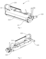
Fig. 1 is a schematic diagram of a three-dimensional structure of a cleaning device according to an embodiment of the present disclosure. -
Fig. 2 is a schematic diagram of a three-dimensional structure of the cleaning device according to the embodiment of the present disclosure from another perspective. -
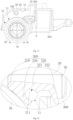
Fig. 3 is a cross-sectional view of the cleaning device according to an embodiment of the present disclosure. -
Fig. 4 is an enlarged view of portion I inFig. 3 . -
Fig. 5 is a schematic diagram of an assembly state of the cleaning device and a compression spring according to the embodiment of the present disclosure. -
Fig. 6 is a schematic diagram of the cleaning device in a disassembled state according to an embodiment of the present disclosure. -
Fig. 7 is an enlarged view of portion II inFig. 6 . -
Fig. 8 is a structural perspective view of a mopping-washing cleaning assembly according to an embodiment of the present disclosure. -
Fig. 9 is an exploded view of a structure of the mopping-washing cleaning assembly shown inFig. 8 . -
Fig. 10 is a top view of the mopping-washing cleaning assembly shown inFig. 8 . -
Fig. 11 is a cross-sectional view of the mopping-washing cleaning assembly shown inFig. 10 along the direction A-A. -
Fig. 12 is a partial enlarged view of portion B of the mopping-washing cleaning assembly shown inFig. 11 . -
Fig. 13 is a partial enlarged view of portion C of the mopping-washing cleaning assembly shown inFig. 9 . -
Fig. 14 is a perspective cross-sectional view of a bracket shown inFig. 11 . -
Fig. 15 is a perspective view of a structure of the water squeezing device and the sealing member shown inFig. 13 from another angle. -
Fig. 16 is a cross-sectional view of the mopping-washing cleaning assembly shown inFig. 10 along the direction E-E. -
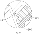
Fig. 17 is a cross-sectional view of a three-dimensional structure of the cleaning device according to an embodiment of the present disclosure from one perspective. -
Fig. 18 is an enlarged view of portion III inFig. 17 . - In the figure:
1, cleaning device; 10, cleaning drum; 11, fixing hole; 12, first positioning structure; 13, inner top wall; 15, sealing edge; 20, baffle; 21, abutting edge; 22, leading edge; 100, water injecting device; 110, weep hole; 200, water squeezing device; 210, squeezing part; 211, open slot; 212, third positioning structure; 220, diversion part; 221, first diversion section; 222, second diversion section; 230, fixing part; 300, water collecting tank; 310, notch; 320, first filtering device; 330, sewage pump; 340, second filtering device; 350, rubber plug; 400, dirt scraping comb; 50, mounting bracket; 510, cover plate; 520, swing arm; 530, drum driving motor; 610, clean water pipe; 620, sewage pipe; 630, compression spring; 641, circumferential limiter; 642, limiting buckle; 70, sealing member; 701, second positioning structure; 702, fourth positioning structure; 80, supporting plate. - In order to make the technical problem solved, the technical solution adopted, and the technical effect achieved by the present disclosure clearer, the technical solution of the embodiments of the present disclosure will be further described in detail with reference to the accompanying drawings. Obviously, the described embodiments are only a part of the embodiments of the present disclosure, not all of them. Based on the embodiments in the present disclosure, all other embodiments obtained by those skilled in the art without creative labor are within the scope of protection of the present disclosure.
- In the description of the present disclosure, unless otherwise specified and limited, the terms "connected" and "fixed" should be broadly understood, for example, it may be fixed connections, detachable connections, or integrated; or it may be a mechanical connection or an electrical connection; or it may be directly connected or indirectly connected through an intermediate medium; or it may be a connection within two components or an interaction relationship between two components. For those skilled in the art, the specific meanings of the above terms in the present disclosure may be understood in specific situations.
- In the present disclosure, unless otherwise specified and limited, a first feature "above" or "below" a second feature may include direct contact between the first and second features, or may include contact between the first and second features through another feature between them instead of direct contact. Moreover, the first feature being "above", "over", and "on" the second feature includes the first feature being directly above and diagonally above the second feature, or simply indicating that the first feature is horizontally higher than the second feature. The first feature being "below", "underneath", and "under" includes the first feature being directly below and diagonally below the second feature, or simply indicating that the first feature is horizontally lower than the second feature.
- An embodiment of the present disclosure provides a cleaning device, and the cleaning device is mainly used when a cleaning robot mops the floor, and is used to recover the sewage generated by mopping the floor while mopping the floor. The cleaning device may also be mounted on other devices and equipment, such as a handheld cleaning device. The embodiment of this description takes the example of the cleaning device being mounted on a cleaning robot for explanation.
- As shown in
Figs. 1-7 , thecleaning device 1 includes acleaning drum 10 and a water injectingdevice 100, awater squeezing device 200 and a sewage recovery device arranged on periphery of thecleaning drum 10. The water injecting device, the water squeezing device and the sewage recovery device are arranged in sequence in a rotation direction of thecleaning drum 10. - In this solution, the
cleaning drum 10 is provided as a mopping device. Thecleaning drum 10 cleans the ground during the rolling process. The water injectingdevice 100 is provided to provide clean water for thecleaning drum 10. On the one hand, thecleaning drum 10 is wetted, and the clean water is transferred to the ground through thecleaning drum 10 to facilitate wiping of the dirt on the ground. On the other hand, the dirt adsorbed by the cleaningdrum 10 is brought out of the cleaningdrum 10 under the action of the clean water of thewater injecting device 100 and thewater squeezing device 200, which can realize self-cleaning of the cleaningdrum 10, so that the cleaningdrum 10 can be kept in a clean state at all times, thereby improving the ground cleaning effect. - Moreover, the above device can reduce the manual cleaning of the cleaning
drum 10, reduce the human participation in the cleaning work of thecleaning device 1 itself, and improve practicality. - In this solution, after the
water injecting device 100 injects water on the cleaningdrum 10, the position of the cleaningdrum 10 with a large amount of water rotates to thewater squeezing device 200. Thewater squeezing device 200 and the cleaningdrum 10 are arranged to interfere with each other, and thewater squeezing device 200 is usually made of a material with strong rigidity, so that after the two are in contact, the cleaningdrum 10 is squeezed and deformed, and the water inside it carries the dirt therein to form sewage and flows out together. The outflowing sewage continues to flow along the rotation direction of the cleaningdrum 10 and flows to the sewage recovery device and is recovered by the sewage recovery device. On the one hand, it avoids the sewage dripping onto the ground, which causes secondary pollution of the ground. On the other hand, the sewage can be filtered and recycled. Under the condition of the same water tank volume, the cruising range of the water tank is extended. - In this solution, the
water injecting device 100, thewater squeezing device 200 and the sewage recovery device are arranged in sequence along the rotation direction of the cleaningdrum 10, so that when the cleaningdrum 10 rotates, water is first injected by thewater injecting device 100, then squeezed by thewater squeezing device 200, and finally flows into the sewage recovery device. In this way, the clean water will not be contaminated by the squeezed sewage, thereby ensuring the cleaning effect of the cleaningdrum 10 and improving the floor cleaning effect. - The sewage recovery device includes a
water collection groove 300. Thewater collection groove 300 has anotch 310 facing the cleaningdrum 10. Afirst filtering device 320 is disposed at thenotch 310. During use, the sewage is filtered by thefirst filtering device 320 and then enters thewater collecting tank 300 through thenotch 310. Thefirst filtering device 320 may filter out larger impurity particles in the sewage and only allow sewage containing smaller impurities to enter thewater collecting tank 300, so that the sewage is filtered and may be recycled. When the overall volume of the water tank is inconvenient, the cruising range of thecleaning device 1 can be extended. - The
water collecting tank 300 may be used as a temporary storage container for accumulated water. In this embodiment, asewage pump 330 is provided within thewater collecting tank 300. When the sewage in thewater collecting tank 300 accumulates to a certain extent, it may be pumped out by thesewage pump 330 and discharged into the sewage tank integrated in the cleaning robot or directly discharged into the sewer. Asecond filtering device 340 is disposed at the water inlet of thesewage pump 330, and thesecond filtering device 340 is used to filter the sewage again. In this solution, the second filtering device can filter impurities with a smaller volume than the first filtering device, further preventing the impurities from being sucked into thesewage pump 330 and causing damage to thesewage pump 330. Moreover, after the sewage is double filtered by thefirst filtering device 320 and thesecond filtering device 340, the impurity content therein will be greatly reduced, making it easier to recycle. - Alternatively, in this solution, the
first filtering device 320 and thesecond filtering device 340 are both filter screens, and the aperture of the second filter screen is smaller than that of the first filter screen, so that the second filter screen can filter smaller impurities. - It should be pointed out that, in order to further filter smaller impurities, the
second filtering device 340 may be filter cotton in addition to the filter mesh, or a combination of the filter mesh and the filter cotton. - Impurities filtered out by the
second filtering device 340 will accumulate near thesecond filtering device 340. When the impurities accumulate to a certain amount, the sewage will not be able to pass through thesecond filtering device 340 and be extracted by thesewage pump 330. Therefore, in this embodiment, a cleaning port is provided at thewater collecting tank 300 and located adjacent to thesecond filtering device 340. The accumulated impurities can be cleaned through the cleaning port to prevent thesecond filtering device 340 from being blocked. - Furthermore, in order to ensure that the cleaning port does not leak when cleaning is not required, a
rubber plug 350 is detachably provided at the cleaning port in this embodiment. When thecleaning device 1 is in normal working condition, therubber plug 350 is mounted in the cleaning port to seal the cleaning port. When it is necessary to clean the impurities in thewater collecting tank 300, therubber plug 350 may be removed from the cleaning port and therubber plug 350 may be mounted back after cleaning the impurities inside thewater collecting tank 300. - Alternatively, the
water injecting device 100 in this embodiment is a water supply pipe, an axial direction of the water supply pipe is parallel to an axial direction of the cleaningdrum 10, and a plurality of weepholes 110 are arranged on the water supply pipe in the axial direction. - The weep
hole 110 is arranged on the side of the water supply pipe facing the cleaningdrum 10. Preferably, the water supply pipe is arranged above the cleaningdrum 10, and the weephole 110 is arranged at the bottom of the water supply pipe. Each weephole 110 on the water supply pipe is connected to the inside of the water supply pipe. During use, water is supplied to the water supply pipe, and the water in the water supply pipe flows out through the weephole 110 and drips onto the cleaningdrum 10 to wet and clean the cleaningdrum 10. - The weep
holes 110 may be uniformly or non-uniformly arranged on the water supply pipe, and the number of the weepholes 110 may be reasonably designed based on the actual length and rotation speed of the cleaningdrum 10, which is not specifically limited in this solution. In the case where the weepholes 110 are arranged unevenly, the weepholes 110 in the middle of the water supply pipe may be arranged more densely, while the weepholes 110 near the end may be arranged more sparsely. In this way, more water in the middle will gradually diffuse to both ends. In this way, in addition to ensuring that the cleaningdrum 10 as a whole obtains enough water flow and is fully cleaned, it can also avoid excessive water flow at both ends of the cleaningdrum 10 causing overflow of cleaning water. - In particular, it can prevent the
cleaning drum 10 from being squeezed by the squeezing device when it contains a large amount of water, and the water suddenly overflows and untimely drainage will from if being untimely guided. - Moreover, the diffusion of more water in the middle to both ends also helps to discharge the dirt in the middle to both ends, thus preventing the dirt from accumulating in the middle and being difficult to clean.
- It should be pointed out that, in order to achieve the above-mentioned solution of large water volume in the middle and small water volume at both ends, it is not limited to the above-mentioned manner of arranging more densely the weep
holes 110 in the middle position of the water supply pipe and arranging relatively sparsely the weepholes 110 near the end positions. In other embodiments, the weepholes 110 may be evenly arranged in number along the length direction of the water supply pipe, and in terms of the size of the weepholes 110, the weepholes 110 near the middle position of the water supply pipe are larger in size, and a larger amount of water may flow out through them, while the weepholes 110 near the end positions of the water supply pipe are smaller in size, and a smaller amount of water may flow out through them. - The water squeezing device in this solution may be in various forms. Alternatively, in this embodiment, the
water squeezing device 200 is a water pressing rod arranged against the cleaningdrum 10 along the axial direction of the cleaningdrum 10, and the length of the water pressing rod in the axial direction of the cleaningdrum 10 is greater than or equal to the length of the cleaningdrum 10. That is, the water pressing rod may cover the entire length direction of the cleaningdrum 10, so that during the rotation of the cleaningdrum 10, the water absorbed at various positions along the length direction can be squeezed out. - In this embodiment, the water pressing rod is one, and its length is the same as that of the cleaning
drum 10. When it is arranged, the axial direction of the water pressing rod is parallel to the axial direction of the cleaningdrum 10, and the two ends of the water pressing rod are respectively aligned with the two ends of the cleaningdrum 10. In other embodiments, the water pressing rod may also have other shapes or arrangements. - For example, in other embodiments, the water pressing rod may be arranged in a V-shaped structure or an arc-shaped structure, and the water pressing rod gradually inclines toward a side away from the water injecting device from the middle to both ends. When the water pressing rod is in the above-mentioned shape, the middle position of the water pressing rod first contacts the cleaning
drum 10, and the sewage squeezed out by the cleaningdrum 10 flows to both sides along the body of the water pressing rod, and mixes with the sewage squeezed out by the bodies of the water pressing rods on both sides to form a larger water flow, which can flush away the dirt that is larger in volume or more tightly adhered to the cleaningdrum 10. - The water pressing rod described in this solution is not limited to the above-mentioned structure of arranging only one water pressing rod. In other embodiments, the water pressing rod may be multiple water pressing rods, and the multiple water pressing rods are sequentially arranged along the axial direction of the cleaning
drum 10. - In the case where there are multiple water pressing rods, the sum of the lengths of all the water pressing rods may be the same as the total length of the cleaning
drum 10, that is, each water pressing rod may squeeze water from a section of the cleaningdrum 10, or the sum of the lengths of all the water pressing rods is greater than the total length of the cleaningdrum 10, and adjacent water pressing rods are parallel and staggered, and two adjacent water pressing rods partially overlap in the length direction of the cleaningdrum 10. - By providing multiple water pressing rods and each water pressing rod is not located in the same straight line, the extrusion force exerted by the water pressing rod on the cleaning
drum 10 is directed to the axis of the cleaningdrum 10 from different directions. Compared with only providing one columnar water pressing rod, this solution can disperse the force on the cleaningdrum 10 and avoid applying excessive extrusion force on the cleaningdrum 10 in one direction, which may affect the rotation of the cleaningdrum 10. - As a preferred technical solution of the present disclosure, the water pressing rod in this embodiment is a columnar aluminum rod.
- It should be pointed out that the shape of the water pressing rod includes but is not limited to a circular, elliptical, hexagonal, pentagonal, rectangular, square, triangular and other shapes in cross section. It may also be of a special shape, as long as it has an action line or action surface that can exert a squeezing force on the cleaning
drum 10. - Moreover, the material of the water pressing rod is not limited to aluminum. In other solutions of the present disclosure, a plastic rod or a nylon rod may also be used as the water pressing rod.
- As a preferred technical solution of the cleaning device, the water pressing rod may be fixed, or the water pressing rod may be rotatable relative to the cleaning
drum 10. - In this solution, the relative rotation of the water pressing rod and the cleaning
drum 10 is preferably synchronous relative rotation. Under this structure, the water pressing rod only squeezes the cleaningdrum 10 to squeeze out the water inside it. This solution preferably adopts that the rotation of the water pressing rod is in contact with the cleaning rolling surface, and the rolling friction force of the cleaningdrum 10 drives the water pressing rod to rotate. - The rotation of the water pressing rod is not limited to being driven only by the friction force of the cleaning
drum 10. In other embodiments, a rotational driving force may be provided separately for the cleaningdrum 10, and the rotation of the cleaningdrum 10 and the rotation of the water pressing rod may be arranged to be synchronized, so that the surfaces of the cleaningdrum 10 in contact with the water pressing rod do not slide relative to each other. - In other embodiments, the water pressing rod and the cleaning
drum 10 may rotate relative to each other asynchronously, that is, a rotational driving force is provided to the water pressing rod alone so that the rotation between the two is asynchronous. Under this structure, in addition to squeezing and draining the cleaningdrum 10, the surface of the water pressing rod may also slide relative to the surface of the cleaningdrum 10, thereby further scraping off dirt on the surface of the cleaningdrum 10. - It should be pointed out that the
water squeezing device 200 in the present disclosure is not limited to a rod-shaped structure. In other embodiments, a water-pressing scraper may also be used as thewater squeezing device 200. The water-pressing scraper has a squeezing surface facing the cleaningdrum 10, and the squeezing surface is parallel to the axis of the cleaningdrum 10. - The sewage recovery device in this embodiment is used to collect sewage containing dirt squeezed out from the cleaning
drum 10 by the squeezingdevice 200. The sewage recovery device includes awater collecting tank 300. Thewater collecting tank 300 has anotch 310 facing the cleaningdrum 10. Thenotch 310 is provided with afirst filtering device 320. During use, the sewage is filtered by thefirst filtering device 320 and then enters thewater collecting tank 300 through thenotch 310. The filtering device can filter larger impurity particles in the sewage and only allows sewage containing smaller impurities to enter thewater collecting tank 300. - The
cleaning device 1 according to this embodiment further includes a mountingbracket 50, and thewater injecting device 100, thewater squeezing device 200 and the sewage recovery device are all mounted on the mountingbracket 50. Thecleaning device 1 is mounted on the cleaning robot through the mountingbracket 50. That is, in this solution, the cleaningdrum 10 may be rotationally arranged relative to the mountingbracket 50, and the side of the cleaningdrum 10 facing the ground protrudes from the mountingbracket 50, so that it can fully contact the ground during operation. - Alternatively, as shown in
Figs. 1, 2 ,5 and6 , the mountingbracket 50 in this embodiment includes acover plate 510 and swingarms 520 extending from both ends of thecover plate 510 to the same side, and thecleaning device 1 is movably mounted on the cleaning robot through theswing arms 520. - In this embodiment, the
swing arm 520 is hinged to the cleaning robot, and the axis of the cleaningdrum 10 and the axis of the hinge axis of theswing arm 520 and the cleaning robot are arranged parallel to each other, so that the cleaningdrum 10 may swing around the hinge axis so that the interference amount between the cleaningdrum 10 and the ground and whether it is in contact with the ground may be adjusted. Moreover, when the cleaning robot passes over an obstacle, the roller may pass over the obstacle by swinging. - In order to further clean the cleaning
drum 10, as shown inFig. 4 , in this embodiment, adirt scraping comb 400 is further provided at upstream of thewater injecting device 100 in the rotation direction of the cleaningdrum 10. Thedirt scraping comb 400 is used to clean larger dirt adhered to the surface of the cleaningdrum 10, for example, it can remove hair adhered to the cleaningdrum 10. - As shown in
Figs. 1 and 2 , in order to realize the rotation of the cleaningdrum 10, thecleaning device 1 according to this embodiment further includes adrum driving motor 530 and a transmission device. The cleaningdrum 10 is rotated by thedrum driving motor 530. The transmission device is disposed between the cleaningdrum 10 and thedrum driving motor 530, and is used to transmit the rotation of the power output shaft of thedrum driving motor 530 to the cleaningdrum 10 and adjust the rotation speed. - Optionally, in an embodiment of the present disclosure, as shown in
Figs. 8 to 11 ,Fig. 8 is a structural perspective view of the cleaning device according to this embodiment,Fig. 9 is a exploded view of a structure of the cleaning device shown inFig. 8 ,Fig. 10 is a top view of the cleaning device shown inFig. 8 , andFig. 11 is a cross-sectional view of the cleaning device shown inFig. 10 along the A-A direction. The cleaning device includes a mountingbracket 50, a cleaningdrum 10, abaffle 20, a sewage recovery device including awater collecting tank 300, awater squeezing device 200 and awater injecting device 100. Thewater injecting device 100, thewater squeezing device 200 and the sewage recovery device are arranged in sequence, and thewater collecting tank 300 has anotch 310 facing the cleaningdrum 10, and the sewage enters thewater collecting tank 300 through thenotch 310. - The cleaning
drum 10 is rotationally connected to the mountingbracket 50, and thebaffle 20 is arranged at both ends of the cleaningdrum 10. Thebaffle 20 is provided with an abuttingedge 21. An abuttingedge 21 of thebaffle 20 squeezes the cleaningdrum 10 to prevent the sewage on the cleaningdrum 10 from passing through thebaffle 20 along the axial direction of the cleaningdrum 10. Thewater collecting tank 300 is disposed at a side of the cleaningdrum 10, and thewater squeezing device 200 is disposed between thebaffles 20 on both ends of the cleaningdrum 10. Thewater squeezing device 200 squeezes the cleaningdrum 10 and extends toward thewater collecting tank 300. Thewater injecting device 100 is opposite to the cleaningdrum 10, and thewater injecting device 100 may inject the cleaning liquid toward the cleaningdrum 10. - Alternatively, as shown in
Fig. 11 , the orientation or position relationship shown inFig. 11 is used for exemplary description. Thewater squeezing device 200 is located at the upper right of the cleaningdrum 10. When the cleaningdrum 10 rolls along a first direction D1 around its own axis, the cleaningdrum 10 drives thecleaning device 1 forward. The circumferential outer side of the cleaningdrum 10 continuously rolls in contact with the ground and wipes the ground. The circumferential outer side of the cleaningdrum 10 also continuously rolls in contact with thewater squeezing device 200. The part of the cleaningdrum 10 that contacts thewater squeezing device 200 leaks sewage under the squeezing action of thewater squeezing device 200, and flows to thewater squeezing device 200, and is guided to thewater collecting tank 300 through thewater squeezing device 200. Thewater collecting tank 300 temporarily stores the sewage introduced by thewater squeezing device 200, so that thecleaning device 1 can recover the sewage generated on the cleaningdrum 10 while mopping the ground. InFig. 11 , the first direction is the clockwise direction. - When the cleaning
drum 10 rolls, thewater injecting device 100 may inject cleaning liquid toward the cleaningdrum 10. After the cleaning liquid falls into the cleaningdrum 10, it mixes with the dirt on the cleaningdrum 10 and becomes sewage. - It should be noted that the cleaning
drum 10 shown inFig. 11 is for illustration only. In a specific implementation, the circumferential outer side of the cleaningdrum 10 has a fluffy structure, and the circumferential outer side of the cleaningdrum 10 abuts against the abuttingedge 21. When the cleaningdrum 10 is squeezed by the abuttingedge 21, the squeezed portion of the cleaningdrum 10 may be compressed and the outer diameter becomes smaller accordingly. - In the
cleaning device 1 according to the present embodiment, thebaffle 20 is arranged at the two ends of the cleaningdrum 10, and the abuttingedge 21 of thebaffle 20 squeezes the cleaningdrum 10 and blocks the sewage on the cleaningdrum 10 from passing through thebaffle 20 along the axial direction of the cleaningdrum 10, thereby limiting the sewage adsorbed on the cleaningdrum 10 between thebaffles 20 at the two ends of the cleaningdrum 10, preventing the sewage on the cleaningdrum 10 from flowing to the ground from the two ends of the cleaningdrum 10, and thewater squeezing device 200 is arranged between thebaffles 20 on the two ends of the cleaningdrum 10. When the part of the cleaningdrum 10 adsorbing the sewage turns to contact thewater squeezing device 200, the sewage seeps out under the squeezing of thewater squeezing device 200 and flows downstream to thewater squeezing device 200, and is then guided to thewater collecting tank 300 by thewater squeezing device 200. In this way, the loss rate of sewage on the cleaningdrum 10 is reduced, and thecleaning device 1 effectively collects the sewage on the cleaningdrum 10. - Since the circumferential outer side of the cleaning
drum 10 has a fluffy structure, the circumferential outer side of the cleaningdrum 10 can be compressed by making the abuttingedge 21 of thebaffle 20 squeeze the cleaningdrum 10. The part of the cleaningdrum 10 squeezed by the abuttingedge 21 presses against the abuttingedge 21 under the action of its own elastic force, thereby eliminating the gap between the two parts of the abuttingedge 21 and the cleaningdrum 10 that contact each other, so that the two parts of the abuttingedge 21 and the cleaningdrum 10 that contact each other are relatively close, effectively blocking the sewage from passing through the two parts of the abuttingedge 21 and the cleaningdrum 10 that contact each other. Moreover, the part of the cleaningdrum 10 squeezed by the abuttingedge 21 may also be compacted, so that the part of the cleaningdrum 10 squeezed by the abuttingedge 21 is relatively dense, effectively blocking the sewage from passing through the part of the cleaningdrum 10 squeezed by the abuttingedge 21. In this way, the blocking effect of thebaffle 20 on the sewage on the cleaningdrum 10 is guaranteed. - Sequentially referring to the figures, in some embodiments, the
baffle 20 is perpendicular to the cleaningdrum 10, and the abuttingedge 21 is an arc, and the arc is matched with the circumferential outer side of the cleaningdrum 10. Through the above arrangement, the abuttingedge 21 and the cleaningdrum 10 are more closely matched when they contact each other. When the abuttingedge 21 squeezes the cleaningdrum 10, the abuttingedge 21 as a whole may be firmly attached to the cleaningdrum 10 along the outer circumference of the cleaningdrum 10, and the center of the abuttingedge 21 coincides with the axis of the cleaningdrum 10, that is, the abuttingedge 21 is always firmly attached to the cleaningdrum 10 from one end to the other end, avoiding water leakage due to a gap between the abuttingedge 21 and the cleaningdrum 10. The sewage between the two ends of the cleaningdrum 10 can basically only be transferred to thewater squeezing device 200 with the cleaningdrum 10, and seep out and flow to thewater collecting tank 300 under the squeezing of thewater squeezing device 200. - The arc shape being adapted to the circumferential outer side of the cleaning
drum 10 means that when the abuttingedge 21 of thebaffle 20 squeezes the cleaningdrum 10, the portion of the cleaningdrum 10 squeezed by the abuttingedge 21 is compressed and the corresponding outer diameter becomes smaller. At this time, the outer diameter of the portion of the cleaningdrum 10 squeezed by the abuttingedge 21 is equal to the diameter of the abuttingedge 21. - It can be understood that since the circumferential outer side of the cleaning
drum 10 has a fluffy structure, when the cleaningdrum 10 rolls, the portion of the cleaningdrum 10 to be squeezed by the abuttingedge 21 is in a fluffy state, gradually enters a squeezing region from one end of the abuttingedge 21, and enters a compressed state; as the cleaningdrum 10 continues to roll, the portion squeezed by the abuttingedge 21 is in a compressed state, gradually withdraws from the squeezing region corresponding to the abuttingedge 21 from the other end of the abuttingedge 21, and returns to the fluffy state. Since one end of the abuttingedge 21 is firmly attached to the cleaningdrum 10, the portion of the cleaningdrum 10 to be squeezed by the abuttingedge 21 is in a fluffy state and is difficult to directly enter the squeezing region from one end of the abuttingedge 21, and may even get stuck. Therefore, in some embodiments, thebaffle 20 is further provided with aleading edge 22, one end of the leadingedge 22 is tangent to one end of the abuttingedge 21, and the other end of the leadingedge 22 extends in a direction away from the axis of the cleaningdrum 10 and toward the downward direction, the distances between each point on the abuttingedge 21 and the axis of the cleaningdrum 10 are equal everywhere, and the distances between each point on the leadingedge 22 and the axis of the cleaningdrum 10 increase with the increase of the extension length of the leadingedge 22 at the point. In this way, before the part of the cleaningdrum 10 to be squeezed by the abuttingedge 21 enters the squeezing region corresponding to the abuttingedge 21, the leadingedge 22 can pre-extrude the part of the cleaningdrum 10 to be squeezed by the abuttingedge 21, and smoothly introduce the part of the cleaningdrum 10 to be squeezed by the abuttingedge 21 into the squeezing region corresponding to the abuttingedge 21, so that the cleaningdrum 10 can still maintain smooth rolling under the squeezing action of thebaffle 20, thereby avoiding the part of the cleaningdrum 10 to be squeezed by the abuttingedge 21 from being stuck at one end of the abuttingedge 21. - In some embodiments, the leading
edge 22 is arc-shaped. - In other embodiments, the leading
edge 22 has a straight line shape. - Referring to
Fig. 12, Fig. 12 is a partial enlarged view of portion B of thecleaning device 1 shown inFig. 11 . In some embodiments, thewater squeezing device 200 includes a squeezingpart 210 and adiversion part 220. The squeezingpart 210 presses the cleaningdrum 10. Thediversion part 220 includes afirst diversion section 221 and asecond diversion section 222. Thefirst diversion section 221 extends from the squeezingpart 210 to above thewater collecting tank 300. Thesecond diversion section 222 extends downwardly and obliquely from one end of thefirst diversion section 221 away from the squeezingpart 210 into thewater collecting tank 300. The part of the cleaningdrum 10 that contacts the squeezingpart 210 leaks sewage under the squeezing action of the squeezingpart 210. The sewage flows over the squeezingpart 210 and is introduced into thewater collecting tank 300 through thefirst diversion section 221 and thesecond diversion section 222 in sequence. Through the above arrangement, when the sewage flows along thefirst diversion section 221 to the end of thefirst diversion section 221 away from the squeezingpart 210, it may follow thesecond diversion section 222 to fall into thewater collecting tank 300 in a downward tilt. The sewage that has separated from thesecond diversion section 222 falls into thewater collecting tank 300 roughly along a direction parallel to thesecond diversion section 222. In this way, it can be avoided that the sewage flies horizontally into thewater collecting tank 300 after separating from thewater squeezing device 200, thereby reducing the noise of sewage falling. Moreover, the guiding effect of thesecond diversion section 222 can make the sewage fall into a preset position in thewater collecting tank 300, and the preset position may be an outer region of the filter structure in thewater collecting tank 300. That is, after the sewage falls into the preset position, the sewage may pass through the filter structure and enter the inner region of the filter structure, thereby realizing the filtration of the sewage and avoiding the sewage from falling directly from thewater squeezing device 200 into an inner region of the filter structure. - The squeezing
device 200 is disposed at the outer side of the cleaningdrum 10 in the circumferential direction and parallel to the axial direction of the cleaningdrum 10. - The
first diversion section 221 extends along the forward direction of the cleaningdrum 10 and extends downwardly to the top of thewater collecting tank 300, and thesecond diversion section 222 extends along the forward direction of the cleaningdrum 10 and extends downwardly to thewater collecting tank 300, and the inclination angle of thesecond diversion section 222 is greater than the inclination angle of thefirst diversion section 221. It should be further explained that there may be an angle between thefirst diversion section 221 and thesecond diversion section 222, and the angle may be set according to actual needs/situations. - In some embodiments, the
water squeezing device 200 further includes a fixingpart 230, and the fixingpart 230 is fixedly connected to the squeezingpart 210 and/or thediversion part 220, and the fixingpart 230 is provided with anopen slot 211. The mountingbracket 50 is provided with a fixinghole 11, and the fixinghole 11 is opposite to and communicates with theopen slot 211. Theopen slot 211 and the fixinghole 11 are used to cooperate with each other to allow an external fixing member to penetrate, so that thewater squeezing device 200 is fixed on the mountingbracket 50. - In a specific implementation process, screws may be screwed into the fixing holes 11 and the
open slots 211 in sequence, thereby fixing thewater squeezing device 200 on the mountingbracket 50. It is understandable that providing an annular closed hole on thewater squeezing device 200 to cooperate with the screw is relatively difficult in terms of manufacturing process. However, adopting anopen slot 211 structure to cooperate with the fixinghole 11 may reduce the difficulty of the manufacturing process of thewater squeezing device 200. In addition, theopen slot 211 structure can not only radially limit the screw, but also radially expand and deform to adapt to screws with larger outer diameters. - The
open slot 211 may be a U-shaped groove. - As shown in
Fig. 12 , in some embodiments, the fixingpart 230 is disposed below the squeezingpart 210 and thefirst diversion section 221, and is fixedly connected to the squeezingpart 210 and thefirst diversion section 221. Therefore, after the fixingpart 230 is fixed to the mountingbracket 50 by screws or the like, it can provide better support for thewater squeezing device 200 as a whole, optimize the force structure of thewater squeezing device 200, and resist the force from the cleaningdrum 10. - In some embodiments, the
water injecting device 100 is arranged along the axis parallel to the cleaningdrum 10, and thewater injecting device 100 is provided with a plurality of water inject holes spaced along its own axis. The plurality of water inject holes are located between thebaffles 20 on both ends of the cleaningdrum 10, and the orifices of the water inject holes face the cleaningdrum 10. - The cleaning liquid may be clean water, detergent or a mixture of clean water and detergent.
- Referring to
Figs. 12 and13, Fig. 13 is a partial enlarged view of portion C of thecleaning device 1 shown inFig. 9 . In some embodiments, thecleaning device 1 further includes sealingmembers 70, and the sealingmembers 70 are respectively arranged at both ends of thewater squeezing device 200. The sealingmember 70 seals the gap between thebaffle 20 and thewater squeezing device 200. The sealingmember 70 can block the sewage on thewater squeezing device 200 from passing through the sealingmember 70 along the length direction of thewater squeezing device 200. In this way, the sewage on the cleaningdrum 10 can flow only to thewater squeezing device 200 as much as possible, and is limited between the sealingmembers 70 on both ends of thewater squeezing device 200, preventing the sewage on the cleaningdrum 10 from losing from the gap between thebaffle 20 and thewater squeezing device 200, so that the sewage flowing through thewater squeezing device 200 flows only to thewater collecting tank 300 as much as possible, thereby reducing the sewage loss rate and ensuring the effective collection of sewage by thecleaning device 1. - Referring to
Fig. 14, Fig. 14 is a perspective cross-sectional view of the mountingbracket 50 shown inFig. 11 . In some embodiments, the mountingbracket 50 is provided with afirst positioning structure 12, and the sealingmember 70 is provided with asecond positioning structure 701. Thefirst positioning structure 12 and thesecond positioning structure 701 are matched with each other to achieve rapid positioning and assembly between the sealingmember 70 and the mountingbracket 50, so that the installation angle of the sealingmember 70 relative to the mountingbracket 50 is fixed. Moreover, thefirst positioning structure 12 and thesecond positioning structure 701 that are positioned with each other can play a certain limiting role on the sealingmember 70, so that the sealingmember 70 is firmly assembled between the mountingbracket 50 and thewater squeezing device 200. - In some embodiments, referring to
Figs. 17 and18 , thefirst positioning structure 12 is a positioning groove, and thesecond positioning structure 701 is a positioning protrusion, and the positioning protrusion is inserted into the positioning groove. - In other embodiments, the
first positioning structure 12 is a positioning protrusion, and thesecond positioning structure 701 is a positioning groove, and the positioning protrusion is inserted into the positioning groove. - In some embodiments, the sealing
member 70 may be made of a soft rubber material, and the soft rubber may allow the sealingmember 70 to be in an interference fit state when sealing thebaffle plate 20 and thewater squeezing device 200, thereby providing better sealing and waterproofing effects. - During the specific implementation process, the
baffle 20 extends from the innertop wall 13 of the mountingbracket 50 toward the cleaningdrum 10 and the sealingmember 70, and forms an abuttingedge 21 above the cleaningdrum 10, and forms a sealing edge 104 above the sealingmember 70. The sealing edge 104 is sealed with the sealingmember 70. In this way, thebaffle 20 can play a better role in isolating the sewage on the cleaningdrum 10 and thewater squeezing device 200, preventing the sewage on the cleaningdrum 10 and thewater squeezing device 200 from splashing out from the two ends of the cleaningdrum 10 and the two ends of thewater squeezing device 200 respectively. - Referring to
Figs. 13 and15, Fig. 15 is a perspective view of a structure of thewater squeezing device 200 and the sealingmember 70 shown inFig. 13 from another angle. In some embodiments, thewater squeezing device 200 is provided with athird positioning structure 212, and the sealingmember 70 is provided with afourth positioning structure 702. Thethird positioning structure 212 and thefourth positioning structure 702 are matched with each other to achieve rapid positioning and assembly between thewater squeezing device 200 and the sealingmember 70, so that the installation angle of thewater squeezing device 200 relative to the sealingmember 70 is fixed. Moreover, thethird positioning structure 212 and thefourth positioning structure 702 that are positioned with each other can play a certain limiting role on thewater squeezing device 200, so that thewater squeezing device 200 is firmly assembled on the mountingbracket 50. - In some embodiments, the
third positioning structure 212 is a first step surface, and the first step surface is arranged at the end position of thewater squeezing device 200, thefourth positioning structure 702 is a second step surface, and the second step surface is arranged at the end position of the sealingmember 70. The first step surface and the second step surface fit together so that after thewater squeezing device 200 is assembled with the sealingmember 70, the part of thewater squeezing device 200 used to squeeze the cleaningdrum 10 is facing the cleaningdrum 10, that is, the squeezingpart 210 of thewater squeezing device 200 is facing the cleaningdrum 10, thereby realizing rapid positioning and assembly of thewater squeezing device 200, and moreover, playing an fool-proofing effect to prevent thewater squeezing device 200 from being mounted upside down, causing the squeezingpart 210 to face away from the cleaningdrum 10. - Alternatively, the first step surface is arranged at the end surface position of the squeezing
part 210, and the second step surface is arranged on the side of the sealingmember 70 close to the cleaningdrum 10. When thewater squeezing device 200 and the sealingmember 70 are assembled, the first step surface and the second step surface need to correspond to and cooperate with each other so that thewater squeezing device 200 and the sealingmember 70 can be mounted and matched, so that the squeezingpart 210 of thewater squeezing device 200 is facing the cleaningdrum 10 during installation. At this time, the distance between the second step surfaces of the sealingmember 70 corresponding to the two ends of thewater squeezing device 200 is equal to the longitudinal length of the squeezingpart 210. In this way, thewater squeezing device 200 may be prevented from being accidentally mounted upside down during the installation process. It should be noted that when thewater squeezing device 200 and the sealingmember 70 are assembled, if the first step surface and the second step surface do not correspond to each other, when thewater squeezing device 200 cooperates with the sealingmember 70 at an angle with its squeezingpart 210 facing away from the cleaningdrum 10, since the distance between the end surfaces of the sealingmember 70 corresponding to the two ends of thewater squeezing device 200 is smaller than the longitudinal length of the squeezingpart 210, thewater squeezing device 200 and the sealingmember 70 cannot be cooperated and mounted. The longitudinal length of the squeezingpart 210 is parallel to the axial length of the cleaningdrum 10. - During assembly, the sealing
member 70 may be first mounted on the two ends of the mountingbracket 50 through the mutual cooperation of the positioning groove and the positioning protrusion, and then, through the mutual cooperation of the first step surface and the second step surface, the two ends of thewater squeezing device 200 are respectively equipped with the sealingmember 70 on the two ends of the mountingbracket 50. Moreover, thewater squeezing device 200 is pressed against thebaffle 20, so that the sealingmember 70 is pressed between thebaffle 20 and thewater squeezing device 200, thereby forming an interference fit. - Referring to
Fig. 16, Fig. 16 is a cross-sectional view of thecleaning device 1 shown inFig. 10 along the E-E direction. In some embodiments, thecleaning device 1 further includes a supportingplate 80, and the supportingplate 80 is supported on the top of thewater squeezing device 200, so that thewater squeezing device 200 as a whole may be pressed against the cleaningdrum 10 to resist deformation of thewater squeezing device 200 caused by the force of the cleaningdrum 10. The first direction D1 is opposite to the second direction D2. InFig. 15 , the second direction D2 is the counterclockwise direction. - Alternatively, the
abutment plate 80 extends from the innertop wall 13 of the mountingbracket 50 toward thefirst diversion part 220 and thesecond diversion part 220, and theabutment plate 80 abuts against thefirst diversion part 220 and thesecond diversion part 220, so that thewater squeezing device 200 as a whole is always pressed against the cleaningdrum 10 in the vertical and horizontal directions, preventing the cleaningdrum 10 from rolling around its own axis and the force generated by the cleaningdrum 10 on thewater squeezing device 200 forcing thewater squeezing device 200 to warp up or bend horizontally. - In some embodiments, the abutting
plate 80 abuts against a middle position of thewater squeezing device 200. - Moreover, according to this embodiment, a cleaning robot is further provided, the cleaning robot includes a robot body and the
cleaning device 1 as described above. The cleaning robot according to the embodiment of the present disclosure also has the advantages of thecleaning device 1 described above, which will not be described in detail here. Thecleaning device 1 is arranged on the side of the robot body facing the ground, and acompression spring 630 is arranged between the robot body and thecleaning device 1. Thecompression spring 630 is configured to always apply a force to thecleaning device 1 toward the ground. Aclean water pipe 610 and asewage pipe 620 are provided at the robot body. Theclean water pipe 610 is connected to the water injecting device, and thesewage pipe 620 is connected to the sewage recovery device. - Referring to
Figs. 6 and 7 , in this embodiment, thecompression spring 630 is disposed at thecover plate 510, and a spring fixing member is disposed at thecover plate 510. Thecompression spring 630 is detachably mounted on thecover plate 510 through the spring fixing member. - The spring fixing member includes a plurality of circumferential limiting
members 641, the plurality of circumferential limitingmembers 641 enclose a spring installation groove at the bottom of thecover plate 510 , and a limitingbuckle 642 is arranged between adjacent twocircumferential limiting members 641, so that thecompression spring 630 may be clamped in the spring installation groove. - During the operation of the cleaning robot according to the present solution, the
cleaning device 1 is hinged to the bottom of the cleaning robot body through theswing arm 520, and the pressure applied by thecompression spring 630 enables it to fully contact the ground. After starting to work, clean water flows into the water supply pipe from theclean water pipe 610, and drips onto the surface of the cleaningdrum 10 through the weephole 110 on the water supply pipe. The cleaning robot starts to move and the cleaningdrum 10 rotates under the drive of thedrum driving motor 530. The cleaningdrum 10 adsorbed with clean water passes through the water pressing rod in turn as it rotates to discharge excess water. The discharged water enters thewater collecting tank 300 through thefirst filtering device 320, and the cleaningdrum 10 continues to rotate to squeeze out excess water. When the cleaningdrum 10, which is still moist, is in contact with the ground, it cleans the ground and continues to rotate after being adhered to dirt. When it reaches thedirt scraping comb 400, larger dirt is blocked by thedirt scraping comb 400 and falls off, while smaller dirt continues to rotate along with the cleaningdrum 10 through thedirt scraping comb 400 to the water supply pipe. The water injected from the water supply pipe can moisten the cleaningdrum 10. After that, when the cleaningdrum 10 passes through the water pressing rod again, the water pressing rod squeezes out the sewage to clean the cleaningdrum 10. The cleaned sewage enters thewater collecting tank 300 after being filtered by thefirst filtering device 320, and is pumped into the sewage tank through thesewage pump 330 in thewater collecting tank 300 for recycling. - In the description, it should be understood that the terms "up", "down", "left", "right" and other directional or positional relationships are based on the directional or positional relationships shown in the accompanying drawings, only for the convenience of description and simplification of operation, and do not indicate or imply that the device or component referred to must have a specific orientation, be constructed and operated in a specific orientation, and therefore cannot be understood as a limitation of the present disclosure. In addition, the terms "first" and "second" are only used to distinguish in description and do not have any special meaning.
- In the description, the reference to the terms "one embodiment", "example", etc. means that the specific features, structures, materials, or characteristics described in conjunction with the embodiment or example are included in at least one embodiment or example of the present disclosure. In this description, the illustrative expressions of the above terms may not necessarily refer to the same embodiments or examples.
- In addition, it should be understood that although this description is described according to the embodiments, not each embodiment only contains an independent technical solution. This description in the description is only for clarity, and those skilled in the art should consider the description as a whole. The technical solutions in each embodiment may also be appropriately combined to form other embodiments that those skilled in the art can understand.
- The technical principle of the present disclosure is described above in conjunction with specific embodiments. These descriptions are only intended to explain the principles of the present disclosure and cannot be interpreted in any way as limiting the scope of protection of the present disclosure. Based on the explanation here, those skilled in the art do not need to exert creative labor to associate with other specific embodiments of the present disclosure, which will fall within the scope of protection of the present disclosure.
Claims (31)
- A cleaning device, characterized by comprising a cleaning drum, a water injecting device, a water squeezing device and a sewage recovery device, wherein the water injecting device, the water squeezing device and the sewage recovery device are arranged on periphery of the cleaning drum,
the water injecting device, the water squeezing device and the sewage recovery device are arranged in sequence in a rotation direction of the cleaning drum, and the sewage recovery device includes a water collecting tank, and the water collecting tank has a notch facing the cleaning drum. - The cleaning device of claim 1, wherein a first filtering device is disposed at the notch.
- The cleaning device of claim 1 or 2, wherein a sewage pump is provided within the water collecting tank, and a second filtering device is disposed at the water inlet of the sewage pump.
- The cleaning device of claim 3, wherein a cleaning port is provided at the water collecting tank and located adjacent to the second filtering device, and a rubber plug is detachably provided at the cleaning port.
- The cleaning device of any one of claims 1-4, wherein the water injecting device is a water supply pipe, an axial direction of the water supply pipe is parallel to an axial direction of the cleaning drum, and a plurality of weep holes are arranged on the water supply pipe in the axial direction.
- The cleaning device of claim 5, wherein the water supply pipe is arranged above the cleaning drum, and the weep holes are arranged on a side of the water supply pipe facing the cleaning drum.
- The cleaning device of claim 5 or 6, wherein the weep holes are uniformly arranged on the water supply pipe.
- The cleaning device of claim 5 or 6, wherein the weep holes are non-uniformly arranged on the water supply pipe, and the density of the weep holes arranged in the middle of the water supply pipe is greater than that of the weep holes arranged near the ends of the water supply pipe.
- The cleaning device of any one of claims 1-8, wherein the water squeezing device is a water pressing rod arranged against the cleaning drum along the axial direction of the cleaning drum.
- The cleaning device of claim 9, wherein the length of the water pressing rod in the axial direction of the cleaning drum is greater than or equal to that of the cleaning drum.
- The cleaning device of claim 9, wherein the water pressing rod is arranged in a V-shaped structure or an arc-shaped structure, and the water pressing rod gradually inclines toward a side away from the water injecting device from the middle to both ends.
- The cleaning device of claim 9, wherein the number of the water pressing rods are multiple, and the multiple water pressing rods are sequentially arranged along the axial direction of the cleaning drum.
- The cleaning device of claim 9, wherein the water pressing rod is an aluminum rod, a plastic rod or a nylon rod.
- The cleaning device of claim 9, wherein the water pressing rod is fixed, or the water pressing rod is rotatable relative to the cleaning drum.
- The cleaning device of any one of claims 1-4, wherein the water squeezing device is a water-pressing scraper, the water-pressing scraper has a squeezing surface facing the cleaning drum, and the squeezing surface is parallel to the axis of the cleaning drum.
- The cleaning device of any one of claims 1-4, wherein the cleaning device further includes a mounting bracket, the water injecting device, the water squeezing device and the sewage recovery device are all mounted on the mounting bracket, and the cleaning device is mounted on the cleaning robot through the mounting bracket.
- The cleaning device of claim 16, wherein the mounting bracket includes a cover plate and swing arms extending from both ends of the cover plate to the same side, and the cleaning device is movably mounted on the cleaning robot through the swing arms.
- The cleaning device of any one of claims 1-4, wherein a dirt scraping comb is further provided at upstream of the water injecting device in the rotation direction of the cleaning drum.
- The cleaning device of any one of claims 1-4, wherein the cleaning device further includes a drum driving motor and a transmission device, and the cleaning drum is rotated by the drum driving motor.
- The cleaning device of any one of claims 1-19, wherein the cleaning device further comprises a mounting bracket and baffles,the mounting bracket is rotationally connected to the cleaning drum;the baffles are arranged at both ends of the cleaning drum, the baffle is provided with an abutting edge, the abutting edge of the baffle squeezes the cleaning drum to prevent the sewage on the cleaning drum from passing through the baffle along the axial direction of the cleaning drum;the water collecting tank is disposed at a side of the cleaning drum;the water squeezing device is disposed between the baffles arranged on both ends of the cleaning drum, the water squeezing device squeezes the cleaning drum and extends toward the water collecting tank;the water injecting device is opposite to the cleaning drum, and the water injecting device injects the cleaning liquid toward the cleaning drum.
- The cleaning device of claim 20, wherein the baffle is perpendicular to the cleaning drum, and the abutting edge is an arc, and the arc is matched with the circumferential outer side of the cleaning drum.
- The cleaning device of claim 21, wherein the baffle is further provided with a leading edge, an end of the leading edge is tangent to an end of the abutting edge, and the other end of the leading edge extends in a direction away from the axis of the cleaning drum and toward the downward direction.
- The cleaning device of claim 20, wherein the water squeezing device includes a squeezing part and a diversion part,the squeezing part presses the cleaning drum,the diversion part includes a first diversion section and a second diversion section, the first diversion section extends from the squeezing part to above the water collecting tank, the second diversion section extends downwardly and obliquely from an end of the first diversion section away from the squeezing part into the water collecting tank.
- The cleaning device of claim 23, wherein the water squeezing device further includes a fixing part, and the fixing part is fixedly connected to the squeezing part and/or the diversion part, and the fixing part is provided with an open slot, the mounting bracket is provided with a fixing hole, and the fixing hole is opposite to and communicates with an open slot.
- The cleaning device of claim 20, wherein the cleaning device further includes sealing members, and the sealing members are respectively arranged at both ends of the water squeezing device, and the sealing member seals the gap between the baffle and the water squeezing device.
- The cleaning device of claim 25, wherein the mounting bracket is provided with a first positioning structure, and the sealing member is provided with a second positioning structure, the first positioning structure and the second positioning structure are matched with each other.
- The cleaning device of claim 25, wherein the water squeezing device is provided with a third positioning structure, and the sealing member is provided with a fourth positioning structure, and the third positioning structure and the fourth positioning structure are matched with each other.
- The cleaning device of claim 20, wherein the cleaning device further includes a supporting plate, and the supporting plate is supported on the top of the water squeezing device.
- A cleaning robot, characterized by comprising the cleaning device of any one of claims 1-28.
- The cleaning robot of claim 29, wherein the cleaning robot further comprises a clean water pipe and a sewage pipe, the clean water pipe is connected to the water injecting device, and the sewage pipe is connected to the sewage recovery device.
- The cleaning robot of claim 30, wherein the cleaning robot comprises a robot body, the cleaning device is arranged on a side of the robot body facing the ground, and a compression spring is arranged between the robot body and the cleaning device, and the compression spring is configured to always apply a force to the cleaning device toward the ground.
Applications Claiming Priority (2)
| Application Number | Priority Date | Filing Date | Title |
|---|---|---|---|
| CN202210425282.4A CN116965735A (en) | 2022-04-21 | 2022-04-21 | A cleaning device and cleaning robot |
| PCT/CN2023/087284 WO2023202402A1 (en) | 2022-04-21 | 2023-04-10 | Cleaning apparatus and cleaning robot |
Publications (2)
| Publication Number | Publication Date |
|---|---|
| EP4512295A1 true EP4512295A1 (en) | 2025-02-26 |
| EP4512295A4 EP4512295A4 (en) | 2026-01-14 |
Family
ID=88419070
Family Applications (1)
| Application Number | Title | Priority Date | Filing Date |
|---|---|---|---|
| EP23791057.5A Pending EP4512295A4 (en) | 2022-04-21 | 2023-04-10 | CLEANING APPLIANCE AND CLEANING ROBOT |
Country Status (6)
| Country | Link |
|---|---|
| EP (1) | EP4512295A4 (en) |
| JP (1) | JP2025513324A (en) |
| KR (1) | KR20250008069A (en) |
| CN (1) | CN116965735A (en) |
| AU (1) | AU2023258090B2 (en) |
| WO (1) | WO2023202402A1 (en) |
Families Citing this family (4)
| Publication number | Priority date | Publication date | Assignee | Title |
|---|---|---|---|---|
| USD1105672S1 (en) | 2023-08-30 | 2025-12-09 | Sharkninja Operating Llc | Vacuum cleaner and vacuum nozzle |
| CN120052770A (en) * | 2023-11-29 | 2025-05-30 | 广州视源电子科技股份有限公司 | Cleaning module, cleaning robot and cleaning system |
| WO2025201421A1 (en) * | 2024-03-29 | 2025-10-02 | 江苏美的清洁电器股份有限公司 | Cleaning device and cleaning system |
| USD1113019S1 (en) | 2024-05-31 | 2026-02-10 | Sharkninja Operating Llc | Steam cleaner |
Family Cites Families (17)
| Publication number | Priority date | Publication date | Assignee | Title |
|---|---|---|---|---|
| CN105982621B (en) * | 2016-04-14 | 2019-12-13 | 北京小米移动软件有限公司 | Air duct structure of automatic cleaning equipment and automatic cleaning equipment |
| CN207886170U (en) * | 2017-11-14 | 2018-09-21 | 勤耕云智能科技(深圳)有限公司 | A kind of mechanism with the effect that mops floor on intelligent sweeping |
| JP2020509791A (en) * | 2018-02-13 | 2020-04-02 | 深▲セン▼市赫▲ジ▼科技有限公司HIZERO Technologies Co.,Ltd. | Roller cleaning device and cleaning robot |
| CN111466841B (en) * | 2020-04-30 | 2024-08-16 | 美智纵横科技有限责任公司 | Roller device and cleaning equipment |
| CN111493759A (en) * | 2020-06-03 | 2020-08-07 | 江苏美的清洁电器股份有限公司 | Self-cleaning method of mopping machine, computer readable storage medium and mopping machine |
| CN111568326A (en) * | 2020-06-16 | 2020-08-25 | 深圳市泰博智能机器人有限公司 | Lifting device for mopping roller of sweeping robot |
| CN111557621A (en) * | 2020-06-17 | 2020-08-21 | 深圳市泰博智能机器人有限公司 | Cleaning device for robot vacuum cleaner |
| CN212368899U (en) * | 2020-06-17 | 2021-01-19 | 深圳市探博智能机器人有限公司 | Cleaning device for sweeping robot |
| CN213696740U (en) * | 2020-09-25 | 2021-07-16 | 广州科语机器人有限公司 | Mopping self-cleaning unit and intelligent cleaning equipment |
| CN112914440A (en) * | 2021-03-24 | 2021-06-08 | 北京享捷科技有限公司 | Floor sweeping robot |
| CN215534027U (en) * | 2021-04-19 | 2022-01-18 | 深圳市宇辰智能科技有限公司 | Mopping cleaning device and intelligent cleaning robot thereof |
| CN113455968A (en) * | 2021-07-29 | 2021-10-01 | 杰瑞华创科技有限公司 | Cleaning equipment |
| CN113440061A (en) * | 2021-08-11 | 2021-09-28 | 宁波洒哇地咔电器有限公司 | Self-cleaning roller system and sweeping robot with same |
| CN113598665A (en) * | 2021-08-26 | 2021-11-05 | 由利(深圳)科技有限公司 | Self-cleaning roller mechanism and sweeping robot |
| CN215650894U (en) * | 2021-08-26 | 2022-01-28 | 由利(深圳)科技有限公司 | Self-cleaning roller mechanism and sweeping robot |
| CN113558541A (en) * | 2021-09-06 | 2021-10-29 | 由利(深圳)科技有限公司 | A sewage treatment structure of an intelligent drag-sweep integrated robot |
| CN217801807U (en) * | 2022-05-05 | 2022-11-15 | 广州视源电子科技股份有限公司 | A sewage recovery system and cleaning robot |
-
2022
- 2022-04-21 CN CN202210425282.4A patent/CN116965735A/en active Pending
-
2023
- 2023-04-10 AU AU2023258090A patent/AU2023258090B2/en active Active
- 2023-04-10 EP EP23791057.5A patent/EP4512295A4/en active Pending
- 2023-04-10 KR KR1020247038632A patent/KR20250008069A/en active Pending
- 2023-04-10 JP JP2024561753A patent/JP2025513324A/en active Pending
- 2023-04-10 WO PCT/CN2023/087284 patent/WO2023202402A1/en not_active Ceased
Also Published As
| Publication number | Publication date |
|---|---|
| AU2023258090A1 (en) | 2024-12-05 |
| JP2025513324A (en) | 2025-04-24 |
| EP4512295A4 (en) | 2026-01-14 |
| AU2023258090B2 (en) | 2026-04-30 |
| KR20250008069A (en) | 2025-01-14 |
| WO2023202402A1 (en) | 2023-10-26 |
| CN116965735A (en) | 2023-10-31 |
Similar Documents
| Publication | Publication Date | Title |
|---|---|---|
| AU2023258090B2 (en) | Cleaning Device And Cleaning Robot | |
| EP3925503B1 (en) | Cleaning apparatus for cleaner robot | |
| CN210493962U (en) | Mopping and cleaning mechanism of sweeping and mopping integrated machine | |
| JP3230741U (en) | Cleaning equipment used in robot vacuum cleaners | |
| WO2021147206A1 (en) | Scraping strip assembly, and cleaning head and cleaning tool comprising same | |
| WO2016109908A1 (en) | Floor cleaner | |
| CN219700929U (en) | Fire control water pipe belt cleaning device | |
| CN112515594A (en) | Flat mop cleaning method | |
| CN113633229B (en) | Cleaning device, floor washing machine and floor sweeping machine | |
| CN214965153U (en) | Cleaning device for cleaning | |
| CN212800857U (en) | Alkali deweighting machine | |
| WO2025201482A1 (en) | Cleaning assembly, main unit of cleaning device, and cleaning device | |
| CN217772210U (en) | Self-cleaning roller structure | |
| CN218528619U (en) | Cleaning robot | |
| CN108814471B (en) | Water squeezing and cleaning device for flat mop | |
| CN215583990U (en) | A cleaning mechanism for a window cleaning machine | |
| CN216933090U (en) | Cleaning tool for cleaning and separating flat mop | |
| CN218011298U (en) | A seepage filter for sewage treatment | |
| CN216020851U (en) | Cleaning device, floor washing machine and floor sweeping machine | |
| CN215838726U (en) | Cleaning mechanism and cleaning robot | |
| CN218899329U (en) | Floor washing machine | |
| CN216020850U (en) | Surface cleaning machine capable of preventing backflow during shutdown | |
| CN210695862U (en) | High-efficient cleaning system of vegetables | |
| CN209360601U (en) | A kind of mophead cleaning part and cleaning barrel | |
| CN115804553A (en) | Flat mop cleaning tool |
Legal Events
| Date | Code | Title | Description |
|---|---|---|---|
| STAA | Information on the status of an ep patent application or granted ep patent |
Free format text: STATUS: THE INTERNATIONAL PUBLICATION HAS BEEN MADE |
|
| PUAI | Public reference made under article 153(3) epc to a published international application that has entered the european phase |
Free format text: ORIGINAL CODE: 0009012 |
|
| STAA | Information on the status of an ep patent application or granted ep patent |
Free format text: STATUS: REQUEST FOR EXAMINATION WAS MADE |
|
| 17P | Request for examination filed |
Effective date: 20241119 |
|
| AK | Designated contracting states |
Kind code of ref document: A1 Designated state(s): AL AT BE BG CH CY CZ DE DK EE ES FI FR GB GR HR HU IE IS IT LI LT LU LV MC ME MK MT NL NO PL PT RO RS SE SI SK SM TR |
|
| DAV | Request for validation of the european patent (deleted) | ||
| DAX | Request for extension of the european patent (deleted) | ||
| RIC1 | Information provided on ipc code assigned before grant |
Ipc: A47L 11/292 20060101AFI20250804BHEP Ipc: A47L 11/40 20060101ALI20250804BHEP |
|
| A4 | Supplementary search report drawn up and despatched |
Effective date: 20251217 |
|
| RIC1 | Information provided on ipc code assigned before grant |
Ipc: A47L 11/292 20060101AFI20251211BHEP Ipc: A47L 11/40 20060101ALI20251211BHEP |