EP4510753A2 - Physikalisch getrennte kanäle für schmalbandige empfänger mit niedriger komplexität - Google Patents
Physikalisch getrennte kanäle für schmalbandige empfänger mit niedriger komplexität Download PDFInfo
- Publication number
- EP4510753A2 EP4510753A2 EP24207584.4A EP24207584A EP4510753A2 EP 4510753 A2 EP4510753 A2 EP 4510753A2 EP 24207584 A EP24207584 A EP 24207584A EP 4510753 A2 EP4510753 A2 EP 4510753A2
- Authority
- EP
- European Patent Office
- Prior art keywords
- receiver
- signal
- frequency band
- information
- channel
- Prior art date
- Legal status (The legal status is an assumption and is not a legal conclusion. Google has not performed a legal analysis and makes no representation as to the accuracy of the status listed.)
- Pending
Links
Images








Classifications
-
- H—ELECTRICITY
- H04—ELECTRIC COMMUNICATION TECHNIQUE
- H04L—TRANSMISSION OF DIGITAL INFORMATION, e.g. TELEGRAPHIC COMMUNICATION
- H04L27/00—Modulated-carrier systems
- H04L27/26—Systems using multi-frequency codes
- H04L27/2601—Multicarrier modulation systems
- H04L27/2602—Signal structure
- H04L27/2605—Symbol extensions, e.g. Zero Tail, Unique Word [UW]
- H04L27/2607—Cyclic extensions
-
- H—ELECTRICITY
- H04—ELECTRIC COMMUNICATION TECHNIQUE
- H04L—TRANSMISSION OF DIGITAL INFORMATION, e.g. TELEGRAPHIC COMMUNICATION
- H04L27/00—Modulated-carrier systems
- H04L27/26—Systems using multi-frequency codes
- H04L27/2601—Multicarrier modulation systems
- H04L27/2626—Arrangements specific to the transmitter only
- H04L27/2627—Modulators
- H04L27/2628—Inverse Fourier transform modulators, e.g. inverse fast Fourier transform [IFFT] or inverse discrete Fourier transform [IDFT] modulators
-
- H—ELECTRICITY
- H04—ELECTRIC COMMUNICATION TECHNIQUE
- H04L—TRANSMISSION OF DIGITAL INFORMATION, e.g. TELEGRAPHIC COMMUNICATION
- H04L5/00—Arrangements affording multiple use of the transmission path
- H04L5/003—Arrangements for allocating sub-channels of the transmission path
- H04L5/0053—Allocation of signalling, i.e. of overhead other than pilot signals
-
- H—ELECTRICITY
- H04—ELECTRIC COMMUNICATION TECHNIQUE
- H04L—TRANSMISSION OF DIGITAL INFORMATION, e.g. TELEGRAPHIC COMMUNICATION
- H04L5/00—Arrangements affording multiple use of the transmission path
- H04L5/0091—Signalling for the administration of the divided path, e.g. signalling of configuration information
- H04L5/0094—Indication of how sub-channels of the path are allocated
-
- H—ELECTRICITY
- H04—ELECTRIC COMMUNICATION TECHNIQUE
- H04W—WIRELESS COMMUNICATION NETWORKS
- H04W28/00—Network traffic management; Network resource management
- H04W28/02—Traffic management, e.g. flow control or congestion control
- H04W28/06—Optimizing the usage of the radio link, e.g. header compression, information sizing, discarding information
-
- H—ELECTRICITY
- H04—ELECTRIC COMMUNICATION TECHNIQUE
- H04W—WIRELESS COMMUNICATION NETWORKS
- H04W4/00—Services specially adapted for wireless communication networks; Facilities therefor
- H04W4/70—Services for machine-to-machine communication [M2M] or machine type communication [MTC]
-
- H—ELECTRICITY
- H04—ELECTRIC COMMUNICATION TECHNIQUE
- H04W—WIRELESS COMMUNICATION NETWORKS
- H04W4/00—Services specially adapted for wireless communication networks; Facilities therefor
- H04W4/80—Services using short range communication, e.g. near-field communication [NFC], radio-frequency identification [RFID] or low energy communication
-
- H—ELECTRICITY
- H04—ELECTRIC COMMUNICATION TECHNIQUE
- H04W—WIRELESS COMMUNICATION NETWORKS
- H04W48/00—Access restriction; Network selection; Access point selection
- H04W48/08—Access restriction or access information delivery, e.g. discovery data delivery
-
- H—ELECTRICITY
- H04—ELECTRIC COMMUNICATION TECHNIQUE
- H04W—WIRELESS COMMUNICATION NETWORKS
- H04W56/00—Synchronisation arrangements
-
- H—ELECTRICITY
- H04—ELECTRIC COMMUNICATION TECHNIQUE
- H04W—WIRELESS COMMUNICATION NETWORKS
- H04W72/00—Local resource management
- H04W72/04—Wireless resource allocation
- H04W72/044—Wireless resource allocation based on the type of the allocated resource
- H04W72/0446—Resources in time domain, e.g. slots or frames
-
- H—ELECTRICITY
- H04—ELECTRIC COMMUNICATION TECHNIQUE
- H04W—WIRELESS COMMUNICATION NETWORKS
- H04W72/00—Local resource management
- H04W72/04—Wireless resource allocation
- H04W72/044—Wireless resource allocation based on the type of the allocated resource
- H04W72/0453—Resources in frequency domain, e.g. a carrier in FDMA
-
- H—ELECTRICITY
- H04—ELECTRIC COMMUNICATION TECHNIQUE
- H04W—WIRELESS COMMUNICATION NETWORKS
- H04W74/00—Wireless channel access
- H04W74/08—Non-scheduled access, e.g. ALOHA
- H04W74/0833—Random access procedures, e.g. with 4-step access
-
- H—ELECTRICITY
- H04—ELECTRIC COMMUNICATION TECHNIQUE
- H04L—TRANSMISSION OF DIGITAL INFORMATION, e.g. TELEGRAPHIC COMMUNICATION
- H04L5/00—Arrangements affording multiple use of the transmission path
- H04L5/0001—Arrangements for dividing the transmission path
- H04L5/0003—Two-dimensional division
- H04L5/0005—Time-frequency
- H04L5/0007—Time-frequency the frequencies being orthogonal, e.g. OFDM(A) or DMT
-
- H—ELECTRICITY
- H04—ELECTRIC COMMUNICATION TECHNIQUE
- H04W—WIRELESS COMMUNICATION NETWORKS
- H04W74/00—Wireless channel access
- H04W74/002—Transmission of channel access control information
-
- H—ELECTRICITY
- H04—ELECTRIC COMMUNICATION TECHNIQUE
- H04W—WIRELESS COMMUNICATION NETWORKS
- H04W74/00—Wireless channel access
- H04W74/08—Non-scheduled access, e.g. ALOHA
- H04W74/0833—Random access procedures, e.g. with 4-step access
- H04W74/0838—Random access procedures, e.g. with 4-step access using contention-free random access [CFRA]
-
- Y—GENERAL TAGGING OF NEW TECHNOLOGICAL DEVELOPMENTS; GENERAL TAGGING OF CROSS-SECTIONAL TECHNOLOGIES SPANNING OVER SEVERAL SECTIONS OF THE IPC; TECHNICAL SUBJECTS COVERED BY FORMER USPC CROSS-REFERENCE ART COLLECTIONS [XRACs] AND DIGESTS
- Y02—TECHNOLOGIES OR APPLICATIONS FOR MITIGATION OR ADAPTATION AGAINST CLIMATE CHANGE
- Y02D—CLIMATE CHANGE MITIGATION TECHNOLOGIES IN INFORMATION AND COMMUNICATION TECHNOLOGIES [ICT], I.E. INFORMATION AND COMMUNICATION TECHNOLOGIES AIMING AT THE REDUCTION OF THEIR OWN ENERGY USE
- Y02D30/00—Reducing energy consumption in communication networks
- Y02D30/70—Reducing energy consumption in communication networks in wireless communication networks
Definitions
- the present invention concerns the field of wireless communication networks or systems, more specifically wireless communication networks or systems to be accessed by narrowband, low complexity receivers, like loT (Internet-of-Things) devices.
- Embodiments concern narrowband, low complexity receivers, like loT devices, accessing a wireless communication network using a plurality of physically separated channels.
- IoT devices may include physical devices, vehicles, buildings and other items having embedded therein electronics, software, sensors, actuators, or the like as well as network connectivity that enable these devices to collect and exchange data across an existing network infrastructure.
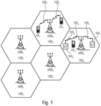
- Fig. 1 is a schematic representation of an example of such a network infrastructure, like a wireless communication system including a plurality of base stations eNB 1 to eNB 5 , each serving a specific area surrounding the base station schematically represented by the respective cells 100 1 to 100 5 .
- the base stations are provided to serve users within a cell.
- a user may be a stationary device or a mobile device.
- the wireless communication system may be accessed by loT devices which connect to a base station or to a user.
- Fig. 1 shows an exemplary view of only five cells, however, the wireless communication system may include more such cells.
- Fig. 1 shows two users UE 1 and UE 2 , also referred to as user equipment (UE), that are in cell 100 2 and that are served by base station eNB 2 .
- Another user UE 3 is shown in cell 100 4 which is served by base station eNB 4 .
- the arrows 102, 102 2 and 102 3 schematically represent uplink/downlink connections for transmitting data from a user UE 1 , UE 2 and UE 3 to the base stations eNB 2 , eNB 4 or for transmitting data from the base stations eNB 2 , eNB 4 to the users UE 1 , UE 2 , UE 3 .
- Fig. 1 shows two users UE 1 and UE 2 , also referred to as user equipment (UE), that are in cell 100 2 and that are served by base station eNB 2 .
- Another user UE 3 is shown in cell 100 4
- loT device 104 accesses the wireless communication system via the base station eNB 4 to receive and transmit data as schematically represented by arrow 105 1 .
- the loT device 104 2 accesses the wireless communication system via the user UE 3 as is schematically represented by arrow 105 2 .
- the wireless communication system may be any single-tone or multicarrier system based on frequency-division multiplexing, like the orthogonal frequency-division multiplexing (OFDM) system, the orthogonal frequency-division multiple access (OFDMA) system defined by the LTE standard, or any other IFFT-based signal with or without CP, e.g. DFT-s-OFDM.
- OFDM orthogonal frequency-division multiplexing
- OFDMA orthogonal frequency-division multiple access
- Other waveforms like non-orthogonal waveforms for multiple access, e.g. filter-bank multicarrier (FBMC), may be used.
- FBMC filter-bank multicarrier
- Standard LTE devices like the users UE 1 , UE 2 , UE 3 , operate within a first bandwidth, and the loT devices 104 1 and 104 2 operate within a second bandwidth which is narrower than the first bandwidth.
- the second bandwidth may be defined in accordance with the NB-loT enhancement of the LTE Rel. 13 standard, referred to in the following also as NB-loT.
- a wireless communication system operating in accordance with the LTE standard may have a system bandwidth of 1.4 MHz, 3.0 MHz, 5 MHz, 10 MHz, 15 MHz, 20 MHz or aggregated system bandwidth consisting of any combination of these, and the bandwidth in accordance with the NB-loT enhancement of the LTE Rel. 13 standard may be by 200 kHz.
- An OFDMA system for data transmission may include an OFDMA-based physical resource grid which comprises plurality of physical resource blocks (PRBs) each defined by 12 subcarriers by 7 OFDM symbols and including a set of resource elements to which various physical channels and physical signals are mapped.
- a resource element is made up of one symbol in the time domain and one subcarrier in the frequency domain.
- PRBs physical resource blocks
- a system bandwidth of 1.4 MHz includes 6 PRBs
- the 200 kHz bandwidth in accordance with the NB-loT enhancement of the LTE Rel. 13 standard includes 1 PRB.
- the physical channels may include the physical downlink shared channel (PDSCH) including user specific data, also referred to as downlink payload data, the physical broadcast channel (PBCH) including for example the master information block (MIB) or the system information block (SIB), the physical downlink control channel (PDCCH) including for example the downlink control information (DCI), etc.
- the physical signals may comprise reference signals (RS), synchronization signals and the like.
- the LTE resource grid comprises a 10 ms frame in the time domain having a certain bandwidth in the frequency domain, e.g. 1.4 MHz.
- the frame has 10 subframes of 1 ms length, and each subframe includes two slots of 6 or 7 OFDM symbols depending on the cyclic prefix (CP) length.
- CP cyclic prefix
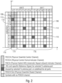
- Fig. 2 shows an exemplary LTE OFDMA-based subframe with two antenna ports for different selected Tx antenna ports.
- the subframe includes two resource blocks (RB) each made up of one slot of the subframe and 12 subcarriers in the frequency domain.
- the subcarriers in the frequency domain are shown as subcarrier 0 to subcarrier 11, and in the time domain, each slot includes 7 OFDM symbols, e.g. in the slot 0 OFDM symbols 0 to 6 and in slot 1 OFDM symbols 7 to 13.
- the white boxes 106 represent resource elements allocated to the PDSCH including the payload or user data, also referred to a payload region.
- the resource elements for the physical control channels (including non-payload or non-user data), also referred to the control region, are represented by the hatched boxes 108.
- resource elements 108 may be allocated to the PDCCH, to the physical control format indicator channel (PCFICH), and to the physical hybrid ARQ indicator channel (PHICH).
- the cross-hatched boxes 110 represent resource elements which are allocated to the RS that may be used for the channel estimation.
- the black boxes 112 represent unused resources in the current antenna port that may correspond to RSs in another antenna port.
- the resource elements 108, 110, 112 allocated to the physical control channels and to the physical reference signals are not evenly distributed over time.
- the resource elements associated with the symbol 0 and the symbol 1 are allocated to the physical control channels or to the physical reference signals, no resource elements in the symbols 0 and 1 are allocated to payload data.
- the resource elements associated with symbol 4 in slot 0 as well as the resource elements associated with symbols 7 and 11 in slot 1 of the subframe are allocated in part to the physical control channels or to the physical reference signals.
- the white resource elements shown in Fig. 2 may include symbols associated with payload data or user data and in the slot 0 for symbols 2, 3, 5 and 6, all resource elements 106 may be allocated to payload data, while less resource elements 106 are allocated to payload data in symbol 4 of slot 0, and no resource element is allocated to payload data in symbols 0 and 1.
- the resource elements associated with symbols 8, 9, 10, 12 and 13 are all allocated to payload data, while for symbols 7 and 11 less resource elements are allocated to payload data.
- Fig. 3 shows an example for time units that may be used for the downlink in accordance with the NB-loT.
- NB-loT may operate within a 200 kHz bandwidth, which corresponds to 12 subcarriers or 1 physical resource block (PRB) in frequency domain.
- the downlink may be based on orthogonal frequency division multiple access (OFDMA) and may have the same subcarrier spacing, the same OFDM symbol duration, the same slot format, the same slot duration, and the same subframe duration as defined by the LTE standard.
- OFDMA orthogonal frequency division multiple access
- the uplink may be based on SC-FDMA (Single Carrier Frequency Division Multiple Access) including a single-tone transmission per user equipment, as a special case of SC-FDMA.
- SC-FDMA Single Carrier Frequency Division Multiple Access
- PAPR Peak-to-Average Power Ratio
- Fig. 3 shows a NB-loT radio frame referred as M-frame and having a length of 60ms.
- M-frame includes 10 M-subframes 200 each having a duration of 6 ms.
- Each M-subframe comprises 6 consecutive subframes 202, each subframe having a length of 1 ms.
- Each subframe 202 has a structure as shown in Fig. 2 and includes two slots 204, each slot including 7 symbols 206, each symbol including the actual signal and a cyclic prefix.
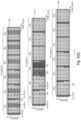
- Fig. 4(a) shows an example of the first three M-subframes 200 0 , 200, and 200 2 of the M-frame of Fig. 3 .
- the minimum scheduling unit is 1 PRB (1 ms x 180 kHz).
- up to 6 users or devices may be scheduled in one of the M-subframes (one user per subframe).
- a transport block is mapped to the scheduling units (PRBs) assigned to the user in one M-subframe.
- PRBs scheduling units
- NB-loT applies a time expansion approach to spread the scheduling units in time dimension.
- Fig. 4(a) further shows how NB-loT resource elements are mapped to the respective LTE downlink physical channels and physical signals.
- LTE also NB-loT may include the following LTE physical channels:
- Each of the M-subframes includes 6 subframes 202 0 to 202 5 having a structure similar to that described above with reference to Fig. 2 .
- the LTE physical channels and physical signals are distributed as depicted in Fig. 4(a) .
- Each of the subframes 202 0 to 202 5 in the first M-subframe 200 0 includes at the beginning resource elements defined by the first OFDM symbol and the 12 subcarriers which are mapped to the M-PDCCH.
- Each subframe may further include resource elements mapped to the M-PBCH, to the M-PDSCH, as well as resource elements mapped to the reference signals CRS.
- the second M-subframe 200 also includes 6 subframes 202 0 to 202 5 , each subframe including resource elements at the first OFDM symbol mapped to the M-PDCCH. Further, each of the subframes includes resource elements mapped to the reference signals CRS.
- subframes 202 0 , 202 1 , 202 3 , 202 4 and 202 5 substantially all of the resource elements are mapped to the M-PDSCH, except for those resource elements mapped to M-PDCCH and the mapped to the reference signals CRS.
- the subframe 202 2 substantially all resource elements are mapped to the M-PSCH including the secondary and primary synchronization signals, except for those resource elements mapped to M-PDCCH and the mapped to the reference signals CRS.
- the third M-subframe 200 2 also 6 subframes 202 0 to 202 5 are provided all including resource elements being mapped to the M-PDSCH, except for those resource elements mapped to M-PDCCH and the mapped to the reference signals CRS.
- the remaining M-subframes 200s to 200 9 forming the M-frame shown in Fig. 3 are not shown in Fig. 4(a) .
- Fig. 4(b) shows all M-subframes 200 0 to 200 9 of a M-frame.
- M-subframes 200 4 , 200 5 , 200 7 and 200 9 have the same structure as the third M-subframe 202 2 , i.e., include, besides the control information in the first resource elements and the reference signals only resource elements mapped to the M-PDSCH.
- M-subframes 200 3 , 200 6 and 200 8 have substantially the same structure as the second M-subframe 200 1 , except that in M-subframes 200 3 and 200 8 the primary and secondary synchronization signals are in the last subframe 202 5 .
- the resource elements are mapped to the M-PBCH, however no resource elements are mapped or allocated to the M-PBCH in second and third M-subframes 202, and 202 2 .
- the primary and secondary synchronization signals PSS and SSS of the M-PSCH are transmitted in the second, fourth, seventh and ninth M-subframes 200 1 , 200 3 , 200 6 and 200 8 but not in first M-subframe 200 0 and also not in any of the M-subframes 200 2 , 200 4 , 200 5 , 200 7 and 200 9 following the second M-subframe 200 1 .
- the PSS and SSS are arranged in continuous OFDM symbols (see the symbols 206 in Fig. 4(b) ).
- the M-PDCCH is distributed across the M-subframes, more specifically in the example of Fig. 4(a) and Fig. 4(b) , resource elements at the first OFDM symbol in each M-subframe are mapped to the M-PDCCH.
- a forward scheduling method may be used for NB-loT, and the M-PDCCH scheduling information given in a M-subframe may be applicable to M-PDSCH that starts at least one M-subframe later.
- Fig. 5 is a schematic representation of the different operating modes in accordance with NB-loT, also referred to as the NB-loT.
- Fig. 5(a) shows the in-band LTE operation mode in accordance with which a NB-loT carrier or frequency band 300, also referred to as a NB-loT channel, is deployed within the LTE carrier or frequency band 301.
- Fig. 5(b) shows the standalone GSM operation mode placing the NB-loT frequency band 300 among a plurality of GSM carriers 302.
- the NB-loT frequency band 300 is separated by a guard band from the GSM carriers.
- Fig. 5(c) shows the LTE guard band operation mode, in accordance with which the NB-loT carrier 300 is placed in one of the LTE guard bands provided at both ends of the carrier of the standard LTE.
- a receiver operating in accordance with NB-loT needs to establish a connection with a wireless communication network, like the one depicted in Fig. 1 , to receive or send information.
- the receiver is tuned to listen to the NB-loT frequency band to find the primary synchronization signal PSS and the secondary synchronization signal SSS which allow the receiver to synchronize on a subframe level and to obtain a physical layer cell identity group number.
- the receiver will proceed to read system information, e.g. from the master information block (MIB) provided in the M-PBCH.
- MIB master information block
- the sixth shows the distribution of the M-subframes including information for establishing a connection over a plurality of M-frames.
- the first M-subframes 200 0 are provided at the beginning of each M-frame, followed by the second M-subframes 200 1 .
- PSS and SSS are received on average every 15 ms, and occur 4 times within a 60ms M-frame (see Fig. 3 and Fig. 4 ).
- the system information is transported in parts of every M-subframe 0 in each M-frame via M-PBCH every 60 ms, which has a transmission time interval (TTI) of 240 ms.
- TTI transmission time interval
- establishing a connection of a receiver, like an loT device, operating in accordance with NB-loT may be delayed as the remaining M-subframes 200 2 to 200 9 do not include any resource elements mapped to connection and system information.
- the 6 PRBs in the M-frame need to be shared among the loT devices which may lead to further delays when receiving/transmitting data.
- synchronization, random access and activity time when connecting and transmitting on a NB-loT channel or a NB-loT frequency band may be quite high.
- each of the channels has the same structure.
- Fig. 7 is a schematic representation of a radio transmission between a transmitter 210 and a receiver 212 of a wireless communication network described above with reference to Fig. 1 .
- the transmitter 210 may be a base station eNB or a user equipment, and the receiver 212 may be an loT device or another user equipment operating in accordance with the NB-loT.
- the receiver 212 includes a receiving section 214 and a transmitting section 216 both coupled to an antenna 218.
- the receiver 212 via the antenna 218, receives a radio signal from the transmitter 210, and the radio signal is indicated in Fig. 7 at 220.
- the radio signal includes a first frequency band SC, also referred to as a first channel or first carrier, and a second frequency band D1, also referred to as a second channel or second carrier.
- Each of the frequency bands SC, D1 include or carry a signal.
- the first frequency band SC includes a first signal 222 having a plurality of M-frames 226 n-1 , 226 n and 226 n+1 .
- the second frequency band D1 includes a second signal 224 having a plurality of M-frames 228 n-1 , 228 n and 228 n+1 .
- the first signal may be a legacy LTE Rel. 13 NB-loT carrier which supports legacy users.
- the first signal may transport new system information for new users with a reference to a second/third/fourth narrowband carrier as described herein.
- the number of M-frames may be more or less than those depicted in Fig. 7 .
- Each of the M-frames includes 10 M-subframes, each of which has a structure as explained above with reference to Figs. 2 and 3 , i.e., each subframe, in accordance with the depicted embodiment, includes a plurality of resource symbols defined by one of the subcarriers and one of the OFDM symbols.
- the first resource elements in each M-subframe are mapped or allocated to control information in the M-PDCCH, and the other resource elements are mapped to at least one of the M-PBCH, the M-PSCH, the M-PDSCH, the or M-PUSCH (Physical Uplink Shared CHannel) or the M-RACH (Random Access CHannel), in accordance with the inventive approach, at least one of the signals in the first and second frequency bands SC, D1 is dedicated to single or multiple pre-defined functionalities.
- the M-subframes of the first signal 222 may include connecting information, like the above referenced synchronization channel including the primary and/or secondary synchronization signals and system information, whereas the second signal 224 has subframes all of which are free of any connecting information.
- the receiver 212 processes the received radio signal 220 and listens to the first frequency band SC in which the first signal 222 is transmitted to receive the connecting information allowing the receiver 212 to establish a connection with the wireless communication network by setting up, for example, a radio communication with the transmitter 210.
- connecting information allowing the receiver 212 to establish a connection to the communication network is provided not provided in the second signal 224 in the second frequency band D1, so that any receiver listening not to the first frequency band SC, is not in a position to set up a connection with the transmitter 210. Only once the necessary connecting information has been obtained will the receiver also be informed, by the band information, about the second frequency band D1 to be used for receiving/transmitting further information or data.
- the connecting information may be placed within the M-subframes of the first signal 222 at shorter intervals than in the above described prior art approach allowing for a synchronization of the receiver 212 with the wireless communication network with a reduced delay.
- resource elements may be mapped to the connecting information.
- resource elements in the M-subframes of the first signal 222 are mapped to band information indicating the second frequency band D1 including the second signal 224.
- the receiver 212 after having synchronized with and established the connection to the communication system, on the basis of the band information, operates in the second frequency band D1, i.e., the receiving section 214 processes the second signal 224, for example by tuning the receiving section 214 on the basis of the band information from the first frequency band SC to the second frequency band D1.
- the receiving section 214 may be operated so as to listen simultaneously to the first and second frequency bands SC, D1, and once the connection with the wireless communication network has been established, the second signal 224 in the second frequency band D1 will be processed.
- the receiving section 214 may be operated in a full duplex mode, rather than in the just described half-duplex mode, so as to listen to one or more carriers while transmitting on one or more other carriers.
- Base stations in NR may also transmit and receive on the same frequency in a full-duplex mode.
- the second signal 224 may the M-PDCCH as well as resource elements mapped to the M-PDSCH, M-PUSCH and M-RACH.
- the receiver 212 After being directed from the first signal 222 to the second signal 224, the receiver 212 operates in accordance with the control information received on the second signal, performs the steps for accessing the network using the M-RACH, and receives/transmits data on the resource elements provided in the M-PDSCH and the M-PUSCH.
- the inventive approach allows mapping single or multiple pre-defined functionalities onto one or more NB-loT frequency bands or channels, each having, for example, a bandwidth of 200 kHz.
- the inventive approach allows aggregating several of the 200 kHz carriers (bands) for the same functionality. For example, if the NB-loT carrier is allocated inside the LTE guard band (see Fig. 5(c) above), two NB-loT carriers may be utilized, the one on the right and the one on the left of the LTE component carrier. These guard band NB-loT carriers may be operated simultaneously to the "normal" LTE band and may provide additional information or more robust information for UEs operating as a narrowband or broadband device. Further, additional information may be provided. Furthermore, NB-loT carriers can be allocated and aggregated in the duplex gap between a downlink and uplink FDD component carrier, e.g. in a LTE or UMTS FDD system.
- the first frequency band SC including the first signal 222 may be dedicated to include, together with the band information, only synchronization channel information and broadcast information needed for setting up a connection to the wireless communication network, for example, the M-PSCH and The M-SSCH including the primary and/or secondary synchronization signals PSS, SSS and the broadcast channel M-PBCH.
- the second signal 224 may be a dedicated channel including one or more of system information, control information (M-PDCCH), the M-PDSCH, the M-PUSCH or the M-RACH.
- more than two frequency bands may be used, for example, a third frequency band and fourth frequency band including a third signal and a fourth signal, respectively, which are dedicated signals including only one of the above information.
- related channels may be combined, for example channels related to a specific user so that, for example, the second signal 224 includes data and control messages for the specific receiver 212.
- channels related to the transmission may be combined, for example, the first signal 222 may be used for synchronization, system information and control information transmission as well as for providing the M-PDSCH, whereas the second signal 224 is used for the uplink only, like the M-RACH and the PUSCH.
- a load balancing approach may be provided, in accordance with which the system information or band information in the first signal 222 indicate to different receivers the second frequency band D1 or a third and fourth frequency band to be used by the specific receiver for obtaining control information and random access channel information, thereby balancing the traffic in the respective bands or channels.
- specific receivers 212 like loT devices providing alerts, may be signaled a frequency band that is reserved for the communication with such kinds of devices.
- the system information may randomly assign the second, third or fourth frequency bands for a receiver 212 connecting to the network, thereby providing random choice. A weighted random choice may also be provided.
- one of the frequency bands may be used as an anchor channel, may provide hopping sequence information or a reconfiguration message for the receiver 212.
- Fig. 8 shows an embodiment of the inventive approach in which the radio signal includes three frequency bands or channels SC, D1, D2, one channel SC dedicated to include synchronization information, system information and control channel information, and the other channels D1, D2 dedicated to the downlink shared data channel.
- Fig. 8(a) shows a conventional approach
- Fig. 8(b) shows details of the inventive approach.
- Fig. 8(a) shows three channels or frequency bands C1-C3 operating in accordance with the conventional NB-loT.
- Each channel has the same structure in that the first M-frame subframes 200 0 , besides the M-PDCCH and the M-PDSCH also includes the M-PBCH.
- the subsequent M-subframes do not include the broadcast information and only the second M-subframe 200, includes the M-PSCH.
- the structure of each of the channels C1-C3 corresponds to the one shown in Fig. 4 .
- each of the channels C1-C3 includes information covering the entire functionality to be provided to a receiver.
- Fig. 8(b) shows an embodiment in accordance with the inventive approach mapping single or multiple pre-defined functionalities onto several NB-loT bands or channels. Like in Fig. 8(a) three frequency bands or channels SC, D1, D2 for serving an loT device are used.
- each of the frequency bands SC, D1, D2 is a dedicated frequency band or channel.
- the first channel SC may be referred to as a synchronization channel and, other than in Fig. 8(a) , the first channel SC includes in each M-subframe 200 0 -200 2 the M-PSCH and the M-PBCH. Further the PDCCH is provided in each of the M-subframes 200 0 -200 2 .
- the receiver 212 (see Fig.
- the first signal in the synchronization channel SC is such that one or more of the M-subframes of each M-frame includes connecting information allowing to make a connection to the network.
- the synchronization channel may only include, in each M-subframe, the connecting information together with the band information informing the receiver about the further frequency bands that are available.
- the connecting information may be transmitted continuously in each M-subframe or may be transmitted intermittently, e.g., in n th M-subframe.
- the transmitter is a battery operated device, e.g., another UE, the synchronization information is only sent out at specific times so as to reduce the energy consumption at the transmitter.
- the second and third frequency bands D1, D2 or channels D1, D2 are dedicated to the M-PDSCH, and neither of the sub-frames of the second and third signal 224, 230 in the second and third frequency band D1, D2 includes any connecting information.
- the receiver tunes to one of the frequency bands D1, D2 or both of the frequency bands D1, D2 so as to receive and process data provided on these channels D1, D2 in the downlink.
- a further channels may be added, e.g. a channel having resource elements mapped only to the M-PDCCH or an additional synchronization channel.
- Another advantage of the inventive approach is that, due to providing the synchronization and system information in the dedicated synchronization band SC, the cell search procedure at the receiver 212 is faster and less complex. For example, to improve the access proves, a dedicated channel for the M-RACH may be used, thereby speeding up the random access procedure.
- Yet another advantage of the inventive approach is that it scales. For example, 1..n of the available frequency bands or channels may be aggregated in the frequency domain, also referred to as NB-loT carrier aggregation, and in case additional capacities are needed, additional channels may be introduced.
- using the synchronization channel SC or using more than one of these synchronization channels provides the synchronization information with at least basic system information pointing, for example, to further system information on a different channel.
- further information is transmitted on this channel.
- data may also be transmitted on this channel as well.
- the system information includes the necessary information about the cell, for example the FFT size, etc., and the position of further channels and the function of these further channels.
- control data may be split onto several frequency bands which may allow for a better resource utilization of the control channels.
- the basic system parameters may include the cell ID, an operation mode, a position of further NB-loT channels or LTE bands and an access barring flag.
- SIB system information block
- the channels D1, D2, as depicted in Fig. 8(b) may be dedicated DL data channels on which DL data is transmitted and the loT device jumps to the respective band after receiving a DL grant.
- the channels D1, D2 are signaled to the loT device by the system information.
- these channels may be used by non-loT devices, for example, LTE users in case no loT devices are scheduled for these bands.
- the above mentioned system information in accordance with embodiments, may also advertise channels having remaining capacity or advertise a priority/likelihood of a UE choosing such a channel. Additionally, the channels may be advertised for certain UE groups or special functions, for example emergency M-RACH to allow specific devices which need to set up a connection to the system immediately to use these cases.
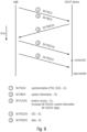
- Fig. 9 shows an example for connecting a receiver to the communication network, more specifically to a base station thereof, using an NB-loT system in accordance with the inventive approach using dedicated frequency bands, for example a system as shown in Fig. 8(b) including additional bands for the random access channel and for the control channel.
- the UE initially, searches 1 channels for PSS and SSS signals which are used also for an initial time and frequency synchronization. Having received such synchronization signals, the UE decodes 2 system information from the M-PBCH, for example the M-RACH to M-PDCCH mapping.
- access barring and/or special channels for high priority/emergency access may be signaled.
- the random access is performed 3 on the band i specified in the system or band information, and the UE decodes 4 the control information on the M-PDCCH on band j depending on the above mentioned M-RACH to M-PDCCH mapping which completes the connection process.
- the loT device is connected to the communication network. Data may now be transmitted 5 in the M-PDSCH which may be provided on a separate frequency band as indicated, either by the control information or by the system information.
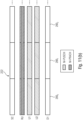
- Fig. 10 shows an example of the above mentioned M-RACH to M-PDCCH mapping in a system with 1... N M-RACH channels and 1... K M-PDCCH channels, wherein N may be larger, smaller or equal to K.
- a predefined M-PDCCH of the original RACH may be used for the initial RACH response and, after the initial random access, a particular user may be assigned to a different control channel.
- This mapping may be stored at the receiver or may be broadcast using the M-PBCH in case other UEs require this information.
- Fig. 10 shows an example of N M-RACH and K M-PDCCH channels, each of which may be transmitted in a dedicated frequency band.
- each of the channels 1..N and 1..K may be dedicated channels including only the M-PARCH or the M-PDCCH.
- the mapping information provided by the M-PBCH may only indicate the frequency band where to find the control information.
- the respective channels may also include other information, and the respective random access information and control information may be placed at specific positions within the channel.
- the mapping information provided by the M-PBCH may indicate the frequency band where to find the control information and a location within the respective frequency band, for example what resource elements within a M-subframe are allocated to the control information.
- each band may have a dedicated M-RACH response channel (M-PDCCH) or a dedicated M-RACH sequence may depend on the control channel the UE is listening to.
- M-PDCCH M-RACH response channel
- Fig. 11 shows an example of an NB-loT system using a dedicated M-RACH channel.
- Fig. 11(a) shows a conventional approach for signaling the M-RACH channel
- Fig. 11(b) shows the signaling in accordance with the inventive approach.
- Fig. 11(a) three frequency bands or channels C1 to C3 are shown, and the M-RACH are provided in the first and second M-subframes 200 0 and 200 1 .
- the following M-frames are provided for the M-PUSCH.
- Fig. 11(b) in addition to the synchronization channel SC as explained above with reference to Fig. 8 and in addition to the channel D1 not including any connecting information, further channels or frequency bands RU, U1, U2 are provided which may also not include connecting information.
- a narrowband carrier of a frequency band RU is provided for the random access information, and additional uplink channels U1, U2 are provided on separate carriers or frequency bands.
- each narrowband carrier C1-C3 has on each narrowband carrier C1-C3 its own M-RACH and UL resources, in accordance with the inventive approach, the resources are reorganized to enable a constant random access on the dedicated channel RU while the additional channels U1 and U2 provide additional uplink resources.
- the M-RACH and UL resources in the conventional approach of Fig. 11(a) may be reorganized in a different way such that in each channel C1-C3 the UL resources and the random access resources are kept in the same channel.
- the random access slots do not start at the same time but are shifted.
- Fig. 12 describes embodiments for shifted random access slots by reorganizing the resources in a way as described above.
- Fig. 12(a) shows a conventional arrangement of the random access sequence in a NB-loT signal.
- the random access information is synchronized among the channels and occurs in each channel at the same time at an interval ⁇ t 1 .
- this synchronization is avoided. Rather, as is shown in Fig. 12(b) , within the respective channels C1-C3, the random access information is shifted with respect to each other so that the interval ⁇ t 2 between the random access slots is shorter than the interval ⁇ t 1 in the conventional approach, thereby allowing the access time to be reduced, for example for an loT device that is capable of listening to each of the frequency bands C1-C3.
- Fig. 12(c) shows another embodiment of the inventive approach allowing for a reduced signaling by the transmitter providing the signals in the frequency bands C1 to C3.
- the random access slot is signaled when observing all three channels with the same time interval ⁇ t 1 .
- the first random access slot is signaled on the first carrier
- the second one is signaled on the second carrier
- third one is signaled in the third carrier.
- the next, fourth random access slot is again signaled in the first carrier. This reduces the signaling in each channel required by the transmitter.
- function specific narrowband channels allow simple (low complexity) receivers to run on a single narrowband channel at a time.
- the receiver module of the receiver may provide for a half-duplex operation, i.e., allows operating on a single frequency band at one time.
- more complex devices may be provided, for example receivers operating in a carrier aggregation or wideband reception mode allowing to receive data on multiple frequency bands, so as to aggregate several of the above described narrowband channels or even combinations of standard LTE channels and narrowband channels. This aggregation allows such devices to synchronize faster and to have higher transmission rates as well as to simultaneously receive control and user data.
- More complex transceivers may operate in a full-duplex mode with simultaneous transmission and reception of one or several narrowband carriers.
- Fig. 13 shows a schematic view of a narrowband loT system using six frequency bands or channels and how devices having different receiving modules make use of the respective channels.
- the first channel is a synchronization channel transmitting at least the information PSS and SSS.
- the second channel is a data channel and the third channel is a control channel.
- the fourth channel again, is a synchronization channel, and the fifth and sixth channels are, again, data channels.
- the second, third, fifth and sixth channels are dedicated channels that, in accordance with embodiments, do not include any information allowing a receiver to connect to the communication network.
- Fig. 13 shows a schematic view of a narrowband loT system using six frequency bands or channels and how devices having different receiving modules make use of the respective channels.
- the first channel is a synchronization channel transmitting at least the information PSS and SSS.
- the second channel is a data channel and the third channel is a control channel.
- the fourth channel again, is a synchronization channel
- the fifth and sixth channels are
- the signals transmitted in the respective frequency bands 1 to 6 are, in frequency bands 1 and 4, the connecting information and band information and the remaining frequency bands 2, 3, 5 and 6 include data and control information but are free of any connecting information so that a receiver listening to bands 2, 3, 5 and 6 cannot set up a connection to the communication network.
- the 200 kHz receiver initially listens to frequency band 1 to receive the connecting information and band information. Once the receiver connected to the communication network, on the basis of the band information in frequency band 1, the receiving module is tuned to the frequency band 3 to derive control information for operating the receiver.
- the control information includes further band information controlling the receiver to switch the receiving module to the frequency band 2 to receive or send data.
- Fig. 13 further shows a 400 kHz device which is able to listen to two frequency bands simultaneously and the device is tuned to listen simultaneously to two adjacent frequency bands 3 and 4 initially so as to obtain the connecting information as well as the control information and, on the basis of the band information, the receiver may be tuned to the frequency bands 5 and 6 so as to receive/transmit data on these bands.
- a further device shown in Fig. 13 is a 800 kHz device simultaneously listening to four frequency bands 1 to 4 of which bands 1 and 4 include connecting information which allows for a faster connection of such a device as information for connecting from both synchronization bands 1 and 4 may be used.
- Control information is found on band 3, is signaled by the synchronization bands, and data may be sent/received on band 2.
- the 400 kHz and 800 kHz devices are shown to listen to adjacent frequency bands which may be achieved by an appropriate broadband receiver.
- the 400 kHz and 800 kHz devices may include separate narrowband receivers listening only to one frequency band and operated simultaneously, and when tuning the respective narrowband receiver modules to adjacent frequency bands, a listening scheme as shown in Fig. 13 may be achieved.
- the 400 kHz and 800 kHz devices may operate on non-adjacent frequency bands, for example by tuning separate narrowband or broadband receivers to different frequencies so that, for example, in case of the 400 kHz device, a first narrowband receiving module may listen to the frequency band 1 for obtaining the connecting information and a second receiving module listens to the frequency band 3 to obtain the control information.
- the 800 kHz device may listen to separate frequency bands.
- the UE has a wideband transmitter, or in case it has several narrowband transmitters, it may use several bands simultaneously, which may also be adjacent bands, as frequency bands 5 and 6 in Fig. 13 which allows for a higher data rate in the uplink. Further, by hopping between several channels in the downlink and uplink, a frequency diversity may be achieved.
- the lower two data channels 5 and 6 may be dynamically shared between the narrowband loT and LTE users.
- Embodiments of the present invention may be implemented in a wireless communication system as depicted in Fig. 1 including base stations, users, like mobile terminals, and loT devices.
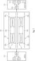
- Fig. 14 is a schematic representation of a wireless communication system 250 for transmitting information from a transmitter TX to a receiver RX.
- the transmitter TX includes at least one antenna ANT TX and the receiver RX includes at least one antenna ANT RX .
- the transmitter TX and/or the receiver RX may include more than one antenna to implement a MIMO, SIMO or MISO.
- signals are transmitted between the transmitter TX and the receiver RX via a wireless communication link, like a radio link.
- the transmission may be in accordance with the OFDMA communication approach.
- the signaling between the transmitter TX and RX is in accordance with the above described embodiments of the present invention
- the receiver RX receives via the antenna the radio signal from the transmitter TX and applies the signal to the OFDMA demodulator 254 including a signal processor 256 for processing the radio signal.
- the radio signal has at least a first frequency band SC and a second frequency band D1.
- the first frequency band SC includes a first signal
- the second frequency band D1 includes a second signal
- each of the first signal and the second signal has a plurality of frames, each frame having a plurality of subframes.
- One or more of the subframes of the first signal comprise connecting information allowing the receiver to establish a connection with the wireless communication system and band information indicating the second frequency band D1.
- the receiver RX establishes a connection with the wireless communication system using the connecting information, and, after having established the connection with the wireless communication system and responsive to the band information, operates in the second frequency band D1.
- the transmitter TX comprises an OFDMA modulator 258 comprising a signal processor 260 to generate a signal to be transmitted to the receiver RX.
- the transmitter TX may transmit a radio signal having at least a first frequency band SC and a second frequency band D1.
- the first frequency band SC includes a first signal
- the second frequency band D1 includes a second signal
- each of the first signal and the second signal has a plurality of frames with each frame having a plurality of subframes.
- One or more of the subframes of the first signal comprises connecting information allowing the receiver RX to establish a connection with the wireless communication system and band information indicating the second frequency band D1. All of the subframes of the second signal are free of any connecting information.
- the transmitter includes the OFDMA modulator operating so as allocate the connecting information and the band information as well as other information in the subframes in the respective frequency bands.
- Fig. 15 is a block diagram of a transmitter 300 in a wireless communication system for transmitting a radio signal to a receiver in accordance with the embodiments described above.
- the transmitter 300 receives data 302 that is encoded by the channel encoder 304, modulated by the modulator 306 and mapped to the multiple carriers or frequency bands by the mapper 308.
- Control signals 314 are provided by the control channel unit 316 and the control mapper 318, pilot symbols 320 are provided by the pilot symbol generator 322, and PSS/SSS signals 324 are provided from the PSS/SSS signal generator 326.
- the signals are combined by the combiner 312 such that a first signal to be transmitted in a first frequency band SC is provided , and such that a second signal to be transmitted in a second frequency band D1 is provided.
- the signals are combined such that the first signal has one or more subframes including connecting information allowing a receiver to establish a connection with the wireless communication system and band information indicating the second frequency band D1, and such that all of the subframes of the second signal are free of any connecting information.
- the combined signals 328 are provided to the IFFT+CP block 330, and are converted by the DAC 332 into the analog domain.
- the analog signal 336 is processed for radio transmission and eventually transmitted by the antenna 338.
- a first aspect relates to a receiver, wherein the receiver UE 1 -UE 3 , 104 1 -104 2 , 212, RX is configured to receive and process a radio signal 220, the radio signal 220 comprising at least a first frequency band SC and a second frequency band D1, the first frequency band SC including a first signal 222, the second frequency band D1 including a second signal 224, and each of the first signal 222 and the second signal 224 comprising a plurality of frames 226, M-frame, each frame 226, M-frame having a plurality of subframes 200, M-subframe, wherein one or more of the subframes 200, M-subframe of the first signal 222 comprises connecting information allowing a receiver UE 1 -UE 3 , 104 1 -104 2 , 212, RX to establish a connection with a wireless communication system, wherein all of the subframes 200, M-subframe of the second signal 224 are free of any connecting information, and wherein the receiver UE 1 -UE
- each subframe 200, M-subframe of the first signal 222 comprises the connecting information.
- the connecting information comprises synchronization information M-PSCH, M-SSCH and/or system information M-PBCH.
- one or more of the subframes 200, M-subframe of the first signal 222 further comprises one or more of: a region for a control channel M-PDCCH, the receiver UE 1 -UE 3 , 104 1 -104 2 , 212, RX configured to control an operation of the receiver UE 1 -UE 3 , 104 1 -104 2 , 212, RX and/or a communication with the wireless communication system using information in the control channel, a region for a random access channel M-RACH, a region for a downlink channel M-PDSCH, and/or a region for an uplink channel M-PUSCH, and/or a region for an uplink control channel M-PUCCH, and/ or a region for a multicast DL or UL channel.
- a region for a control channel M-PDCCH the receiver UE 1 -UE 3 , 104 1 -104 2 , 212
- RX configured to control an operation of the receiver UE 1 -UE 3 ,
- the radio signal 220 comprises a third frequency band, the third frequency band including the first signal 222.
- the radio signal 220 comprises a fourth frequency band, the fourth frequency band including the second signal 224.
- the second signal 224 in the second frequency band D1 includes further band information system information indicating the fourth frequency band, the receiver UE 1 -UE 3 , 104 1 -104 2 , 212, RX configured to operate in the second frequency band D1 responsive to the further band information.
- the band information indicates for a certain receiver UE 1 -UE 3 , 104 1 -104 2 , 212, RX the second and fourth radio frequency bands dependent on a capacity on the respective bands, dependent on the kind of receiver UE 1 -UE 3 , 104 1 -104 2 , 212, RX, dependent on a certain function provided by a receiver UE 1 -UE 3 , 104 1 -104 2 , 212, RX, or dependent on a message type carried over a receiver UE 1 -UE 3 , 104 1 -104 2 , 212, RX, e.g. prioritized messages used for signaling emergency information.
- the receiver is configured to hop between the plurality of frequency bands.
- one or more of the subframes 200, M-subframe of the second signal 224 comprises one or more of a region for a control channel M-PDCCH, the receiver UE 1 -UE 3 , 104 1 -104 2 , 212, RX configured to control an operation of the receiver UE 1 -UE 3 , 104 1 -104 2 , 212, RX and/or a communication with the wireless communication system using information in the control channel, a region for a random access channel M-RACH, a region for a downlink channel M-PDSCH, a region for an uplink channel M-PUSCH and/or a region for a multicast DL or UL channel.
- all of the subframes 200, M-subframe of the second signal 224 comprises only the region for a control channel M-PDCCH, only the region for a random access channel M-RACH, only the region for a downlink channel M-PDSCH, only the region for an uplink channel M-PUSCH, or a region for a multicast DL or UL channel.
- the receiver comprises a receiver section 214 configured to receive the first frequency band SC and to be switched from the first frequency band SC to the second frequency band D1 responsive to the system information, the receiver UE 1 -UE 3 , 104 1 -104 2 , 212, RX configured to switch from the first frequency band SC to the second frequency band D1 using the band information.
- the receiver comprises a receiver section 214 configured to simultaneously receive a plurality of frequency bands, and to simultaneously process the first and second signals 222, 224.
- the receiver comprises a transmitter section configured to simultaneously transmit a signal in a plurality of frequency bands.
- the receiver is an loT device
- the wireless communication system is configured to serve non-loT devices and loT devices
- the first and second frequency bands SC, D1 have a bandwidth that is narrower than a bandwidth of a frequency band within which the non-loT devices are operable.
- the wireless communication system uses an IFFT Inverse Fast Fourier Transform based signal.
- the IFFT based signal when referring back to the sixteenth aspect, includes OFDM with CP, DFT-s-OFDM with CP, or IFFT-based waveforms without CP.
- OFDM with CP is used for a downlink transmission
- DFT-s-OFDM with CP or a single tone transmission is used for an uplink transmission.
- the first signal 222 comprises the band information indicating the second frequency band D1.
- a radio signal 220 comprises: at least a first frequency band SC and a second frequency band D1, the first frequency band SC including a first signal 222, the second frequency band D1 including a second signal 224, and each of the first signal 222 and the second signal 224 comprising a plurality of frames 226, M-frame, each frame 226, M-frame having a plurality of subframes 200, M-subframe, wherein one or more of the subframes 200, M-subframe of the first signal 222 comprises connecting information allowing a receiver UE 1 -UE 3 , 104 1 -104 2 , 212, RX to establish a connection with a wireless communication system, and wherein all of the subframes 200, M-subframe of the second signal 224 are free of any connecting information.
- a twenty-first aspect relates to a transmitter, wherein the transmitter is configured to transmit a radio signal 220, the radio signal 220 comprising at least a first frequency band SC and a second frequency band D1, the first frequency band SC including a first signal 222, the second frequency band D1 including a second signal 224, and each of the first signal 222 and the second signal 224 comprising a plurality of frames 226, M-frame, each frame 226, M-frame having a plurality of subframes 200, M-subframe, wherein one or more of the subframes 200, M-subframe of the first signal 222 comprises connecting information allowing a receiver UE 1 -UE 3 , 104 1 -104 2 , 212, RX to establish a connection with a wireless communication system, and wherein all of the subframes 200, M-subframe of the second signal 224 are free of any connecting information.
- a wireless communication system comprises: a receiver UE 1 -UE 3 , 104 1 -104 2 , 212, RX according to one of aspects 1 to 19; and a transmitter according to aspect 21.
- a method comprises: receiving and processing, by a receiver UE 1 -UE 3 , 104 1 -104 2 , 212, RX of a wireless communication system, a radio signal 220, the radio signal 220 comprising at least a first frequency band SC and a second frequency band D1, the first frequency band SC including a first signal 222, the second frequency band D1 including a second signal 224, and each of the first signal 222 and the second signal 224 comprising a plurality of frames 226, M-frame, each frame 226, M-frame having a plurality of subframes 200, M-subframe, wherein one or more of the subframes 200, M-subframe of the first signal 222 comprises connecting information allowing a receiver UE 1 -UE 3 , 104 1 -104 2 , 212, RX to establish a connection with a wireless communication system, and wherein all of the subframes 200, M-subframe of the second signal 224 are free of any connecting information, establishing
- a method comprises: transmitting, by a transmitter of a wireless communication system, a radio signal 220, the radio signal 220 comprising at least a first frequency band SC and a second frequency band D1, the first frequency band SC including a first signal 222, the second frequency band D1 including a second signal 224, and each of the first signal 222 and the second signal 224 comprising a plurality of frames 226, M-frame, each frame 226, M-frame having a plurality of subframes 200, M-subframe, wherein one or more of the subframes 200, M-subframe of the first signal 222 comprises connecting information allowing a receiver UE 1 -UE 3 , 104 1 -104 2 , 212, RX to establish a connection with a wireless communication system, and wherein all of the subframes 200, M-subframe of the second signal 224 are free of any connecting information.
- a method comprises: transmitting, by a transmitter of a wireless communication device, a radio signal 220, the radio signal 220 comprising at least a first frequency band SC and a second frequency band D1, the first frequency band SC including a first signal 222, the second frequency band D1 including a second signal 224, and each of the first signal 222 and the second signal 224 comprising a plurality of frames 226, M-frame, each frame 226, M-frame having a plurality of subframes 200, M-subframe, wherein one or more of the subframes 200, M-subframe of the first signal 222 comprises connecting information allowing a receiver UE 1 -UE 3 , 104 1 -104 2 , 212, RX to establish a connection with a wireless communication system, and wherein all of the subframes 200, M-subframe of the second signal 224 are free of any connecting information, receiving and processing, by a receiver UE 1 -UE 3 , 104 1 -104 2 ,
- a twenty-sixth aspect relates to a non-transitory computer program product comprising a computer readable medium storing instructions which, when executed on a computer, perform the method of one of aspects 23 to 25.
- aspects of the described concept have been described in the context of an apparatus, it is clear that these aspects also represent a description of the corresponding method, where a block or a device corresponds to a method step or a feature of a method step. Analogously, aspects described in the context of a method step also represent a description of a corresponding block or item or feature of a corresponding apparatus.
- embodiments of the invention may be implemented in hardware or in software.
- the implementation may be performed using a digital storage medium, for example cloud storage, a floppy disk, a DVD, a Blue-Ray, a CD, a ROM, a PROM, an EPROM, an EEPROM or a FLASH memory, having electronically readable control signals stored thereon, which cooperate (or are capable of cooperating) with a programmable computer system such that the respective method is performed. Therefore, the digital storage medium may be computer readable.
- Some embodiments according to the invention comprise a data carrier having electronically readable control signals, which are capable of cooperating with a programmable computer system, such that one of the methods described herein is performed.
- embodiments of the present invention may be implemented as a computer program product with a program code, the program code being operative for performing one of the methods when the computer program product runs on a computer.
- the program code may for example be stored on a machine readable carrier.
- inventions comprise the computer program for performing one of the methods described herein, stored on a machine readable carrier.
- an embodiment of the inventive method is, therefore, a computer program having a program code for performing one of the methods described herein, when the computer program runs on a computer.
- a further embodiment of the inventive methods is, therefore, a data carrier (or a digital storage medium, or a computer-readable medium) comprising, recorded thereon, the computer program for performing one of the methods described herein.
- a further embodiment of the inventive method is, therefore, a data stream or a sequence of signals representing the computer program for performing one of the methods described herein. The data stream or the sequence of signals may for example be configured to be transferred via a data communication connection, for example via the Internet.
- a further embodiment comprises a processing means, for example a computer, or a programmable logic device, configured to or adapted to perform one of the methods described herein.
- a further embodiment comprises a computer having installed thereon the computer program for performing one of the methods described herein.
- a programmable logic device for example a field programmable gate array
- a field programmable gate array may cooperate with a microprocessor in order to perform one of the methods described herein.
- the methods are preferably performed by any hardware apparatus.
Landscapes
- Engineering & Computer Science (AREA)
- Signal Processing (AREA)
- Computer Networks & Wireless Communication (AREA)
- Physics & Mathematics (AREA)
- Discrete Mathematics (AREA)
- General Physics & Mathematics (AREA)
- Mathematical Physics (AREA)
- Computer Security & Cryptography (AREA)
- Mobile Radio Communication Systems (AREA)
- Superheterodyne Receivers (AREA)
Applications Claiming Priority (3)
| Application Number | Priority Date | Filing Date | Title |
|---|---|---|---|
| EP16190658 | 2016-09-26 | ||
| EP17777548.3A EP3516815B1 (de) | 2016-09-26 | 2017-09-25 | Physikalisch getrennte kanäle für schmalbandige empfänger mit niedriger komplexität |
| PCT/EP2017/074242 WO2018055166A1 (en) | 2016-09-26 | 2017-09-25 | Physically separated channels for narrowband, low complexity receivers |
Related Parent Applications (1)
| Application Number | Title | Priority Date | Filing Date |
|---|---|---|---|
| EP17777548.3A Division EP3516815B1 (de) | 2016-09-26 | 2017-09-25 | Physikalisch getrennte kanäle für schmalbandige empfänger mit niedriger komplexität |
Publications (2)
| Publication Number | Publication Date |
|---|---|
| EP4510753A2 true EP4510753A2 (de) | 2025-02-19 |
| EP4510753A3 EP4510753A3 (de) | 2025-03-05 |
Family
ID=57046996
Family Applications (2)
| Application Number | Title | Priority Date | Filing Date |
|---|---|---|---|
| EP17777548.3A Active EP3516815B1 (de) | 2016-09-26 | 2017-09-25 | Physikalisch getrennte kanäle für schmalbandige empfänger mit niedriger komplexität |
| EP24207584.4A Pending EP4510753A3 (de) | 2016-09-26 | 2017-09-25 | Physikalisch getrennte kanäle für schmalbandige empfänger mit niedriger komplexität |
Family Applications Before (1)
| Application Number | Title | Priority Date | Filing Date |
|---|---|---|---|
| EP17777548.3A Active EP3516815B1 (de) | 2016-09-26 | 2017-09-25 | Physikalisch getrennte kanäle für schmalbandige empfänger mit niedriger komplexität |
Country Status (11)
| Country | Link |
|---|---|
| US (3) | US11457440B2 (de) |
| EP (2) | EP3516815B1 (de) |
| JP (2) | JP6810255B2 (de) |
| KR (2) | KR102430846B1 (de) |
| CN (2) | CN109983728B (de) |
| CA (1) | CA3038172C (de) |
| MX (1) | MX2019003426A (de) |
| MY (1) | MY195951A (de) |
| RU (1) | RU2713403C1 (de) |
| TW (1) | TWI662823B (de) |
| WO (1) | WO2018055166A1 (de) |
Families Citing this family (11)
| Publication number | Priority date | Publication date | Assignee | Title |
|---|---|---|---|---|
| US20210126869A1 (en) * | 2016-03-04 | 2021-04-29 | International Communications Corp. | Intelligent Control and Management Matrix, Apparatus, System, and a Method Thereof |
| DE112017006689T5 (de) * | 2016-12-30 | 2019-09-12 | Intel Corporation | Verfahren und vorrichtungen zur funkkommunikation |
| US10536859B2 (en) | 2017-08-15 | 2020-01-14 | Charter Communications Operating, Llc | Methods and apparatus for dynamic control and utilization of quasi-licensed wireless spectrum |
| CN109803267B (zh) * | 2017-11-17 | 2022-12-27 | 华为技术有限公司 | 一种通讯方法、网络设备及终端设备 |
| US11438771B2 (en) | 2019-07-11 | 2022-09-06 | Charter Communications Operating, Llc | Apparatus and methods for heterogeneous coverage and use cases in a quasi-licensed wireless system |
| US11696146B1 (en) * | 2020-05-07 | 2023-07-04 | Cable Television Laboratories, Inc. | Systems and methods for wireless coexistence of OFDM technologies |
| US11627011B1 (en) | 2020-11-04 | 2023-04-11 | T-Mobile Innovations Llc | Smart device network provisioning |
| US11676591B1 (en) | 2020-11-20 | 2023-06-13 | T-Mobite Innovations Llc | Smart computing device implementing artificial intelligence electronic assistant |
| US11564104B2 (en) | 2020-11-25 | 2023-01-24 | Charter Communications Operating, Llc | Apparatus and methods for spectrum scheduling in heterogeneous wireless networks |
| US11374781B1 (en) * | 2020-11-30 | 2022-06-28 | Sprint Communications Company L.P. | Smart device spectrum assignment |
| US11877344B2 (en) * | 2020-12-14 | 2024-01-16 | Charter Communications Operating, Llc | Apparatus and methods for wireless coverage enhancement using technology detection |
Family Cites Families (42)
| Publication number | Priority date | Publication date | Assignee | Title |
|---|---|---|---|---|
| US7269151B2 (en) | 2002-04-22 | 2007-09-11 | Cognio, Inc. | System and method for spectrum management of a shared frequency band |
| JP4440895B2 (ja) * | 2006-01-18 | 2010-03-24 | 株式会社エヌ・ティ・ティ・ドコモ | 送信装置および送信方法 |
| KR101250930B1 (ko) * | 2006-05-26 | 2013-04-04 | 삼성전자주식회사 | 광대역 무선접속 통신시스템에서 제어정보를 송신하기 위한장치 및 방법 |
| EA015610B1 (ru) * | 2007-01-09 | 2011-10-31 | Шарп Кабусики Кайся | Устройство базовой станции, устройство мобильной станции, способ передачи управляющей информации, способ приема управляющей информации |
| CN101656700B (zh) * | 2008-08-19 | 2013-03-20 | 中兴通讯股份有限公司 | 长期演进系统小区初始搜索循环前缀类型检测方法及装置 |
| EP3402278A1 (de) * | 2009-02-02 | 2018-11-14 | Mitsubishi Electric Corporation | Mobilkommunikationssystem, basisstation und benutzerausrüstung |
| CN101996640B (zh) * | 2009-08-31 | 2012-04-04 | 华为技术有限公司 | 频带扩展方法及装置 |
| US8917593B2 (en) | 2010-03-18 | 2014-12-23 | Qualcomm Incorporated | Random access design in a multiple component carrier communication network |
| EP2733875B1 (de) * | 2011-07-14 | 2018-09-05 | LG Electronics Inc. | Verfahren und vorrichtung zur einstellung eines kontrollkanals und eines datenkanals in einem drahtlosen kommunikationssystem |
| KR20140084103A (ko) * | 2011-10-10 | 2014-07-04 | 엘지전자 주식회사 | 무선통신시스템에서 제어정보 송수신 방법 및 장치 |
| US9596069B2 (en) * | 2011-11-04 | 2017-03-14 | Intel Corporation | Narrow bandwidth device in a broadband network |
| WO2013077235A1 (en) * | 2011-11-25 | 2013-05-30 | Nec Corporation | Apparatus and method of providing machine type communication |
| JP2013183299A (ja) * | 2012-03-02 | 2013-09-12 | Sharp Corp | 移動局装置、基地局装置、通信方法、集積回路および無線通信システム |
| GB2505696A (en) * | 2012-09-07 | 2014-03-12 | Sony Corp | Receiving a sleep indication signal at a communications device in the narrow band control channel of a virtual carrier |
| CN103684675B (zh) * | 2012-09-24 | 2018-10-02 | 夏普株式会社 | 针对窄带用户设备的下行链路控制信息发送/接收方法 |
| US9681326B2 (en) * | 2012-09-28 | 2017-06-13 | Intel Corporation | Hybrid automatic repeat request (HARQ) mapping for carrier aggregation (CA) |
| JP2015527015A (ja) | 2012-09-28 | 2015-09-10 | インテル コーポレイション | 好ましい消費電力設定の通信 |
| US20150318968A1 (en) * | 2012-12-10 | 2015-11-05 | Lg Electronics Inc. | Method for transmitting system information in wireless access system supporting ultrahigh frequency and device for supporting same |
| US9706567B2 (en) * | 2013-02-06 | 2017-07-11 | Lg Electronics Inc. | Method for transreceiving signal and apparatus for same |
| WO2014123387A1 (ko) * | 2013-02-08 | 2014-08-14 | 엘지전자 주식회사 | 단말의 간섭 제거를 위한 지원 정보 전송 방법 및 서빙셀 기지국 |
| US9735942B2 (en) * | 2013-04-05 | 2017-08-15 | Qualcomm Incorporated | Physical broadcast channel (PBCH) coverage enhancements for machine type communications (MTC) |
| US20140321370A1 (en) * | 2013-04-29 | 2014-10-30 | Qualcomm Incorporated | Rate matching under irregular, sparse, or narrowband signals |
| CN104348600B (zh) * | 2013-08-02 | 2017-11-21 | 中国移动通信集团公司 | 一种动态空闲频率的指示方法、系统及装置 |
| WO2015037881A1 (ko) * | 2013-09-10 | 2015-03-19 | 엘지전자 주식회사 | 무선 통신 시스템에서 단말의 통신 방법 및 장치 |
| US9554397B2 (en) * | 2014-05-05 | 2017-01-24 | Blackberry Limited | Identifying a subframe containing information relating to an uplink grant |
| US9820247B2 (en) * | 2014-07-30 | 2017-11-14 | Intel IP Corporation | Enhanced node B (ENB) and method for MTC coexistence |
| US10455579B2 (en) * | 2014-09-25 | 2019-10-22 | Ntt Docomo, Inc. | User terminal, radio base station, and radio communication method |
| US10681676B2 (en) * | 2015-02-25 | 2020-06-09 | Qualcomm Incorporated | Narrowband management for machine type communications |
| US10631330B2 (en) * | 2015-04-03 | 2020-04-21 | Qualcomm Incorporated | Random access procedures under coverage limitations |
| WO2016167579A1 (ko) * | 2015-04-14 | 2016-10-20 | 삼성전자 주식회사 | 무선 통신 시스템에서 랜덤 접속 채널을 위한 자원 할당 방법 및 장치 |
| CN107810616B (zh) * | 2015-06-22 | 2021-01-26 | Lg 电子株式会社 | 发送上行链路信道的方法和nb-iot设备 |
| US10165423B2 (en) * | 2015-07-10 | 2018-12-25 | Qualcomm Incorporated | Common search space for machine type communications |
| CA2999692A1 (en) * | 2015-09-25 | 2017-03-30 | Telefonaktiebolaget Lm Ericsson (Publ) | User equipment, network node and methods performed therein |
| EP3371910B1 (de) * | 2015-11-04 | 2024-09-18 | InterDigital Patent Holdings, Inc. | Verfahren und vorgehensweisen für betrieb von schmalbandigem lte |
| US10334633B2 (en) * | 2016-01-07 | 2019-06-25 | Qualcomm Incorporated | Narrow band physical random access channel frequency hopping patterns and detection schemes |
| CN108496401B (zh) * | 2016-02-05 | 2021-02-12 | 华为技术有限公司 | 上行子载波间隔指示方法、基站及终端 |
| US10477537B2 (en) * | 2016-02-11 | 2019-11-12 | Qualcomm Incorporated | Multi-PRB operation for narrowband systems |
| US20170265230A1 (en) * | 2016-03-14 | 2017-09-14 | Futurewei Technologies, Inc. | System and Method for Random Access Backoffs |
| US11272550B2 (en) * | 2016-03-16 | 2022-03-08 | Telefonaktiebolaget Lm Ericsson (Publ) | Narrowband internet of things random access channel configuration design |
| EP3453125B1 (de) * | 2016-05-03 | 2019-11-20 | Telefonaktiebolaget LM Ericsson (publ) | Drahtlose vorrichtung und verfahren dafür und computerprogram |
| WO2017212443A1 (en) * | 2016-06-08 | 2017-12-14 | Telefonaktiebolaget Lm Ericsson (Publ) | Method for providing contention-free random access resources for nb-iot |
| CN107734465B (zh) * | 2016-08-12 | 2019-12-20 | 电信科学技术研究院 | 传输多播业务的方法、接收多播业务的方法及装置 |
-
2017
- 2017-09-25 EP EP17777548.3A patent/EP3516815B1/de active Active
- 2017-09-25 WO PCT/EP2017/074242 patent/WO2018055166A1/en not_active Ceased
- 2017-09-25 MY MYPI2019001661A patent/MY195951A/en unknown
- 2017-09-25 CA CA3038172A patent/CA3038172C/en active Active
- 2017-09-25 JP JP2019516410A patent/JP6810255B2/ja active Active
- 2017-09-25 EP EP24207584.4A patent/EP4510753A3/de active Pending
- 2017-09-25 KR KR1020227009251A patent/KR102430846B1/ko active Active
- 2017-09-25 CN CN201780071341.XA patent/CN109983728B/zh active Active
- 2017-09-25 KR KR1020197011949A patent/KR102378210B1/ko active Active
- 2017-09-25 RU RU2019112731A patent/RU2713403C1/ru active
- 2017-09-25 CN CN202210776543.7A patent/CN115314177B/zh active Active
- 2017-09-25 MX MX2019003426A patent/MX2019003426A/es unknown
- 2017-09-26 TW TW106132956A patent/TWI662823B/zh active
-
2019
- 2019-03-25 US US16/364,112 patent/US11457440B2/en active Active
-
2020
- 2020-12-10 JP JP2020204648A patent/JP7126317B2/ja active Active
-
2022
- 2022-09-07 US US17/930,392 patent/US12335195B2/en active Active
-
2025
- 2025-02-14 US US19/053,609 patent/US20250184091A1/en active Pending
Also Published As
| Publication number | Publication date |
|---|---|
| US20190223180A1 (en) | 2019-07-18 |
| US12335195B2 (en) | 2025-06-17 |
| CN115314177A (zh) | 2022-11-08 |
| JP7126317B2 (ja) | 2022-08-26 |
| CA3038172A1 (en) | 2018-03-29 |
| MX2019003426A (es) | 2019-08-16 |
| JP2019535178A (ja) | 2019-12-05 |
| MY195951A (en) | 2023-02-27 |
| KR20220044602A (ko) | 2022-04-08 |
| TWI662823B (zh) | 2019-06-11 |
| US20230269051A1 (en) | 2023-08-24 |
| US11457440B2 (en) | 2022-09-27 |
| RU2713403C1 (ru) | 2020-02-05 |
| EP3516815A1 (de) | 2019-07-31 |
| CA3038172C (en) | 2023-10-10 |
| EP4510753A3 (de) | 2025-03-05 |
| WO2018055166A1 (en) | 2018-03-29 |
| KR102378210B1 (ko) | 2022-03-24 |
| KR102430846B1 (ko) | 2022-08-09 |
| JP2021061606A (ja) | 2021-04-15 |
| CN109983728A (zh) | 2019-07-05 |
| EP3516815B1 (de) | 2024-10-30 |
| US20250184091A1 (en) | 2025-06-05 |
| CN109983728B (zh) | 2022-07-01 |
| TW201815120A (zh) | 2018-04-16 |
| CN115314177B (zh) | 2024-02-13 |
| KR20190060800A (ko) | 2019-06-03 |
| JP6810255B2 (ja) | 2021-01-06 |
Similar Documents
| Publication | Publication Date | Title |
|---|---|---|
| US12335195B2 (en) | Physically separated channels for narrowband, low complexity receivers | |
| EP3103299B1 (de) | Flexible unterträgerabstände und symboldauer in drahtlosen ofdm-basierten kommunikationssystemen | |
| US11070331B2 (en) | Communication device for LTE communication within unused GSM channels | |
| EP3477883B1 (de) | Verfahren und vorrichtung zur konfigurierung und erfassung von übertragungsparametern einer physikalischen schicht | |
| JP7589046B2 (ja) | 通信装置、通信方法および集積回路 | |
| EP3282661A1 (de) | Vorrichtung zur verarbeitung von daten, die über ein erstes funkmodul übertragen werden | |
| CN104243115A (zh) | 物理多播信道传输方法和设备 |
Legal Events
| Date | Code | Title | Description |
|---|---|---|---|
| PUAI | Public reference made under article 153(3) epc to a published international application that has entered the european phase |
Free format text: ORIGINAL CODE: 0009012 |
|
| STAA | Information on the status of an ep patent application or granted ep patent |
Free format text: STATUS: THE APPLICATION HAS BEEN PUBLISHED |
|
| REG | Reference to a national code |
Ref country code: DE Ref legal event code: R079 Free format text: PREVIOUS MAIN CLASS: H04W0074000000 Ipc: H04L0005000000 |
|
| PUAL | Search report despatched |
Free format text: ORIGINAL CODE: 0009013 |
|
| AC | Divisional application: reference to earlier application |
Ref document number: 3516815 Country of ref document: EP Kind code of ref document: P |
|
| AK | Designated contracting states |
Kind code of ref document: A2 Designated state(s): AL AT BE BG CH CY CZ DE DK EE ES FI FR GB GR HR HU IE IS IT LI LT LU LV MC MK MT NL NO PL PT RO RS SE SI SK SM TR |
|
| AK | Designated contracting states |
Kind code of ref document: A3 Designated state(s): AL AT BE BG CH CY CZ DE DK EE ES FI FR GB GR HR HU IE IS IT LI LT LU LV MC MK MT NL NO PL PT RO RS SE SI SK SM TR |
|
| RIC1 | Information provided on ipc code assigned before grant |
Ipc: H04W 74/0833 20240101ALI20250130BHEP Ipc: H04W 28/06 20090101ALI20250130BHEP Ipc: H04W 74/00 20090101ALI20250130BHEP Ipc: H04L 5/00 20060101AFI20250130BHEP |
|
| STAA | Information on the status of an ep patent application or granted ep patent |
Free format text: STATUS: REQUEST FOR EXAMINATION WAS MADE |
|
| 17P | Request for examination filed |
Effective date: 20250808 |