EP4509717A1 - Compressor and refrigeration device - Google Patents
Compressor and refrigeration device Download PDFInfo
- Publication number
- EP4509717A1 EP4509717A1 EP23819580.4A EP23819580A EP4509717A1 EP 4509717 A1 EP4509717 A1 EP 4509717A1 EP 23819580 A EP23819580 A EP 23819580A EP 4509717 A1 EP4509717 A1 EP 4509717A1
- Authority
- EP
- European Patent Office
- Prior art keywords
- balance weight
- compressor
- wall portion
- rotor
- recessed portion
- Prior art date
- Legal status (The legal status is an assumption and is not a legal conclusion. Google has not performed a legal analysis and makes no representation as to the accuracy of the status listed.)
- Granted
Links
Images




Classifications
-
- H—ELECTRICITY
- H02—GENERATION; CONVERSION OR DISTRIBUTION OF ELECTRIC POWER
- H02K—DYNAMO-ELECTRIC MACHINES
- H02K7/00—Arrangements for handling mechanical energy structurally associated with dynamo-electric machines, e.g. structural association with mechanical driving motors or auxiliary dynamo-electric machines
- H02K7/04—Balancing means
-
- F—MECHANICAL ENGINEERING; LIGHTING; HEATING; WEAPONS; BLASTING
- F04—POSITIVE - DISPLACEMENT MACHINES FOR LIQUIDS; PUMPS FOR LIQUIDS OR ELASTIC FLUIDS
- F04B—POSITIVE-DISPLACEMENT MACHINES FOR LIQUIDS; PUMPS
- F04B39/00—Component parts, details, or accessories, of pumps or pumping systems specially adapted for elastic fluids, not otherwise provided for in, or of interest apart from, groups F04B25/00 - F04B37/00
- F04B39/02—Lubrication
- F04B39/0223—Lubrication characterised by the compressor type
- F04B39/023—Hermetic compressors
- F04B39/0238—Hermetic compressors with oil distribution channels
-
- F—MECHANICAL ENGINEERING; LIGHTING; HEATING; WEAPONS; BLASTING
- F04—POSITIVE - DISPLACEMENT MACHINES FOR LIQUIDS; PUMPS FOR LIQUIDS OR ELASTIC FLUIDS
- F04B—POSITIVE-DISPLACEMENT MACHINES FOR LIQUIDS; PUMPS
- F04B39/00—Component parts, details, or accessories, of pumps or pumping systems specially adapted for elastic fluids, not otherwise provided for in, or of interest apart from, groups F04B25/00 - F04B37/00
- F04B39/12—Casings; Cylinders; Cylinder heads; Fluid connections
- F04B39/121—Casings
-
- F—MECHANICAL ENGINEERING; LIGHTING; HEATING; WEAPONS; BLASTING
- F04—POSITIVE - DISPLACEMENT MACHINES FOR LIQUIDS; PUMPS FOR LIQUIDS OR ELASTIC FLUIDS
- F04C—ROTARY-PISTON, OR OSCILLATING-PISTON, POSITIVE-DISPLACEMENT MACHINES FOR LIQUIDS; ROTARY-PISTON, OR OSCILLATING-PISTON, POSITIVE-DISPLACEMENT PUMPS
- F04C23/00—Combinations of two or more pumps, each being of rotary-piston or oscillating-piston type, specially adapted for elastic fluids; Pumping installations specially adapted for elastic fluids; Multi-stage pumps specially adapted for elastic fluids
- F04C23/008—Hermetic pumps
-
- F—MECHANICAL ENGINEERING; LIGHTING; HEATING; WEAPONS; BLASTING
- F04—POSITIVE - DISPLACEMENT MACHINES FOR LIQUIDS; PUMPS FOR LIQUIDS OR ELASTIC FLUIDS
- F04C—ROTARY-PISTON, OR OSCILLATING-PISTON, POSITIVE-DISPLACEMENT MACHINES FOR LIQUIDS; ROTARY-PISTON, OR OSCILLATING-PISTON, POSITIVE-DISPLACEMENT PUMPS
- F04C29/00—Component parts, details or accessories of pumps or pumping installations, not provided for in groups F04C18/00 - F04C28/00
- F04C29/0021—Systems for the equilibration of forces acting on the pump
-
- F—MECHANICAL ENGINEERING; LIGHTING; HEATING; WEAPONS; BLASTING
- F04—POSITIVE - DISPLACEMENT MACHINES FOR LIQUIDS; PUMPS FOR LIQUIDS OR ELASTIC FLUIDS
- F04C—ROTARY-PISTON, OR OSCILLATING-PISTON, POSITIVE-DISPLACEMENT MACHINES FOR LIQUIDS; ROTARY-PISTON, OR OSCILLATING-PISTON, POSITIVE-DISPLACEMENT PUMPS
- F04C29/00—Component parts, details or accessories of pumps or pumping installations, not provided for in groups F04C18/00 - F04C28/00
- F04C29/02—Lubrication; Lubricant separation
- F04C29/028—Means for improving or restricting lubricant flow
-
- H—ELECTRICITY
- H02—GENERATION; CONVERSION OR DISTRIBUTION OF ELECTRIC POWER
- H02K—DYNAMO-ELECTRIC MACHINES
- H02K7/00—Arrangements for handling mechanical energy structurally associated with dynamo-electric machines, e.g. structural association with mechanical driving motors or auxiliary dynamo-electric machines
- H02K7/14—Structural association with mechanical loads, e.g. with hand-held machine tools or fans
-
- F—MECHANICAL ENGINEERING; LIGHTING; HEATING; WEAPONS; BLASTING
- F04—POSITIVE - DISPLACEMENT MACHINES FOR LIQUIDS; PUMPS FOR LIQUIDS OR ELASTIC FLUIDS
- F04B—POSITIVE-DISPLACEMENT MACHINES FOR LIQUIDS; PUMPS
- F04B35/00—Piston pumps specially adapted for elastic fluids and characterised by the driving means to their working members, or by combination with, or adaptation to, specific driving engines or motors, not otherwise provided for
- F04B35/04—Piston pumps specially adapted for elastic fluids and characterised by the driving means to their working members, or by combination with, or adaptation to, specific driving engines or motors, not otherwise provided for the means being electric
-
- F—MECHANICAL ENGINEERING; LIGHTING; HEATING; WEAPONS; BLASTING
- F04—POSITIVE - DISPLACEMENT MACHINES FOR LIQUIDS; PUMPS FOR LIQUIDS OR ELASTIC FLUIDS
- F04C—ROTARY-PISTON, OR OSCILLATING-PISTON, POSITIVE-DISPLACEMENT MACHINES FOR LIQUIDS; ROTARY-PISTON, OR OSCILLATING-PISTON, POSITIVE-DISPLACEMENT PUMPS
- F04C18/00—Rotary-piston pumps specially adapted for elastic fluids
- F04C18/02—Rotary-piston pumps specially adapted for elastic fluids of arcuate-engagement type, i.e. with circular translatory movement of co-operating members, each member having the same number of teeth or tooth-equivalents
- F04C18/0207—Rotary-piston pumps specially adapted for elastic fluids of arcuate-engagement type, i.e. with circular translatory movement of co-operating members, each member having the same number of teeth or tooth-equivalents both members having co-operating elements in spiral form
- F04C18/0215—Rotary-piston pumps specially adapted for elastic fluids of arcuate-engagement type, i.e. with circular translatory movement of co-operating members, each member having the same number of teeth or tooth-equivalents both members having co-operating elements in spiral form where only one member is moving
-
- F—MECHANICAL ENGINEERING; LIGHTING; HEATING; WEAPONS; BLASTING
- F04—POSITIVE - DISPLACEMENT MACHINES FOR LIQUIDS; PUMPS FOR LIQUIDS OR ELASTIC FLUIDS
- F04C—ROTARY-PISTON, OR OSCILLATING-PISTON, POSITIVE-DISPLACEMENT MACHINES FOR LIQUIDS; ROTARY-PISTON, OR OSCILLATING-PISTON, POSITIVE-DISPLACEMENT PUMPS
- F04C18/00—Rotary-piston pumps specially adapted for elastic fluids
- F04C18/30—Rotary-piston pumps specially adapted for elastic fluids having the characteristics covered by two or more of groups F04C18/02, F04C18/08, F04C18/22, F04C18/24, F04C18/48, or having the characteristics covered by one of these groups together with some other type of movement between co-operating members
- F04C18/34—Rotary-piston pumps specially adapted for elastic fluids having the characteristics covered by two or more of groups F04C18/02, F04C18/08, F04C18/22, F04C18/24, F04C18/48, or having the characteristics covered by one of these groups together with some other type of movement between co-operating members having the movement defined in group F04C18/08 or F04C18/22 and relative reciprocation between the co-operating members
- F04C18/356—Rotary-piston pumps specially adapted for elastic fluids having the characteristics covered by two or more of groups F04C18/02, F04C18/08, F04C18/22, F04C18/24, F04C18/48, or having the characteristics covered by one of these groups together with some other type of movement between co-operating members having the movement defined in group F04C18/08 or F04C18/22 and relative reciprocation between the co-operating members with vanes reciprocating with respect to the outer member
-
- F—MECHANICAL ENGINEERING; LIGHTING; HEATING; WEAPONS; BLASTING
- F04—POSITIVE - DISPLACEMENT MACHINES FOR LIQUIDS; PUMPS FOR LIQUIDS OR ELASTIC FLUIDS
- F04C—ROTARY-PISTON, OR OSCILLATING-PISTON, POSITIVE-DISPLACEMENT MACHINES FOR LIQUIDS; ROTARY-PISTON, OR OSCILLATING-PISTON, POSITIVE-DISPLACEMENT PUMPS
- F04C2240/00—Components
- F04C2240/80—Other components
- F04C2240/807—Balance weight, counterweight
-
- F—MECHANICAL ENGINEERING; LIGHTING; HEATING; WEAPONS; BLASTING
- F04—POSITIVE - DISPLACEMENT MACHINES FOR LIQUIDS; PUMPS FOR LIQUIDS OR ELASTIC FLUIDS
- F04C—ROTARY-PISTON, OR OSCILLATING-PISTON, POSITIVE-DISPLACEMENT MACHINES FOR LIQUIDS; ROTARY-PISTON, OR OSCILLATING-PISTON, POSITIVE-DISPLACEMENT PUMPS
- F04C29/00—Component parts, details or accessories of pumps or pumping installations, not provided for in groups F04C18/00 - F04C28/00
- F04C29/06—Silencing
-
- H—ELECTRICITY
- H02—GENERATION; CONVERSION OR DISTRIBUTION OF ELECTRIC POWER
- H02K—DYNAMO-ELECTRIC MACHINES
- H02K2205/00—Specific aspects not provided for in the other groups of this subclass relating to casings, enclosures, supports
- H02K2205/09—Machines characterised by drain passages or by venting, breathing or pressure compensating means
Definitions
- the present disclosure relates to a compressor and a refrigeration apparatus including the compressor.
- Examples of a known compressor include a compressor provided with a balance weight provided at a lower end of a rotor, and a cover covering a lower end surface of the rotor and the balance weight (see, for example, JP 2021-17849 A (Patent Literature 1)).
- the balance weight is covered with the cover to suppress mixing of refrigerant and refrigerating machine oil in the compressor.
- the present disclosure proposes a compressor that allows draining of refrigerating machine oil in a cavity of a balance weight.
- a compressor of a first aspect of the present disclosure includes: a casing; a compression mechanism unit provided in the casing; and a motor that is provided in the casing and drives the compression mechanism unit, in which the motor includes a rotor and a balance weight, the rotor having a cylindrical shape, the balance weight being provided on an end surface of the rotor in an axial direction and having an annular outer periphery, and the balance weight includes an end surface, a recessed portion, a wall portion, and a communication path, the end surface facing the rotor, the recessed portion being provided on the end surface, the wall portion being provided between the recessed portion and the outer periphery, the communication path being provided on the wall portion and allowing a space within the recessed portion and a space outer in a radial direction than the wall portion to communicate with each other.
- the communication path allows the space of the recessed portion of the balance weight and the space on the outer side of the wall portion in the radial direction to communicate with each other. This allows the refrigerating machine oil collected in the space (cavity) of the recessed portion of the balance weight to flow out of the balance weight. It is therefore possible to suppress vibrations of the compressor.
- the communication path includes a plurality of paths formed on the wall portion of the balance weight radially around a center axis of the rotor.
- the present disclosure it is possible to cause, by forming the plurality of paths as communication paths on the wall portion of the balance weight radially around the center axis of the rotor, the refrigerating machine oil collected in the space (cavity) of the recessed portion of the balance weight to flow out effectively by centrifugal force of the rotor.
- the communication path includes a groove provided at an upper end of the wall portion of the balance weight.
- the present disclosure it is possible to easily form, by providing the groove at the upper end of the wall portion of the balance weight, the communication path that allows the space of the recessed portion of the balance weight and the space on the outer side of the wall portion in the radial direction to communicate with each other.
- the communication path includes a through hole provided in the wall portion of the balance weight.
- the present disclosure it is possible to form, by providing the through hole in the wall portion of the balance weight, the communication path that allows the space of the recessed portion of the balance weight and the space on the outer side of the wall portion in the radial direction to communicate with each other.
- a drain hole is provided in a bottom of the recessed portion of the balance weight.
- the present disclosure it is possible to cause, by providing the drain hole in the bottom of the recessed portion of the balance weight, the refrigerating machine oil collected by its own weight at the bottom of the recessed portion of the balance weight to flow out efficiently.
- a refrigeration apparatus of a sixth aspect of the present disclosure includes a refrigerant circuit using a compressor of any one of the first to fifth aspects.
- Fig. 1 is a longitudinal cross-sectional view of a compressor CMP of a first embodiment of the present disclosure.
- the compressor CMP of the first embodiment includes a hermetic container 1, a compression mechanism unit 2 disposed in the hermetic container 1, and a motor 3 disposed in the hermetic container 1 and configured to drive the compression mechanism unit 2 via a shaft 12.
- the hermetic container 1 is an example of a casing.
- the compressor CMP is a single-cylinder rotary compressor of a swing piston type.
- the compression mechanism unit 2 is disposed on a lower side of the hermetic container 1, and the motor 3 is disposed above the compression mechanism unit 2.
- the motor 3 includes an annular stator 4 fixed inside the hermetic container 1, and a cylindrical rotor 5 disposed inside the stator 4 and fixed to the shaft 12. The rotation of the rotor 5 drives the compression mechanism unit 2 via the shaft 12.
- the motor 3 is an example of an inner rotor motor.
- the compression mechanism unit 2 sucks refrigerant gas from an accumulator 10 through a suction pipe 11. Controlling a condenser, an expansion mechanism, and an evaporator (not shown) that constitute an air conditioner as an example of a refrigeration apparatus together with the compressor CMP generates the refrigerant gas.
- the compressor CMP is configured to discharge compressed high-temperature and high-pressure refrigerant gas (gas to be discharged) from the compression mechanism unit 2 to fill the hermetic container 1 with the refrigerant gas and to cause the refrigerant gas to pass through a gap between the stator 4 and the rotor 5 of the motor 3 to cool the motor 3. Furthermore, the compressor CMP is configured such that the refrigerant gas from the gap is discharged to the outside from a discharge pipe 13 provided above the motor 3.
- an oil sump 9 Formed below a high-pressure area in the hermetic container 1 is an oil sump 9 in which a lubricating oil is stored.
- the lubricating oil moves from the oil sump 9 to a sliding portion of the compression mechanism unit 2 through an oil passage 80 provided in the shaft 12 to lubricate the sliding portion.
- the compression mechanism unit 2 includes a front head 30 attached to an inner surface of the hermetic container 1, a cylinder 20 attached to a lower side of the front head 30, and a rear head 40 attached to a lower side of the cylinder 20.
- the cylinder 20, the front head 30, and the rear head 40 forms a cylinder chamber 21.
- the compressor CMP includes a piston 22 formed integrally with a roller and a blade.
- the piston 22 is driven via the shaft 12 to swing.
- the inner space of the cylinder chamber 21 is partitioned into a high pressure side and a low pressure side by the blade (not shown) of the piston 22.
- a cup-shaped muffler cover 50 is attached to an upper side of the main body 31 so as to cover a discharge valve (not shown). This muffler cover 50 is fixed to the main body 31 with a bolt or the like. The boss 32 passes through the muffler cover 50. The muffler cover 50 and the front head 30 form a muffler chamber.
- the rear head 40 has a disk-shaped main body 41 and a boss 42 provided at a center of the main body 41 and extending downward.
- the shaft 12 passes through the main body 41 and the boss 42.
- the shaft 12 has one end rotatably supported by a bearing of the front head 30 and a bearing of the rear head 40.
- the shaft 12 has one end (supported end side) extending into the cylinder chamber 21.
- an eccentric portion 12a is provided so as to be located in the cylinder chamber 21 of the compression mechanism unit 2.
- This eccentric portion 12a of the shaft 12 is fitted to the roller of the piston 22.
- This piston 22 is disposed revolvable in the cylinder chamber 21, and the revolving motion of the piston 22 causes a compression action.
- the rear head 40, the cylinder 20, and the front head 30 are placed on top of each other in this order, and the rotation of the shaft 12 having the eccentric portion 12a causes the piston 22 to circle along the inner peripheral surface of the cylinder chamber 21 formed in the cylinder 20.
- the refrigerant gas is sucked into the cylinder chamber 21 through a suction port 20a provided in the cylinder 20 by the circling motion of the piston 22, compressed in the cylinder chamber 21, and then discharge into the hermetic container 1 through a discharge port (not shown).
- a first balance weight 6 is further provided on an upper end surface (one end surface in the axial direction) of the rotor 5.
- a second balance weight 7 is provided on a lower end surface (the other end surface in the axial direction) of the rotor 5.
- the first and second balance weights 6 and 7 are fastened to the rotor 5 by rivets (not shown).
- the first balance weight 6 is in close contact with the upper end surface of the rotor 5, and the second balance weight 7 is in close contact with the lower end surface of the rotor 5.
- the second balance weight 7 is an example of the balance weight of the present disclosure.
- the first and second balance weights 6 and 7 reduce the imbalance of the shaft 12 caused by the eccentric portion 12a.
- the first and second balance weights 6 and 7 include sintered metal, and each include an integrated cover and balance weight.
- the first and second balance weights 6 and 7 may be manufactured by another method such as casting or machining.
- the first balance weight 6 is similar in configuration to the second balance weight 7 except for a communication path, and is smaller in size than the second balance weight 7.
- Fig. 2 is a perspective view of the second balance weight 7
- Fig. 3 is a top view of the second balance weight 7.
- a reference numeral 7a denotes a through hole with a large diameter through which the shaft 12 passes
- a reference numeral 77 denotes a through hole with a small diameter through which the rivet (not shown) passes.
- the second balance weight 7 includes an end surface 71 facing the rotor 5, an annular outer peripheral surface 72, a recessed portion 73 provided on the end surface 71, a wall portion 74 provided between the recessed portion 73 and the annular outer peripheral surface 72, and a plurality of grooves 75 provided at an upper end of the wall portion 74, the plurality of grooves 75 serving as communication paths that allow a space within the recessed portion 73 and a space outer in a radial direction than the wall portion 74 to communicate with each other.
- the plurality of grooves 75 are formed on the wall portion 74 of the second balance weight 7 radially about a center axis O1 of the rotor 5.
- the recessed portion 73 of the second balance weight 7 has a drain hole 76 formed in a bottom 73a of the recessed portion 73.
- a compressor having a configuration where a balance weight is covered with a cover for example, the compressor disclosed in JP 2021-17849 A
- the cover is attached with the balance weight sandwiched between an end surface of the rotor and the cover, so that a gap is formed between the end surface of the rotor and the cover through which refrigerating machine oil flows out, which prevents the refrigerating machine oil from collecting in the cover.
- a compressor with an integrated balance weight and cover has a configuration where an end surface of the rotor and the balance weight (including the cover, i.e., serving as the cover) are in contact with each other without a gap, so that the refrigerating machine oil tends to collect in the space of the recessed portion of the balance weight, which makes the rotor unbalanced and increases vibrations accordingly.
- the compressor CMP includes the plurality of grooves 75 (communication paths) that allow the space defined by the recessed portion 73 of the second balance weight 7 and the space outside in the radial direction with respect to the wall portion 74 to communicate with each other. This allows the refrigerating machine oil collected in the space (cavity) of the recessed portion 73 of the second balance weight 7 to flow out of the second balance weight 7. It is therefore possible to suppress vibrations of the compressor CMP.
- the plurality of grooves 75 (communication paths) that allow the space of the recessed portion 73 and the space on the outer side of the wall portion 74 in the radial direction to communicate with each other are provided on the second balance weight 7, but similar communication paths may be provided on the first balance weight 6.
- the through hole as a communication path may be provided in the wall portion 74 of the second balance weight 7.
- the drain hole 76 in the bottom of the recessed portion 73 of the second balance weight 7, the refrigerating machine oil collected by its own weight at the bottom 73a of the recessed portion 73 of the second balance weight 7 to flow out efficiently.
- the drain hole 76 need not be provided.
- Fig. 4 is a bottom view of the second balance weight 7, and Fig. 5 is a cross-sectional view taken along line V-V in Fig. 4 .
- Fig. 6 is a circuit diagram of an air conditioner as an example of a refrigeration apparatus including a refrigerant circuit RC using a compressor CMP of a second embodiment of the present disclosure.
- the air conditioner of the second embodiment includes an indoor unit U1 installed in an indoor space to be air-conditioned and an outdoor unit U2 installed outdoors.
- the refrigerant flowing through the outdoor heat exchanger 1002 exchanges heat with air sucked by the outdoor fan 1005.
- the expansion valve 1003 is, for example, an electric valve whose opening degree is adjustable, and the opening degree changes according to a signal from a control device (not shown).
- the four-way switching valve 1001 is switched to a switching position indicated by the solid line for cooling operation and is switched to a switching position indicated by the dotted line for heating operation to drive the compressor CMP, thereby causing the refrigerant to circulate through the refrigerant circuit RC.
- the air conditioner having the above configuration, it is possible to achieve, by providing the refrigerant circuit RC using the compressor CMP, an air conditioner with suppressed compressor vibrations.
- the air conditioner has been described as the refrigeration apparatus, but the refrigeration apparatus including the refrigerant circuit RC using the compressor CMP is not limited to the air conditioner, and may be a refrigeration apparatus having another configuration.
- the single-cylinder rotary compressor has been described, but the present disclosure may be applied to a compressor having another configuration such as a two-cylinder rotary compressor or a swing compressor.
Landscapes
- Engineering & Computer Science (AREA)
- Mechanical Engineering (AREA)
- General Engineering & Computer Science (AREA)
- Power Engineering (AREA)
- Applications Or Details Of Rotary Compressors (AREA)
- Compressor (AREA)
Abstract
Description
- The present disclosure relates to a compressor and a refrigeration apparatus including the compressor.
- Examples of a known compressor include a compressor provided with a balance weight provided at a lower end of a rotor, and a cover covering a lower end surface of the rotor and the balance weight (see, for example,
JP 2021-17849 A - In the above-described compressor, the balance weight is covered with the cover to suppress mixing of refrigerant and refrigerating machine oil in the compressor.
- Patent Literature 1:
JP 2021-17849 A - There is an idea of integrating the cover and the balance weight of the compressor into a single unit. Note that the compressor with the integrated cover and balance weight is described for easy understanding of the present disclosure, and is neither a known art nor a related art.
- For the compressor with the integrated cover and balance weight, a cavity provided in the balance weight keeps balance, so that the refrigerating machine oil tends to collect in the cavity, which makes it unbalanced and increases vibrations of the compressor accordingly.
- The present disclosure proposes a compressor that allows draining of refrigerating machine oil in a cavity of a balance weight.
- A compressor of a first aspect of the present disclosure includes: a casing; a compression mechanism unit provided in the casing; and a motor that is provided in the casing and drives the compression mechanism unit, in which the motor includes a rotor and a balance weight, the rotor having a cylindrical shape, the balance weight being provided on an end surface of the rotor in an axial direction and having an annular outer periphery, and the balance weight includes an end surface, a recessed portion, a wall portion, and a communication path, the end surface facing the rotor, the recessed portion being provided on the end surface, the wall portion being provided between the recessed portion and the outer periphery, the communication path being provided on the wall portion and allowing a space within the recessed portion and a space outer in a radial direction than the wall portion to communicate with each other.
- According to the present disclosure, the communication path allows the space of the recessed portion of the balance weight and the space on the outer side of the wall portion in the radial direction to communicate with each other. This allows the refrigerating machine oil collected in the space (cavity) of the recessed portion of the balance weight to flow out of the balance weight. It is therefore possible to suppress vibrations of the compressor.
- Further, in a compressor of a second aspect of the present disclosure based on the compressor of the first aspect, the communication path includes a plurality of paths formed on the wall portion of the balance weight radially around a center axis of the rotor.
- According to the present disclosure, it is possible to cause, by forming the plurality of paths as communication paths on the wall portion of the balance weight radially around the center axis of the rotor, the refrigerating machine oil collected in the space (cavity) of the recessed portion of the balance weight to flow out effectively by centrifugal force of the rotor.
- Further, in a compressor of a third aspect of the present disclosure based on the compressor of the first or second aspect, the communication path includes a groove provided at an upper end of the wall portion of the balance weight.
- According to the present disclosure, it is possible to easily form, by providing the groove at the upper end of the wall portion of the balance weight, the communication path that allows the space of the recessed portion of the balance weight and the space on the outer side of the wall portion in the radial direction to communicate with each other.
- Further, in a compressor of a fourth aspect of the present disclosure based on the compressor of any one of the first to third aspects, the communication path includes a through hole provided in the wall portion of the balance weight.
- According to the present disclosure, it is possible to form, by providing the through hole in the wall portion of the balance weight, the communication path that allows the space of the recessed portion of the balance weight and the space on the outer side of the wall portion in the radial direction to communicate with each other.
- Further, in a compressor of a fifth aspect of the present disclosure based on the compressor of any one of the first to fourth aspects, a drain hole is provided in a bottom of the recessed portion of the balance weight.
- According to the present disclosure, it is possible to cause, by providing the drain hole in the bottom of the recessed portion of the balance weight, the refrigerating machine oil collected by its own weight at the bottom of the recessed portion of the balance weight to flow out efficiently.
- Further, a refrigeration apparatus of a sixth aspect of the present disclosure includes a refrigerant circuit using a compressor of any one of the first to fifth aspects.
- According to the present disclosure, it is possible to achieve, by providing a refrigerant circuit using the compressor, a refrigeration apparatus with suppressed compressor vibrations.
-
-
Fig. 1 is a longitudinal cross-sectional view of a compressor of a first embodiment of the present disclosure. -
Fig. 2 is a perspective view of a second balance weight of the compressor of the first embodiment. -
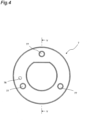
Fig. 3 is a top view of the second balance weight of the compressor of the first embodiment. -
Fig. 4 is a bottom view of the second balance weight of the compressor of the first embodiment. -
Fig. 5 is a cross-sectional view taken along line V-V inFig. 4 . -
Fig. 6 is a circuit diagram of an air conditioner as an example of a refrigeration apparatus including a refrigerant circuit using a compressor of a second embodiment of the present disclosure. - Hereinafter, embodiments will be described. Note that, in the drawings, the same reference numerals represent the same or corresponding parts. In addition, the dimensions on the drawing such as the length, the width, the thickness, and the depth are appropriately changed from the actual scale for clarity and simplification of the drawing, and do not represent the actual relative dimensions.
-
Fig. 1 is a longitudinal cross-sectional view of a compressor CMP of a first embodiment of the present disclosure. - As shown in
Fig. 1 , the compressor CMP of the first embodiment includes a hermetic container 1, acompression mechanism unit 2 disposed in the hermetic container 1, and amotor 3 disposed in the hermetic container 1 and configured to drive thecompression mechanism unit 2 via ashaft 12. The hermetic container 1 is an example of a casing. - The compressor CMP is a single-cylinder rotary compressor of a swing piston type. In the compressor CMP, the
compression mechanism unit 2 is disposed on a lower side of the hermetic container 1, and themotor 3 is disposed above thecompression mechanism unit 2. Themotor 3 includes anannular stator 4 fixed inside the hermetic container 1, and acylindrical rotor 5 disposed inside thestator 4 and fixed to theshaft 12. The rotation of therotor 5 drives thecompression mechanism unit 2 via theshaft 12. Themotor 3 is an example of an inner rotor motor. - The
compression mechanism unit 2 sucks refrigerant gas from anaccumulator 10 through asuction pipe 11. Controlling a condenser, an expansion mechanism, and an evaporator (not shown) that constitute an air conditioner as an example of a refrigeration apparatus together with the compressor CMP generates the refrigerant gas. - The compressor CMP is configured to discharge compressed high-temperature and high-pressure refrigerant gas (gas to be discharged) from the
compression mechanism unit 2 to fill the hermetic container 1 with the refrigerant gas and to cause the refrigerant gas to pass through a gap between thestator 4 and therotor 5 of themotor 3 to cool themotor 3. Furthermore, the compressor CMP is configured such that the refrigerant gas from the gap is discharged to the outside from adischarge pipe 13 provided above themotor 3. - Formed below a high-pressure area in the hermetic container 1 is an
oil sump 9 in which a lubricating oil is stored. The lubricating oil moves from theoil sump 9 to a sliding portion of thecompression mechanism unit 2 through anoil passage 80 provided in theshaft 12 to lubricate the sliding portion. - The
compression mechanism unit 2 includes afront head 30 attached to an inner surface of the hermetic container 1, acylinder 20 attached to a lower side of thefront head 30, and arear head 40 attached to a lower side of thecylinder 20. Thecylinder 20, thefront head 30, and therear head 40 forms acylinder chamber 21. - The compressor CMP includes a
piston 22 formed integrally with a roller and a blade. In thecylinder chamber 21 sandwiched between thefront head 30 and therear head 40, thepiston 22 is driven via theshaft 12 to swing. The inner space of thecylinder chamber 21 is partitioned into a high pressure side and a low pressure side by the blade (not shown) of thepiston 22. - The
front head 30 has a disk-shapedmain body 31 and aboss 32 provided at a center of themain body 31 and extending upward. Theshaft 12 passes through themain body 31 and theboss 32. - A cup-
shaped muffler cover 50 is attached to an upper side of themain body 31 so as to cover a discharge valve (not shown). Thismuffler cover 50 is fixed to themain body 31 with a bolt or the like. Theboss 32 passes through themuffler cover 50. The muffler cover 50 and thefront head 30 form a muffler chamber. - The
rear head 40 has a disk-shapedmain body 41 and aboss 42 provided at a center of themain body 41 and extending downward. Theshaft 12 passes through themain body 41 and theboss 42. - The
shaft 12 has one end rotatably supported by a bearing of thefront head 30 and a bearing of therear head 40. Theshaft 12 has one end (supported end side) extending into thecylinder chamber 21. - On the supported end side of the
shaft 12, aneccentric portion 12a is provided so as to be located in thecylinder chamber 21 of thecompression mechanism unit 2. Thiseccentric portion 12a of theshaft 12 is fitted to the roller of thepiston 22. Thispiston 22 is disposed revolvable in thecylinder chamber 21, and the revolving motion of thepiston 22 causes a compression action. - In the
compression mechanism unit 2, therear head 40, thecylinder 20, and thefront head 30 are placed on top of each other in this order, and the rotation of theshaft 12 having theeccentric portion 12a causes thepiston 22 to circle along the inner peripheral surface of thecylinder chamber 21 formed in thecylinder 20. The refrigerant gas is sucked into thecylinder chamber 21 through asuction port 20a provided in thecylinder 20 by the circling motion of thepiston 22, compressed in thecylinder chamber 21, and then discharge into the hermetic container 1 through a discharge port (not shown). - A
first balance weight 6 is further provided on an upper end surface (one end surface in the axial direction) of therotor 5. On the other hand, asecond balance weight 7 is provided on a lower end surface (the other end surface in the axial direction) of therotor 5. The first andsecond balance weights rotor 5 by rivets (not shown). Thefirst balance weight 6 is in close contact with the upper end surface of therotor 5, and thesecond balance weight 7 is in close contact with the lower end surface of therotor 5. Thesecond balance weight 7 is an example of the balance weight of the present disclosure. - The first and
second balance weights shaft 12 caused by theeccentric portion 12a. The first andsecond balance weights second balance weights - The
first balance weight 6 is similar in configuration to thesecond balance weight 7 except for a communication path, and is smaller in size than thesecond balance weight 7. -
Fig. 2 is a perspective view of thesecond balance weight 7, andFig. 3 is a top view of thesecond balance weight 7. InFigs. 2 and3 , areference numeral 7a denotes a through hole with a large diameter through which theshaft 12 passes, and areference numeral 77 denotes a through hole with a small diameter through which the rivet (not shown) passes. - As shown in
Figs. 2 and3 , thesecond balance weight 7 includes anend surface 71 facing therotor 5, an annular outerperipheral surface 72, a recessedportion 73 provided on theend surface 71, awall portion 74 provided between the recessedportion 73 and the annular outerperipheral surface 72, and a plurality ofgrooves 75 provided at an upper end of thewall portion 74, the plurality ofgrooves 75 serving as communication paths that allow a space within the recessedportion 73 and a space outer in a radial direction than thewall portion 74 to communicate with each other. - The plurality of
grooves 75 are formed on thewall portion 74 of thesecond balance weight 7 radially about a center axis O1 of therotor 5. - The recessed
portion 73 of thesecond balance weight 7 has adrain hole 76 formed in a bottom 73a of the recessedportion 73. - In a compressor having a configuration where a balance weight is covered with a cover (for example, the compressor disclosed in
JP 2021-17849 A - In order to solve such a problem, the compressor CMP according to the present disclosure includes the plurality of grooves 75 (communication paths) that allow the space defined by the recessed
portion 73 of thesecond balance weight 7 and the space outside in the radial direction with respect to thewall portion 74 to communicate with each other. This allows the refrigerating machine oil collected in the space (cavity) of the recessedportion 73 of thesecond balance weight 7 to flow out of thesecond balance weight 7. It is therefore possible to suppress vibrations of the compressor CMP. - For example, in the first embodiment described above, the plurality of grooves 75 (communication paths) that allow the space of the recessed
portion 73 and the space on the outer side of thewall portion 74 in the radial direction to communicate with each other are provided on thesecond balance weight 7, but similar communication paths may be provided on thefirst balance weight 6. - It is possible to cause, by forming the plurality of grooves 75 (the plurality of paths) as communication paths on the
wall portion 74 of thesecond balance weight 7 radially around the center axis O1 of therotor 5, the refrigerating machine oil collected in the space (cavity) of the recessedportion 73 of thesecond balance weight 7 to effectively flow out by centrifugal force of the rotor. - It is possible to easily form, by providing the
grooves 75 at the upper end of thewall portion 74 of thesecond balance weight 7, communication paths that allow the space of the recessedportion 73 of thesecond balance weight 7 and the space on the outer side of thewall portion 74 in the radial direction to communicate with each other. Providing thegrooves 75 at the upper end of thewall portion 74 of thesecond balance weight 7 by molding using a mold makes the formation of the communication paths simple as compared with providing a through hole in thewall portion 74. - For example, the through hole as a communication path may be provided in the
wall portion 74 of thesecond balance weight 7. - It is possible to cause, by providing the
drain hole 76 in the bottom of the recessedportion 73 of thesecond balance weight 7, the refrigerating machine oil collected by its own weight at the bottom 73a of the recessedportion 73 of thesecond balance weight 7 to flow out efficiently. For example, when the refrigerating machine oil can be sufficiently drained through the communication paths, thedrain hole 76 need not be provided. -
Fig. 4 is a bottom view of thesecond balance weight 7, andFig. 5 is a cross-sectional view taken along line V-V inFig. 4 . - For example, in the first embodiment, the plurality of
grooves 75 serving as communication paths are provided on thewall portion 74 of thesecond balance weight 7, but the communication paths may be through holes provided in the wall portion of the balance weight. -
Fig. 6 is a circuit diagram of an air conditioner as an example of a refrigeration apparatus including a refrigerant circuit RC using a compressor CMP of a second embodiment of the present disclosure. - As shown in
Fig. 6 , the air conditioner of the second embodiment includes an indoor unit U1 installed in an indoor space to be air-conditioned and an outdoor unit U2 installed outdoors. - The indoor unit U1 of the air conditioner includes an
indoor heat exchanger 1004 having one end connected to a refrigerant pipe L4 (connection pipe) and the other end connected to a refrigerant pipe L5 (connection pipe), and anindoor fan 1006 that supplies air to theindoor heat exchanger 1004. Theindoor fan 1006 blows out, toward the indoor space, air having temperature or the like adjusted by theindoor heat exchanger 1004. - The outdoor unit U2 of the air conditioner includes the compressor CMP, a four-
way switching valve 1001, anoutdoor heat exchanger 1002, anexpansion valve 1003 as an example of an expansion mechanism, theaccumulator 10, and anoutdoor fan 1005 that sends air to theoutdoor heat exchanger 1002. - The compressor CMP has a discharge side connected to a first port a of the four-
way switching valve 1001 via a refrigerant pipe L1. The four-way switching valve 1001 has a second port b connected to one end of theoutdoor heat exchanger 1002 via a refrigerant pipe L2. Theoutdoor heat exchanger 1002 has the other end connected to one end of theexpansion valve 1003 via a refrigerant pipe L3, and theexpansion valve 1003 has the other end connected to one end of the refrigerant pipe L4 (connection pipe). The refrigerant pipe L5 (connection pipe) has one end connected to a third port c of the four-way switching valve 1001. The four-way switching valve 1001 has a fourth port d connected to a suction side of the compressor CMP via a refrigerant pipe L6, theaccumulator 10, and thesuction pipe 11. - The refrigerant flowing through the
outdoor heat exchanger 1002 exchanges heat with air sucked by theoutdoor fan 1005. - The
expansion valve 1003 is, for example, an electric valve whose opening degree is adjustable, and the opening degree changes according to a signal from a control device (not shown). - Furthermore, the refrigerant circuit RC of the air conditioner includes the
indoor heat exchanger 1004, the compressor CMP, the four-way switching valve 1001, theoutdoor heat exchanger 1002, theexpansion valve 1003, theaccumulator 10, the refrigerant pipes L1 to L6, and thesuction pipe 11. This configures an annular refrigerant circuit RC. - As shown in
Fig. 6 , the four-way switching valve 1001 is switched to a switching position indicated by the solid line for cooling operation and is switched to a switching position indicated by the dotted line for heating operation to drive the compressor CMP, thereby causing the refrigerant to circulate through the refrigerant circuit RC. - According to the air conditioner having the above configuration, it is possible to achieve, by providing the refrigerant circuit RC using the compressor CMP, an air conditioner with suppressed compressor vibrations.
- In the second embodiment, the air conditioner has been described as the refrigeration apparatus, but the refrigeration apparatus including the refrigerant circuit RC using the compressor CMP is not limited to the air conditioner, and may be a refrigeration apparatus having another configuration.
- In the first and second embodiments, the single-cylinder rotary compressor has been described, but the present disclosure may be applied to a compressor having another configuration such as a two-cylinder rotary compressor or a swing compressor.
- The foregoing description concerns specific embodiments of the present disclosure; however, the present disclosure is not limited to the first and second embodiments, and various modifications and variations may be made within the scope of the present disclosure.
-
- 1
- Hermetic container (casing)
- 2
- Compression mechanism unit
- 3
- Motor
- 4
- Stator
- 5
- Rotor
- 6
- First balance weight
- 7
- Second balance weight
- 7a
- Through hole with a small diameter
- 9
- Oil sump
- 10
- Accumulator
- 11
- Suction pipe
- 12
- Shaft
- 12a
- Eccentric portion
- 13
- Discharge pipe
- 20
- Cylinder
- 20a
- Suction port
- 21
- Cylinder chamber
- 22
- Piston
- 30
- Front head
- 31
- Main body
- 32
- Boss
- 40
- Rear head
- 41
- Main body
- 42
- Boss
- 50
- Muffler cover
- 71
- End surface
- 72
- Outer peripheral surface
- 73
- Recessed portion
- 73a
- Bottom
- 74
- Wall portion
- 75
- Groove (communication path)
- 76
- Drain hole
- 77
- Through hole with a large diameter
- 80
- Oil passage
- CMP
- Compressor
- RC
- Refrigerant circuit
Claims (6)
- A compressor (CMP) comprising:a casing (1);a compression mechanism unit (2) provided in the casing (1); anda motor (3) that is provided in the casing (1) and drives the compression mechanism unit (2),whereinthe motor (3) includes a rotor (5) and a balance weight (7), the rotor (5) having a cylindrical shape, the balance weight (7) being provided on an end surface of the rotor (5) in an axial direction and having an annular outer peripheral surface (72), andthe balance weight (7) includes an end surface (71), a recessed portion (73), a wall portion (74), and a communication path (75), the end surface (71) facing the rotor (5), the recessed portion (73) being provided on the end surface (71), the wall portion (74) being provided between the recessed portion (73) and the outer peripheral surface (72), the communication path (75) being provided on the wall portion (74) and allowing a space of the recessed portion (73) and a space on an outer side of the wall portion (74) in a radial direction to communicate with each other.
- The compressor (CMP) according to claim 1, wherein the communication path (75) includes a plurality of paths formed on the wall portion (74) of the balance weight (7) radially around a center axis (O1) of the rotor (5).
- The compressor (CMP) according to claim 1 or 2, wherein the communication path (75) includes a groove provided at an upper end of the wall portion (74) of the balance weight (7).
- The compressor (CMP) according to any one of claims 1 to 3, wherein the communication path includes a through hole provided in the wall portion (74) of the balance weight (7).
- The compressor (CMP) according to any one of claims 1 to 4, wherein a drain hole (76) is provided in a bottom (73a) of the recessed portion (73) of the balance weight (7).
- A refrigeration apparatus comprising a refrigerant circuit (RC) using a compressor (CMP) according to any one of claims 1 to 5.
Applications Claiming Priority (2)
| Application Number | Priority Date | Filing Date | Title |
|---|---|---|---|
| JP2022093946A JP7469684B2 (en) | 2022-06-09 | 2022-06-09 | Compressors and refrigeration equipment |
| PCT/JP2023/017765 WO2023238596A1 (en) | 2022-06-09 | 2023-05-11 | Compressor and refrigeration device |
Publications (3)
| Publication Number | Publication Date |
|---|---|
| EP4509717A1 true EP4509717A1 (en) | 2025-02-19 |
| EP4509717A4 EP4509717A4 (en) | 2025-07-09 |
| EP4509717B1 EP4509717B1 (en) | 2026-06-17 |
Family
ID=89118209
Family Applications (1)
| Application Number | Title | Priority Date | Filing Date |
|---|---|---|---|
| EP23819580.4A Active EP4509717B1 (en) | 2022-06-09 | 2023-05-11 | Compressor and refrigeration device |
Country Status (5)
| Country | Link |
|---|---|
| US (1) | US20250096640A1 (en) |
| EP (1) | EP4509717B1 (en) |
| JP (1) | JP7469684B2 (en) |
| CN (1) | CN119053788A (en) |
| WO (1) | WO2023238596A1 (en) |
Family Cites Families (5)
| Publication number | Priority date | Publication date | Assignee | Title |
|---|---|---|---|---|
| JP2002317775A (en) * | 2001-04-20 | 2002-10-31 | Fujitsu General Ltd | Scroll compressor |
| JP6048044B2 (en) * | 2012-09-28 | 2016-12-21 | ダイキン工業株式会社 | Rotary compressor |
| JP2021017849A (en) | 2019-07-19 | 2021-02-15 | ダイキン工業株式会社 | Compressor |
| JP7454477B2 (en) * | 2019-11-13 | 2024-03-22 | 日立ジョンソンコントロールズ空調株式会社 | Compressor and air conditioner |
| CN112324639B (en) * | 2020-11-03 | 2023-01-20 | 珠海格力节能环保制冷技术研究中心有限公司 | Counterweight structure and compressor with same |
-
2022
- 2022-06-09 JP JP2022093946A patent/JP7469684B2/en active Active
-
2023
- 2023-05-11 WO PCT/JP2023/017765 patent/WO2023238596A1/en not_active Ceased
- 2023-05-11 EP EP23819580.4A patent/EP4509717B1/en active Active
- 2023-05-11 CN CN202380032845.6A patent/CN119053788A/en active Pending
-
2024
- 2024-11-27 US US18/963,420 patent/US20250096640A1/en active Pending
Also Published As
| Publication number | Publication date |
|---|---|
| EP4509717A4 (en) | 2025-07-09 |
| JP7469684B2 (en) | 2024-04-17 |
| US20250096640A1 (en) | 2025-03-20 |
| JP2023180557A (en) | 2023-12-21 |
| CN119053788A (en) | 2024-11-29 |
| EP4509717B1 (en) | 2026-06-17 |
| WO2023238596A1 (en) | 2023-12-14 |
Similar Documents
| Publication | Publication Date | Title |
|---|---|---|
| US10890186B2 (en) | Compressor | |
| US8689581B2 (en) | Rotary-type fluid machine and refrigeration cycle apparatus | |
| JPH02196188A (en) | rotary compressor | |
| EP1947335A2 (en) | Reciprocating compressor, in particular of the semi-hermetic type | |
| CN110662902A (en) | Sealed refrigeration compressor and refrigerating device | |
| US20250096640A1 (en) | Compressor and refrigeration device | |
| JP7267087B2 (en) | Air conditioning compressor | |
| JP6745913B2 (en) | Compressor | |
| JP6974769B2 (en) | Compressor | |
| JP6501883B2 (en) | Scroll compressor | |
| CN112412789B (en) | Compressor and refrigeration cycle device | |
| WO2006112168A1 (en) | Fluid machine | |
| WO2021214913A1 (en) | Compressor | |
| JP4743377B2 (en) | Scroll compressor | |
| WO2005028869A1 (en) | Rotational motor and electric compressor | |
| JP2024002273A (en) | Rotary compressor and refrigeration equipment | |
| JP3721587B2 (en) | Hermetic electric compressor | |
| JP6192801B2 (en) | Compressor | |
| US20260002533A1 (en) | Rotary compressor and refrigeration apparatus | |
| JP7598080B1 (en) | Compressors and refrigeration equipment | |
| US20240230175A1 (en) | Compressor unit and refrigeration apparatus | |
| CN221568843U (en) | Compressor and air conditioner | |
| CN221568842U (en) | Compressor and air conditioner | |
| CN221568844U (en) | Compressor and air conditioner | |
| JP7378275B2 (en) | Compressor, outdoor unit and air conditioner |
Legal Events
| Date | Code | Title | Description |
|---|---|---|---|
| STAA | Information on the status of an ep patent application or granted ep patent |
Free format text: STATUS: THE INTERNATIONAL PUBLICATION HAS BEEN MADE |
|
| PUAI | Public reference made under article 153(3) epc to a published international application that has entered the european phase |
Free format text: ORIGINAL CODE: 0009012 |
|
| STAA | Information on the status of an ep patent application or granted ep patent |
Free format text: STATUS: REQUEST FOR EXAMINATION WAS MADE |
|
| 17P | Request for examination filed |
Effective date: 20241112 |
|
| AK | Designated contracting states |
Kind code of ref document: A1 Designated state(s): AL AT BE BG CH CY CZ DE DK EE ES FI FR GB GR HR HU IE IS IT LI LT LU LV MC ME MK MT NL NO PL PT RO RS SE SI SK SM TR |
|
| A4 | Supplementary search report drawn up and despatched |
Effective date: 20250611 |
|
| RIC1 | Information provided on ipc code assigned before grant |
Ipc: F04C 29/06 20060101ALI20250604BHEP Ipc: F04C 18/356 20060101ALI20250604BHEP Ipc: F04C 18/02 20060101ALI20250604BHEP Ipc: F04C 29/00 20060101ALI20250604BHEP Ipc: F04C 23/00 20060101ALI20250604BHEP Ipc: F04B 39/02 20060101ALI20250604BHEP Ipc: F04B 39/00 20060101ALI20250604BHEP Ipc: F04C 29/02 20060101AFI20250604BHEP |
|
| DAV | Request for validation of the european patent (deleted) | ||
| DAX | Request for extension of the european patent (deleted) | ||
| P01 | Opt-out of the competence of the unified patent court (upc) registered |
Free format text: CASE NUMBER: UPC_APP_3797_4509717/2025 Effective date: 20250820 |
|
| GRAP | Despatch of communication of intention to grant a patent |
Free format text: ORIGINAL CODE: EPIDOSNIGR1 |
|
| STAA | Information on the status of an ep patent application or granted ep patent |
Free format text: STATUS: GRANT OF PATENT IS INTENDED |
|
| RIC1 | Information provided on ipc code assigned before grant |
Ipc: F04C 29/02 20060101AFI20260211BHEP Ipc: F04B 39/00 20060101ALI20260211BHEP Ipc: F04B 39/02 20060101ALI20260211BHEP Ipc: F04C 23/00 20060101ALI20260211BHEP Ipc: F04C 29/00 20060101ALI20260211BHEP Ipc: F04C 18/02 20060101ALI20260211BHEP Ipc: F04C 18/356 20060101ALI20260211BHEP Ipc: F04C 29/06 20060101ALI20260211BHEP |
|
| INTG | Intention to grant announced |
Effective date: 20260312 |
|
| GRAS | Grant fee paid |
Free format text: ORIGINAL CODE: EPIDOSNIGR3 |
|
| GRAA | (expected) grant |
Free format text: ORIGINAL CODE: 0009210 |
|
| STAA | Information on the status of an ep patent application or granted ep patent |
Free format text: STATUS: THE PATENT HAS BEEN GRANTED |
|
| AK | Designated contracting states |
Kind code of ref document: B1 Designated state(s): AL AT BE BG CH CY CZ DE DK EE ES FI FR GB GR HR HU IE IS IT LI LT LU LV MC ME MK MT NL NO PL PT RO RS SE SI SK SM TR |
|
| REG | Reference to a national code |
Ref country code: CH Ref legal event code: F10 Free format text: ST27 STATUS EVENT CODE: U-0-0-F10-F00 (AS PROVIDED BY THE NATIONAL OFFICE) Effective date: 20260617 Ref country code: GB Ref legal event code: FG4D |
|
| REG | Reference to a national code |
Ref country code: DE Ref legal event code: R096 Ref document number: 602023018703 Country of ref document: DE |
|
| REG | Reference to a national code |
Ref country code: IE Ref legal event code: FG4D |