EP4508331B1 - Verfahren zur steuerung einer umwälzpumpe - Google Patents
Verfahren zur steuerung einer umwälzpumpe Download PDFInfo
- Publication number
- EP4508331B1 EP4508331B1 EP24720117.1A EP24720117A EP4508331B1 EP 4508331 B1 EP4508331 B1 EP 4508331B1 EP 24720117 A EP24720117 A EP 24720117A EP 4508331 B1 EP4508331 B1 EP 4508331B1
- Authority
- EP
- European Patent Office
- Prior art keywords
- pump
- openness
- value
- control
- determined
- Prior art date
- Legal status (The legal status is an assumption and is not a legal conclusion. Google has not performed a legal analysis and makes no representation as to the accuracy of the status listed.)
- Active
Links
Images


Classifications
-
- F—MECHANICAL ENGINEERING; LIGHTING; HEATING; WEAPONS; BLASTING
- F04—POSITIVE - DISPLACEMENT MACHINES FOR LIQUIDS; PUMPS FOR LIQUIDS OR ELASTIC FLUIDS
- F04B—POSITIVE-DISPLACEMENT MACHINES FOR LIQUIDS; PUMPS
- F04B49/00—Control, e.g. of pump delivery, or pump pressure of, or safety measures for, machines, pumps, or pumping installations, not otherwise provided for, or of interest apart from, groups F04B1/00 - F04B47/00
- F04B49/22—Control, e.g. of pump delivery, or pump pressure of, or safety measures for, machines, pumps, or pumping installations, not otherwise provided for, or of interest apart from, groups F04B1/00 - F04B47/00 by means of valves
- F04B49/225—Control, e.g. of pump delivery, or pump pressure of, or safety measures for, machines, pumps, or pumping installations, not otherwise provided for, or of interest apart from, groups F04B1/00 - F04B47/00 by means of valves with throttling valves or valves varying the pump inlet opening or the outlet opening
-
- F—MECHANICAL ENGINEERING; LIGHTING; HEATING; WEAPONS; BLASTING
- F04—POSITIVE - DISPLACEMENT MACHINES FOR LIQUIDS; PUMPS FOR LIQUIDS OR ELASTIC FLUIDS
- F04B—POSITIVE-DISPLACEMENT MACHINES FOR LIQUIDS; PUMPS
- F04B49/00—Control, e.g. of pump delivery, or pump pressure of, or safety measures for, machines, pumps, or pumping installations, not otherwise provided for, or of interest apart from, groups F04B1/00 - F04B47/00
- F04B49/20—Control, e.g. of pump delivery, or pump pressure of, or safety measures for, machines, pumps, or pumping installations, not otherwise provided for, or of interest apart from, groups F04B1/00 - F04B47/00 by changing the driving speed
-
- F—MECHANICAL ENGINEERING; LIGHTING; HEATING; WEAPONS; BLASTING
- F04—POSITIVE - DISPLACEMENT MACHINES FOR LIQUIDS; PUMPS FOR LIQUIDS OR ELASTIC FLUIDS
- F04C—ROTARY-PISTON, OR OSCILLATING-PISTON, POSITIVE-DISPLACEMENT MACHINES FOR LIQUIDS; ROTARY-PISTON, OR OSCILLATING-PISTON, POSITIVE-DISPLACEMENT PUMPS
- F04C14/00—Control of, monitoring of, or safety arrangements for, machines, pumps or pumping installations
- F04C14/08—Control of, monitoring of, or safety arrangements for, machines, pumps or pumping installations characterised by varying the rotational speed
-
- F—MECHANICAL ENGINEERING; LIGHTING; HEATING; WEAPONS; BLASTING
- F04—POSITIVE - DISPLACEMENT MACHINES FOR LIQUIDS; PUMPS FOR LIQUIDS OR ELASTIC FLUIDS
- F04C—ROTARY-PISTON, OR OSCILLATING-PISTON, POSITIVE-DISPLACEMENT MACHINES FOR LIQUIDS; ROTARY-PISTON, OR OSCILLATING-PISTON, POSITIVE-DISPLACEMENT PUMPS
- F04C14/00—Control of, monitoring of, or safety arrangements for, machines, pumps or pumping installations
- F04C14/10—Control of, monitoring of, or safety arrangements for, machines, pumps or pumping installations characterised by changing the positions of the inlet or outlet openings with respect to the working chamber
-
- F—MECHANICAL ENGINEERING; LIGHTING; HEATING; WEAPONS; BLASTING
- F04—POSITIVE - DISPLACEMENT MACHINES FOR LIQUIDS; PUMPS FOR LIQUIDS OR ELASTIC FLUIDS
- F04D—NON-POSITIVE-DISPLACEMENT PUMPS
- F04D15/00—Control, e.g. regulation, of pumps, pumping installations or systems
- F04D15/0066—Control, e.g. regulation, of pumps, pumping installations or systems by changing the speed, e.g. of the driving engine
Definitions
- the present disclosure is directed to a method for controlling a circulation pump being installed in a system for heating or cooling, wherein the system is equipped with one or more temperature-controlled valves.
- the system may be an ordinary household heating system with radiators that are equipped with temperature-controlled valves, e.g. thermostatic radiator valves (TRVs).
- TRVs thermostatic radiator valves
- the temperature-controlled valves of the system may be "smart valves" being remotely temperature-controlled by a smart valve application.
- the valves When the piping system comprises temperature-controlled valves, the valves gradually close when the demand for thermal energy decreases and they gradually open when the demand for thermal energy increases in order to achieve a target temperature.
- the circulation pump as a stand-alone pump assembly does not get any direct information about how much the valves are opened or closed. If the pump sticks to its set pump control curve, it may run with an unnecessary high speed when the valves close or with a too low speed when the valves open. A too high speed of the pump waists energy saving potential and leads to undesired flow noise. A too low speed of the pump has a negative impact on the user comfort, because the cooling or heating system does not achieve its target temperatures, at least not within a desired time frame.
- EP 0 726 396 B1 or EP 1 323 986 B1 describe such an automatic adaptation of the pump control curve in a closed-loop control.
- the document CN 110 337 568 discloses a pump where the change of the pump delivery flow caused by the decrease of the rotational speed is balanced by opening the thermostat valve of the heating body.
- the document SE 2 251 177 describes a pump control where the operating point is formed by the intersection of the pump characteristic curve and the system characteristic curve.
- the method comprises:
- the term "common degree of openness" of the one or more temperature-controlled valves i.e. in form of proportional control valves, is to be understood as an absolute or relative measure of how much open or closed all those temperature-controlled valves are through which the circulation pump pumps heating or cooling liquid, e.g. ranging from 0% to 100%. If only one valve exists in the system, the "common degree of openness” may simply be the opening degree of said valve. If there are two or more valves in the system, a weighted or unweighted average of the opening degrees of the valves may be considered as the "common degree of openness".
- a stand-alone pump assembly has no information about the common degree of openness, but it "feels" a pipe resistance that scales with the common degree of openness of the valves.
- the pump experiences the lowest pipe resistance.
- the pipe resistance is constant as long as the common degree of openness of the valves does not change.
- the system characteristic curve varies with the pipe resistance, i.e. it varies with the common degree of openness of the valves. If the system characteristic curve changes, the pump characteristic curve is adapted by changing the pump speed to keep the operating point on the pump control curve. If the pump control curve, e.g. a proportional pressure control curve in form of a linear line in a head-flow-diagram, is fixed, undesirable situations occur in which the pump does not run at full speed when the valves are fully open for high thermal energy demand and in which the pump runs too quickly when the valves are nearly or fully closed for low or no thermal energy demand.
- the pump control curve e.g. a proportional pressure control curve in form of a linear line in a head-flow-diagram
- the common degree of openness of the valves in a desired range between a minimum common degree of openness and a maximum common degree of openness.
- the temperature-controlled valves can react to a rise and fall of the thermal energy demand.
- the pump control curve is not fixed, but adjustable to keep the common degree of openness of the valves within the desired range as much as possible.
- the inventive idea is now to speed up the adjustment of the pump control curve by determining a system variable that is susceptible to system characteristic curve changes and by using the system variable as an input to provide a feed forward signal to automatically adjust the pump control curve in a feed forward control.
- the system variable may be the flow factor, also denoted as kv-value.
- the kv-value is, for example, defined in " Fluidic characteristic quantities of control valves and their determination", VDI, VDE, September 2007, 2173, retrieved 17 April 2020 .
- the kv-value expresses the amount of water flow in units of m 3 /h through the system at a given common degree of openness with a pressure drop of 1 bar across the valves. It should be noted that the complete definition says that the flow medium must have a specific gravity of 1000 kg/m 3 and a kinematic viscosity of 10 -6 m 2 /s, e.g. water.
- the pump is able to determine or estimate the system variable based on its current operating point and performance indicators, such as its provided head and/or flow, its current pump speed, power consumption and/or the electric current currently drawn by the pump drive motor.
- the determined or estimated system variable is then used as an input to provide a feed forward signal to automatically adjust the pump control curve in a feed forward control.
- the method may further comprise continuously or regularly monitoring a head value h indicative of the head currently provided by the circulation pump and a flow value q indicative of the flow currently provided by the circulation pump, wherein the head value h and the flow value q are used to determine the system variable, e.g. the kv-value.
- the system variable e.g. the kv-value.
- the step of automatically adjusting the pump control curve may further comprise:
- automatically adjusting the pump control curve may further comprise using a stored adaptable mapping between the system variable and the feed forward signal to be applied for the feed forward control. This is beneficial to account for deviations from the target opening degree as indicated by a PI controller.
- the mapping used for the feed forward may be adapted to keep the deviation from the target opening degree at a minimum.
- a deviation of the determined common degree of openness value from a pre-determined reference common degree of openness may be used as a further input in addition to the system variable to provide the feed forward signal, and wherein said deviation is used to update the stored adaptable mapping.
- this further input is, under normal operation, much smaller than the contribution of the system variable to the feed forward control.
- the contribution of the deviation of the opening degree from the target opening degree is rather a minor correction, e.g. in the range of +/- 5%, to the feed forward control.
- the stored adaptable mapping may comprise a list of relative values defining which pump control curve is applied within a total range of applicable pump control curves at pre-determined system variable points, wherein the relative values are interpolated between the pre-determined system variable points.
- the applicable pump control curves may range between a lowest proportional pressure curve PP1 and a highest proportional pressure curve PP3.
- the stored adaptable mapping may comprise a list of relative values in terms of percentage ranging from 0% for the lowest proportional pressure curve PP1 and 100% for the highest proportional pressure curve PP3.
- the stored adaptable mapping may be updated only for the one or two relative value(s) at those pre-determined system variable point(s) that are closest to the currently determined system variable if the updated mapping has a throughout non-negative gradient, and wherein otherwise the stored adaptable mapping is updated in addition
- the adjustable pump control curve may be a proportional pressure curve. This is particularly beneficial if the valves are installed at heating radiators.
- the system may comprise one or more thermal energy consumers and the one or more temperature-controlled valves may be automatically and/or thermostatically actuated valves installed at said thermal energy consumers.
- the thermal energy consumers are radiators of a heating system.
- the feed forward signal may be low-pass filtered with a predetermined time constant before it is used to automatically adjust the pump control curve in the feed forward control if the determined system variable is smaller than the previously determined system variable.
- This is particularly beneficial to avoid undesired rapid oscillations between the control curves.
- Such oscillations have shown to occur at households with low variations of the kv-value, where small changes of the opening degree of the valves may lead to larger changes of the pump head which the valves try to compensate.
- a first order filter for instance with a time constant of 1200 seconds, may be applied if the kv-value is dropping.
- a rising kv-value may be used unfiltered as input into the feed forward control.
- the pump control curve may be adjustable without steps within a total range of applicable pump characteristic curves.
- the method may further comprise operating the pump in a first boost mode and/or in a second boost mode, wherein
- a computer program is provided with instructions which, when the program is executed by a computer, cause the computer to carry out the previously described method.
- a circulation pump for being installed in a system for heating or cooling, wherein the circulation pump comprises control electronics being configured to carry out the previously described method or to execute the above-mentioned program.
- the circulation pump may be automatically programmed at a manufacturing site of the circulation pump to carry out the previously described method or to execute the previously described program.
- the fully assembled circulation pump may leave the manufacturing site fully programmed for shipping to customers, such that there is no need for customers to program the circulation pump.
- the method disclosed herein may be implemented in form of compiled or uncompiled software code that is stored on a computer readable medium with instructions for executing the method.
- the software is installed on control electronics within the circulation pump according to the present invention.
- the method may be executed by software in a cloud-based system and/or a building management system (BMS).
- BMS building management system
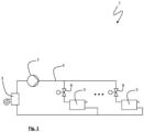
- Fig. 1 shows a system 1 for heating or cooling as it is typically installed in a household.
- the system 1 comprises a thermal energy source 3, e.g. a gas boiler, a heat exchanger, a heating coil or a heat reservoir.
- the thermal energy source 3 is connected to a piping system 4 filled with a fluid, e.g. water, for transferring thermal energy to one or more thermal energy consumers 5, e.g. radiators, underfloor heating, or heat exchangers.
- At least one circulation pump 7 is installed in the system 1 to circulate the fluid for thermal energy transfer from the thermal energy source 3 to the one or more thermal consumers 5.
- the system 1 is further equipped with one more temperature-controlled valves 9, e.g. thermostatic radiator valves (TRVs), smart valves or other kinds of temperature-controlled valves.
- Each of the temperature-controlled valves 9 may be installed in the vicinity of one of the thermal consumers 5 to control the fluid flow through that respective thermal energy consumer 5.
- the thermal energy consumers 5 are installed in parallel in the system 1, such that each of the thermal energy consumers 5 has a fluid inlet connected to a feed line of the system 1 and a fluid outlet to a return line of the system 1.
- the associated temperature-controlled valve 9 is preferably installed at a fluid inlet of the thermal energy consumer 5.
- the temperature-controlled valves 9 are each controlled by a closed-loop control using a thermostat, wherein a temperature sensor is used to determine the current temperature and a target temperature can be set for the thermostat.
- a temperature sensor is used to determine the current temperature and a target temperature can be set for the thermostat.
- the valves 9 open when the measured temperature is below a target temperature in order to increase the flow of the heating fluid through the respective thermal energy consumer 5.
- the valve 9 closes when the measured temperature is above a target temperature in order to reduce the flow of the heating fluid through the thermal energy consumer 5.
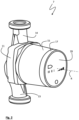
- FIG 2 shows a circulation pump 7 as it is installed in a heating or cooling system 1 as shown in figure 1 .
- the hardware of the circulation pump 7 as shown in figure 2 may not differ from a circulation pump as known in the prior art. However, it differs in the way it is programmed and thus controlled to operate.
- the circulation pump 7 comprises a pump housing 11 with a suction inlet 13 and pressure outlet 14.
- the section inlet 13 and the pressure outlet 14 comprise coaxially aligned flanges directed into opposite directions in order to be installed in a piping system 4 of a cooling or heating system 1 as shown in figure 1 .
- the pump housing 11 accommodates an impeller (not visible) that is rotatable around a rotor axis R in order to drive a fluid flow (e.g. water flow) from the suction inlet 13 to the pressure outlet 14.
- the circulation pump 7 is a wet-running circulation pump with an integrated permanent magnet synchronous motor (PMSM) within a motor housing 15.
- PMSM permanent magnet synchronous motor
- the circulation pump 7 comprises control electronics (not visible) within the motor housing 15 in order to control the speed of the circulation pump 7.
- a lid 17 of the motor housing 15 comprises a front face 19 with human-machine-interface elements, such as a display, LED indicators, one or more buttons or switchers.
- a user may manually set the circulation pump 7 to follow a fixed control curve or to run in an "auto adapt" control mode to automatically adapt the applied control curve.
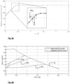
- the circulation pump 7 may be set to one of three fixed proportional pressure curves PP1, PP2 and PP3.
- figure 8b shows an example of three fixed control curves as linear lines in a head(h)-flow(q)-diagram.
- the circulation pump 7 may further comprise a wireless interface or a connector via which the control electronics within the circulation pump 7 can be programmed, reprogrammed or updated.
- the circulation pump 7 may thus be programmed at the time of manufacturing and assembly and/or when it is already installed in a cooling or heating system 1.
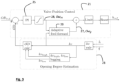
- Figure 3 shows how the circulation pump 7 of figure 2 is programmed to be controlled.
- a system variable e.g. a pipe resistance or a kv-value
- the circulation pump 7 is more proactively used to indirectly control the valve position. It should be noted that there is no direct control communication between the circulation pump 7 and the valves 9. The circulation pump 7, however, knows that the valves 9 open when they do not get sufficient thermal energy flow and that they close when they get too much thermal energy flow.
- the control schematics shown in figure 3 comprise a valve position control 21 and an opening degree estimation 23. It is the goal of the valve position control 21 to automatically adjust the control curve when the pipe resistance changes in order to keep the common degree of openness OD of the valves 9 in a desired range between a minimum common degree of openness OD min and a maximum common degree of openness OD max .
- a central range of the common degree of openness is desirable, because it leaves upward and downward control room to adjust the valve position to the current thermal energy demand.
- the valve position control 21 takes two variables as an input, i.e. a current system variable in form of a kv-value and an estimated value OD ⁇ of the current common degree of openness OD.
- the opening degree estimation 23 provides both the kv-value and the estimated common degree of openness value OD ⁇ as an output to provide these values as input into the valve position control 21.
- the opening degree estimation 23 takes as input a head value ⁇ and a flow value q ⁇ .
- the circulation pump 7 continuously or regularly monitors the head value ⁇ which is indicative of the head h currently provided by the circulation pump 7. In the same way, the circulation pump 7 continuously or regularly monitors the flow value q ⁇ which is indicative of the flow q currently provided by the circulation pump 7.
- the opening degree estimation 23 is explained in more detail with reference to figures 4 and 5 .
- the details of the valve position control 21 are explained in more detail with reference to figure 6 .
- the output of the valve position 21 is a reference value h ref indicating which proportional pressure curve is to be applied by the circulation pump 7.
- the reference value h ref is the sum of the outputs from a PI controller 25 and an adaptive feed forward signal 27.
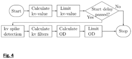
- Figure 4 shows the opening degree estimation 23 in more detail. It starts with calculating a kv-value based on the monitored head value ⁇ and monitored flow value q ⁇ .
- the kv-value is further limited to be above a predetermined minimum value, e.g. 3.5 m 3 /h. If the head value ⁇ is below a lower limit, e.g.
- Figure 5 describes how a filter is applied to the calculated kv-value in order to determine the current maximum kv-value kv high and the current minimum kv-value kv low .
- a timer is implemented to ensure that the system 1 has stabilised since the control authorism has been started.
- the estimated opening degree value OD ⁇ is only estimated if a predetermined minimum time duration, e.g. 10 minutes, has passed since the control algorithm was started.
- the start delay is checked whether the kv-value shows a spike, for example after a start-up following a night set back.
- the opening degree estimation 23 is suppressed as long as the kv-value shows such a high gradient that indicates a kv-spike. If there is no kv-spike, the calculated kv-value is filtered to determine the minimum kv-value kv low and the maximum kv-value kv high which represent the lowest and highest kv-value within a certain time frame. They are calculated using a peak detection filter with a forgetting factor.
- k vBandMin is used to protect the algorithm against divisions by zero and may be set to 0.03 for example.
- k v,dynband,min may be used to stop a re-estimation when the kv-value variations are too small, i.e. k v,dynband,min may be set to 0.05.
- the estimated opening degree value OD ⁇ is set to the reference value OD ref in case of very small variations of the kv-value. This is done to ensure that the values kv low and kv high have initialised and that there is sufficient signal-to-noise ratio in the kv-signal to perform a meaningful control.
- the PI controller 25 takes the difference between the reference common degree of openness OD ref and the estimated common degree of openness value OD ⁇ as an input error to be minimised.
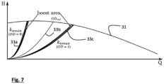
- the PI controller 25 may comprise controller parameters, such as gain, time constants and controller limitation parameter that may be predetermined for normal operation. However, the controller parameters may be set to specific values when the system 1 is in a boost area as shown in figure 7 . In particular, the controller gain and controller limitation parameter may be multiplied by a certain factor when a boost control is activated in the PI controller 25 when the system 1 is in the boost area.
- the boost of the PI controller 25 by applying a gain factor is a first boost mode according to an embodiment of the present disclosure.
- the circulation pump may in situations of particularly high thermal energy demand be operated in a second boost mode, in which the circulation pump 7 is set to maximum speed if the kv-value is within a boost area adjacent to the kv max -value and a maximum pump control curve is applied and a predetermined period of maximum boosting time has not lapsed.
- Figure 8a shows an initial mapping of 26 kv-values between zero and 2.5 m 3 /h to the relative proportional pressure curve to be applied in terms of percent.
- a relative proportional pressure curve value of 100% may represent the highest proportional pressure curve PP3.
- a relative proportional pressure curve value of 0% may represent the lowest proportional pressure curve PP1.
- the feed forward signal Out ff as the output 27 of the feed forward control 29 is an interpolation between the mapping points in figure 8a .
- the mapping of figure 8a is then stored in the control electronics of the circulation pump 7.
- a non-zero output 28 Out PI of the PI controller 25 shows as a deviation of the current kv-value from the interpolated mapping and triggers a correction of the closest two mapping points in proportion to the output 28 Out PI of the PI controller 25 such that the interpolation between those two corrected mapping points lies on the current kv-value. If the current kv-value is outside of the mapped range of kv-values, only the lowest or highest mapping point is adapted accordingly. The adapted mapping points are limited to relative proportional pressure curve values between 0% and 100%.
- mapping points at all kv-values above the adapted higher closest mapping point are shifted upward by the minimum amount that is needed to avoid the updated mapping from having a negative gradient.
- all mapping points with kv-values below said downward adapted closest lower mapping point are shifted downward by an amount that is needed to avoid the updated mapping from having a negative gradient.
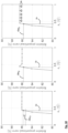
- Figure 10 shows an example how the mapping may look like before an update (on the left), after an update (in the middle) and after the mapping is adapted to avoid a negative gradient (on the right).
- Figure 10 shows on the left the mapping as it is stored before it is updated.
- a positive output 28 Out PI of the PI controller suggests that the mapping around the current kv-value should be increased. Therefore, the neighbouring mapping points are shifted upward accordingly.
- the shifting is weighted according to the distance of the current kv-value to the mapping point. In the shown case, the closest higher neighbouring mapping point is shifted more upward than the closest lower neighbouring mapping point.
- mapping points with kv-values above the closest higher neighbouring mapping point are shifted upward by the least amount A that is necessary to avoid a negative gradient.
Landscapes
- Engineering & Computer Science (AREA)
- Mechanical Engineering (AREA)
- General Engineering & Computer Science (AREA)
- Control Of Positive-Displacement Pumps (AREA)
- Feedback Control In General (AREA)
Claims (15)
- Verfahren zum Steuern einer Umwälzpumpe (7), die in einem System (1) zum Heizen oder Kühlen installiert ist, wobei das System (1) mit einem oder mehreren temperaturgesteuerten Ventilen (9) ausgestattet ist, wobei das Verfahrenein Betreiben der Pumpe bei einem Betriebspunkt, wobei der aktuelle Betriebspunkt als der Schnittpunkt einer anpassbaren Pumpenkennlinie und einer variablen Systemkennlinie (33a bis c) definiert ist, wobei sich die Systemkennlinie (33a bis c) mit einem gemeinsamen Offenheitsgrad (OD) des einen oder der mehreren temperaturgesteuerten Ventile (9) verändert, wobei die Pumpenkennlinie durch Festlegen der Geschwindigkeit der Pumpe (7) angepasst wird, wobei die Geschwindigkeit der Pumpe (7) auf eine solche Weise gesteuert wird, dass der Betriebspunkt einer einstellbaren Regelkurve folgt; und- ein automatisches Einstellen der Regelkurve, wenn sich die Systemkennlinie (33a bis c) ändert, um den gemeinsamen Offenheitsgrad (OD) des einen oder der mehreren temperaturgesteuerten Ventile (9) in einem gewünschten Bereich zwischen einem kleinsten gemeinsamen Offenheitsgrad (ODmin) und einem größten gemeinsamen Offenheitsgrad (ODmax) zu behalten,umfasst, dadurch gekennzeichnet, dass
das automatische Einstellen der Regelkurve ein Bestimmen einer Systemvariablen (kv), die für Änderungen der Systemkennlinie anfällig ist, und ein Verwenden der Systemvariablen (kv) als Eingang, um ein Vorwärtsregelungssignal (27) zum automatischen Einstellen der Regelkurve bei einer Vorwärtsregelung (29) bereitzustellen, umfasst. - Verfahren nach Anspruch 1, ferner umfassend ein fortlaufendes oder regelmäßiges Überwachen eines Förderhöhenwerts (ĥ), der die Förderhöhe (h), die aktuell durch die Umwälzpumpe (7) bereitgestellt wird, angibt, und eines Durchflusswerts (q̂), der den Durchfluss (q), der aktuell durch die Umwälzpumpe (7) bereitgestellt wird, angibt, wobei der Förderhöhenwert (ĥ) und der Durchflusswert (q̂) zur Bestimmung der Systemvariablen (kv) verwendet werden.
- Verfahren nach Anspruch 1 oder 2, wobei das automatische Einstellen der Regelkurve ferner- ein Protokollieren eines Höchstwerts (kvhigh ) und eines Mindestwerts (kvlow ) der Systemvariablen (kv), der über einen vergangenen Zeitraum bestimmt wurde; und- ein Bestimmen eines Werts des gemeinsamen Offenheitsgrads (umfasst.

- Verfahren nach einem der vorhergehenden Ansprüche, wobei das automatische Einstellen der Regelkurve ferner ein Verwenden einer gespeicherten anpassbaren Zuordnung zwischen der Systemvariablen (kv) und dem Vorwärtsregelungssignal (27), das auf die Vorwärtsregelung (29) angewendet werden soll, umfasst.
- Verfahren nach Anspruch 4, wobei eine Abweichung des bestimmten Werts des gemeinsamen Offenheitsgrad (

- Verfahren nach Anspruch 4 oder 5, wobei die gespeicherte anpassbare Zuordnung eine Liste von relativen Werten aufweist, die definiert, welche Regelkurve innerhalb eines gesamten Bereichs von anwendbaren Regelkurven an vorherbestimmten Systemvariablenpunkten angewendet wird, wobei die relativen Werte zwischen den vorherbestimmten Systemvariablenpunkten interpoliert werden.
- Verfahren nach Anspruch 6, wobei die gespeicherte anpassbare Zuordnung nur hinsichtlich des einen oder der beiden relativen Wert(e) an den vorherbestimmten Systemvariablenpunkt(en), die der aktuell bestimmten Variablen (kv) des Systems (1) am nächsten liegen, aktualisiert wird, wenn die aktualisierte Zuordnung einen durchgehend nicht-negativen Gradienten aufweist, und wobei die gespeicherte anpassbare Zuordnung andernfalls zusätzlich- hinsichtlich der relativen Werte an allen höheren vorherbestimmten Systemvariablenpunkten, indem diese relativen Werte um ein Ausmaß nach oben verschoben werden, das nötig ist, um zu vermeiden, dass die aktualisierte Zuordnung einen negativen Gradienten aufweist, und/oder- hinsichtlich der relativen Werte an allen niedrigeren vorherbestimmten Systemvariablen, indem diese relativen Werte um ein Ausmaß nach unten verschoben werden, das nötig ist, um zu vermeiden, dass die aktualisierte Zuordnung einen negativen Gradienten aufweist,aktualisiert wird.
- Verfahren nach einem der vorhergehenden Ansprüche, wobei die einstellbare Regelkurve eine Proportionaldruckkurve (PP1, PP2, PP3) ist.
- Verfahren nach einem der vorhergehenden Ansprüche, wobei das System (1) einen oder mehrere Wärmeenergieverbraucher (5) aufweist und das eine oder die mehreren temperaturgesteuerten Ventile (9) automatisch und/oder thermostatisch betätigte Ventile sind, die an den Wärmeenergieverbrauchern (5) installiert sind.
- Verfahren nach einem der vorhergehenden Ansprüche, wobei das Vorwärtsregelungssignal (27) mit einer vorherbestimmten Zeitkonstanten tiefpassgefiltert wird, bevor es verwendet wird, um die Regelkurve bei der Vorwärtsregelung (29) automatisch einzustellen, wenn die bestimmte Systemvariable (kv) kleiner als die zuvor bestimmte Systemvariable (kv) ist.
- Verfahren nach einem der vorhergehenden Ansprüche, wobei die Regelkurve innerhalb eines gesamten Bereichs der anwendbaren Pumpenkennlinien stufenlos einstellbar ist.
- Verfahren nach einem der vorhergehenden Ansprüche, ferner umfassend ein Betreiben der Pumpe in einem ersten Boost-Modus und/oder in einem zweiten Boost-Modus, wobei
in dem ersten Boost-Modus ein Verstärkungsfaktor angewendet wird, um die Regelkurve stärker einzustellen, solange ein vorherbestimmter Wert des gemeinsamen Offenheitsgrads
wobei die Pumpe in dem zweiten Boost-Modus mit einer Höchstgeschwindigkeit betreiben wird, wenn- die Systemvariable (kv) innerhalb eines vorherbestimmten Geschwindigkeits-Boost-Bereichs neben einem protokollierten Maximum (kvhigh ) der Systemvariablen (kv) liegt, und- aktuell eine maximale Regelkurve angewendet wird, und- ein vorherbestimmter Zeitraum der maximalen Boost-Zeit nicht abgelaufen ist. - Computerprogramm, das Befehle enthält, die bei Ausführung des Programms durch einen Computer den Computer dazu bringen, das Verfahren nach einem der vorhergehenden Ansprüche durchzuführen.
- Umwälzpumpe (7) zur Installation in einem System (1) zum Heizen oder Kühlen, wobei die Umwälzpumpe (7) eine Steuerelektronik aufweist, die so eingerichtet ist, dass sie das Verfahren nach einem der Ansprüche 1 bis 12 durchführt oder das Programm nach Anspruch 13 ausführt.
- Umwälzpumpe (7) nach Anspruch 14, wobei die Umwälzpumpe (7) an einem Produktionsstandort der Umwälzpumpe (7) automatisch programmiert wird, das Verfahren nach einem der Ansprüche 1 bis 12 durchzuführen oder das Programm nach Anspruch 13 auszuführen.
Applications Claiming Priority (2)
| Application Number | Priority Date | Filing Date | Title |
|---|---|---|---|
| DKPA202370348 | 2023-06-30 | ||
| PCT/EP2024/060246 WO2025002619A1 (en) | 2023-06-30 | 2024-04-16 | Method for controlling a circulation pump |
Publications (3)
| Publication Number | Publication Date |
|---|---|
| EP4508331A1 EP4508331A1 (de) | 2025-02-19 |
| EP4508331C0 EP4508331C0 (de) | 2025-06-25 |
| EP4508331B1 true EP4508331B1 (de) | 2025-06-25 |
Family
ID=90810655
Family Applications (1)
| Application Number | Title | Priority Date | Filing Date |
|---|---|---|---|
| EP24720117.1A Active EP4508331B1 (de) | 2023-06-30 | 2024-04-16 | Verfahren zur steuerung einer umwälzpumpe |
Country Status (4)
| Country | Link |
|---|---|
| EP (1) | EP4508331B1 (de) |
| CN (1) | CN119546855A (de) |
| PL (1) | PL4508331T3 (de) |
| WO (1) | WO2025002619A1 (de) |
Citations (1)
| Publication number | Priority date | Publication date | Assignee | Title |
|---|---|---|---|---|
| SE2251177A1 (en) * | 2021-10-09 | 2023-04-10 | Spm Instr Ab | A Process Optimization System |
Family Cites Families (4)
| Publication number | Priority date | Publication date | Assignee | Title |
|---|---|---|---|---|
| DE19504232A1 (de) | 1995-02-09 | 1996-08-22 | Grundfos As | Verfahren zur Leistungsbegrenzung von elektrisch angetriebenen Heizungsumwälzpumpen |
| DE10163987A1 (de) | 2001-12-24 | 2003-07-10 | Grundfos As | Verfahren zum Steuern einer drehzahlregelbaren Heizungsumwälzpumpe |
| DE102017203474A1 (de) * | 2017-03-03 | 2018-09-06 | KSB SE & Co. KGaA | Verfahren zur Regelung einer drehzahlvariablen Umwälzpumpe sowie Umwälzpumpe |
| EP4123094A1 (de) * | 2018-09-10 | 2023-01-25 | Artemis Intelligent Power Limited | Arbeitsmaschine mit hydraulik pumpe/motor steuerung |
-
2024
- 2024-04-16 WO PCT/EP2024/060246 patent/WO2025002619A1/en active Pending
- 2024-04-16 CN CN202480002630.4A patent/CN119546855A/zh active Pending
- 2024-04-16 PL PL24720117.1T patent/PL4508331T3/pl unknown
- 2024-04-16 EP EP24720117.1A patent/EP4508331B1/de active Active
Patent Citations (1)
| Publication number | Priority date | Publication date | Assignee | Title |
|---|---|---|---|---|
| SE2251177A1 (en) * | 2021-10-09 | 2023-04-10 | Spm Instr Ab | A Process Optimization System |
Also Published As
| Publication number | Publication date |
|---|---|
| PL4508331T3 (pl) | 2025-10-27 |
| EP4508331C0 (de) | 2025-06-25 |
| EP4508331A1 (de) | 2025-02-19 |
| CN119546855A (zh) | 2025-02-28 |
| WO2025002619A1 (en) | 2025-01-02 |
Similar Documents
| Publication | Publication Date | Title |
|---|---|---|
| US10635120B2 (en) | Method for operating and/or monitoring an HVAC system | |
| US9657959B2 (en) | Fan coil thermostat with fan ramping | |
| US6607140B1 (en) | Method for precise electric actuator control with reduced repositioning | |
| EP2641027B1 (de) | Vorrichtung und verfahren zur steuerung der öffnung eines ventils in einem hvac-system | |
| US8191513B2 (en) | System and method for controlling a pump in a recirculating hot water system | |
| RU2553630C2 (ru) | Способ для оптимизированной по мощности эксплуатации насоса, приводимого в действие электродвигателем, при малых объемных расходах | |
| US8538597B2 (en) | System and method for regulating temperature in a hot water heater | |
| US6758655B2 (en) | Process for determining a reference characteristic for controlling a pump | |
| US10801737B2 (en) | Method for adapting a heating curve | |
| US10788040B2 (en) | Adaptation of the delivery head of a centrifugal pump to a changing volumetric flow rate | |
| US20130048114A1 (en) | Controlled hydronic distribution system | |
| AU2014240001A1 (en) | Controller for automatic control of duty cycled HVAC&R equipment, and systems and methods using same | |
| US20150086382A1 (en) | Pumping system control | |
| EP4508331B1 (de) | Verfahren zur steuerung einer umwälzpumpe | |
| JP4249591B2 (ja) | 1次ポンプ方式熱源変流量制御システムおよび1次ポンプ最低流量確保方法 | |
| CN113383196A (zh) | 用于调节循环泵的方法 | |
| PL206213B1 (pl) | Sposób regulacji temperatury w pomieszczeniu | |
| US10844862B2 (en) | Self-sensing parallel control of pumps | |
| EP3382490B1 (de) | Verfahren zur steuerung eines hydronischen heizsystems in mehreren räumen | |
| RU2776880C2 (ru) | Способ регулирования циркуляционного насоса, циркуляционный насос, а также система отопления | |
| CN119156506A (zh) | 用于监控和/或控制供暖设备的方法 | |
| WO2025172108A1 (en) | Adapting an operation of a pump of a hot water system | |
| CA2756336A1 (en) | System and method for regulating temperature in a hot water heater |
Legal Events
| Date | Code | Title | Description |
|---|---|---|---|
| STAA | Information on the status of an ep patent application or granted ep patent |
Free format text: STATUS: UNKNOWN |
|
| STAA | Information on the status of an ep patent application or granted ep patent |
Free format text: STATUS: THE INTERNATIONAL PUBLICATION HAS BEEN MADE |
|
| PUAI | Public reference made under article 153(3) epc to a published international application that has entered the european phase |
Free format text: ORIGINAL CODE: 0009012 |
|
| STAA | Information on the status of an ep patent application or granted ep patent |
Free format text: STATUS: REQUEST FOR EXAMINATION WAS MADE |
|
| GRAP | Despatch of communication of intention to grant a patent |
Free format text: ORIGINAL CODE: EPIDOSNIGR1 |
|
| STAA | Information on the status of an ep patent application or granted ep patent |
Free format text: STATUS: GRANT OF PATENT IS INTENDED |
|
| 17P | Request for examination filed |
Effective date: 20240927 |
|
| AK | Designated contracting states |
Kind code of ref document: A1 Designated state(s): AL AT BE BG CH CY CZ DE DK EE ES FI FR GB GR HR HU IE IS IT LI LT LU LV MC ME MK MT NL NO PL PT RO RS SE SI SK SM TR |
|
| INTG | Intention to grant announced |
Effective date: 20250122 |
|
| GRAS | Grant fee paid |
Free format text: ORIGINAL CODE: EPIDOSNIGR3 |
|
| GRAA | (expected) grant |
Free format text: ORIGINAL CODE: 0009210 |
|
| STAA | Information on the status of an ep patent application or granted ep patent |
Free format text: STATUS: THE PATENT HAS BEEN GRANTED |
|
| AK | Designated contracting states |
Kind code of ref document: B1 Designated state(s): AL AT BE BG CH CY CZ DE DK EE ES FI FR GB GR HR HU IE IS IT LI LT LU LV MC ME MK MT NL NO PL PT RO RS SE SI SK SM TR |
|
| DAV | Request for validation of the european patent (deleted) | ||
| DAX | Request for extension of the european patent (deleted) | ||
| REG | Reference to a national code |
Ref country code: GB Ref legal event code: FG4D |
|
| REG | Reference to a national code |
Ref country code: CH Ref legal event code: EP |
|
| REG | Reference to a national code |
Ref country code: DE Ref legal event code: R096 Ref document number: 602024000245 Country of ref document: DE |
|
| REG | Reference to a national code |
Ref country code: CH Ref legal event code: EP |
|
| REG | Reference to a national code |
Ref country code: IE Ref legal event code: FG4D |
|
| U01 | Request for unitary effect filed |
Effective date: 20250715 |
|
| U07 | Unitary effect registered |
Designated state(s): AT BE BG DE DK EE FI FR IT LT LU LV MT NL PT RO SE SI Effective date: 20250721 |
|
| U1O | Appointed representative for the unitary patent procedure deleted after the registration of the unitary effect | ||
| PG25 | Lapsed in a contracting state [announced via postgrant information from national office to epo] |
Ref country code: NO Free format text: LAPSE BECAUSE OF FAILURE TO SUBMIT A TRANSLATION OF THE DESCRIPTION OR TO PAY THE FEE WITHIN THE PRESCRIBED TIME-LIMIT Effective date: 20250925 Ref country code: GR Free format text: LAPSE BECAUSE OF FAILURE TO SUBMIT A TRANSLATION OF THE DESCRIPTION OR TO PAY THE FEE WITHIN THE PRESCRIBED TIME-LIMIT Effective date: 20250926 |
|
| PG25 | Lapsed in a contracting state [announced via postgrant information from national office to epo] |
Ref country code: HR Free format text: LAPSE BECAUSE OF FAILURE TO SUBMIT A TRANSLATION OF THE DESCRIPTION OR TO PAY THE FEE WITHIN THE PRESCRIBED TIME-LIMIT Effective date: 20250625 |
|
| PG25 | Lapsed in a contracting state [announced via postgrant information from national office to epo] |
Ref country code: RS Free format text: LAPSE BECAUSE OF FAILURE TO SUBMIT A TRANSLATION OF THE DESCRIPTION OR TO PAY THE FEE WITHIN THE PRESCRIBED TIME-LIMIT Effective date: 20250925 |