EP4507011A1 - Method for welding cell strings and series welding machine - Google Patents
Method for welding cell strings and series welding machine Download PDFInfo
- Publication number
- EP4507011A1 EP4507011A1 EP23206387.5A EP23206387A EP4507011A1 EP 4507011 A1 EP4507011 A1 EP 4507011A1 EP 23206387 A EP23206387 A EP 23206387A EP 4507011 A1 EP4507011 A1 EP 4507011A1
- Authority
- EP
- European Patent Office
- Prior art keywords
- solar cells
- welding
- welding strips
- arrangement
- strips
- Prior art date
- Legal status (The legal status is an assumption and is not a legal conclusion. Google has not performed a legal analysis and makes no representation as to the accuracy of the status listed.)
- Pending
Links
Images




Classifications
-
- B—PERFORMING OPERATIONS; TRANSPORTING
- B23—MACHINE TOOLS; METAL-WORKING NOT OTHERWISE PROVIDED FOR
- B23K—SOLDERING OR UNSOLDERING; WELDING; CLADDING OR PLATING BY SOLDERING OR WELDING; CUTTING BY APPLYING HEAT LOCALLY, e.g. FLAME CUTTING; WORKING BY LASER BEAM
- B23K31/00—Processes relevant to this subclass, specially adapted for particular articles or purposes, but not covered by any single one of main groups B23K1/00 - B23K28/00
- B23K31/02—Processes relevant to this subclass, specially adapted for particular articles or purposes, but not covered by any single one of main groups B23K1/00 - B23K28/00 relating to soldering or welding
-
- H—ELECTRICITY
- H10—SEMICONDUCTOR DEVICES; ELECTRIC SOLID-STATE DEVICES NOT OTHERWISE PROVIDED FOR
- H10F—INORGANIC SEMICONDUCTOR DEVICES SENSITIVE TO INFRARED RADIATION, LIGHT, ELECTROMAGNETIC RADIATION OF SHORTER WAVELENGTH OR CORPUSCULAR RADIATION
- H10F19/00—Integrated devices, or assemblies of multiple devices, comprising at least one photovoltaic cell covered by group H10F10/00, e.g. photovoltaic modules
- H10F19/90—Structures for connecting between photovoltaic cells, e.g. interconnections or insulating spacers
- H10F19/902—Structures for connecting between photovoltaic cells, e.g. interconnections or insulating spacers for series or parallel connection of photovoltaic cells
- H10F19/908—Structures for connecting between photovoltaic cells, e.g. interconnections or insulating spacers for series or parallel connection of photovoltaic cells for back-contact photovoltaic cells
-
- B—PERFORMING OPERATIONS; TRANSPORTING
- B23—MACHINE TOOLS; METAL-WORKING NOT OTHERWISE PROVIDED FOR
- B23K—SOLDERING OR UNSOLDERING; WELDING; CLADDING OR PLATING BY SOLDERING OR WELDING; CUTTING BY APPLYING HEAT LOCALLY, e.g. FLAME CUTTING; WORKING BY LASER BEAM
- B23K31/00—Processes relevant to this subclass, specially adapted for particular articles or purposes, but not covered by any single one of main groups B23K1/00 - B23K28/00
- B23K31/12—Processes relevant to this subclass, specially adapted for particular articles or purposes, but not covered by any single one of main groups B23K1/00 - B23K28/00 relating to investigating the properties, e.g. the weldability, of materials
- B23K31/125—Weld quality monitoring
-
- B—PERFORMING OPERATIONS; TRANSPORTING
- B23—MACHINE TOOLS; METAL-WORKING NOT OTHERWISE PROVIDED FOR
- B23K—SOLDERING OR UNSOLDERING; WELDING; CLADDING OR PLATING BY SOLDERING OR WELDING; CUTTING BY APPLYING HEAT LOCALLY, e.g. FLAME CUTTING; WORKING BY LASER BEAM
- B23K37/00—Auxiliary devices or processes, not specially adapted for a procedure covered by only one of the other main groups of this subclass
-
- H—ELECTRICITY
- H10—SEMICONDUCTOR DEVICES; ELECTRIC SOLID-STATE DEVICES NOT OTHERWISE PROVIDED FOR
- H10F—INORGANIC SEMICONDUCTOR DEVICES SENSITIVE TO INFRARED RADIATION, LIGHT, ELECTROMAGNETIC RADIATION OF SHORTER WAVELENGTH OR CORPUSCULAR RADIATION
- H10F19/00—Integrated devices, or assemblies of multiple devices, comprising at least one photovoltaic cell covered by group H10F10/00, e.g. photovoltaic modules
- H10F19/90—Structures for connecting between photovoltaic cells, e.g. interconnections or insulating spacers
- H10F19/902—Structures for connecting between photovoltaic cells, e.g. interconnections or insulating spacers for series or parallel connection of photovoltaic cells
-
- H—ELECTRICITY
- H10—SEMICONDUCTOR DEVICES; ELECTRIC SOLID-STATE DEVICES NOT OTHERWISE PROVIDED FOR
- H10F—INORGANIC SEMICONDUCTOR DEVICES SENSITIVE TO INFRARED RADIATION, LIGHT, ELECTROMAGNETIC RADIATION OF SHORTER WAVELENGTH OR CORPUSCULAR RADIATION
- H10F71/00—Manufacture or treatment of devices covered by this subclass
- H10F71/137—Batch treatment of the devices
-
- H—ELECTRICITY
- H10—SEMICONDUCTOR DEVICES; ELECTRIC SOLID-STATE DEVICES NOT OTHERWISE PROVIDED FOR
- H10F—INORGANIC SEMICONDUCTOR DEVICES SENSITIVE TO INFRARED RADIATION, LIGHT, ELECTROMAGNETIC RADIATION OF SHORTER WAVELENGTH OR CORPUSCULAR RADIATION
- H10F71/00—Manufacture or treatment of devices covered by this subclass
- H10F71/137—Batch treatment of the devices
- H10F71/1375—Apparatus for automatic interconnection of photovoltaic cells in a module
-
- H—ELECTRICITY
- H10—SEMICONDUCTOR DEVICES; ELECTRIC SOLID-STATE DEVICES NOT OTHERWISE PROVIDED FOR
- H10P—GENERIC PROCESSES OR APPARATUS FOR THE MANUFACTURE OR TREATMENT OF DEVICES COVERED BY CLASS H10
- H10P74/00—Testing or measuring during manufacture or treatment of wafers, substrates or devices
- H10P74/23—Testing or measuring during manufacture or treatment of wafers, substrates or devices characterised by multiple measurements, corrections, marking or sorting processes
- H10P74/232—Testing or measuring during manufacture or treatment of wafers, substrates or devices characterised by multiple measurements, corrections, marking or sorting processes comprising connection or disconnection of parts of a device in response to a measurement
-
- Y—GENERAL TAGGING OF NEW TECHNOLOGICAL DEVELOPMENTS; GENERAL TAGGING OF CROSS-SECTIONAL TECHNOLOGIES SPANNING OVER SEVERAL SECTIONS OF THE IPC; TECHNICAL SUBJECTS COVERED BY FORMER USPC CROSS-REFERENCE ART COLLECTIONS [XRACs] AND DIGESTS
- Y02—TECHNOLOGIES OR APPLICATIONS FOR MITIGATION OR ADAPTATION AGAINST CLIMATE CHANGE
- Y02E—REDUCTION OF GREENHOUSE GAS [GHG] EMISSIONS, RELATED TO ENERGY GENERATION, TRANSMISSION OR DISTRIBUTION
- Y02E10/00—Energy generation through renewable energy sources
- Y02E10/50—Photovoltaic [PV] energy
-
- Y—GENERAL TAGGING OF NEW TECHNOLOGICAL DEVELOPMENTS; GENERAL TAGGING OF CROSS-SECTIONAL TECHNOLOGIES SPANNING OVER SEVERAL SECTIONS OF THE IPC; TECHNICAL SUBJECTS COVERED BY FORMER USPC CROSS-REFERENCE ART COLLECTIONS [XRACs] AND DIGESTS
- Y02—TECHNOLOGIES OR APPLICATIONS FOR MITIGATION OR ADAPTATION AGAINST CLIMATE CHANGE
- Y02P—CLIMATE CHANGE MITIGATION TECHNOLOGIES IN THE PRODUCTION OR PROCESSING OF GOODS
- Y02P70/00—Climate change mitigation technologies in the production process for final industrial or consumer products
- Y02P70/50—Manufacturing or production processes characterised by the final manufactured product
Definitions
- Embodiments of the present disclosure relate to the field of photovoltaics, and in particular to a method for welding cell strings and a series welding machine.
- An interdigitated back-contact (IBC) solar cell refers to a solar cell having a structure in which positive and negative metal electrodes are formed in an interdigitated pattern on a back surface of the solar cell and are in contact with junctions formed on the back surface.
- the PN junctions and the electrodes of this solar cell are disposed on the back surface of the solar cell, i.e. the electrodes for emission regions and base regions of the IBC cell are all formed on the back surface, and there are no gird lines on a front surface. In this way, the performance of photoelectric conversion of the solar cell can be improved.
- IBC cells may be series welded into a cell string in a following way: the cells are arranged in sequence with back surfaces facing upwards, and each two adjacent cells have opposite polarities. Then a plurality of cells are welded using a set of interdigitated welding strips to obtain the cell string.
- some welding strips of the set of interdigitated welding strips are highly likely to be bent, and the welding strips are prone to deformation, thereby leading to deviation in welding.
- Embodiments of the present disclosure provide a method for welding cell strings and a series welding machine, which are at least conducive to address the problems of welding strips being bent and deviation in welding.
- Some embodiments of the present disclosure provide a method for welding a cell string, including:
- a distance between one respective first cutting position of the one or more first cutting positions and one respective second cutting position of the one or more second cutting positions adjacent to the one respective first cutting position in the second direction ranges from 50mm to 110mm.
- the spacing between each two adjacent welding strips of the plurality of welding strips in the second direction ranges from 8mm to 15mm.
- the inspections further include a plurality of visual inspections, and in response to both the plurality of polarity inspections and the plurality of visual inspections passing, the inspections are passed.
- Performing the plurality of visual inspections on the arrangement of the plurality of solar cells includes: performing a visual inspection on each respective solar cell of the arrangement of the plurality of solar cells; in response to the visual inspection of the each respective solar cell passing, determining that the plurality of visual inspections of the arrangement of the plurality of solar cells are passed; in response to the visual inspection of any one solar cell of the arrangement of the plurality of solar cells not passing, determining that the plurality of visual inspections of the arrangement of the plurality of solar cells are not passed, and replacing one or more solar cells whose visual inspections are not passed with new one or more solar cells, where each solar cell of the new one or more solar cells has a polarity same as a polarity of a respective solar cell of replaced one or more solar cells; and performing the plurality of visual inspections on the arrangement of the plurality
- performing the plurality of polarity inspections on the arrangement of the plurality of solar cells includes: performing a polarity inspection on each respective solar cell of the arrangement of the plurality of solar cells; in response to any two adjacent solar cells of the arrangement of the plurality of solar cells having different polarities, determining that the plurality of polarity inspections of the arrangement of the plurality of solar cells are passed; and in response to any two adjacent solar cells of the arrangement of the plurality of solar cells having a same polarity, determining that the plurality of polarity inspections of the arrangement of the plurality of solar cells are not passed, and removing one solar cell of each two adjacent solar cells of the arrangement of the plurality of solar cells having a same polarity.
- the method before transferring the set of welding strips onto the arrangement of the plurality of solar cells, further includes: providing a press tooling and placing the press tooling on the set of welding strips; and transferring the set of welding strips onto the arrangement of the plurality of solar cells, further includes: transferring the set of welding strips together with the press tooling onto the arrangement of the plurality of solar cells.
- the plurality of solar cells are back-contact solar cells.
- Some embodiments of the present disclosure provide a series welding machine, including:
- the transferring apparatus includes: a plurality of micro clips forming at least one set of micro clips, where micro clips of one respective set of micro clips of the at least one set of micro clips are arranged in a line along the second direction, and the plurality of micro clips are configured to clamp the plurality of welding strips for transferring the set of welding strips onto the arrangement of the plurality of solar cells.
- each welding strip of the set of welding strips are clamped and tensioned by at least two adjacent micro clips of a respective set of micro clips of the at least one set of micro clips.
- a drawing apparatus for welding strips is used to draw a plurality of welding strips in an interdigitated manner. Firstly, a plurality of welding strips spaced from each other are arranged in corresponding positions, and then are laid on solar cells. Secondly, a plurality of remaining welding strips are drawn and arranged in corresponding positions, and then are laid on the solar cells. Finally, the set of welding strips which is arranged in the interdigitated manner is welded to the arrangement of the plurality of solar cells to form a cell string.
- the welding strips are drawn by the drawing apparatus for welding strips and are arranged in the interdigitated manner, due to the small widths and low hardness of the welding strips, the welding strips are very likely to be bent, resulting in deviations in welding of the welding strips in the obtained cell string.
- all initial welding strips are cut and arranged concurrently to form the overall set of welding strips, without need of processing the initial welding strips singly, thereby improving production efficiency.
- cutting positions of first initial welding strips are different from cutting positions of second initial welding strips of the plurality of initial welding strips.
- each two adjacent initial welding strips of the plurality of initial welding strips have different cutting positions.
- the cutting positions are adaptive to arrangement positions of welding strips to be determined in a subsequent arrangement process.
- cutting at suitable positions can reduce moving distance of each welding strip in the subsequent process, and can reduce strokes of the strip-separating mechanism. In this way, the risk of the welding strips being bent and the possibility of deviations in welding can be reduced.
- inspections are performed on solar cells during arrangement of the solar cells, thereby reducing the risk of defective solar cells and improving yield of products.
- Some embodiments of the present disclosure provide a method for welding a cell string.
- a plurality of solar cells are arranged to form an arrangement of the plurality of solar cells, and inspections are performed on the arrangement of the plurality of solar cells.
- the arrangement of the plurality of solar cells is placed on a welding table.
- a plurality of initial welding strips are provided and cut, where each of first initial welding strips of the plurality of initial welding strips is cut at one or more first cutting positions, and each of second initial welding strips of the plurality of initial welding strips is cut at one or more second cutting positions that are offset from the one or more first cutting positions.
- Each welding strip of the plurality of welding strips obtained by cutting is moved to form a set of welding strip.
- the set of welding strips is transferred onto and welded with the arrangement of the plurality of solar cells to form a cell string.
- the initial welding strips arranged in the interdigitated manner are cut and arranged concurrently, thereby improving production efficiency.
- different initial welding strips are cut at different cutting positions, thereby reducing distances in the strip-separating process. In this way, the risk of the welding strips being bent and the possibility of deviations in welding can be reduced.
- inspections performed on the arrangement of the plurality of solar cells can reduce the risk of defective solar cells and improve yield of products.
- a plurality of solar cells 100 are provided and form an arrangement of the plurality of solar cells 101.
- the provided plurality of solar cells 100 may be back-contact cells.
- the provided plurality of cells 100 may be interdigitated back contact (IBC) cells.
- IBC interdigitated back contact
- Contact electrodes of an IBC cell which are in an interdigital form and contact with at least one PIN junction, a substrate, and at least one emitter region are formed on the back surface of the cell.
- a p+ region is formed by printing an interdigital diffusion mask layer containing boron on the back surface of the cell and by diffusion of the boron in the mask layer into the N-type substrate, and an n+ region is formed by diffusion of phosphorus in a region on which the mask layer is not printed.
- the grid lines of the IBC cell are all formed on the back surface of the cell, and there is no grid line on the front surface of the cell, which may eliminate the loss of current due to blocking of light by the metal electrodes and achieve maximum utilization of incident photons.
- the short-circuit current of an IBC cell may be increased by about 7%. Due to the back-contact structure of the IBC cells, there is no concern on blocking of gird lines, and scales of the gird lines may be appropriately increased to reduce series resistance.
- surface passivation and surface trapping structures may be optimized, to obtain lower recombination rate on the front surface and lower surface reflection.
- the IBC cells have beautiful appearance, and are especially suitable for the integration of photovoltaic modules and buildings.
- the welding strips used to connect the cells 100 are welded to the back surfaces of the cells 100.
- the arrangement of the plurality of solar cells 101 is arranged such that any two adjacent solar cells 100 of the arrangement of the plurality of solar cells 101 have opposite polarities.
- the expression "any two adjacent solar cells have opposite polarities" refers that the two solar cells are arranged such that a p+ region of one solar cell is adjacent to an n+ region of the other solar cell, or an n+ region of one solar cell is adj acent to a p+ region of the other solar cell.
- any two adjacent solar cells have a same polarity refers that the two solar cells are arranged such that the p+ region of one solar cell is adjacent to the p+ region of the other solar cell, or the n+ region of one solar cell is adjacent to the n+ region of the other solar cell.
- FIG. 2 only shows three solar cells 100 of the arrangement of the plurality of solar cells 101, and is not intended to limit the number of solar cells 100 of an actual arrangement of the plurality of solar cells 101. In an actual production process, there may be a plurality of solar cells 100 in the arrangement of the plurality of solar cells 101.
- inspections are performed on the arrangement of the plurality of solar cells 101, where the inspections include a plurality of polarity inspections, in response to the plurality of polarity inspections not passing, adjusting the arrangement of the plurality of solar cells 101 until the plurality of polarity inspections pass.
- performing the plurality of polarity inspections on the arrangement of the plurality of solar cells 101 may include: performing a polarity inspection on each respective solar cell 100 of the arrangement of the plurality of solar cells 101; in response to any two adjacent solar cells 100 of the arrangement of the plurality of solar cells having different polarities, determining that the plurality of polarity inspections of the arrangement of the plurality of solar cells are passed; and in response to any two adjacent solar cells 100 of the arrangement of the plurality of solar cells having a same polarity, determining that the plurality of polarity inspections of the arrangement of the plurality of solar cells are not passed, and removing one solar cell 100 of each two adjacent solar cells 100 of the arrangement of the plurality of solar cells having a same polarity.
- any two adjacent solar cells 100 of the arrangement of the plurality of solar cells 101 whose polarity inspections pass have different polarities. In this way, a decrease in yield of the formed cell string due to the presence of adjacent solar cells 100 having a same polarity in the arrangement of the plurality of solar cells 101 can be prevented.
- the arrangement of the plurality of solar cells 101 may be adjusted by removing one of the adjacent solar cells 100 having a same polarity.
- the polarity inspections may include: a first solar cell 100 of the arrangement of the plurality of solar cells 101 to be arranged is inspected to obtain a polarity of the first solar cell 100; a second solar cell 100 to be arranged is inspected to obtain a polarity of the second solar cell 100; it is determined whether the polarity of the first solar cell 100 is the same as the polarity of the second solar cell 100, in response to the polarity of the first solar cell 100 being the same as the polarity of the second solar cell 100, the second solar cell 100 is removed and a third solar cell 100 is taken as a new second solar cell 100, and the above inspections are repeated.
- a third solar cell 100 is inspected to obtain a polarity of the third solar cell 100, and it is determined whether the polarity of the third solar cell 100 is the same as the polarity of the second solar cell 100, until all solar cells 100 of the arrangement of the plurality of solar cells 101 are inspected.
- the plurality of polarity inspections are completed and passed, any two adjacent solar cells 100 of the arrangement of the plurality of solar cells 101 have different polarities.
- performing inspections on the arrangement of the plurality of solar cells 101 may further include: performing a plurality of visual inspections on the arrangement of the plurality of solar cells, and in response to both the plurality of polarity inspections and the plurality of visual inspections passing, the inspections are passed. It can be determined whether the solar cells 100 are defective, or whether there are scratches, cracks, and the like in the solar cells by the plurality of visual inspections.
- the plurality of visual inspections can ensure that each solar cell 100 of the arrangement of the plurality of solar cells 101 has high quality, thereby preventing the occurrence of substandard solar cells 100 in the arrangement of the plurality of solar cells 101, and effectively improving the yield of the formed cell string.
- the inspections performed on the arrangement of the plurality of solar cells 101 may further include other types of inspections, and only when all inspections pass, the inspections performed on the arrangement of the plurality of solar cells 101 pass. When any one inspection does not pass, the arrangement of the plurality of solar cells 101 shall be accordingly adjusted.
- performing the plurality of visual inspections on the arrangement of the plurality of solar cells 101 may include: performing a visual inspection on each respective solar cell 100 of the arrangement of the plurality of solar cells 101; in response to the visual inspection of the each respective solar cell 100 passing, determining that the plurality of visual inspections of the arrangement of the plurality of solar cells 101 are passed, and in response to the visual inspection of any one solar cell 100 of the arrangement of the plurality of solar cells not passing, determining that the plurality of visual inspections of the arrangement of the plurality of solar cells 101 are not passed; replacing one or more solar cells 100 whose visual inspections are not passed with new one or more solar cells 100, where each solar cell of the new one or more solar cells 100 has a polarity same as a polarity of a respective solar cell of replaced one or more solar cells 100; and performing the plurality of visual inspections on the arrangement of the plurality of solar cells 101 again, until the plurality of visual inspections are passed.
- each solar cell 100 of the arrangement of the plurality of solar cells 101 can be subjected to a visual inspection, such that each solar cell 100 of the arrangement of the plurality of solar cells 101 can be a qualified solar cell 100, thereby effectively improving the yield of the cell string.
- Any solar cell 100 whose visual inspection is not passed is replaced with a new solar cell 100, and the new solar cell 100 has a polarity same as a polarity of the replaced solar cell 100, in order to ensure that any two adjacent solar cells 100 of the arrangement of the plurality of solar cells 101 still have opposite polarities.
- the arrangement of the plurality of solar cells 101 is placed on a welding table 210.
- the welding table 210 is an apparatus used for welding the arrangement of the plurality of solar cells 101 with welding strips.
- the arrangement of the plurality of solar cells 101 after adjustment and inspections may be placed on the welding table 210 for subsequent welding.
- the welding strips for welding the solar cells may be produced. Producing the welding strips during the adjustment and placement of the arrangement of the plurality of solar cells 101 can reduce production time and improve production efficiency.
- a plurality of initial welding strips 111 arranged at intervals in a first direction X are provided, where each of the plurality of initial welding strips 111 extends in a second direction Y, the plurality of initial welding strips 111 include first initial welding strips and second initial welding strips, and the first initial welding strips interleave with the second initial welding strips in the first direction X.
- an initial welding strip 111 may be transformed into a plurality of welding strips 110 in a same line along the second direction Y in the cell string.
- a width of an initial welding strip 111 is the same as that of a welding strip 110 used in the cell string.
- a distance between adjacent initial welding strips 111 is the distance between adjacent welding strips 110 in the cell string.
- each respective initial welding strip of the plurality of initial welding strips 111 is cut along the first direction to obtain a plurality of welding strips 110.
- Each of the first initial welding strips 111 is cut at one or more first cutting positions 112, and each of the second initial welding strips 111 is cut at one or more second cutting positions 113 that are offset from the one or more first cutting positions 112.
- the plurality of welding strips 110 which are used to connect the plurality of solar cells 100 to form the cell string are arranged in the interdigitated manner, in other words, the arrangement positions of the welding strips 110 located in adjacent lines in the first direction X are different, and the arrangement positions of the welding strips 110 located in each two lines separated in the first direction X and with another line between them are the same.
- the first initial welding strips 111 of the plurality of initial welding strips have the same arrangement positions
- the second initial welding strips 111 of the plurality of initial welding strips have the same arrangement positions.
- the first initial welding strips 111 and the second initial welding strips 111 may be cut at different cutting positions, and the cutting positions may be set according to the arrangement positions of the welding strips 111 in the cell string. In this way, during arrangement of the welding strips 110 obtained by cutting, moving distance of each welding strip can be effectively reduced, thereby reducing bending of the welding strips 110 occurred in strip-separating process, and reducing the risk of deviation in welding in the cell string.
- each first cutting position of the one or more first cutting positions 112 may align with a respective second cutting position of the one or more second cutting positions 113 in the first direction. In this way, the cutting mechanism for the initial welding strips 111 can be simplified to a certain extent, thereby reducing production costs.
- the one or more first cutting positions 112 are different from the one or more second cutting positions 113, and a distance between one respective first cutting position of the one or more first cutting positions 112 and one respective second cutting position of the one or more second cutting positions 113 adjacent to the one respective first cutting position in the second direction Y ranges from 50mm to 110mm.
- a distance between a first cutting position 112 and a second cutting position 113 adjacent to the first cutting position 112 in the second direction Y may be 50mm, 70mm, 90mm, 100mm, 110mm, or the like. The distance between adjacent cutting positions is as shown in the drawing.
- the welding strips 110 obtained by cutting the first initial welding strips 111 and/or the welding strips 110 obtained by cutting the second initial welding strips 111 have to be moved for relatively long distances to implement the interdigitated arrangement of the plurality of welding strips 110.
- the strip-separating distances are increased, thereby increasing the risk of bending of the welding strips 110 during the strip-separating process, and increasing the risk of deviation in welding in the formed cell string.
- the welding strips 110 still have to be moved for relatively long distances to implement the interdigitated arrangement of the plurality of welding strips 110.
- the strip-separating distances are increased, thereby increasing the risk of bending of the welding strips 110 during the strip-separating process, and increasing the risk of deviation in welding in the formed cell string. Therefore, a suitable range of the distance between the first cutting position 112 and the second cutting position 113 adjacent to the first cutting position 112 in the second direction Y is selected, and the distance between adjacent cutting positions may be selected according to the arrangement of the welding strips 111 in the cell string.
- each welding strip 110 of the plurality of welding strips is moved in the second direction Y to form a set of welding strips 114 having a spacing between each two adjacent welding strips 110 of the plurality of welding strips in the second direction Y.
- the arrangement of the set of welding strips 114 refers to the arrangement of the plurality of welding strips 110 in the cell string 102.
- the positions of the plurality of welding strips 110 to be used in the cell string are arranged in advance, and the arranged set of welding strips 114 is transferred to the arrangement of the plurality of solar cells 101. In this way, moving distance of each welding strip 110 during the strip-separating process for interdigitated arrangement can be reduced, thereby reducing risk of bending of the welding strips 110.
- the welding strips 110 are not moved in the first direction X, but only are moved in the second direction Y, which can reduce the risk of bending of the welding strips 110 during movement. Because during cutting of the welding strips 110, the welding strips 110 spaced from each other in the first direction X and having different arrangement positions in the cell string have different cutting positions, the moving distance of each welding strip 110 in the second direction Y can be reduced, thereby further reducing risk of bending of the welding strips 110 during movement, and reducing the risk of deviation in welding in the formed cell string.
- the spacing between each two adjacent welding strips 110 of the plurality of welding strips in the second direction Y ranges from 8mm to 15mm.
- the spacing between two adjacent welding strips 110 in the second direction Y is shown in the drawing.
- the spacing between two adjacent welding strips 110 in the second direction Y after movement may be 5mm, 9mm, 10mm, 12mm, 15mm, and the like.
- the spacing between two adjacent welding strips 110 in the second direction Y after movement may be set according to the arrangement of the cell string.
- the spacing between two adjacent welding strips 110 in the second direction Y is too small, then in the cell string formed by welding in subsequent operations, a spacing between adjacent solar cells 100 is small, and there is a risk of short circuit between adjacent solar cells 100, which will reduce the reliability of the cell string to a certain extent. If the spacing between two adjacent welding strips 110 in the second direction Y is too large, then in the cell string formed by welding in subsequent operations, the spacing between adjacent solar cells 100 is larger, and the overall size of the cell string is also larger, which will cause the size of the photovoltaic module made by the cell strings to be too large, thereby affecting the use of the product and causing material waste. Therefore, a suitable range of the spacing between two adjacent welding strips 110 in the second direction Y after movement is selected.
- the method may further include: providing a press tooling (not shown in drawings) and placing the press tooling on the set of welding strips 114.
- the press tooling is a tooling apparatus and may be configured to press the set of welding strips 114 arranged in the preceding operations.
- Placing the press tooling on the set of welding strips 114 can press all the welding strips 110 of the set of welding strips 114 onto a same plane, which enables the welding strips 110 of the set of welding strips 114 to better contact with the surfaces of the solar cells 100 of the arrangement of the plurality of solar cells 101 after moving the set of welding strips 114 onto the arrangement of the plurality of solar cells 101, which is conducive to the subsequent welding operations.
- Transferring the set of welding strips 114 onto the arrangement of the plurality of solar cells 101 may further includes: transferring the set of welding strips together with the press tooling onto the arrangement of the plurality of solar cells 101.
- the press tooling is configured to press all the welding strips 110 of the set of welding strips 114. Transferring the set of welding strips 114 together with the press tooling onto the arrangement of the plurality of solar cells 101 not only enables the welding strips 110 of the set of welding strips 114 to have better contact with the surfaces of the solar cells 100 of the arrangement of the plurality of solar cells 101, but also prevents the displacement of the arrangement of the welding strips 110 of the set of welding strips 114 during transferring the set of welding strips 114.
- the set of welding strips 114 is transferred onto the arrangement of the plurality of solar cells 101 such that each welding strip 110 of the set of welding strips 114 contacts with a peripheral solar cell 100 of the arrangement of the plurality of solar cells or with two respective adjacent solar cells 100 of the arrangement of the plurality of solar cells.
- the relative position relationships among the welding strips 110 of the set of welding strips 114 do not change, and the relative position relationships among the welding strips 110 of the set of welding strips 114 which are in the interdigitated arrangement are formed only by the above strip-separating operation.
- the transferring process does not change the relative position relationships in the set of welding strips 114, nor cause bending of the welding strips 110 due to moving the welding strips 110 on a horizontal plane.
- the relative positions of the welding strips 110 are arranged first, and then the arranged set of welding strips 114 is transferred as a whole onto the arrangement of the plurality of solar cells 101, in this way, the moving distances of the welding strips 110 on the horizontal plane for the interdigitated arrangement can be effectively reduced, and the risk of the welding strips 110 being bent can be reduced.
- the arrangement of the plurality of solar cells 101 is located on the welding table 210.
- transferring the set of welding strips 114 onto the arrangement of the plurality of solar cells 101 means transferring the set of welding strips 114 onto the welding table 210 too, which facilitates the subsequent welding operation of welding the arrangement of the plurality of solar cells 101 with the set of welding strips 114 to form the cell string.
- the welding strips 110 not located on peripheries of the set of welding strips in the second direction Y may connect two adjacent solar cells 100, and in the first direction X, each welding strip of the odd welding strips 110 connect two adjacent solar cells 100 different from those connected by each welding strip of the even welding strips 110.
- the welding strips 110 located on peripheries of the set of welding strips in the second direction Y may only connect to a peripheral solar cell 100.
- one end of one respective welding strip of the welding strips 110 located on peripheries of the set of welding strips in the second direction Y is connected to the peripheral solar cell 100, the other end of the one respective welding strip may extend outside the peripheral solar cell 100 for electrical connection with other structures.
- the welding strips 110 of the set of welding strips 114 may be tensioned. In this way, the possible deformation occurred during movement of the welding strips 110 for the interdigitated arrangement can be reduced, thereby further reducing the risk of the welding strips 110 being bent and the possibility of deviations in welding of the welding strips 110 in the cell string.
- each welding strip 110 of the plurality of welding strips 110 is welded to the peripheral solar cell 100 of the arrangement of the plurality of solar cells 101 or to the two respective adjacent solar cells 100 of the arrangement of the plurality of solar cells 101, to form the cell string 102.
- the plurality of welding strips 110 can electrically connect with the arrangement of the plurality of solar cells 101, such that the arrangement of the plurality of solar cells 101 can formed the complete cell string 102.
- the cell string 102 can achieve better power supply capacity and higher performance.
- the welding station 210 may be directly used to weld the arrangement of the plurality of solar cells 101 and the set of welding strips 114.
- a plurality of cell strings 102 may be connected to form a set of cell strings 103.
- the structures that connect the plurality of cell strings 102 may be bus bars. It should be noted that the drawings only show the set of cell strings 103 formed by connecting two cell strings 102, which does not represent the actual number of the cell strings 102 of the set of cell strings 103. In an actual set of cell strings 103, there may be a plurality of cell strings 102.
- connecting a plurality of cell strings 102 to form the set of cell strings 103 may include a connection method of AB strings, where A refers to a positive pole of a cell string 102, B refers to a negative pole of another cell string 102, and AB strings refer to connecting the positive pole to the negative pole.
- A refers to a positive pole of a cell string 102
- B refers to a negative pole of another cell string 102
- AB strings refer to connecting the positive pole to the negative pole.
- Some embodiments of the present disclosure provide a method for welding a cell string.
- a plurality of solar cells are provided and arranged to form an arrangement of the plurality of solar cells, and inspections are performed on the arrangement of the plurality of solar cells.
- the arrangement of the plurality of solar cells is placed on a welding table.
- a plurality of initial welding strips are provided and cut to obtain a plurality of welding strips, where each of first initial welding strips of the plurality of initial welding strips is cut at one or more first cutting positions, and each of second initial welding strips of the plurality of initial welding strips is cut at one or more second cutting positions that are offset from the one or more first cutting positions.
- Each welding strip of the plurality of welding strips is moved in the second direction to form a set of welding strips.
- the set of welding strips is transferred onto the arrangement of the plurality of solar cells and is welded to form the cell string. In this way, all welding strips are processed concurrently, thereby improving production efficiency.
- different initial welding strips are cut at different cutting positions, distances in the strip-separating process can be reduced, thereby reducing the risk of the welding strips being bent and the possibility of deviations in welding.
- inspections are performed on the arrangement of the plurality of solar cells, thus the yield of products can be improved.
- Some embodiments of the present disclosure provide a series welding machine applicable to implement the method for welding cell strings as described above.
- the following will provide a detailed description of the series welding machine provided by some embodiments of the present disclosure in conjunction with the accompanying drawings.
- the same or corresponding parts as the preceding embodiments may be referred to in the corresponding description of the aforementioned embodiments, and will not be described in detail below.
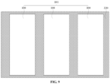
- FIG. 9 is a structural schematic diagram of a conveyor belt of the series welding machine with an arrangement of the plurality of solar cells being disposed on it according to some embodiments of the present disclosure.
- FIG. 10 is a structural schematic diagram of a strip-providing mechanism, a cutting mechanism and a transferring apparatus of the series welding machine according to some embodiments of the present disclosure. It should be noted that the complete transferring apparatus is not shown in FIG. 10 , it further includes a plurality of micro clips that are not shown.
- the series welding machine includes: a conveyor belt 220, an inspection apparatus (not shown), a welding mechanism, a strip-providing mechanism 230, a cutting mechanism 240, a strip-separating mechanism (not shown), and a transferring apparatus.
- the conveyor belt 220 is configured to carry a plurality of solar cells 100, such that an arrangement of the plurality of solar cells 101 is formed.
- the inspection apparatus is configured to perform inspections on the arrangement of the plurality of solar cells 101.
- the inspection apparatus includes a polarity inspection device configured to perform a plurality of polarity inspections on the arrangement of the plurality of solar cells 101.
- the welding mechanism includes a welding table 210 (referring to FIG.
- the strip-providing mechanism 230 is configured to provide a plurality of initial welding strips 111 arranged at intervals in a first direction X, each of the plurality of initial welding strips 111 extends in a second direction Y, the plurality of initial welding strips 111 include first initial welding strips and second initial welding strips, and the first initial welding strips interleave with the second initial welding strips in the first direction X.
- the cutting mechanism 240 is configured to cut each respective initial welding strip of the plurality of initial welding strips 111 along the first direction to obtain a plurality of welding strips 110.
- the cutting mechanism 240 includes a first cutting device 241 and a second cutting device 242.
- the first cutting device 241 is configured to cut each of the first initial welding strips 111 at one or more first cutting positions.
- the second cutting device 242 is configured to cut each of the second initial welding strips 111 at one or more second cutting positions that are offset from the one or more first cutting positions.
- the strip-separating mechanism is configured to move each welding strip of the plurality of welding strips 110 in the second direction Y to form the set of welding strips 114.
- the transferring apparatus is configured to transfer the set of welding strips 114 onto the arrangement of the plurality of solar cells 101, such that each welding strip 110 of the set of welding strips contacts with a peripheral solar cell 100 of the arrangement of the plurality of solar cells or with two respective adjacent solar cells 100 of the arrangement of the plurality of solar cells.
- the solar cells 100 may be arranged on the conveyor belt 220 to form the arrangement of the plurality of solar cells 101, and the inspection apparatus may be disposed over the conveyor belt 220.
- the arrangement of the plurality of solar cells 101 may be inspected using the inspection apparatus.
- the inspection apparatus may include a polarity inspection device and a visual inspection device configured to perform a plurality of visual inspections on the arrangement of the plurality of solar cells 101. When the polarity inspections by the polarity inspection device and the visual inspections by the visual inspection device all pass, the inspections performed on the arrangement of the plurality of solar cells are passed, and the arrangement of the plurality of solar cells 101 is obtained.
- the conveyor belt 220 may be connected to the welding mechanism, such that the arrangement of the plurality of solar cells 101 on the conveyor belt 220 is conveyed to the welding table 210 of the welding mechanism by the conveyor belt 220 for the subsequent welding operation.
- the strip-providing mechanism 230 can form the plurality of initial welding strips 111 arranged at intervals in the first direction X and extending in the second direction Y. During forming the plurality of initial welding strips 111, the strip-providing mechanism 230 may move along the second direction Y, such that the plurality of initial welding strips 111 extending in the second direction Y are formed with moving of the strip-providing mechanism.
- the cutting mechanism 240 may include a plurality of cutting knives disposed at different positions. It should be understood that the plurality of welding strips 110 in the cell string 102 are arranged in the interdigitated manner. In other words, in the first direction X, arrangement positions of the odd welding strips 110 are different from those of the even welding strips 110. Thus, the first cutting device 241 configured to cut each first initial welding strips 111 and the second cutting device 242 configured to cut each second initial welding strips 111 are provided, where the first cutting device 241 cut at one or more first cutting positions 112, and the second cutting device 242 cut at one or more second cutting positions 113 that are offset from the one or more first cutting positions 112.
- the one or more first cutting positions 112 and the one or more second cutting positions 113 may be set according to the arrangement of the plurality of welding strips in the cell string 102.
- One or more suitable first cutting positions 112 and one or more suitable second cutting positions 113 can reduce moving distance of the plurality of welding strips 110 during arrangement after cutting of the plurality of welding strips 110, thereby reducing the risk of the plurality of welding strips 110 being bent, and reducing the risk of deviation in welding of the plurality of welding strips 110 in the formed cell string 102.
- the strip-separating mechanism can move the plurality of welding strips 110 obtained by cutting in the second direction Y. Due to the fact that during forming the plurality of initial welding strips 111 by the strip-providing mechanism 230, a distance between each two initial welding strips 111 in the first direction X is equal to a distance between each two welding strips 110 in the cell string 102 in the first direction X, there is no need for the plurality of welding strips 110 to be moved in the first direction X after cutting, thereby reducing the risk of the plurality of welding strips 110 being bent.
- the first initial welding strips 111 and the second initial welding strips 111 have different cutting position respectively, depending on the arrangement positions of the plurality of welding strips 110 in the cell string 102, moving distance of the plurality of welding strips 110 during a strip-separating process can be reduced, thereby further reducing the risk of the plurality of welding strips 110 being bent, and reducing the possibility of deviation in welding of the plurality of welding strips 110 in the cell string 102.
- FIG. 11 is a structural schematic diagram of the micro clips of the series welding machine which clamp a welding strip for transferring according to some embodiments of the present disclosure.
- the transferring apparatus may include a plurality of micro clips 251 forming at least one set of micro clips 250.
- Micro clips 251 of one respective set of micro clips of the at least one set of micro clips are arranged in a line along the second direction Y.
- the plurality of micro clips 251 are configured to clamp the plurality of welding strips 110 for transferring the set of welding strips 114 onto the arrangement of the plurality of solar cells 101 by the transferring apparatus.
- the relative position relationship among the plurality of welding strips 110 of the set of welding strips 114 may be unchanged.
- each micro clip 251 of the plurality of micro clips 251 may have a same moving trajectory.
- each welding strip 110 of the set of welding strips are clamped and tensioned by at least two adjacent micro clips 251 of a respective set of micro clips 250 of the at least one set of micro clips.
- the two micro clips 251 clamp a same welding strip 110
- the two micro clips 251 are located in a same line along the second direction Y, and can tension the welding strip 110 in the second direction Y. In this way, the possible deformation of the welding strip 110 during the preceding strip-separating process can be reduced, thereby further reducing the risk of the welding strip 110 being bent, and reducing the possibility of deviation in welding of the welding strip 110 in the cell string 102.
- the series welding machine includes a conveyor belt configured to carry the arrangement of the plurality of solar cells, an inspection apparatus configured to perform inspections on the arrangement of the plurality of solar cells, a welding mechanism configured to weld a plurality of solar cells with a plurality of welding strips, a strip-providing mechanism configured to provide a plurality of initial welding strips, a cutting mechanism configured to cut the plurality of initial welding strips to obtain the plurality of welding strips, a strip-separating mechanism configured to move the plurality of welding strips, and a transferring apparatus configured to transfer the set of welding strips onto the arrangement of the plurality of solar cells, where the cutting mechanism includes a first cutting device configured to cut at one or more first cutting positions and a second cutting device configured to cut at one or more second cutting positions that are offset from the one or more first cutting positions.
Landscapes
- Engineering & Computer Science (AREA)
- Mechanical Engineering (AREA)
- Quality & Reliability (AREA)
- Physics & Mathematics (AREA)
- Optics & Photonics (AREA)
- Photovoltaic Devices (AREA)
- Connection Of Batteries Or Terminals (AREA)
Abstract
Embodiments of the present disclosure relate to the field of photovoltaics, and provide a method for welding cell strings and a series welding machine. The method for welding cell strings includes: providing a plurality of solar cells and forming an arrangement of the plurality of solar cells; performing inspections on the arrangement of the plurality of solar cells, in response to the inspections not passing, adjusting the arrangement of the plurality of solar cells until the plurality of polarity inspections pass; providing a plurality of initial welding strips arranged at intervals in a first direction and extending in a second direction, the plurality of initial welding strips include first initial welding strips and second initial welding strips, and the first initial welding strips interleave with the second initial welding strips in the first direction; cutting the plurality of initial welding strips to obtain a plurality of welding strips, where each of the first initial welding strips is cut at one or more first cutting positions, and each of the second initial welding strips is cut at one or more second cutting positions; moving each welding strip in the second direction to form a set of welding strips having a spacing between each two adjacent welding strips of the plurality of welding strips in the second direction; transferring the set of welding strips onto the arrangement of the plurality of solar cells; and welding the plurality of welding strips to corresponding solar cells of the arrangement of the plurality of solar cells to form a cell string. The method is at least conducive to address the problem of the welding strips being bent or deviation in welding of the welding strips.
Description
- Embodiments of the present disclosure relate to the field of photovoltaics, and in particular to a method for welding cell strings and a series welding machine.
- An interdigitated back-contact (IBC) solar cell refers to a solar cell having a structure in which positive and negative metal electrodes are formed in an interdigitated pattern on a back surface of the solar cell and are in contact with junctions formed on the back surface. The PN junctions and the electrodes of this solar cell are disposed on the back surface of the solar cell, i.e. the electrodes for emission regions and base regions of the IBC cell are all formed on the back surface, and there are no gird lines on a front surface. In this way, the performance of photoelectric conversion of the solar cell can be improved.
- IBC cells may be series welded into a cell string in a following way: the cells are arranged in sequence with back surfaces facing upwards, and each two adjacent cells have opposite polarities. Then a plurality of cells are welded using a set of interdigitated welding strips to obtain the cell string. However, some welding strips of the set of interdigitated welding strips are highly likely to be bent, and the welding strips are prone to deformation, thereby leading to deviation in welding.
- Embodiments of the present disclosure provide a method for welding cell strings and a series welding machine, which are at least conducive to address the problems of welding strips being bent and deviation in welding.
- Some embodiments of the present disclosure provide a method for welding a cell string, including:
- providing a plurality of solar cells and forming an arrangement of the plurality of solar cells;
- performing inspections on the arrangement of the plurality of solar cells, where the inspections include a plurality of polarity inspections, in response to the plurality of polarity inspections not passing, adjusting the arrangement of the plurality of solar cells until the plurality of polarity inspections pass;
- in response to the plurality of polarity inspections passing:
- placing the arrangement of the plurality of solar cells on a welding table;
- providing a plurality of initial welding strips arranged at intervals in a first direction, each of the plurality of initial welding strips extends in a second direction, the plurality of initial welding strips include first initial welding strips and second initial welding strips, and the first initial welding strips interleave with the second initial welding strips in the first direction;
- cutting each respective initial welding strip of the plurality of initial welding strips along the first direction to obtain a plurality of welding strips, each of the first initial welding strips is cut at one or more first cutting positions, and each of the second initial welding strips is cut at one or more second cutting positions that are offset from the one or more first cutting positions;
- moving each welding strip of the plurality of welding strips in the second direction to form a set of welding strips having a spacing between each two adjacent welding strips of the plurality of welding strips in the second direction;
- transferring the set of welding strips onto the arrangement of the plurality of solar cells, and arranging the plurality of welding strips such that each welding strip of the plurality of welding strips contacts with a peripheral solar cell of the arrangement of the plurality of solar cells or with two respective adjacent solar cells of the arrangement of the plurality of solar cells; and
- welding each welding strip of the plurality of welding strips to the peripheral solar cell of the arrangement of the plurality of solar cells or to the two respective adjacent solar cells of the arrangement of the plurality of solar cells, to form a cell string.
- In some embodiments, a distance between one respective first cutting position of the one or more first cutting positions and one respective second cutting position of the one or more second cutting positions adjacent to the one respective first cutting position in the second direction ranges from 50mm to 110mm.
- In some embodiments, the spacing between each two adjacent welding strips of the plurality of welding strips in the second direction ranges from 8mm to 15mm.
- In some embodiments, the inspections further include a plurality of visual inspections, and in response to both the plurality of polarity inspections and the plurality of visual inspections passing, the inspections are passed. Performing the plurality of visual inspections on the arrangement of the plurality of solar cells, includes: performing a visual inspection on each respective solar cell of the arrangement of the plurality of solar cells; in response to the visual inspection of the each respective solar cell passing, determining that the plurality of visual inspections of the arrangement of the plurality of solar cells are passed; in response to the visual inspection of any one solar cell of the arrangement of the plurality of solar cells not passing, determining that the plurality of visual inspections of the arrangement of the plurality of solar cells are not passed, and replacing one or more solar cells whose visual inspections are not passed with new one or more solar cells, where each solar cell of the new one or more solar cells has a polarity same as a polarity of a respective solar cell of replaced one or more solar cells; and performing the plurality of visual inspections on the arrangement of the plurality of solar cells again, until the plurality of visual inspections of the arrangement of the plurality of solar cells are passed.
- In some embodiments, performing the plurality of polarity inspections on the arrangement of the plurality of solar cells, includes: performing a polarity inspection on each respective solar cell of the arrangement of the plurality of solar cells; in response to any two adjacent solar cells of the arrangement of the plurality of solar cells having different polarities, determining that the plurality of polarity inspections of the arrangement of the plurality of solar cells are passed; and in response to any two adjacent solar cells of the arrangement of the plurality of solar cells having a same polarity, determining that the plurality of polarity inspections of the arrangement of the plurality of solar cells are not passed, and removing one solar cell of each two adjacent solar cells of the arrangement of the plurality of solar cells having a same polarity.
- In some embodiments, before transferring the set of welding strips onto the arrangement of the plurality of solar cells, the method further includes: providing a press tooling and placing the press tooling on the set of welding strips; and transferring the set of welding strips onto the arrangement of the plurality of solar cells, further includes: transferring the set of welding strips together with the press tooling onto the arrangement of the plurality of solar cells.
- In some embodiments, the plurality of solar cells are back-contact solar cells.
- Some embodiments of the present disclosure provide a series welding machine, including:
- a conveyor belt, configured to carry a plurality of solar cells, such that an arrangement of the plurality of solar cells is formed;
- an inspection apparatus, configured to perform inspections on the arrangement of the plurality of solar cells, where the inspection apparatus includes a polarity inspection device configured to perform a plurality of polarity inspections on the arrangement of the plurality of solar cells;
- a welding mechanism, including a welding table and configured to weld the arrangement of the plurality of solar cells with a set of welding strips;
- a strip-providing mechanism, configured to provide a plurality of initial welding strips arranged at intervals in a first direction, each of the plurality of initial welding strips extends in a second direction, the plurality of initial welding strips include first initial welding strips and second initial welding strips, and the first initial welding strips interleave with the second initial welding strips in the first direction;
- a cutting mechanism, configured to cut each respective initial welding strip of the plurality of initial welding strips along the first direction to obtain a plurality of welding strips, the cutting mechanism includes:
- a first cutting device, configured to cut each of the first initial welding strips at one or more first cutting positions; and
- a second cutting device, configured to cut each of the second initial welding strips at one or more second cutting positions that are offset from the one or more first cutting positions;
- a strip-separating mechanism, configured to move each welding strip of the plurality of welding strips in the second direction to form the set of welding strips; and
- a transferring apparatus, configured to transfer the set of welding strips onto the arrangement of the plurality of solar cells, such that each welding strip of the plurality of welding strips contacts with a peripheral solar cell of the arrangement of the plurality of solar cells or with two respective adjacent solar cells of the arrangement of the plurality of solar cells.
- In some embodiments, the transferring apparatus includes: a plurality of micro clips forming at least one set of micro clips, where micro clips of one respective set of micro clips of the at least one set of micro clips are arranged in a line along the second direction, and the plurality of micro clips are configured to clamp the plurality of welding strips for transferring the set of welding strips onto the arrangement of the plurality of solar cells.
- In some embodiments, during transferring the set of welding strips onto the arrangement of the plurality of solar cells by the transferring apparatus, each welding strip of the set of welding strips are clamped and tensioned by at least two adjacent micro clips of a respective set of micro clips of the at least one set of micro clips.
- One or more embodiments are exemplarily illustrated in reference to corresponding accompanying drawing(s), and these exemplary illustrations do not constitute limitations on the embodiments. Unless otherwise stated, the accompanying drawings do not constitute scale limitations. In order to illustrate the technical solutions in related technologies or in the embodiments of the present disclosure more clearly, the drawings to be used in the description of the embodiments will be briefly described below. It is obvious that the drawings mentioned in the following description are only some embodiments of the present disclosure. For those of ordinary skill in the art, other drawings may also be obtained in accordance with these drawings without any inventive effort.
-
FIG. 1 is a flow chart of a method for welding cell strings according to some embodiments of the present disclosure. -
FIGS. 2 to 8 are structural schematic diagrams corresponding to operations of the method for welding cell strings according to some embodiments of the present disclosure. -
FIG. 9 is a structural schematic diagram of a conveyor belt of a series welding machine according to some embodiments of the present disclosure. -
FIG. 10 is a structural schematic diagram of a strip-providing mechanism, a cutting mechanism and a transferring apparatus of the series welding machine according to some embodiments of the present disclosure. -
FIG. 11 is a structural schematic diagram of the transferring apparatus of the series welding machine according to some embodiments of the present disclosure. - When a certain part "includes" another part throughout the specification, other parts are not excluded unless otherwise stated, and other parts may be further included. In addition, when parts such as a layer, a film, a region, or a plate is referred to as being "on" another part, it may be "directly on" another part or may have another part present therebetween. In addition, when a part of a layer, film, region, plate, etc., is "directly on" another part, it means that no other part is positioned therebetween.
- The terminology used in the description of the various described embodiments herein is for the purpose of describing particular embodiments only and is not intended to be limiting. As used in the description of the various described embodiments and the appended claims, the singular forms "a", "an" and "the" are intended to include the plural forms as well, unless the context clearly indicates otherwise.
- It can be known from the background art that the existing method for welding cell strings risks that welding strips are likely to be bent, leading to deviation in welding.
- In related technologies, during arranging welding strips, a drawing apparatus for welding strips is used to draw a plurality of welding strips in an interdigitated manner. Firstly, a plurality of welding strips spaced from each other are arranged in corresponding positions, and then are laid on solar cells. Secondly, a plurality of remaining welding strips are drawn and arranged in corresponding positions, and then are laid on the solar cells. Finally, the set of welding strips which is arranged in the interdigitated manner is welded to the arrangement of the plurality of solar cells to form a cell string. During the plurality of welding strips are drawn by the drawing apparatus for welding strips and are arranged in the interdigitated manner, due to the small widths and low hardness of the welding strips, the welding strips are very likely to be bent, resulting in deviations in welding of the welding strips in the obtained cell string.
- In the embodiments of the present disclosure, on the one hand, all initial welding strips are cut and arranged concurrently to form the overall set of welding strips, without need of processing the initial welding strips singly, thereby improving production efficiency. On the other hand, during cutting of the plurality of initial welding strips, cutting positions of first initial welding strips are different from cutting positions of second initial welding strips of the plurality of initial welding strips. In other words, each two adjacent initial welding strips of the plurality of initial welding strips have different cutting positions. The cutting positions are adaptive to arrangement positions of welding strips to be determined in a subsequent arrangement process. Thus, cutting at suitable positions can reduce moving distance of each welding strip in the subsequent process, and can reduce strokes of the strip-separating mechanism. In this way, the risk of the welding strips being bent and the possibility of deviations in welding can be reduced. Moreover, in embodiments of the present disclosure, inspections are performed on solar cells during arrangement of the solar cells, thereby reducing the risk of defective solar cells and improving yield of products.
- Some embodiments of the present disclosure provide a method for welding a cell string. A plurality of solar cells are arranged to form an arrangement of the plurality of solar cells, and inspections are performed on the arrangement of the plurality of solar cells. In response to the inspections passing, the arrangement of the plurality of solar cells is placed on a welding table. A plurality of initial welding strips are provided and cut, where each of first initial welding strips of the plurality of initial welding strips is cut at one or more first cutting positions, and each of second initial welding strips of the plurality of initial welding strips is cut at one or more second cutting positions that are offset from the one or more first cutting positions. Each welding strip of the plurality of welding strips obtained by cutting is moved to form a set of welding strip. The set of welding strips is transferred onto and welded with the arrangement of the plurality of solar cells to form a cell string. In this way, the initial welding strips arranged in the interdigitated manner are cut and arranged concurrently, thereby improving production efficiency. On the other hand, different initial welding strips are cut at different cutting positions, thereby reducing distances in the strip-separating process. In this way, the risk of the welding strips being bent and the possibility of deviations in welding can be reduced. Moreover, inspections performed on the arrangement of the plurality of solar cells can reduce the risk of defective solar cells and improve yield of products.
- In order to make the purposes, technical solutions and advantages of the embodiments of the present disclosure more clearly, the embodiments of the present disclosure will be described in detail below with reference to the accompanying drawings. Those skilled in the art should understand that, in the embodiments of the present disclosure, many technical details are provided for the reader to better understand the present disclosure. However, even without these technical details and various modifications and variants based on the following embodiments, the technical solutions claimed in the present disclosure can be implemented.
- Referring to
FIGS. 1 and2 , at S 1, a plurality ofsolar cells 100 are provided and form an arrangement of the plurality ofsolar cells 101. - In some embodiments, the provided plurality of
solar cells 100 may be back-contact cells. The provided plurality ofcells 100 may be interdigitated back contact (IBC) cells. Contact electrodes of an IBC cell which are in an interdigital form and contact with at least one PIN junction, a substrate, and at least one emitter region are formed on the back surface of the cell. A p+ region is formed by printing an interdigital diffusion mask layer containing boron on the back surface of the cell and by diffusion of the boron in the mask layer into the N-type substrate, and an n+ region is formed by diffusion of phosphorus in a region on which the mask layer is not printed. The grid lines of the IBC cell are all formed on the back surface of the cell, and there is no grid line on the front surface of the cell, which may eliminate the loss of current due to blocking of light by the metal electrodes and achieve maximum utilization of incident photons. Compared with conventional solar cells, the short-circuit current of an IBC cell may be increased by about 7%. Due to the back-contact structure of the IBC cells, there is no concern on blocking of gird lines, and scales of the gird lines may be appropriately increased to reduce series resistance. Moreover, surface passivation and surface trapping structures may be optimized, to obtain lower recombination rate on the front surface and lower surface reflection. Furthermore, the IBC cells have beautiful appearance, and are especially suitable for the integration of photovoltaic modules and buildings. - It can be known from above that during forming a cell string with back-contact cells, the welding strips used to connect the
cells 100 are welded to the back surfaces of thecells 100. Moreover, during forming the arrangement of the plurality ofsolar cells 101, the arrangement of the plurality ofsolar cells 101 is arranged such that any two adjacentsolar cells 100 of the arrangement of the plurality ofsolar cells 101 have opposite polarities. Herein, the expression "any two adjacent solar cells have opposite polarities" refers that the two solar cells are arranged such that a p+ region of one solar cell is adjacent to an n+ region of the other solar cell, or an n+ region of one solar cell is adj acent to a p+ region of the other solar cell. Similarly, the expression "any two adjacent solar cells have a same polarity" refers that the two solar cells are arranged such that the p+ region of one solar cell is adjacent to the p+ region of the other solar cell, or the n+ region of one solar cell is adjacent to the n+ region of the other solar cell. - It should be noted that
FIG. 2 only shows threesolar cells 100 of the arrangement of the plurality ofsolar cells 101, and is not intended to limit the number ofsolar cells 100 of an actual arrangement of the plurality ofsolar cells 101. In an actual production process, there may be a plurality ofsolar cells 100 in the arrangement of the plurality ofsolar cells 101. - Referring to
FIGS. 1 and2 , at S2, inspections are performed on the arrangement of the plurality ofsolar cells 101, where the inspections include a plurality of polarity inspections, in response to the plurality of polarity inspections not passing, adjusting the arrangement of the plurality ofsolar cells 101 until the plurality of polarity inspections pass. - In some embodiments, performing the plurality of polarity inspections on the arrangement of the plurality of
solar cells 101 may include: performing a polarity inspection on each respectivesolar cell 100 of the arrangement of the plurality ofsolar cells 101; in response to any two adjacentsolar cells 100 of the arrangement of the plurality of solar cells having different polarities, determining that the plurality of polarity inspections of the arrangement of the plurality of solar cells are passed; and in response to any two adjacentsolar cells 100 of the arrangement of the plurality of solar cells having a same polarity, determining that the plurality of polarity inspections of the arrangement of the plurality of solar cells are not passed, and removing onesolar cell 100 of each two adjacentsolar cells 100 of the arrangement of the plurality of solar cells having a same polarity. Any two adjacentsolar cells 100 of the arrangement of the plurality ofsolar cells 101 whose polarity inspections pass have different polarities. In this way, a decrease in yield of the formed cell string due to the presence of adjacentsolar cells 100 having a same polarity in the arrangement of the plurality ofsolar cells 101 can be prevented. When there are one or more polarity inspections which are not passed during the polarity inspections, it indicates that there are adjacentsolar cells 100 having a same polarity. In this case, the arrangement of the plurality ofsolar cells 101 may be adjusted by removing one of the adjacentsolar cells 100 having a same polarity. - The polarity inspections may include: a first
solar cell 100 of the arrangement of the plurality ofsolar cells 101 to be arranged is inspected to obtain a polarity of the firstsolar cell 100; a secondsolar cell 100 to be arranged is inspected to obtain a polarity of the secondsolar cell 100; it is determined whether the polarity of the firstsolar cell 100 is the same as the polarity of the secondsolar cell 100, in response to the polarity of the firstsolar cell 100 being the same as the polarity of the secondsolar cell 100, the secondsolar cell 100 is removed and a thirdsolar cell 100 is taken as a new secondsolar cell 100, and the above inspections are repeated. In response to the polarity of the firstsolar cell 100 being not the same as the polarity of the secondsolar cell 100, a thirdsolar cell 100 is inspected to obtain a polarity of the thirdsolar cell 100, and it is determined whether the polarity of the thirdsolar cell 100 is the same as the polarity of the secondsolar cell 100, until allsolar cells 100 of the arrangement of the plurality ofsolar cells 101 are inspected. When the plurality of polarity inspections are completed and passed, any two adjacentsolar cells 100 of the arrangement of the plurality ofsolar cells 101 have different polarities. - In some embodiments, performing inspections on the arrangement of the plurality of
solar cells 101 may further include: performing a plurality of visual inspections on the arrangement of the plurality of solar cells, and in response to both the plurality of polarity inspections and the plurality of visual inspections passing, the inspections are passed. It can be determined whether thesolar cells 100 are defective, or whether there are scratches, cracks, and the like in the solar cells by the plurality of visual inspections. The plurality of visual inspections can ensure that eachsolar cell 100 of the arrangement of the plurality ofsolar cells 101 has high quality, thereby preventing the occurrence of substandardsolar cells 100 in the arrangement of the plurality ofsolar cells 101, and effectively improving the yield of the formed cell string. In addition, the inspections performed on the arrangement of the plurality ofsolar cells 101 may further include other types of inspections, and only when all inspections pass, the inspections performed on the arrangement of the plurality ofsolar cells 101 pass. When any one inspection does not pass, the arrangement of the plurality ofsolar cells 101 shall be accordingly adjusted. - In some embodiments, performing the plurality of visual inspections on the arrangement of the plurality of
solar cells 101 may include: performing a visual inspection on each respectivesolar cell 100 of the arrangement of the plurality ofsolar cells 101; in response to the visual inspection of the each respectivesolar cell 100 passing, determining that the plurality of visual inspections of the arrangement of the plurality ofsolar cells 101 are passed, and in response to the visual inspection of any onesolar cell 100 of the arrangement of the plurality of solar cells not passing, determining that the plurality of visual inspections of the arrangement of the plurality ofsolar cells 101 are not passed; replacing one or moresolar cells 100 whose visual inspections are not passed with new one or moresolar cells 100, where each solar cell of the new one or moresolar cells 100 has a polarity same as a polarity of a respective solar cell of replaced one or moresolar cells 100; and performing the plurality of visual inspections on the arrangement of the plurality ofsolar cells 101 again, until the plurality of visual inspections are passed. In this way, eachsolar cell 100 of the arrangement of the plurality ofsolar cells 101 can be subjected to a visual inspection, such that eachsolar cell 100 of the arrangement of the plurality ofsolar cells 101 can be a qualifiedsolar cell 100, thereby effectively improving the yield of the cell string. Anysolar cell 100 whose visual inspection is not passed is replaced with a newsolar cell 100, and the newsolar cell 100 has a polarity same as a polarity of the replacedsolar cell 100, in order to ensure that any two adjacentsolar cells 100 of the arrangement of the plurality ofsolar cells 101 still have opposite polarities. - Referring to
FIGS. 1 and3 , at S3, the arrangement of the plurality ofsolar cells 101 is placed on a welding table 210. The welding table 210 is an apparatus used for welding the arrangement of the plurality ofsolar cells 101 with welding strips. The arrangement of the plurality ofsolar cells 101 after adjustment and inspections may be placed on the welding table 210 for subsequent welding. - After the adjustment and placement of the arrangement of the plurality of
solar cells 101, or during the adjustment and placement of the arrangement of the plurality ofsolar cells 101, the welding strips for welding the solar cells may be produced. Producing the welding strips during the adjustment and placement of the arrangement of the plurality ofsolar cells 101 can reduce production time and improve production efficiency. - Referring to
FIGS. 1 and4 , at S4, a plurality of initial welding strips 111 arranged at intervals in a first direction X are provided, where each of the plurality of initial welding strips 111 extends in a second direction Y, the plurality of initial welding strips 111 include first initial welding strips and second initial welding strips, and the first initial welding strips interleave with the second initial welding strips in the first direction X. After processing, aninitial welding strip 111 may be transformed into a plurality of welding strips 110 in a same line along the second direction Y in the cell string. In the first direction X, a width of aninitial welding strip 111 is the same as that of awelding strip 110 used in the cell string. Moreover, in the first direction X, a distance between adjacent initial welding strips 111 is the distance between adjacent welding strips 110 in the cell string. During producing the initial welding strips 111 into the welding strips 110, there is no need to move the welding strips 110 in the first direction X, which can reduce the risk of bending of the welding strips 110 due to movement of the welding strips 110. - Referring to
FIGS. 1 and5 , at S5, each respective initial welding strip of the plurality of initial welding strips 111 is cut along the first direction to obtain a plurality of welding strips 110. Each of the first initial welding strips 111 is cut at one or more first cutting positions 112, and each of the second initial welding strips 111 is cut at one or more second cutting positions 113 that are offset from the one or more first cutting positions 112. - In the cell string, the plurality of welding strips 110 which are used to connect the plurality of
solar cells 100 to form the cell string are arranged in the interdigitated manner, in other words, the arrangement positions of the welding strips 110 located in adjacent lines in the first direction X are different, and the arrangement positions of the welding strips 110 located in each two lines separated in the first direction X and with another line between them are the same. Thus, in the first direction X, the first initial welding strips 111 of the plurality of initial welding strips have the same arrangement positions, and the second initial welding strips 111 of the plurality of initial welding strips have the same arrangement positions. Therefore, when cutting the plurality of initial welding strips 111 to obtain the plurality of welding strips 110, the first initial welding strips 111 and the second initial welding strips 111 may be cut at different cutting positions, and the cutting positions may be set according to the arrangement positions of the welding strips 111 in the cell string. In this way, during arrangement of the welding strips 110 obtained by cutting, moving distance of each welding strip can be effectively reduced, thereby reducing bending of the welding strips 110 occurred in strip-separating process, and reducing the risk of deviation in welding in the cell string. - In some embodiments, each first cutting position of the one or more first cutting positions 112 may align with a respective second cutting position of the one or more second cutting positions 113 in the first direction. In this way, the cutting mechanism for the initial welding strips 111 can be simplified to a certain extent, thereby reducing production costs.
- Referring to
FIG. 5 , in some embodiments, the one or more first cutting positions 112 are different from the one or more second cutting positions 113, and a distance between one respective first cutting position of the one or more first cutting positions 112 and one respective second cutting position of the one or more second cutting positions 113 adjacent to the one respective first cutting position in the second direction Y ranges from 50mm to 110mm. For example, a distance between afirst cutting position 112 and asecond cutting position 113 adjacent to thefirst cutting position 112 in the second direction Y may be 50mm, 70mm, 90mm, 100mm, 110mm, or the like. The distance between adjacent cutting positions is as shown in the drawing. If the distance between thefirst cutting position 112 and thesecond cutting position 113 adjacent to thefirst cutting position 112 in the second direction Y is too small, the welding strips 110 obtained by cutting the first initial welding strips 111 and/or the welding strips 110 obtained by cutting the second initial welding strips 111 have to be moved for relatively long distances to implement the interdigitated arrangement of the plurality of welding strips 110. Thus, the strip-separating distances are increased, thereby increasing the risk of bending of the welding strips 110 during the strip-separating process, and increasing the risk of deviation in welding in the formed cell string. If the distance between thefirst cutting position 112 and thesecond cutting position 113 adjacent to thefirst cutting position 112 in the second direction Y is too large, the welding strips 110 still have to be moved for relatively long distances to implement the interdigitated arrangement of the plurality of welding strips 110. Thus, the strip-separating distances are increased, thereby increasing the risk of bending of the welding strips 110 during the strip-separating process, and increasing the risk of deviation in welding in the formed cell string. Therefore, a suitable range of the distance between thefirst cutting position 112 and thesecond cutting position 113 adjacent to thefirst cutting position 112 in the second direction Y is selected, and the distance between adjacent cutting positions may be selected according to the arrangement of the welding strips 111 in the cell string. When the distance between thefirst cutting position 112 and thesecond cutting position 113 adjacent to thefirst cutting position 112 in the second direction Y ranges from 50mm to 110mm, moving distance of eachwelding strip 110 can be effectively reduced, thereby reducing risk of bending of the welding strips 110 during strip-separating process, and reducing the risk of deviation in welding in the formed cell string. - Referring to
FIGS. 1 and6 , at S6, eachwelding strip 110 of the plurality of welding strips is moved in the second direction Y to form a set of welding strips 114 having a spacing between each two adjacent welding strips 110 of the plurality of welding strips in the second direction Y. The arrangement of the set of welding strips 114 refers to the arrangement of the plurality of welding strips 110 in thecell string 102. The positions of the plurality of welding strips 110 to be used in the cell string are arranged in advance, and the arranged set of welding strips 114 is transferred to the arrangement of the plurality ofsolar cells 101. In this way, moving distance of eachwelding strip 110 during the strip-separating process for interdigitated arrangement can be reduced, thereby reducing risk of bending of the welding strips 110. - Due to the fact that the distances between the plurality of initial welding strips 111 formed in the preceding operations in the first direction X are the same as the distances between adjacent welding strips 110 in the first direction X in the cell string, when moving the welding strips 110, the welding strips 110 are not moved in the first direction X, but only are moved in the second direction Y, which can reduce the risk of bending of the welding strips 110 during movement. Because during cutting of the welding strips 110, the welding strips 110 spaced from each other in the first direction X and having different arrangement positions in the cell string have different cutting positions, the moving distance of each
welding strip 110 in the second direction Y can be reduced, thereby further reducing risk of bending of the welding strips 110 during movement, and reducing the risk of deviation in welding in the formed cell string. - Referring to
FIG. 6 , in some embodiments, after movement of each welding strips 110 in the second direction Y, the spacing between each two adjacent welding strips 110 of the plurality of welding strips in the second direction Y ranges from 8mm to 15mm. The spacing between two adjacent welding strips 110 in the second direction Y is shown in the drawing. For example, the spacing between two adjacent welding strips 110 in the second direction Y after movement may be 5mm, 9mm, 10mm, 12mm, 15mm, and the like. The spacing between two adjacent welding strips 110 in the second direction Y after movement may be set according to the arrangement of the cell string. If the spacing between two adjacent welding strips 110 in the second direction Y is too small, then in the cell string formed by welding in subsequent operations, a spacing between adjacentsolar cells 100 is small, and there is a risk of short circuit between adjacentsolar cells 100, which will reduce the reliability of the cell string to a certain extent. If the spacing between two adjacent welding strips 110 in the second direction Y is too large, then in the cell string formed by welding in subsequent operations, the spacing between adjacentsolar cells 100 is larger, and the overall size of the cell string is also larger, which will cause the size of the photovoltaic module made by the cell strings to be too large, thereby affecting the use of the product and causing material waste. Therefore, a suitable range of the spacing between two adjacent welding strips 110 in the second direction Y after movement is selected. When the spacing between two adjacent welding strips 110 in the second direction Y ranges from 8mm to 15mm, it will not cause a significant risk of short circuit in the cell string, nor cause a too large size of the cell string, thus no influence is brought to the use of the products. - In some embodiments, before transferring the set of welding strips 114 onto the arrangement of the plurality of
solar cells 101, the method may further include: providing a press tooling (not shown in drawings) and placing the press tooling on the set of welding strips 114. The press tooling is a tooling apparatus and may be configured to press the set of welding strips 114 arranged in the preceding operations. Placing the press tooling on the set of welding strips 114 can press all the welding strips 110 of the set of welding strips 114 onto a same plane, which enables the welding strips 110 of the set of welding strips 114 to better contact with the surfaces of thesolar cells 100 of the arrangement of the plurality ofsolar cells 101 after moving the set of welding strips 114 onto the arrangement of the plurality ofsolar cells 101, which is conducive to the subsequent welding operations. - Transferring the set of welding strips 114 onto the arrangement of the plurality of
solar cells 101 may further includes: transferring the set of welding strips together with the press tooling onto the arrangement of the plurality ofsolar cells 101. The press tooling is configured to press all the welding strips 110 of the set of welding strips 114. Transferring the set of welding strips 114 together with the press tooling onto the arrangement of the plurality ofsolar cells 101 not only enables the welding strips 110 of the set of welding strips 114 to have better contact with the surfaces of thesolar cells 100 of the arrangement of the plurality ofsolar cells 101, but also prevents the displacement of the arrangement of the welding strips 110 of the set of welding strips 114 during transferring the set of welding strips 114. - Referring to
FIGS. 1 and7 , at S7, the set of welding strips 114 is transferred onto the arrangement of the plurality ofsolar cells 101 such that eachwelding strip 110 of the set of welding strips 114 contacts with a peripheralsolar cell 100 of the arrangement of the plurality of solar cells or with two respective adjacentsolar cells 100 of the arrangement of the plurality of solar cells. During transferring the set of welding strips 114 onto the arrangement of the plurality ofsolar cells 101, the relative position relationships among the welding strips 110 of the set of welding strips 114 do not change, and the relative position relationships among the welding strips 110 of the set of welding strips 114 which are in the interdigitated arrangement are formed only by the above strip-separating operation. The transferring process does not change the relative position relationships in the set of welding strips 114, nor cause bending of the welding strips 110 due to moving the welding strips 110 on a horizontal plane. Thus, the relative positions of the welding strips 110 are arranged first, and then the arranged set of welding strips 114 is transferred as a whole onto the arrangement of the plurality ofsolar cells 101, in this way, the moving distances of the welding strips 110 on the horizontal plane for the interdigitated arrangement can be effectively reduced, and the risk of the welding strips 110 being bent can be reduced. - Before transferring the set of welding strips 114, the arrangement of the plurality of
solar cells 101 is located on the welding table 210. Thus, transferring the set of welding strips 114 onto the arrangement of the plurality ofsolar cells 101 means transferring the set of welding strips 114 onto the welding table 210 too, which facilitates the subsequent welding operation of welding the arrangement of the plurality ofsolar cells 101 with the set of welding strips 114 to form the cell string. After the set of welding strips 114 is transferred onto the arrangement of the plurality ofsolar cells 101, the welding strips 110 not located on peripheries of the set of welding strips in the second direction Y may connect two adjacentsolar cells 100, and in the first direction X, each welding strip of the odd welding strips 110 connect two adjacentsolar cells 100 different from those connected by each welding strip of the even welding strips 110. The welding strips 110 located on peripheries of the set of welding strips in the second direction Y may only connect to a peripheralsolar cell 100. In addition, one end of one respective welding strip of the welding strips 110 located on peripheries of the set of welding strips in the second direction Y is connected to the peripheralsolar cell 100, the other end of the one respective welding strip may extend outside the peripheralsolar cell 100 for electrical connection with other structures. - In some embodiments, during transferring the set of welding strips 114, the welding strips 110 of the set of welding strips 114 may be tensioned. In this way, the possible deformation occurred during movement of the welding strips 110 for the interdigitated arrangement can be reduced, thereby further reducing the risk of the welding strips 110 being bent and the possibility of deviations in welding of the welding strips 110 in the cell string.
- Referring to
FIGS. 1 and7 , at S8, eachwelding strip 110 of the plurality of welding strips 110 is welded to the peripheralsolar cell 100 of the arrangement of the plurality ofsolar cells 101 or to the two respective adjacentsolar cells 100 of the arrangement of the plurality ofsolar cells 101, to form thecell string 102. The plurality of welding strips 110 can electrically connect with the arrangement of the plurality ofsolar cells 101, such that the arrangement of the plurality ofsolar cells 101 can formed thecomplete cell string 102. Compared with individualsolar cell 100, thecell string 102 can achieve better power supply capacity and higher performance. Due to the fact that both the set of welding strips 114 and the arrangement of the plurality ofsolar cells 101 are located on thewelding station 210, thewelding station 210 may be directly used to weld the arrangement of the plurality ofsolar cells 101 and the set of welding strips 114. - It should be noted that the drawings only show a
cell string 102 having threesolar cells 100, which does not represent the actual number of thesolar cells 100 of thecell string 102. In anactual cell string 102, there may be a plurality ofsolar cells 100. - Referring to
FIG. 8 , after forming thecell string 102 by welding, a plurality ofcell strings 102 may be connected to form a set of cell strings 103. The structures that connect the plurality ofcell strings 102 may be bus bars. It should be noted that the drawings only show the set ofcell strings 103 formed by connecting twocell strings 102, which does not represent the actual number of the cell strings 102 of the set of cell strings 103. In an actual set ofcell strings 103, there may be a plurality of cell strings 102. - In some embodiments, connecting a plurality of
cell strings 102 to form the set ofcell strings 103 may include a connection method of AB strings, where A refers to a positive pole of acell string 102, B refers to a negative pole of anothercell string 102, and AB strings refer to connecting the positive pole to the negative pole. In this way, the output voltage and power of the set ofcell strings 103 can be increased, and current loss can be reduced. - Some embodiments of the present disclosure provide a method for welding a cell string. A plurality of solar cells are provided and arranged to form an arrangement of the plurality of solar cells, and inspections are performed on the arrangement of the plurality of solar cells. In response to the inspections passing, the arrangement of the plurality of solar cells is placed on a welding table. A plurality of initial welding strips are provided and cut to obtain a plurality of welding strips, where each of first initial welding strips of the plurality of initial welding strips is cut at one or more first cutting positions, and each of second initial welding strips of the plurality of initial welding strips is cut at one or more second cutting positions that are offset from the one or more first cutting positions. Each welding strip of the plurality of welding strips is moved in the second direction to form a set of welding strips. The set of welding strips is transferred onto the arrangement of the plurality of solar cells and is welded to form the cell string. In this way, all welding strips are processed concurrently, thereby improving production efficiency. On the other hand, different initial welding strips are cut at different cutting positions, distances in the strip-separating process can be reduced, thereby reducing the risk of the welding strips being bent and the possibility of deviations in welding. Moreover, inspections are performed on the arrangement of the plurality of solar cells, thus the yield of products can be improved.
- Some embodiments of the present disclosure provide a series welding machine applicable to implement the method for welding cell strings as described above. The following will provide a detailed description of the series welding machine provided by some embodiments of the present disclosure in conjunction with the accompanying drawings. The same or corresponding parts as the preceding embodiments may be referred to in the corresponding description of the aforementioned embodiments, and will not be described in detail below.
-
FIG. 9 is a structural schematic diagram of a conveyor belt of the series welding machine with an arrangement of the plurality of solar cells being disposed on it according to some embodiments of the present disclosure.FIG. 10 is a structural schematic diagram of a strip-providing mechanism, a cutting mechanism and a transferring apparatus of the series welding machine according to some embodiments of the present disclosure. It should be noted that the complete transferring apparatus is not shown inFIG. 10 , it further includes a plurality of micro clips that are not shown. - Referring to
FIGS. 9 and10 , the series welding machine includes: aconveyor belt 220, an inspection apparatus (not shown), a welding mechanism, a strip-providingmechanism 230, acutting mechanism 240, a strip-separating mechanism (not shown), and a transferring apparatus. Theconveyor belt 220 is configured to carry a plurality ofsolar cells 100, such that an arrangement of the plurality ofsolar cells 101 is formed. The inspection apparatus is configured to perform inspections on the arrangement of the plurality ofsolar cells 101. The inspection apparatus includes a polarity inspection device configured to perform a plurality of polarity inspections on the arrangement of the plurality ofsolar cells 101. The welding mechanism includes a welding table 210 (referring toFIG. 3 ) and is configured to weld the arrangement of the plurality ofsolar cells 101 with a set of welding strips 114. The strip-providingmechanism 230 is configured to provide a plurality of initial welding strips 111 arranged at intervals in a first direction X, each of the plurality of initial welding strips 111 extends in a second direction Y, the plurality of initial welding strips 111 include first initial welding strips and second initial welding strips, and the first initial welding strips interleave with the second initial welding strips in the first direction X. Thecutting mechanism 240 is configured to cut each respective initial welding strip of the plurality of initial welding strips 111 along the first direction to obtain a plurality of welding strips 110. Thecutting mechanism 240 includes afirst cutting device 241 and asecond cutting device 242. Thefirst cutting device 241 is configured to cut each of the first initial welding strips 111 at one or more first cutting positions. Thesecond cutting device 242 is configured to cut each of the second initial welding strips 111 at one or more second cutting positions that are offset from the one or more first cutting positions. The strip-separating mechanism is configured to move each welding strip of the plurality of welding strips 110 in the second direction Y to form the set of welding strips 114. The transferring apparatus is configured to transfer the set of welding strips 114 onto the arrangement of the plurality ofsolar cells 101, such that eachwelding strip 110 of the set of welding strips contacts with a peripheralsolar cell 100 of the arrangement of the plurality of solar cells or with two respective adjacentsolar cells 100 of the arrangement of the plurality of solar cells. - Referring to
FIG. 9 , thesolar cells 100 may be arranged on theconveyor belt 220 to form the arrangement of the plurality ofsolar cells 101, and the inspection apparatus may be disposed over theconveyor belt 220. The arrangement of the plurality ofsolar cells 101 may be inspected using the inspection apparatus. The inspection apparatus may include a polarity inspection device and a visual inspection device configured to perform a plurality of visual inspections on the arrangement of the plurality ofsolar cells 101. When the polarity inspections by the polarity inspection device and the visual inspections by the visual inspection device all pass, the inspections performed on the arrangement of the plurality of solar cells are passed, and the arrangement of the plurality ofsolar cells 101 is obtained. - In some embodiments, the
conveyor belt 220 may be connected to the welding mechanism, such that the arrangement of the plurality ofsolar cells 101 on theconveyor belt 220 is conveyed to the welding table 210 of the welding mechanism by theconveyor belt 220 for the subsequent welding operation. - Referring to
FIG. 10 , the strip-providingmechanism 230 can form the plurality of initial welding strips 111 arranged at intervals in the first direction X and extending in the second direction Y. During forming the plurality of initial welding strips 111, the strip-providingmechanism 230 may move along the second direction Y, such that the plurality of initial welding strips 111 extending in the second direction Y are formed with moving of the strip-providing mechanism. - The
cutting mechanism 240 may include a plurality of cutting knives disposed at different positions. It should be understood that the plurality of welding strips 110 in thecell string 102 are arranged in the interdigitated manner. In other words, in the first direction X, arrangement positions of the odd welding strips 110 are different from those of the even welding strips 110. Thus, thefirst cutting device 241 configured to cut each first initial welding strips 111 and thesecond cutting device 242 configured to cut each second initial welding strips 111 are provided, where thefirst cutting device 241 cut at one or more first cutting positions 112, and thesecond cutting device 242 cut at one or more second cutting positions 113 that are offset from the one or more first cutting positions 112. The one or more first cutting positions 112 and the one or more second cutting positions 113 may be set according to the arrangement of the plurality of welding strips in thecell string 102. One or more suitable first cutting positions 112 and one or more suitable second cutting positions 113 can reduce moving distance of the plurality of welding strips 110 during arrangement after cutting of the plurality of welding strips 110, thereby reducing the risk of the plurality of welding strips 110 being bent, and reducing the risk of deviation in welding of the plurality of welding strips 110 in the formedcell string 102. - The strip-separating mechanism can move the plurality of welding strips 110 obtained by cutting in the second direction Y. Due to the fact that during forming the plurality of initial welding strips 111 by the strip-providing
mechanism 230, a distance between each two initial welding strips 111 in the first direction X is equal to a distance between each two weldingstrips 110 in thecell string 102 in the first direction X, there is no need for the plurality of welding strips 110 to be moved in the first direction X after cutting, thereby reducing the risk of the plurality of welding strips 110 being bent. Due to the fact that during cutting of the plurality of initial welding strips 111, the first initial welding strips 111 and the second initial welding strips 111 have different cutting position respectively, depending on the arrangement positions of the plurality of welding strips 110 in thecell string 102, moving distance of the plurality of welding strips 110 during a strip-separating process can be reduced, thereby further reducing the risk of the plurality of welding strips 110 being bent, and reducing the possibility of deviation in welding of the plurality of welding strips 110 in thecell string 102. -
FIG. 11 is a structural schematic diagram of the micro clips of the series welding machine which clamp a welding strip for transferring according to some embodiments of the present disclosure. - Referring to
FIGS. 10 and 11 , in some embodiments, the transferring apparatus may include a plurality ofmicro clips 251 forming at least one set ofmicro clips 250. Micro clips 251 of one respective set of micro clips of the at least one set of micro clips are arranged in a line along the second direction Y. The plurality ofmicro clips 251 are configured to clamp the plurality of welding strips 110 for transferring the set of welding strips 114 onto the arrangement of the plurality ofsolar cells 101 by the transferring apparatus. During transferring the set of welding strips 114 onto the plurality ofsolar cells 100 by the transferring apparatus, the relative position relationship among the plurality of welding strips 110 of the set of welding strips 114 may be unchanged. When the plurality ofmicro clips 251 clamp the plurality of welding strips 110 for transferring, eachmicro clip 251 of the plurality ofmicro clips 251 may have a same moving trajectory. - Referring to
FIG. 11 , in some embodiments, during transferring the set of welding strips 114 onto the arrangement of the plurality ofsolar cells 101 by the transferring apparatus, eachwelding strip 110 of the set of welding strips are clamped and tensioned by at least two adjacentmicro clips 251 of a respective set ofmicro clips 250 of the at least one set of micro clips. When the twomicro clips 251 clamp asame welding strip 110, the twomicro clips 251 are located in a same line along the second direction Y, and can tension thewelding strip 110 in the second direction Y. In this way, the possible deformation of thewelding strip 110 during the preceding strip-separating process can be reduced, thereby further reducing the risk of thewelding strip 110 being bent, and reducing the possibility of deviation in welding of thewelding strip 110 in thecell string 102. - Some embodiments of the present disclosure provide a series welding machine. The series welding machine includes a conveyor belt configured to carry the arrangement of the plurality of solar cells, an inspection apparatus configured to perform inspections on the arrangement of the plurality of solar cells, a welding mechanism configured to weld a plurality of solar cells with a plurality of welding strips, a strip-providing mechanism configured to provide a plurality of initial welding strips, a cutting mechanism configured to cut the plurality of initial welding strips to obtain the plurality of welding strips, a strip-separating mechanism configured to move the plurality of welding strips, and a transferring apparatus configured to transfer the set of welding strips onto the arrangement of the plurality of solar cells, where the cutting mechanism includes a first cutting device configured to cut at one or more first cutting positions and a second cutting device configured to cut at one or more second cutting positions that are offset from the one or more first cutting positions. In this way, all welding strips are processed concurrently, thereby improving production efficiency. On the other hand, different initial welding strips are cut at different cutting positions, strokes of the strip-separating mechanism can be reduced, thereby reducing the risk of the welding strips being bent and the possibility of deviations in welding. Moreover, inspections are performed on the arrangement of the plurality of solar cells using the inspection apparatus, thus the yield of products can be improved.
- Those skilled in the art should understand that the above implement are specific embodiments of the present disclosure. In practical applications, various changes may be made in forms and details without departing from the spirit and scope of the present disclosure. Any person skilled in the art can make some possible changes and modifications without departing from the spirit and scope of the present disclosure. The scope of protection of the present disclosure shall be subject to the scope defined by the claims.
Claims (15)
- A method for welding a cell string, comprising:providing a plurality of solar cells and forming an arrangement of the plurality of solar cells;performing inspections on the arrangement of the plurality of solar cells, wherein the inspections include a plurality of polarity inspections, in response to the plurality of polarity inspections not passing, adjusting the arrangement of the plurality of solar cells until the plurality of polarity inspections pass;in response to the plurality of polarity inspections passing:placing the arrangement of the plurality of solar cells on a welding table;providing a plurality of initial welding strips arranged at intervals in a first direction, wherein each of the plurality of initial welding strips extends in a second direction, and wherein the plurality of initial welding strips include first initial welding strips and second initial welding strips, and the first initial welding strips interleave with the second initial welding strips in the first direction;cutting each respective initial welding strip of the plurality of initial welding strips in the first direction to obtain a plurality of welding strips, wherein each of the first initial welding strips is cut at one or more first cutting positions, and each of the second initial welding strips is cut at one or more second cutting positions;moving each welding strip of the plurality of welding strips in the second direction to form a set of welding strips having a spacing between each two adjacent welding strips of the plurality of welding strips in the second direction;transferring the set of welding strips onto the arrangement of the plurality of solar cells such that each welding strip of the set of welding strips contacts with a peripheral solar cell of the arrangement of the plurality of solar cells or with two respective adjacent solar cells of the arrangement of the plurality of solar cells; andwelding each welding strip of the plurality of welding strips to the peripheral solar cell of the arrangement of the plurality of solar cells or to the two respective adjacent solar cells of the arrangement of the plurality of solar cells, to form a cell string.
- The method according to claim 1, wherein the one or more second cutting positions are offset from the one or more first cutting positions in the second direction, and a distance between one respective first cutting position of the one or more first cutting positions and one respective second cutting position of the one or more second cutting positions adjacent to the one respective first cutting position in the second direction ranges from 50mm to 110mm.
- The method according to claim 1 or 2, wherein the spacing between each two adjacent welding strips of the plurality of welding strips in the second direction ranges from 8mm to 15mm.
- The method according to any one of claims 1 to 3, wherein the inspections further include a plurality of visual inspections, and in response to both the plurality of polarity inspections and the plurality of visual inspections passing, the inspections are passed;
performing the plurality of visual inspections on the arrangement of the plurality of solar cells, includes:performing a visual inspection on each respective solar cell of the arrangement of the plurality of solar cells;in response to the visual inspection of the each respective solar cell passing, determining that the plurality of visual inspections of the arrangement of the plurality of solar cells are passed;in response to the visual inspection of any one solar cell of the arrangement of the plurality of solar cells not passing, determining that the plurality of visual inspections of the arrangement of the plurality of solar cells are not passed, and replacing one or more solar cells whose visual inspections are not passed with new one or more solar cells, wherein each solar cell of the new one or more solar cells has a polarity same as a polarity of a respective solar cell of replaced one or more solar cells; andperforming the plurality of visual inspections on the arrangement of the plurality of solar cells again, until the plurality of visual inspections of the arrangement of the plurality of solar cells are passed. - The method according to any one of claims 1 to 4, wherein performing the plurality of polarity inspections on the arrangement of the plurality of solar cells, includes:performing a polarity inspection on each respective solar cell of the arrangement of the plurality of solar cells;in response to any two adjacent solar cells of the arrangement of the plurality of solar cells having different polarities, determining that the plurality of polarity inspections of the arrangement of the plurality of solar cells are passed; andin response to any two adjacent solar cells of the arrangement of the plurality of solar cells having a same polarity, determining that the plurality of polarity inspections of the arrangement of the plurality of solar cells are not passed, and removing one solar cell of each two adjacent solar cells of the arrangement of the plurality of solar cells having a same polarity.
- The method according to any one of claims 1 to 5, before transferring the set of welding strips onto the arrangement of the plurality of solar cells, further including:providing a press tooling and placing the press tooling on the set of welding strips; andtransferring the set of welding strips onto the arrangement of the plurality of solar cells, further includes:
transferring the set of welding strips together with the press tooling onto the arrangement of the plurality of solar cells. - The method according to any one of claims 1 to 6, during transferring the set of welding strips onto the arrangement of the plurality of solar cells, further includes:
clamping and tensioning each welding strip of the set of welding strips. - The method according to claim 1, wherein each first cutting position of the one or more first cutting positions aligns with a respective second cutting position of the one or more second cutting positions in the first direction.
- The method according to any one of claims 1 to 8, wherein the plurality of solar cells are a plurality of back-contact solar cells.
- A series welding machine, comprising:a conveyor belt, configured to carry a plurality of solar cells, such that an arrangement of the plurality of solar cells is formed;an inspection apparatus, configured to perform inspections on the arrangement of the plurality of solar cells, wherein the inspection apparatus includes a polarity inspection device configured to perform a plurality of polarity inspections on the arrangement of the plurality of solar cells;a welding mechanism, including a welding table and configured to weld the arrangement of the plurality of solar cells with a set of welding strips;a strip-providing mechanism, configured to provide a plurality of initial welding strips arranged at intervals in a first direction, wherein each of the plurality of initial welding strips extends in a second direction, and wherein the plurality of initial welding strips include first initial welding strips and second initial welding strips, and the first initial welding strips interleave with the second initial welding strips in the first direction;a cutting mechanism, configured to cut each respective initial welding strip of the plurality of initial welding strips along the first direction to obtain a plurality of welding strips, wherein the cutting mechanism includes:a first cutting device, configured to cut each of the first initial welding strips at one or more first cutting positions; anda second cutting device, configured to cut each of the second initial welding strips at one or more second cutting positions;a strip-separating mechanism, configured to move each welding strip of the plurality of welding strips in the second direction to form the set of welding strips having a spacing between each two adjacent welding strips of the plurality of welding strips in the second direction; anda transferring apparatus, configured to transfer the set of welding strips onto the arrangement of the plurality of solar cells, such that each welding strip of the set of welding strips contacts with a peripheral solar cell of the arrangement of the plurality of solar cells or with two respective adjacent solar cells of the arrangement of the plurality of solar cells.
- The series welding machine according to claim 10, wherein the one or more second cutting positions are offset from the one or more first cutting positions in the second direction, and a distance between one respective first cutting position of the one or more first cutting positions and one respective second cutting position of the one or more second cutting positions adjacent to the one respective first cutting position in the second direction ranges from 50mm to 110mm.
- The series welding machine according to claim 10 or 11, wherein the spacing between each two adj acent welding strips of the plurality of welding strips in the second direction ranges from 8mm to 15mm.
- The series welding machine according to any one of claims 10 to 12, wherein the inspection apparatus further includes a visual inspection device configured to perform a plurality of visual inspections on the arrangement of the plurality of solar cells.
- The series welding machine according to any one of claims 10 to 13, wherein the transferring apparatus includes:
a plurality of micro clips forming at least one set of micro clips, wherein micro clips of one respective set of micro clips of the at least one set of micro clips are arranged in a line along the second direction, and the plurality of micro clips are configured to clamp the plurality of welding strips for transferring the set of welding strips onto the arrangement of the plurality of solar cells. - The series welding machine according to claim 14, wherein during transferring the set of welding strips onto the arrangement of the plurality of solar cells by the transferring apparatus, each welding strip of the set of welding strips are clamped and tensioned by at least two adjacent micro clips of a respective set of micro clips of the at least one set of micro clips.
Applications Claiming Priority (1)
| Application Number | Priority Date | Filing Date | Title |
|---|---|---|---|
| CN202311001256.XA CN116944724A (en) | 2023-08-09 | 2023-08-09 | Welding method of battery string and string welding machine |
Publications (1)
| Publication Number | Publication Date |
|---|---|
| EP4507011A1 true EP4507011A1 (en) | 2025-02-12 |
Family
ID=88458298
Family Applications (1)
| Application Number | Title | Priority Date | Filing Date |
|---|---|---|---|
| EP23206387.5A Pending EP4507011A1 (en) | 2023-08-09 | 2023-10-27 | Method for welding cell strings and series welding machine |
Country Status (5)
| Country | Link |
|---|---|
| US (1) | US12199208B1 (en) |
| EP (1) | EP4507011A1 (en) |
| JP (1) | JP7490878B1 (en) |
| CN (1) | CN116944724A (en) |
| AU (1) | AU2023258331B2 (en) |
Families Citing this family (1)
| Publication number | Priority date | Publication date | Assignee | Title |
|---|---|---|---|---|
| CN116944724A (en) * | 2023-08-09 | 2023-10-27 | 晶科能源股份有限公司 | Welding method of battery string and string welding machine |
Citations (5)
| Publication number | Priority date | Publication date | Assignee | Title |
|---|---|---|---|---|
| CN111185687A (en) * | 2020-01-15 | 2020-05-22 | 杭州康奋威科技股份有限公司 | IBC solar cell series welding strip welding production line and production method thereof |
| CN216145634U (en) * | 2021-07-05 | 2022-03-29 | 苏州沃特维自动化系统有限公司 | IBC photovoltaic cell string manufacturing device and photovoltaic module production equipment |
| WO2022199881A2 (en) * | 2022-03-03 | 2022-09-29 | Solarlab Aiko Europe Gmbh | Method for soldering solar cell, cell string, photovoltaic module, and soldering device |
| EP4156310A1 (en) * | 2021-09-28 | 2023-03-29 | Meyer Burger (Switzerland) AG | Solar cell module |
| CN116469957A (en) * | 2023-03-24 | 2023-07-21 | 无锡奥特维科技股份有限公司 | A kind of IBC battery string welding method |
Family Cites Families (34)
| Publication number | Priority date | Publication date | Assignee | Title |
|---|---|---|---|---|
| GB9302228D0 (en) * | 1993-02-05 | 1993-03-24 | Ncr Int Inc | Method of forming discrete solder portions on respective contact pads of a printed circuit board |
| JP4903021B2 (en) * | 2006-08-28 | 2012-03-21 | 株式会社エヌ・ピー・シー | Tab lead soldering apparatus and soldering method |
| CN101926009B (en) * | 2008-01-25 | 2012-01-25 | 应用材料股份有限公司 | Automated solar cell electrical connection equipment |
| KR101014750B1 (en) * | 2009-03-18 | 2011-02-15 | 주식회사 에스에프에이 | Solar cell string manufacturing device |
| JP5819602B2 (en) * | 2010-11-29 | 2015-11-24 | Jx日鉱日石エネルギー株式会社 | Ground fault detection device, ground fault detection method, solar power generation system, and ground fault detection program |
| EP2704213A1 (en) * | 2012-08-30 | 2014-03-05 | Komax Holding AG | Method and apparatus for connecting solar cells to a solar cell string and solar cell string |
| US8636198B1 (en) * | 2012-09-28 | 2014-01-28 | Sunpower Corporation | Methods and structures for forming and improving solder joint thickness and planarity control features for solar cells |
| US9780253B2 (en) * | 2014-05-27 | 2017-10-03 | Sunpower Corporation | Shingled solar cell module |
| US9666739B2 (en) * | 2013-06-28 | 2017-05-30 | Sunpower Corporation | Photovoltaic cell and laminate metallization |
| US20150155398A1 (en) * | 2013-08-30 | 2015-06-04 | Mehrdad M. Moslehi | Photovoltaic monolithic solar module connection and fabrication methods |
| US20150263196A1 (en) * | 2014-03-13 | 2015-09-17 | E I Du Pont De Nemours And Company | Photovoltaic module and process for manufacture thereof |
| WO2016134356A1 (en) * | 2015-02-22 | 2016-08-25 | Abb Technology Ag | Photovoltaic string reverse polarity detection |
| WO2017043518A1 (en) * | 2015-09-08 | 2017-03-16 | デクセリアルズ株式会社 | Solar battery module manufacturing method, solar battery module, and solar battery cell connecting method |
| CN105526962B (en) * | 2015-11-05 | 2017-10-03 | 杭州伯坦科技工程有限公司 | Cylinder lithium ion battery combination property rapid detection system and detection method |
| JP6710583B2 (en) * | 2016-06-03 | 2020-06-17 | 日置電機株式会社 | Solar cell inspection device and solar cell inspection method |
| JP6821477B2 (en) * | 2017-03-14 | 2021-01-27 | 日置電機株式会社 | Solar cell inspection device and solar cell inspection method |
| WO2019195804A1 (en) * | 2018-04-06 | 2019-10-10 | Sunpower Corporation | Laser assisted metallization process for solar cell circuit formation |
| WO2020103197A1 (en) * | 2018-11-23 | 2020-05-28 | 成都晔凡科技有限公司 | Method and system for manufacturing shingled solar cell sheet and shingled photovoltaic assembly |
| CN109904526B (en) * | 2019-02-21 | 2024-07-26 | 东莞市华慧新能源有限公司 | Full-automatic sleeve pin cutting method and sleeve pin cutting machine for lithium battery |
| CN111211552B (en) * | 2020-03-14 | 2025-06-06 | 锦浪科技股份有限公司 | PV panel reverse connection detection device and detection method |
| CN111403559B (en) | 2020-04-13 | 2025-04-04 | 浙江晶科能源有限公司 | Photovoltaic string welding machine and photovoltaic welding ribbon processing method |
| CN113314637A (en) * | 2021-05-28 | 2021-08-27 | 宁夏小牛自动化设备有限公司 | Preparation method of single-side welded dense-grid solar cell string |
| CN113314636B (en) | 2021-05-28 | 2022-08-09 | 宁夏小牛自动化设备有限公司 | Preparation method of welding strip for single-side welding of dense-grid solar cell string |
| CN114068761B (en) * | 2021-11-18 | 2025-04-04 | 无锡奥特维科技股份有限公司 | Battery string cold soldering detection device, detection method and string soldering machine |
| CN114447158B (en) | 2022-01-28 | 2025-09-30 | 无锡奥特维科技股份有限公司 | Hot-press string welding machine and hot-press string welding method |
| CN115207148A (en) | 2022-03-28 | 2022-10-18 | 晶科能源(海宁)有限公司 | Photovoltaic module and preparation method |
| CN114871764B (en) * | 2022-05-11 | 2025-04-04 | 无锡奥特维科技股份有限公司 | Battery string welding equipment and welding method |
| CN114978031A (en) * | 2022-07-15 | 2022-08-30 | 苏州恩易浦科技有限公司 | A photovoltaic panel string controller, photovoltaic power supply device and control method thereof |
| CN115274930B (en) * | 2022-08-03 | 2026-04-17 | 无锡奥特维科技股份有限公司 | A welding strip processing device and a string welding machine |
| CN218570193U (en) * | 2022-08-31 | 2023-03-03 | 如果新能源科技(江苏)股份有限公司 | Photovoltaic group string detection circuit, photovoltaic inverter and photovoltaic power generation system |
| CN115632090A (en) * | 2022-10-26 | 2023-01-20 | 无锡奥特维科技股份有限公司 | Film strip processing device and method and series welding machine |
| CN116110994B (en) * | 2023-04-07 | 2023-08-01 | 苏州小牛自动化设备有限公司 | A kind of film-laying string making method and string making equipment |
| CN116469961A (en) | 2023-04-11 | 2023-07-21 | 苏州沃特维自动化系统有限公司 | IBC battery cluster single face cloth silk mechanism |
| CN116944724A (en) * | 2023-08-09 | 2023-10-27 | 晶科能源股份有限公司 | Welding method of battery string and string welding machine |
-
2023
- 2023-08-09 CN CN202311001256.XA patent/CN116944724A/en active Pending
- 2023-10-24 JP JP2023182749A patent/JP7490878B1/en active Active
- 2023-10-27 US US18/496,652 patent/US12199208B1/en active Active
- 2023-10-27 EP EP23206387.5A patent/EP4507011A1/en active Pending
- 2023-10-30 AU AU2023258331A patent/AU2023258331B2/en active Active
Patent Citations (5)
| Publication number | Priority date | Publication date | Assignee | Title |
|---|---|---|---|---|
| CN111185687A (en) * | 2020-01-15 | 2020-05-22 | 杭州康奋威科技股份有限公司 | IBC solar cell series welding strip welding production line and production method thereof |
| CN216145634U (en) * | 2021-07-05 | 2022-03-29 | 苏州沃特维自动化系统有限公司 | IBC photovoltaic cell string manufacturing device and photovoltaic module production equipment |
| EP4156310A1 (en) * | 2021-09-28 | 2023-03-29 | Meyer Burger (Switzerland) AG | Solar cell module |
| WO2022199881A2 (en) * | 2022-03-03 | 2022-09-29 | Solarlab Aiko Europe Gmbh | Method for soldering solar cell, cell string, photovoltaic module, and soldering device |
| CN116469957A (en) * | 2023-03-24 | 2023-07-21 | 无锡奥特维科技股份有限公司 | A kind of IBC battery string welding method |
Also Published As
| Publication number | Publication date |
|---|---|
| CN116944724A (en) | 2023-10-27 |
| JP2025026237A (en) | 2025-02-21 |
| AU2023258331B2 (en) | 2025-07-10 |
| AU2023258331A1 (en) | 2025-02-27 |
| JP7490878B1 (en) | 2024-05-27 |
| US12199208B1 (en) | 2025-01-14 |
Similar Documents
| Publication | Publication Date | Title |
|---|---|---|
| CN206907783U (en) | A kind of two-sided photovoltaic module | |
| CN105830230B (en) | A kind of back contacts technique battery component and preparation method thereof | |
| CN105529373B (en) | A kind of front electrode of crystal silicon solar batteries | |
| CN106158990B (en) | IBC batteries, battery pack and preparation method | |
| CN105789359A (en) | Manufacturing method for double-face solar energy cell assembly | |
| CN102723380A (en) | Back-contact solar cell module | |
| CN108987516B (en) | Grid-shaped double-sided direct-connected solar cell assembly and preparation method thereof | |
| CN106881546A (en) | A kind of cell piece series welding system | |
| US20230068031A1 (en) | Solar cell and solar cell module | |
| CN110289336A (en) | Shingled assembly manufacturing systems and methods | |
| EP4507011A1 (en) | Method for welding cell strings and series welding machine | |
| CN101976708A (en) | Method for improving photoelectric conversion efficiency of crystal silicon solar battery | |
| CN104835874B (en) | A kind of manufacture method of half-cell piece photovoltaic module | |
| US10672942B2 (en) | Solar cell module and method for producing same | |
| CN110797434B (en) | Method for preparing photovoltaic cell module and photovoltaic cell module | |
| US20220271189A1 (en) | Fabrication method for photovoltaic assembly | |
| US20220278243A1 (en) | Solar cell string, solar cell module, solar cell sheet and manufacturing method therefor | |
| CN114889315A (en) | Silk screen printing plate group, silk screen printing method and preparation method of heterojunction solar cell | |
| CN108878577A (en) | A kind of flexible photovoltaic assembly manufacture method | |
| CN111106208A (en) | Preparation method of heterojunction slice battery | |
| CN212783470U (en) | Rectangular solar cell, solar cell panel and screen printing plate | |
| CN206225344U (en) | Solar battery string vacuum suction base plate and series welding machine after a kind of grid line welding | |
| CN105552145A (en) | Crystalline silicon solar cell | |
| CN220774388U (en) | A photovoltaic module | |
| CN202712197U (en) | Back contact solar module |
Legal Events
| Date | Code | Title | Description |
|---|---|---|---|
| PUAI | Public reference made under article 153(3) epc to a published international application that has entered the european phase |
Free format text: ORIGINAL CODE: 0009012 |
|
| STAA | Information on the status of an ep patent application or granted ep patent |
Free format text: STATUS: REQUEST FOR EXAMINATION WAS MADE |
|
| 17P | Request for examination filed |
Effective date: 20231027 |
|
| AK | Designated contracting states |
Kind code of ref document: A1 Designated state(s): AL AT BE BG CH CY CZ DE DK EE ES FI FR GB GR HR HU IE IS IT LI LT LU LV MC ME MK MT NL NO PL PT RO RS SE SI SK SM TR |
|
| STAA | Information on the status of an ep patent application or granted ep patent |
Free format text: STATUS: EXAMINATION IS IN PROGRESS |
|
| 17Q | First examination report despatched |
Effective date: 20251009 |