EP4506595A1 - Control method for vehicle and control device for vehicle - Google Patents
Control method for vehicle and control device for vehicle Download PDFInfo
- Publication number
- EP4506595A1 EP4506595A1 EP22936533.3A EP22936533A EP4506595A1 EP 4506595 A1 EP4506595 A1 EP 4506595A1 EP 22936533 A EP22936533 A EP 22936533A EP 4506595 A1 EP4506595 A1 EP 4506595A1
- Authority
- EP
- European Patent Office
- Prior art keywords
- shift
- determined
- switch
- button
- vehicle
- Prior art date
- Legal status (The legal status is an assumption and is not a legal conclusion. Google has not performed a legal analysis and makes no representation as to the accuracy of the status listed.)
- Withdrawn
Links
- 238000000034 method Methods 0.000 title claims description 9
- 230000007935 neutral effect Effects 0.000 claims abstract description 18
- 230000006399 behavior Effects 0.000 abstract description 4
- 230000008094 contradictory effect Effects 0.000 abstract description 4
- 238000002485 combustion reaction Methods 0.000 description 6
- 230000009467 reduction Effects 0.000 description 6
- 230000007246 mechanism Effects 0.000 description 4
- 230000009471 action Effects 0.000 description 2
- 230000005540 biological transmission Effects 0.000 description 2
- 238000007599 discharging Methods 0.000 description 2
- 238000005516 engineering process Methods 0.000 description 1
- 230000006872 improvement Effects 0.000 description 1
- 230000001172 regenerating effect Effects 0.000 description 1
- 230000001360 synchronised effect Effects 0.000 description 1
Images


Classifications
-
- F—MECHANICAL ENGINEERING; LIGHTING; HEATING; WEAPONS; BLASTING
- F16—ENGINEERING ELEMENTS AND UNITS; GENERAL MEASURES FOR PRODUCING AND MAINTAINING EFFECTIVE FUNCTIONING OF MACHINES OR INSTALLATIONS; THERMAL INSULATION IN GENERAL
- F16H—GEARING
- F16H61/00—Control functions within control units of change-speed- or reversing-gearings for conveying rotary motion ; Control of exclusively fluid gearing, friction gearing, gearings with endless flexible members or other particular types of gearing
- F16H61/12—Detecting malfunction or potential malfunction, e.g. fail safe ; Circumventing or fixing failures
-
- F—MECHANICAL ENGINEERING; LIGHTING; HEATING; WEAPONS; BLASTING
- F16—ENGINEERING ELEMENTS AND UNITS; GENERAL MEASURES FOR PRODUCING AND MAINTAINING EFFECTIVE FUNCTIONING OF MACHINES OR INSTALLATIONS; THERMAL INSULATION IN GENERAL
- F16H—GEARING
- F16H61/00—Control functions within control units of change-speed- or reversing-gearings for conveying rotary motion ; Control of exclusively fluid gearing, friction gearing, gearings with endless flexible members or other particular types of gearing
- F16H61/18—Preventing unintentional or unsafe shift, e.g. preventing manual shift from highest gear to reverse gear
-
- F—MECHANICAL ENGINEERING; LIGHTING; HEATING; WEAPONS; BLASTING
- F16—ENGINEERING ELEMENTS AND UNITS; GENERAL MEASURES FOR PRODUCING AND MAINTAINING EFFECTIVE FUNCTIONING OF MACHINES OR INSTALLATIONS; THERMAL INSULATION IN GENERAL
- F16H—GEARING
- F16H59/00—Control inputs to control units of change-speed- or reversing-gearings for conveying rotary motion
- F16H59/02—Selector apparatus
- F16H59/08—Range selector apparatus
- F16H59/10—Range selector apparatus comprising levers
- F16H59/105—Range selector apparatus comprising levers consisting of electrical switches or sensors
Definitions
- the present invention relates to a control method for a vehicle and a control device for the vehicle in which a shift position is selected by operating a switch.
- patent documents 2 and 3 there is disclosed a technique in which when a plurality of switches are simultaneously operated including the switch operation for selecting a parking position, in order to avoid danger in driving operation, it is determined that the parking position is selected.
- IA vehicle of the present invention selects a shift position in which the power of a drive source is not transmitted to a drive wheel, when a state in which a switch for a drive position that is a shift position in which the power of the drive source is transmitted to the drive wheel is operated overlaps a state in which a switch for a reverse position that is a shift position in which the power of the drive source is transmitted to the drive wheel is operated.
- the present invention in the vehicle, since the power is not transmitted to the drive wheel when switch operations which cause contradictory behaviors overlap, it is possible to reliably suppress the vehicle from moving in a direction contrary to the intention of the driver.
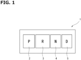
- FIG. 1 is an illustrative view schematically showing a shift operation device 1 of a vehicle to which the present invention is applied.
- Shift operation device 1 includes an input part (switch) of a push-button switch, a touch panel or the like, and is one in which a driver operates (pushes, touches) the input part with, for example, a finger to select a shift position (shift range).
- Shift operation device 1 corresponds to a shift operation part, and is provided with the same number of push-button switches corresponding to shift positions one to one as that of selectable shift positions.
- shift operation device 1 includes a P range button (P button) 2, an R range button (R button) 3, an N range button (N button) 4 and a D range button (D button) 5 as push-button switches.
- P range button 2 corresponds to a parking position in which the power of a drive source is not transmitted to a drive wheel and is operated (pushed) to select the parking position.
- R range button 3 corresponds to a reverse position for moving backward in which the power of the drive source is transmitted to the drive wheel and is operated (pushed) to select the reverse position.
- N range button 4 corresponds to a neutral position in which the power of the drive source is not transmitted to the drive wheel and is operated (pushed) to select the neutral position.
- D range button 5 corresponds to a drive position for moving forward in which the power of the drive source is transmitted to the drive wheel and is operated (pushed) to select the drive position.
- the order of the push buttons in shift operation device 1 is not limited to the order shown in FIG. 1 (in the order of P, R, N and D from the right side in FIG. 1 ) and can be appropriately changed.
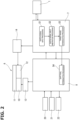
- FIG. 2 is an illustrative view schematically showing a system configuration of the vehicle to which the present invention is applied.
- the vehicle to which the present invention is applied is a hybrid vehicle.
- the vehicle includes, in addition to shift operation device 1, a driving unit 6, a shift controller 7 and a vehicle controller 8.
- Driving unit 6 includes a motor 10 for traveling as a drive source for driving a drive wheel of the vehicle, a speed reduction device 11 for decelerating the rotation of traveling motor 10, and a parking lock mechanism 12 for mechanically locking the rotation of speed reduction device 11.
- traveling motor 10 is a direct drive source of the vehicle, and alternating current is supplied thereto, for example, from a battery (not shown) via an inverter 13.
- traveling motor 10 is a synchronous motor using a permanent magnet to a rotor.
- traveling motor 10 functions as a generator at the time of the deceleration of the vehicle. That is, traveling motor 10 is a generator motor capable of charging regenerative energy to the battery, as electric power, which is generated at the time of the deceleration of the vehicle.
- Speed reduction device 11 is one for ensuring traveling drive torque by decelerating the rotation of traveling motor 10 by the meshing of a plurality of gears so as to increase motor torque.
- Parking lock mechanism 12 switches between a parking lock state in which the rotation of a gear inside speed reduction device 11 is locked and a parking lock release state in which the rotation of a gear inside speed reduction device 11 is allowed.
- Parking lock mechanism 12 is configured to switch between the parking lock state and the parking lock release state by the mechanical action in which a parking lock actuator is operated.
- the mechanical action is one to prevent the gear from rotating when a claw-shaped member is caught in the gear of speed reduction device 11 by performing the advancing and retreating of the claw-shaped member.
- shift controller 7 An operation result of shift operation device 1 is input to shift controller 7. For example, in the push-button switch of the embodiment, when it is operated (pushed), a signal indicating the corresponding shift position is output, and when the operation is released (pushed state is returned to the original state), the output is stopped.
- Engine controller 7 performs, based on the input from shift operation device 1, a switch signal input processing S1, a switch signal input arbitration processing S2 and a target range determination processing S3 in order, and then selects a shift position.
- shift controller 7 When a plurality of switches of shift operation device 1 are pushed so as to overlap each other, shift controller 7 gives the highest priority to the operation of P range button 2, and then gives priority to the operation of N range button 4.
- the priority of the operation of the switch for the shift position in which the power is transmitted to a drive wheel is lower than that of the operation of the switch for the shift position in which the power is not transmitted to a drive wheel.
- switch signal input processing S1 the signal from the switch operated in shift operation device 1 is processed.
- switch signal input processing S1 a fault signal of shift operation device 1 is also processed.
- switch signal input arbitration processing S2 it is determined which push-button switch of shift operation device 1 is operated with respect to the input from shift operation device 1. Specifically, it is determined which switch is operated when, for example, a plurality of switches of shift operation device 1 are pushed to overlap each other.
- target range determination processing S3 it is determined which shift position (shift range) to actually switch to.
- the determination result in target range determination processing S3 is sent to vehicle controller 8.
- Vehicle controller 8 performs a shift final determination processing S4 from the determination result of target range determination processing S3.
- shift final determination processing S4 it is determined whether or not the determination result of target range determination processing S3 is acceptable on the vehicle side. For example, when the vehicle is in a state in which the determination result of target range determination processing S3 is not acceptable, the determination result of target range determination processing S3 is not accepted, and the present shift position is maintained. In addition, the result of shift final determination processing S4 is fed back to shift controller 7.
- shift controller 7 and vehicle controller 8 correspond to a control section, and are configured to determine which shift position is selected from the operation result of shift operation device 1 and control the vehicle based on the shift position which has been determined to be selected.
- shift controller 7 when a fault signal of shift operation device 1 is input to switch signal input processing S1, shift controller 7 does not perform the determination which button corresponding to which range in shift operation device 1 is pushed.
- Shift controller 7 supplies a predetermined electric power to a parking lock actuator 14 such that parking lock actuator 14 can obtain a desired drive output, when the shift position is switched to P range based on the result of shift final determination processing S4 which has been fed back.
- Parking lock actuator 14 is one for operating parking lock mechanism 12.
- Vehicle controller 8 inputs the result of shift final determination processing S4 to inverter 13. That is, as information, which vehicle shift position out of a parking position, a neutral position, a drive position and a reverse position has been selected is input to inverter 13.
- Inverter 13 determines electric power to be supplied to traveling motor 10 based on the command from vehicle controller 8.
- Charging/discharging information of a battery which is capable of supplying electric power to traveling motor 10 is input to vehicle controller 8 from a battery controller 20 which manages the charging/discharging of the battery.
- Control information of an internal combustion engine driven for generating electric power to be supplied to traveling motor 10 is input to vehicle controller 8 from an engine control unit 21 for controlling the internal combustion engine.
- the internal combustion engine is one for driving a generator which generates electric power to be supplied to the battery and the internal combustion engine.
- vehicle controller 8 outputs the information of a shift position to a meter 22 for displaying the shift position.
- FIGS. 3 and 4 each are a flow chart showing a processing flow to determine a shift position which is performed in switch signal input arbitration processing S2 of shift controller 7.
- step S11 the presence of the button input of shift operation device 1 is determined. That is, in step S11, it is determined whether or not any one of the buttons of shift operation device 1 is operated (pushed). When it is determined that there is button input in step S11, the step proceeds to a step S12. When it is determined that there is no button input in step S11, the step proceeds to a step S31.
- step S12 it is determined whether or not a plurality of buttons of shift operation device 1 are simultaneously pushed. That is, in step S12, it is determined whether or not a plurality of buttons of shift operation device 1 are operated so as to overlap each other. When it is determined that the plurality of the buttons are simultaneously pushed in step S12, the step proceeds to a step S13. When it is determined that the plurality of the buttons are not simultaneously pushed in step S12, the step proceeds to a step S17.
- step S13 it is determined whether or not P range button 2 is included in the plurality of the buttons which have been operated. When it is determined that P range button 2 is included in step S13, the step proceeds to a step S14. When it is determined that P range button 2 is not included in step S13, the step proceeds to a step S15.
- step S14 it is determined that the parking position is selected as a shift position, and then the routine this time is ended.
- step S15 it is determined whether or not the previous switch input is performed by P range button 2. That is, in step S15, it is determined whether or not the shift position which has been determined last time is the parking position. When, it is determined that the shift position which has been determined last time is the parking position in step S15, the step proceeds to step S14. When, it is determined that the shift position which has been determined last time is not the parking position in step S15, the step proceeds to a step S16.
- step S16 it is determined that the neutral position is selected as a shift position, and then the routine this time is ended.
- step S17 it is determined whether or not the button input is performed by P range button 2.
- the step proceeds to a step S18.
- the step proceeds to a step S19.
- step S18 it is determined that the parking position is selected as a shift position, and then the routine this time is ended.
- step S19 it is determined whether or not the button input is performed by N range button 4.
- the step proceeds to a step S20.
- the step proceeds to a step S22.
- step S20 it is determined whether or not the previous switch input is performed by P range button 2. That is, in step S20, it is determined whether or not the shift position which has been determined last time is the parking position. When, it is determined that the shift position which has been determined last time is the parking position in step S20, the step proceeds to step S18. When, it is determined that the shift position which has been determined last time is not the parking position in step S20, the step proceeds to a step S21.
- step S21 it is determined that the neutral position is selected as a shift position, and then the routine this time is ended.
- step S22 it is determined whether or not the previous switch input is one including P range button 2 or N range button 4. That is, in step S22, it is determined whether the shift position which has been determined last time is the parking position or the neutral position. When it is determined that the shift position which has been determined last time is the parking position or the neutral position in step S22, the step proceeds to a step S23. When it is determined that the shift position which has been determined last time is not the parking position or the neutral position in step S22, the step proceeds to a step S24.
- the previous switch input in step S22 includes a switch input corresponding to a shift position determined when a plurality of buttons of shift operation device 1 are simultaneously pushed. That is, when the previous shift position is a shift position which has been determined based on the result of the simultaneous pushing of the plurality of the buttons in shift operation device 1, the previous switch input in step S22 becomes one corresponding to the determined shift position.
- step S23 the previous value is held, and the routine this time is ended. That is, in step S23, the shift position selected last time is maintained, and the routine this time is ended.
- step S24 it is determined whether or not the button input is performed by D range button 5.
- the step proceeds to a step S25.
- the step proceeds to a step S28.
- step S25 it is determined whether the previous switch input is no operation. That is, in step S25, it is determined whether or not the previous determination result is no operation. When it is determined that the previous determination is no operation in step S25, the step proceeds to a step S26. When it is determined that the previous determination is not no operation in step S25, the step proceeds to a step S27. In addition, as an example of a case to proceed to step S27, when the finishing (off) of the operation of R range button 3 and the operation (on) of D range button 5 are simultaneously performed, the step proceeds to step S27.
- step S26 it is determined that the drive position is selected as a shift position, and then the routine this time is ended.
- step S27 indefinite input is determined, and the routine this time is ended.
- step S28 it is determined whether or not the previous switch input is no operation. That is, in step S28, it is determined whether or not the previous determination result is no operation. When, it is determined that the previous determination is no operation in step S28, the step proceeds to a step S29. When it is determined that the previous determination is not no operation in step S28, the step proceeds to a step S30. In addition, as an example of a case to proceed to step S30, when the finishing (off) of the operation of D range button 5 and the operation (on) of R range button 3 are simultaneously performed, the step proceeds to step S30.
- step S29 it is determined that the reverse position is selected as a shift position, and then the routine this time is ended.
- step S30 indefinite input is determined, and then the routine this time is ended.
- step S31 no operation is determined, and the routine this time is ended. That is, in step S31, it is determined that any buttons of shift operation device 1 have not been operated.
- FIG. 5 is a timing chart showing the relation between button operation of shift operation device 1 and a shift position (determined range) selected by the determination in switch signal input arbitration processing S2.
- a time t1 is a timing at which D range button 5 is operated (pushed) and is turned on.
- Shift controller 7 determines that D range button 5 is operated at time t1 (steps S11 ⁇ S12 ⁇ S17 ⁇ S19 ⁇ S22 ⁇ S24 ⁇ S25 ⁇ S26 of the flow chart in FIGS. 3 and 4 ). Consequently, the determined range is the drive position from time t1.
- a time t2 is a timing at which R range button 3 is operated (pushed) and turned on in a state in which D range button 5 has been turned on. At this time, D range button 5 is maintained into an on-state. Consequently, shift controller 7 determines that a shift position is changed to a neutral position at time t2 (steps S11 ⁇ S12 ⁇ S13 ⁇ S15 ⁇ S16 of the flow chart in FIG. 3 ). Therefore, the determined range is the neutral position from time t2.
- a time t3 is a timing at which the operation of R range button 3 and the operation of D range button 5 are finished (turned off).
- Shift controller 7 determines that there is no button input of shift operation device 1 at time t3 (steps S11 ⁇ S31 of flow chart in FIGS. 3 and 4 ). Consequently, the determined range is a home position from time t3.
- Shift controller 7 sets the determined range to the home position (Home) in a state (off state) in which all of the buttons of shift operation device 1 are not operated.
- the home position is a state in which shift positions such as the parking position, the neutral position, the drive position and the reverse position are not selected.
- shift controller 7 when the determined range experiences the home position, it can be switched to a new determined range.
- the occurrence of a situation in which the driver wants to drive a vehicle so as to move forward but the vehicle moves backward or the driver wants to drive a vehicle so as to move backward but the vehicle moves forward can be surely suppressed. That is, since the power is not transmitted to a drive wheel when switch operations of shift operation device 1 that cause contradictory behaviors overlap, it is possible to reliably suppress the vehicle from moving in a direction contrary to the intention of the driver.
- a parking position is selected when a shift position determined in switch signal input arbitration processing S2 immediately before these button operations are performed is a parking position that is a shift position in which the power of a drive source is not transmitted to a drive wheel.
- R range button 3 and D range button 5 are operated and the parking position is selected, following which when the operation of P range button 2 is released and switched to a state in which R range button 3 and D range button 5 are operated, the parking position is maintained.
- the present invention can also be applied to a vehicle in which a drive wheel is driven by an internal combustion engine.
- driving unit 6 is composed of an internal combustion engine, a transmission and the like, and a transmission control unit performs processing from switch signal input processing S1 to shift final determination processing S4, and inverter 13 is omitted.
- shift controller 7 and vehicle controller 8 may be configured by one controller.
- shift operation device 1 may perform processing of switch signal input arbitration processing S2.
- the embodiment mentioned above relates to a control method for a vehicle and a control device for the vehicle.
Landscapes
- Engineering & Computer Science (AREA)
- General Engineering & Computer Science (AREA)
- Mechanical Engineering (AREA)
- Control Of Transmission Device (AREA)
- Arrangement Or Mounting Of Control Devices For Change-Speed Gearing (AREA)
Applications Claiming Priority (1)
| Application Number | Priority Date | Filing Date | Title |
|---|---|---|---|
| PCT/JP2022/017285 WO2023195135A1 (ja) | 2022-04-07 | 2022-04-07 | 車両の制御方法及び車両の制御装置 |
Publications (1)
| Publication Number | Publication Date |
|---|---|
| EP4506595A1 true EP4506595A1 (en) | 2025-02-12 |
Family
ID=88242787
Family Applications (1)
| Application Number | Title | Priority Date | Filing Date |
|---|---|---|---|
| EP22936533.3A Withdrawn EP4506595A1 (en) | 2022-04-07 | 2022-04-07 | Control method for vehicle and control device for vehicle |
Country Status (5)
| Country | Link |
|---|---|
| EP (1) | EP4506595A1 (https=) |
| JP (1) | JP7806889B2 (https=) |
| CN (1) | CN119072595A (https=) |
| MX (1) | MX2024012137A (https=) |
| WO (1) | WO2023195135A1 (https=) |
Family Cites Families (12)
| Publication number | Priority date | Publication date | Assignee | Title |
|---|---|---|---|---|
| JPS60167843U (ja) | 1984-04-17 | 1985-11-07 | 三菱自動車工業株式会社 | 押ボタン式自動変速機における複数押ボタンチエツク装置 |
| JPH0217265A (ja) * | 1988-07-05 | 1990-01-22 | Iseki & Co Ltd | 押ボタン型電子変速機の制御装置 |
| JPH0882363A (ja) * | 1995-09-11 | 1996-03-26 | Iseki & Co Ltd | 作業用車両の変速操作装置 |
| JPH08253047A (ja) * | 1995-09-13 | 1996-10-01 | Iseki & Co Ltd | 作業用車両の変速装置 |
| JP2004324849A (ja) * | 2003-04-28 | 2004-11-18 | Nissan Motor Co Ltd | シフトバイワイヤ式自動変速機のレンジ切り換え制御装置 |
| ITMI20052447A1 (it) * | 2005-12-22 | 2007-06-23 | Iveco Spa | Metodo e dispositivo di comando cambio automatizzato per una trasmissione di un veicolo industriale o commerciale |
| JP4853338B2 (ja) * | 2007-03-09 | 2012-01-11 | スズキ株式会社 | シフト操作入力装置 |
| JP4837754B2 (ja) * | 2009-02-17 | 2011-12-14 | ジヤトコ株式会社 | シフトバイワイヤ式車両の制御装置 |
| JP2011207296A (ja) * | 2010-03-29 | 2011-10-20 | Aisin Aw Co Ltd | ハイブリッド駆動装置 |
| JP6093521B2 (ja) * | 2012-08-06 | 2017-03-08 | 株式会社東海理化電機製作所 | シフト装置 |
| JP6060962B2 (ja) | 2014-12-17 | 2017-01-18 | マツダ株式会社 | 車両用シフト装置 |
| US10336186B2 (en) * | 2016-03-23 | 2019-07-02 | Ford Global Technologies, Llc | Pushbutton vehicle shifter interface |
-
2022
- 2022-04-07 CN CN202280093992.XA patent/CN119072595A/zh active Pending
- 2022-04-07 WO PCT/JP2022/017285 patent/WO2023195135A1/ja not_active Ceased
- 2022-04-07 JP JP2024513648A patent/JP7806889B2/ja active Active
- 2022-04-07 EP EP22936533.3A patent/EP4506595A1/en not_active Withdrawn
-
2024
- 2024-09-30 MX MX2024012137A patent/MX2024012137A/es unknown
Also Published As
| Publication number | Publication date |
|---|---|
| JP7806889B2 (ja) | 2026-01-27 |
| CN119072595A (zh) | 2024-12-03 |
| JPWO2023195135A1 (https=) | 2023-10-12 |
| MX2024012137A (es) | 2024-11-08 |
| WO2023195135A1 (ja) | 2023-10-12 |
Similar Documents
| Publication | Publication Date | Title |
|---|---|---|
| US8784246B2 (en) | Series drivetrain with CVT output | |
| EP2949529A1 (en) | Controller of hybrid vehicle | |
| EP3259147B1 (en) | Hybrid vehicle | |
| EP2982559A1 (en) | Vehicle control device | |
| WO2010079606A1 (ja) | 車両の制御装置 | |
| JP5767157B2 (ja) | 車両および車両の制御方法 | |
| EP2821306B1 (en) | Control device for hybrid vehicle | |
| JP2005229765A (ja) | 後退抑制装置 | |
| EP2826654A1 (en) | Generation control apparatus for hybrid vehicle | |
| JP5811262B2 (ja) | ハイブリッド車両の発進制御装置 | |
| EP4506595A1 (en) | Control method for vehicle and control device for vehicle | |
| JP2009222102A (ja) | 車両の制御装置 | |
| EP4506592A1 (en) | Control method for vehicle and control device for vehicle | |
| EP4506199A1 (en) | Control method for vehicle and control device for vehicle | |
| EP4506593A1 (en) | Vehicle control method and vehicle control device | |
| EP2930040A1 (en) | Drive device for hybrid vehicle | |
| EP1698504B1 (en) | Hybrid vehicle and control method thereof | |
| CN113352871A (zh) | 混合动力车辆的驱动装置 | |
| JP2009143361A (ja) | ハイブリッド車両の駆動装置 | |
| JP6583057B2 (ja) | 車両の制御装置 | |
| RU25468U1 (ru) | Система управления трансмисией транспортного средства | |
| US12384236B2 (en) | Hybrid vehicle control apparatus | |
| JP2017081242A (ja) | 車両の制御装置 | |
| JP2022138057A (ja) | ハイブリッド車両の制御装置 | |
| JP2009124898A (ja) | 旋回駆動制御装置及びこれを含む建設機械 |
Legal Events
| Date | Code | Title | Description |
|---|---|---|---|
| STAA | Information on the status of an ep patent application or granted ep patent |
Free format text: STATUS: THE INTERNATIONAL PUBLICATION HAS BEEN MADE |
|
| PUAI | Public reference made under article 153(3) epc to a published international application that has entered the european phase |
Free format text: ORIGINAL CODE: 0009012 |
|
| STAA | Information on the status of an ep patent application or granted ep patent |
Free format text: STATUS: REQUEST FOR EXAMINATION WAS MADE |
|
| 17P | Request for examination filed |
Effective date: 20241014 |
|
| AK | Designated contracting states |
Kind code of ref document: A1 Designated state(s): AL AT BE BG CH CY CZ DE DK EE ES FI FR GB GR HR HU IE IS IT LI LT LU LV MC MK MT NL NO PL PT RO RS SE SI SK SM TR |
|
| STAA | Information on the status of an ep patent application or granted ep patent |
Free format text: STATUS: THE APPLICATION HAS BEEN WITHDRAWN |
|
| 18W | Application withdrawn |
Effective date: 20250403 |