EP4506588A1 - Power transmission pin for speed changer and method of manufacturing power transmission pin for speed changer - Google Patents
Power transmission pin for speed changer and method of manufacturing power transmission pin for speed changer Download PDFInfo
- Publication number
- EP4506588A1 EP4506588A1 EP24191156.9A EP24191156A EP4506588A1 EP 4506588 A1 EP4506588 A1 EP 4506588A1 EP 24191156 A EP24191156 A EP 24191156A EP 4506588 A1 EP4506588 A1 EP 4506588A1
- Authority
- EP
- European Patent Office
- Prior art keywords
- power transmission
- externally threaded
- transmission pin
- shaft portion
- speed
- Prior art date
- Legal status (The legal status is an assumption and is not a legal conclusion. Google has not performed a legal analysis and makes no representation as to the accuracy of the status listed.)
- Pending
Links
Images

Classifications
-
- F—MECHANICAL ENGINEERING; LIGHTING; HEATING; WEAPONS; BLASTING
- F16—ENGINEERING ELEMENTS AND UNITS; GENERAL MEASURES FOR PRODUCING AND MAINTAINING EFFECTIVE FUNCTIONING OF MACHINES OR INSTALLATIONS; THERMAL INSULATION IN GENERAL
- F16H—GEARING
- F16H57/00—General details of gearing
- F16H57/08—General details of gearing of gearings with members having orbital motion
-
- F—MECHANICAL ENGINEERING; LIGHTING; HEATING; WEAPONS; BLASTING
- F16—ENGINEERING ELEMENTS AND UNITS; GENERAL MEASURES FOR PRODUCING AND MAINTAINING EFFECTIVE FUNCTIONING OF MACHINES OR INSTALLATIONS; THERMAL INSULATION IN GENERAL
- F16H—GEARING
- F16H1/00—Toothed gearings for conveying rotary motion
- F16H1/28—Toothed gearings for conveying rotary motion with gears having orbital motion
- F16H1/32—Toothed gearings for conveying rotary motion with gears having orbital motion in which the central axis of the gearing lies inside the periphery of an orbital gear
-
- C—CHEMISTRY; METALLURGY
- C23—COATING METALLIC MATERIAL; COATING MATERIAL WITH METALLIC MATERIAL; CHEMICAL SURFACE TREATMENT; DIFFUSION TREATMENT OF METALLIC MATERIAL; COATING BY VACUUM EVAPORATION, BY SPUTTERING, BY ION IMPLANTATION OR BY CHEMICAL VAPOUR DEPOSITION, IN GENERAL; INHIBITING CORROSION OF METALLIC MATERIAL OR INCRUSTATION IN GENERAL
- C23C—COATING METALLIC MATERIAL; COATING MATERIAL WITH METALLIC MATERIAL; SURFACE TREATMENT OF METALLIC MATERIAL BY DIFFUSION INTO THE SURFACE, BY CHEMICAL CONVERSION OR SUBSTITUTION; COATING BY VACUUM EVAPORATION, BY SPUTTERING, BY ION IMPLANTATION OR BY CHEMICAL VAPOUR DEPOSITION, IN GENERAL
- C23C8/00—Solid state diffusion of only non-metal elements into metallic material surfaces; Chemical surface treatment of metallic material by reaction of the surface with a reactive gas, leaving reaction products of surface material in the coating, e.g. conversion coatings, passivation of metals
- C23C8/06—Solid state diffusion of only non-metal elements into metallic material surfaces; Chemical surface treatment of metallic material by reaction of the surface with a reactive gas, leaving reaction products of surface material in the coating, e.g. conversion coatings, passivation of metals using gases
- C23C8/08—Solid state diffusion of only non-metal elements into metallic material surfaces; Chemical surface treatment of metallic material by reaction of the surface with a reactive gas, leaving reaction products of surface material in the coating, e.g. conversion coatings, passivation of metals using gases only one element being applied
- C23C8/24—Nitriding
-
- C—CHEMISTRY; METALLURGY
- C23—COATING METALLIC MATERIAL; COATING MATERIAL WITH METALLIC MATERIAL; CHEMICAL SURFACE TREATMENT; DIFFUSION TREATMENT OF METALLIC MATERIAL; COATING BY VACUUM EVAPORATION, BY SPUTTERING, BY ION IMPLANTATION OR BY CHEMICAL VAPOUR DEPOSITION, IN GENERAL; INHIBITING CORROSION OF METALLIC MATERIAL OR INCRUSTATION IN GENERAL
- C23C—COATING METALLIC MATERIAL; COATING MATERIAL WITH METALLIC MATERIAL; SURFACE TREATMENT OF METALLIC MATERIAL BY DIFFUSION INTO THE SURFACE, BY CHEMICAL CONVERSION OR SUBSTITUTION; COATING BY VACUUM EVAPORATION, BY SPUTTERING, BY ION IMPLANTATION OR BY CHEMICAL VAPOUR DEPOSITION, IN GENERAL
- C23C8/00—Solid state diffusion of only non-metal elements into metallic material surfaces; Chemical surface treatment of metallic material by reaction of the surface with a reactive gas, leaving reaction products of surface material in the coating, e.g. conversion coatings, passivation of metals
- C23C8/06—Solid state diffusion of only non-metal elements into metallic material surfaces; Chemical surface treatment of metallic material by reaction of the surface with a reactive gas, leaving reaction products of surface material in the coating, e.g. conversion coatings, passivation of metals using gases
- C23C8/08—Solid state diffusion of only non-metal elements into metallic material surfaces; Chemical surface treatment of metallic material by reaction of the surface with a reactive gas, leaving reaction products of surface material in the coating, e.g. conversion coatings, passivation of metals using gases only one element being applied
- C23C8/24—Nitriding
- C23C8/26—Nitriding of ferrous surfaces
-
- C—CHEMISTRY; METALLURGY
- C23—COATING METALLIC MATERIAL; COATING MATERIAL WITH METALLIC MATERIAL; CHEMICAL SURFACE TREATMENT; DIFFUSION TREATMENT OF METALLIC MATERIAL; COATING BY VACUUM EVAPORATION, BY SPUTTERING, BY ION IMPLANTATION OR BY CHEMICAL VAPOUR DEPOSITION, IN GENERAL; INHIBITING CORROSION OF METALLIC MATERIAL OR INCRUSTATION IN GENERAL
- C23C—COATING METALLIC MATERIAL; COATING MATERIAL WITH METALLIC MATERIAL; SURFACE TREATMENT OF METALLIC MATERIAL BY DIFFUSION INTO THE SURFACE, BY CHEMICAL CONVERSION OR SUBSTITUTION; COATING BY VACUUM EVAPORATION, BY SPUTTERING, BY ION IMPLANTATION OR BY CHEMICAL VAPOUR DEPOSITION, IN GENERAL
- C23C8/00—Solid state diffusion of only non-metal elements into metallic material surfaces; Chemical surface treatment of metallic material by reaction of the surface with a reactive gas, leaving reaction products of surface material in the coating, e.g. conversion coatings, passivation of metals
- C23C8/80—After-treatment
-
- F—MECHANICAL ENGINEERING; LIGHTING; HEATING; WEAPONS; BLASTING
- F16—ENGINEERING ELEMENTS AND UNITS; GENERAL MEASURES FOR PRODUCING AND MAINTAINING EFFECTIVE FUNCTIONING OF MACHINES OR INSTALLATIONS; THERMAL INSULATION IN GENERAL
- F16B—DEVICES FOR FASTENING OR SECURING CONSTRUCTIONAL ELEMENTS OR MACHINE PARTS TOGETHER, e.g. NAILS, BOLTS, CIRCLIPS, CLAMPS, CLIPS OR WEDGES; JOINTS OR JOINTING
- F16B19/00—Bolts without screw-thread; Pins, including deformable elements; Rivets
- F16B19/02—Bolts or sleeves for positioning of machine parts, e.g. notched taper pins, fitting pins, sleeves, eccentric positioning rings
-
- F—MECHANICAL ENGINEERING; LIGHTING; HEATING; WEAPONS; BLASTING
- F16—ENGINEERING ELEMENTS AND UNITS; GENERAL MEASURES FOR PRODUCING AND MAINTAINING EFFECTIVE FUNCTIONING OF MACHINES OR INSTALLATIONS; THERMAL INSULATION IN GENERAL
- F16H—GEARING
- F16H57/00—General details of gearing
- F16H57/02—Gearboxes; Mounting gearing therein
-
- F—MECHANICAL ENGINEERING; LIGHTING; HEATING; WEAPONS; BLASTING
- F16—ENGINEERING ELEMENTS AND UNITS; GENERAL MEASURES FOR PRODUCING AND MAINTAINING EFFECTIVE FUNCTIONING OF MACHINES OR INSTALLATIONS; THERMAL INSULATION IN GENERAL
- F16H—GEARING
- F16H57/00—General details of gearing
- F16H57/02—Gearboxes; Mounting gearing therein
- F16H57/023—Mounting or installation of gears or shafts in the gearboxes, e.g. methods or means for assembly
-
- F—MECHANICAL ENGINEERING; LIGHTING; HEATING; WEAPONS; BLASTING
- F16—ENGINEERING ELEMENTS AND UNITS; GENERAL MEASURES FOR PRODUCING AND MAINTAINING EFFECTIVE FUNCTIONING OF MACHINES OR INSTALLATIONS; THERMAL INSULATION IN GENERAL
- F16H—GEARING
- F16H1/00—Toothed gearings for conveying rotary motion
- F16H1/28—Toothed gearings for conveying rotary motion with gears having orbital motion
- F16H1/32—Toothed gearings for conveying rotary motion with gears having orbital motion in which the central axis of the gearing lies inside the periphery of an orbital gear
- F16H2001/325—Toothed gearings for conveying rotary motion with gears having orbital motion in which the central axis of the gearing lies inside the periphery of an orbital gear comprising a carrier with pins guiding at least one orbital gear with circular holes
-
- F—MECHANICAL ENGINEERING; LIGHTING; HEATING; WEAPONS; BLASTING
- F16—ENGINEERING ELEMENTS AND UNITS; GENERAL MEASURES FOR PRODUCING AND MAINTAINING EFFECTIVE FUNCTIONING OF MACHINES OR INSTALLATIONS; THERMAL INSULATION IN GENERAL
- F16H—GEARING
- F16H57/00—General details of gearing
- F16H57/08—General details of gearing of gearings with members having orbital motion
- F16H2057/085—Bearings for orbital gears
Definitions
- the present invention relates to a power transmission pin for a speed changer, a rotating mechanism, a speed changer, and a method of manufacturing a power transmission pin for a speed changer.
- Known rotating mechanisms include speed changers provided with input and output parts. For example, rotation is input from an electric motor or the like into the input part, the input rotation is reduced or increased, and the reduced or increased rotation is output through the output part.
- Known speed changers include eccentric oscillation speed reducers that has high load capacity and high accuracy in rotational position.
- This type of speed reducer includes:, for example, a case (frame) having an internal gear formed on its inner circumferential surface; an oscillating gear (external gear) meshed with the internal gear and configured to oscillatorily rotate; a crankshaft (input rotator) having an eccentric portion rotatably supporting the oscillating gear and being configured to transmit a rotational force to the oscillating gear, a power transmission pin (carrier pin) configured to receive a rotational force transmitted from the oscillating gear, and a carrier (output rotator) connected to the power transmission pin.
- the oscillating gear has a pin insertion hole through which the power transmission pin is inserted.
- the carrier has a pin insertion hole into which the power transmission pin is inserted or pushed. As the power transmission pin is inserted into these pin insertion holes, the rotation of the oscillating gear can be transmitted to the carrier via the power transmission pin.
- the pin insertion hole of the oscillating gear is sized such that it can allow the oscillating gear to oscillate relative to the power transmission pin.
- the pin insertion hole of the oscillating gear has a cylindrical bushing inserted. The power transmission pin is inserted through the bushing.
- the power transmission pin may slip out of the carrier as it moves in a certain direction.
- the power transmission pin is restricted from moving in this direction by, for example, having an externally threaded portion at its tip and a nut tightened onto the externally threaded portion.
- the externally threaded portion of the power transmission pin protrudes outside in the axial direction through the pin insertion hole of the carrier. As the nut is tightened onto the protruding externally threaded portion, the power transmission pin is restricted from moving relative to the carrier in the direction (see, for example, Patent Literature 1).
- Patent Literature 1 Japanese Patent Application Publication No. 2017-82993
- the power transmission pin plays a role of transmitting the rotational force of the oscillating gear to the carrier. This means that the power transmission pin may be heavily loaded.
- the power transmission pin is thus required to have improved strength and toughness.
- the power transmission pin is also required to have improved wear resistance since it is designed to slide relative to the bushing.
- the power transmission pin is accordingly required to have improved wear resistance in addition to improved strength and toughness.
- conventional power transmission pins have room for improvement.
- An objective of the present invention is to provide a power transmission pin for a speed changer, a rotating mechanism, a speed changer, and a method of manufacturing a power transmission pin for a speed changer that are capable of achieving improved strength, toughness and wear resistance.
- One aspect of the present invention provides a power transmission pin for a speed changer, the power transmission pin being used in a speed changer and configured to transmit power, the speed changer including a speed changing mechanism configured to receive rotation input thereto, change a speed of the rotation, and output the speed-changed rotation.
- the power transmission pin includes a shaft portion, and an externally threaded portion configured to fixedly attach the shaft portion onto the speed changing mechanism, the externally threaded portion being formed on an end of the shaft portion in an axial direction, the externally threaded portion and the shaft portion being coaxially arranged. At least a surface of the shaft portion has higher hardness than the externally threaded portion.
- the anti-wear resistance, strength and toughness of the power transmission pin for a speed changer may be enhanced simply by raising the hardness of the entire power transmission pin for a speed changer. This attempt, however, may result in damaging the externally threaded portion of the power transmission pin for a speed changer. Considering this, the hardness of at least the surface of the shaft portion of the power transmission pin for a speed changer is higher than that of the externally threaded portion. In this way, the externally threaded portion is less likely to be damaged while the shaft portion, which may receive the highest load, can have sufficient strength.
- the power transmission pin can thus achieve improved strength, toughness and anti-wear resistance.
- the surface of the shaft portion may be nitrided into a nitride layer.
- a rotating mechanism including: a rotator having an insertion hole; a tubular bushing in the insertion hole; and a power transmission pin inserted through the bushing.
- the power transmission pin includes: a shaft portion; and an externally threaded portion connecting the rotator and the power transmission pin into a single piece, the externally threaded portion being formed on an end of the shaft portion in an axial direction, the externally threaded portion and the shaft portion being coaxially arranged. At least a surface of the shaft portion has higher hardness than the externally threaded portion and than the bushing.
- the anti-wear resistance of the shaft portion against the bushing can be certainly improved.
- the rotating mechanism can thus achieve improved strength, toughness and anti-wear resistance.
- the surface of the shaft portion may be nitrided into a nitride layer.
- a further aspect of the present invention provides a speed changer including: an input part configured to rotate; a speed changing mechanism configured to change a speed of rotation of the input part; and an output part configured to receive the rotation of the input part transmitted via the speed changing mechanism.
- the speed changing mechanism includes: a gear having a pin insertion hole; a power transmission pin inserted through the pin insertion hole; and a tubular bushing inserted through the pin insertion hole and fitted onto the power transmission pin.
- the power transmission pin includes: a shaft portion; and an externally threaded portion connecting the gear and the power transmission pin into a single piece, the externally threaded portion being formed on an end of the shaft portion in an axial direction, the externally threaded portion and the shaft portion being coaxially arranged. At least a surface of the shaft portion has higher hardness than the externally threaded portion and than the bushing.
- the anti-wear resistance of the shaft portion against the bushing can be certainly improved.
- the speed changer can thus achieve improved strength, toughness and anti-wear resistance.
- the surface of the shaft portion may be nitrided into a nitride layer.
- a yet another aspect of the present invention provides a method of manufacturing a power transmission pin for a speed changer, the power transmission pin being used in a speed changer and configured to transmit power, the speed changer including a speed changing mechanism configured to receive rotation input thereto, change a speed of the input rotation and output the speed-changed rotation.
- the method includes steps of: hardening a surface of a rod-shaped base material; subsequent to the hardening, removing the hardened surface from a portion of an end of the base material in an axial direction; processing, into an externally threaded portion, the portion of the base material from which the hardened surface is removed by the removing.
- the shaft portion and externally threaded portion of the power transmission pin for a speed changer are formed from the single base material, at least the surface of the shaft portion can accomplish higher hardness than the externally threaded portion in a simplified manner.
- the method may further include a step of, prior to the hardening, quenching and tempering the base material.
- a yet another aspect of the present invention provides a method of manufacturing a power transmission pin for a speed changer, the power transmission pin being used in a speed changer and configured to transmit power, the speed changer including a speed changing mechanism configured to receive rotation input thereto, change a speed of the input rotation and output the speed-changed rotation.
- the method includes steps of: processing a portion of an end of a rod-shaped base material in an axial direction into an externally threaded portion; and subsequent to the processing, hardening a surface of the base material excluding the externally threaded portion.
- the shaft portion and externally threaded portion of the power transmission pin for a speed changer are formed from the single base material, at least the surface of the shaft portion can accomplish higher hardness than the externally threaded portion in a simplified manner.
- the hardening may include nitriding the surface of the base material into a nitride layer.
- the above-described power transmission pin for a speed changer, rotating mechanism, speed changer, and method of manufacturing a power transmission pin for a speed changer achieve improved strength, toughness and wear resistance.
- Fig. 1 is a sectional view of a speed reducer 1.
- the speed reducer 1 is an eccentric oscillation speed reducer.
- the speed reducer 1 includes a circular-cylindrical case 2, and a carrier 7 rotatably supported on the case 2 via two bearings 15a and 15b (a first bearing 15a and a second bearing 15b).
- axial direction refers to the axial direction of the case 2.
- circumferential direction refer to the circumferential direction of the case 2.
- radial direction refer to the radial direction of the case 2.
- the case 2 is made of, for example, an iron-based material such as cast iron.
- the case 2 may be made of, for example, an aluminum alloy, a magnesium alloy, carbon fiber reinforced plastic (CFRP), or a resin containing boron nitride for improved thermal conductivity.
- An outer flange portion 4 projecting outward in the radial direction is integrally formed with the outer circumferential surface 2a of the case 2.
- the outer flange portion 4 has a rectangular section when cut along the axial direction.
- the outer flange portion 4 has a plurality of bolt holes 4a penetrating therethrough in the axial direction and arranged at equal intervals in the circumferential direction.
- a device (not shown), to which the speed reducer 1 is attached, is overlaid on the outer flange portion 4.
- Bolts (not shown) are inserted into the bolt holes 4a of the outer flange portion 4 and tightened into the device. In this way, the speed reducer 1 can be secured onto the device.
- the inner circumferential surface 2b of the case 2 has, at the opposite ends in the axial direction, bearing housings 3a and 3b (a first bearing housing 3a and a second bearing housing 3b).
- the bearing housings 3a and 3b have, via a step, a greater inner diameter than the inner circumferential surface 2b of the case 2.
- the first bearing 15a is fitted into the first bearing housing 3a.
- the second bearing 15b is fitted into the second bearing housing 3b.
- the first and second bearings 15a and 15b are, for example, ball bearings.
- the portion of the inner circumferential surface 2b of the case 2 that is positioned on the axially outer side of the second bearing housing 3b forms a seal housing 5.
- the seal housing 5 has, via a step, a greater inner diameter than the second bearing housing 3b.
- the seal housing 5 fittedly receives a seal 40.
- the seal 40 provides sealing between the case 2 and the carrier 7.
- the portion of the inner circumferential surface 2b of the case 2 that is positioned between the two bearing housings 3a and 3b has a plurality of internal tooth pins 6.
- Each of the internal tooth pins 6 is shaped like a circular column extending in the axial direction.
- the present embodiment is, however, not limited to such, and the internal tooth pins 6 may be hollow members.
- the internal tooth pins 6 are arranged at regular intervals in the circumferential direction.
- the internal tooth pins 6 constitute part of a speed reducing mechanism 30. Specifically, the internal tooth pins 6 serve as internal teeth meshing with oscillating gears 11 band 12, which will be described below.
- the speed reducing mechanism 30 includes: the carrier 7; power transmission pins 9 provided in the carrier 7; a crankshaft 8 rotatably supported by the carrier 7 via two bearings 15c and 15d (a third bearing 15c and a fourth bearing 15d); and two oscillating gears 11 and 12 (a first oscillating gear 11 and a second oscillating gear 12) rotatably supported by the crankshaft 8.
- the axis of rotation of the carrier 7 coincides with the axis of rotation of the crankshaft 8. These axes of rotation coincide with the central axis of the case 2.
- the carrier 7 is constituted by a first flange 13 and a second flange 14 facing each other in the axial direction and shaped like a disk.
- the first and second flanges 13 and 14 are made of, for example, an iron-based material such as cast iron.
- the first flange 13 has a first opening 13a extending through the first flange 13 in the axial direction.
- the first opening 13a occupies a large part of the radially central portion of the first flange 13.
- the portion of the outer circumferential surface of the first flange 13 that faces the second flange 14 constitutes a first diameter-reduced portion 13b.
- the first diameter-reduced portion 13b has, via a step, a smaller outer diameter than the first flange 13.
- the first bearing 15a is fitted onto the first diameter-reduced portion 13b.
- the portion of the inner circumferential surface of the first opening 13a that faces the second flange 14 constitutes a first diameter-increased portion 13c.
- the first diameter-increased portion 13c has, via a step, a greater inner diameter than the first opening 13a.
- the third bearing 15c is fitted onto the first diameter-increased portion 13c.
- the third bearing 15c is, for example, a ball bearing.
- the first flange 13 has a plurality of first bolt insertion holes 51.
- the first bolt insertion holes 51 are arranged at equal intervals in the circumferential direction.
- Each of the first bolt insertion holes 51 is divided into a shaft insertion portion 51a facing the second flange 14, and a threaded insertion portion 51b facing away from the second flange 14.
- the shaft insertion portion 51a and threaded insertion portion 51b are coaxially arranged.
- the shaft insertion portion 51a and threaded insertion portion 51b are in communication with each other.
- the threaded insertion portion 51b has, via a step 51c, a smaller inner diameter than the shaft insertion portion 51a.
- the outer circumferential surface of the second flange 14 has a portion that faces the seal housing 5 of the case 2 in the radial direction.
- a seal 40 is fitted onto this portion of the outer circumferential surface of the second flange 14. This can provide sealing between the case 2 and the second flange 14 that constitutes a part of the carrier 7.
- the second flange 14 has a second opening 14a extending through the second flange 14 in the axial direction.
- the second opening 14a occupies a large part of the radially central portion of the second flange 14.
- the portion of the outer circumferential surface of the second flange 14 that faces the first flange 13 constitutes a second diameter-reduced portion 14b.
- the second diameter-reduced portion 14b has, via a step, a smaller outer diameter than the second flange 14.
- the second bearing 15b is fitted onto the second diameter-reduced portion 14b.
- the portion of the inner circumferential surface of the second opening 14a that faces the first flange 13 constitutes a second diameter-increased portion 14c.
- the second diameter-increased portion 14c has, via a step, a greater inner diameter than the second opening 14a.
- the fourth bearing 15d is fitted onto the second diameter-increased portion 14c.
- the fourth bearing 15d is, for example, a ball bearing.
- the second flange 14 has a plurality of second bolt insertion holes 52.
- the second bolt insertion holes 52 are arranged at equal intervals in the circumferential direction.
- the first and second bolt insertion holes 51 and 52 are coaxially arranged.
- the inner diameter of the second bolt insertion holes 52 is equal to that of the shaft insertion portions 51a of the first bolt insertion holes 51.
- Each of the second bolt insertion holes 52 has a counterboring portion 52a on the side facing away from the first flange 13.
- the counterboring portion 52a has, via a step 52b, a greater inner diameter than the second bolt insertion hole 52.
- the power transmission pins 9 are respectively inserted through the bolt insertion holes 51 and 52 of the flanges 13 and 14.
- the power transmission pins 9 are formed of, for example, aluminum chromium molybdenum steels.
- Each of the power transmission pins 9 includes: a shaft portion 61 shaped like a circular column; an externally threaded portion 62 integrally formed at one end of the shaft portion 61 in the axial direction; and a head 63 integrally formed at the other end of the shaft portion 61 in the axial direction.
- the shaft portion 61, externally threaded portion 62 and head 63 are coaxially arranged.
- the outer diameter of the shaft portion 61 is equal to or slightly less than the inner diameter of the shaft insertion portion 51a of the first bolt insertion hole 51, or the inner diameter of the second bolt insertion hole 52.
- the externally threaded portion 62 has, via a step 62a, a smaller outer diameter than the shaft portion 61.
- the base of the externally threaded portion 62, which faces the shaft portion 61, has a semi-threaded portion 62b.
- the head 63 has, via a step 63a, a greater outer diameter than the shaft portion 61.
- the outer diameter of the head 63 is slightly smaller than the outer diameter of the counterboring portion 52a of the second flange 14.
- the above-described power transmission pins 9 are inserted from the second flange 14 side with the externally threaded portions 62 pointing toward the first flange 13, first through the second bolt insertion holes 52 and then through the first bolt insertion holes 51.
- the heads 63 of the power transmission pins 9 are inserted into the counterboring portions 52a of the second bolt insertion holes 52. Since the steps 63a of the power transmission pins 9 butt up against the steps 52b of the second bolt insertion holes 52, the power transmission pins 9 can be rightly positioned in the axial direction with respect to the second flange 14.
- the externally threaded portions 62 of the power transmission pins 9 protrude outside beyond the first bolt insertion holes 51 in the axial direction.
- the semi-threaded portions 62b of the externally threaded portions 62 are inserted into the threaded insertion portions 51b of the first bolt insertion holes 51.
- the ends of the shaft portions 61 that face the externally threaded portions 62 are inserted into the shaft insertion portions 51a of the first bolt insertion holes 51. Since the steps 62a of the power transmission pins 9 butt up against the steps 51c of the first bolt insertion holes 51, the power transmission pins 9 can be rightly positioned in the axial direction with respect to the first flange 13.
- the power transmission pins 9 are secured into the carrier 7 (first and second flanges 13 and 14). How to manufacture the power transmission pins 9 will be described below in detail.
- two bushings 67a and 67b (a first bushing 67a and a second bushing 67b) are fitted onto the shaft portion 61 of each power transmission pin 9 between the first and second flanges 13 and 14.
- the bushings 67a and 67b are made of, for example, high carbon chromium bearing steels such as SUJ2.
- crankshaft 8 While being inserted through the first and second openings 13a and 14a, the crankshaft 8 is rotatably supported by the flanges 13 and 14 via the third and fourth bearings 15c and 15d.
- the crankshaft 8 is made of, for example, an aluminum alloy.
- the crankshaft 8 may be made of other possible source materials such as stainless steels or various ferrous metals.
- the crankshaft 8 is hollow.
- the inner circumferential surface of the crankshaft 8 has a key groove 66.
- the key groove 66 is used to couple the crankshaft 8 with a motor shaft of an electric motor that may be provided on a device, which is not shown.
- the crankshaft 8 has a first eccentric portion 21a and a second eccentric portion 21b arranged in the axial direction between the third and fourth bearings 15c and 15d.
- the first eccentric portion 21a is closer to the first flange 13.
- the second eccentric portion 21b is closer to the second flange 14.
- the axes of the eccentric portions 21a and 21b are shifted from the axis of rotation of the crankshaft 8 (carrier 7).
- the eccentric portions 21a and 21b are out of phase with each other.
- the eccentric portions 21a and 21b are out of phase with each other by 180°.
- the eccentric portions 21a and 21b are respectively provided with bearings 15e and 15f (a fifth bearing 15e and a sixth bearing 15f).
- the fifth and sixth bearings 15e and 15f are, for example, needle bearings.
- the eccentric portions 21a and 21b rotatably support the oscillating gears 11 and 12 (first oscillating gear 11 and second oscillating gear 12) via the bearings 15e and 15f, respectively.
- the oscillating gears 11 and 12 are disposed between the first and second flanges 13 and 14.
- the two oscillating gears 11 and 12 are made of, for example, an iron-based material such as chrome molybdenum steel.
- the two oscillating gears 11 and 12 respectively have crankshaft insertion holes 24a and 24b (a first crankshaft insertion hole 24a, a second crankshaft insertion hole 24b) at their center in the radial direction.
- the crankshaft insertion holes 24a and 24b extend through the oscillating gears 11 and 12 in the thickness direction.
- the crankshaft insertion holes 24a and 24b fittingly receive the bearings 15e and 15f, respectively.
- External teeth 23a and 23b that mesh with the internal tooth pins 6 provided on the case 2 are formed on the outer peripheral portions of the two oscillating gears 11 and 12, respectively.
- the number of external teeth 23a and 23b is smaller than that of the internal tooth pins 6 by, for example, one.
- the two oscillating gears 11 and 12 have pin insertion holes 25a and 25b (first pin insertion holes 25a and second pin insertion holes 25b) that are aligned with the power transmission pins 9.
- the shaft portions 61 of the power transmission pins 9 pass through the pin insertion holes 25a and 25b.
- the first bushings 67a fitted on the shaft portions 61 pass through the first pin insertion holes 25a.
- the second bushings 67b fitted on the shaft portions 61 pass through the second pin insertion holes 25b.
- the eccentric portions 21a and 21b of the crankshaft 8 can cause the oscillating gears 11 and 12 to oscillatorily rotate.
- the inner diameters of the pin insertion holes 25a and 25b of the oscillating gears 11 and 12 are large enough to allow the oscillatory rotation of the oscillating gears 11 and 12 with the shaft portions 61 of the power transmission pins 9 and bushings 67a and 67b being inserted in the pin insertion holes 25a and 25b.
- the oscillating gears 11 and 12 rotatably supported by the eccentric portions 21a and 21b may oscillatorily rotate. This causes some of the external teeth 23a and 23b of the oscillating gears 11 and 12 to mesh with the internal tooth pins 6 of the case 2. Since the number of external teeth 23a and 23b is less than that of the internal tooth pins 6 by, for example, one, the meshing positions of the external teeth 23a and 23b with the internal tooth pins 6 (case 2) move sequentially in the circumferential direction while the oscillating gears 11 and 12 rotate on their own axis. The rotation of the oscillating gears 11 and 12 on their own axis is at a lower speed than the rotation of the crankshaft 8.
- the power transmission pins 9 pass through the pin insertion holes 25a and 25b of the oscillating gears 11 and 12. Upon rotation of the oscillating gears 11 and 12 on their own axis, the rotational force produced by the oscillating gears 11 and 12 in the rotational direction is transmitted to the power transmission pins 9 via the bushings 67a and 67b.
- the power transmission pins 9 are fixedly attached onto the carrier 7 (first and second flanges 13 and 14). Thus, the rotational force produced by the oscillating gears 11 and 12 is transmitted to the carrier 7.
- the carrier 7 is rotatably supported by the case 2 via the first and second bearings 15a and 15b.
- the carrier 7 can rotate relative to the case 2. Therefore, the rotation is input into the crankshaft 8, reduced and then output through the carrier 7.
- the power transmission pins 9 are highly loaded because they are configured to transmit to the carrier 7 the rotation of the oscillating gears 11 and 12, which results from reducing the rotation of the crankshaft 8.
- the power transmission pins 9 are thus manufactured in the following manner.
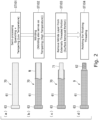
- Fig. 2 shows the steps (a) to (d) of the method of manufacturing each of the power transmission pins 9.
- the views (a) to (c) of Fig. 2 are side views of a base material 70 of the power transmission pin 9.
- the views (b) and (c) of Fig. 2 are cutaway drawings showing the base material 70.
- the base material 70 of the power transmission pin 9 is quenched and tempered (step ST101: semi-processing step).
- step ST101 semi-processing step.
- a portion of the base material 70 that is to be processed into the externally threaded portion 62 of the power transmission pin 9 has not been processed yet and thus has the same diameter as the shaft portion 61.
- the base material 70 has, on the other hand, the head 63 of the power transmission pin 9.
- the base material 70 is not thermally processed yet.
- the quenching is performed at the temperature of 860°C and for the duration of approximately one hour, for example.
- the tempering is performed at a relatively low temperature. Specifically, the tempering is performed at the temperature of 160°C and for the duration of approximately two hours, for example.
- the quenching and tempering can lead to improved toughness (capability to withstand stress and strain)of the base material 70.
- the base material 70 has approximately Rockwell hardness [HRC] of 37 to 45, for example.
- the surface of the base material 70 is hardened (step ST102: surface hardening step). Specifically, the surface of the base material 70 is nitrided to form a nitride layer N.
- the nitriding step is performed at the temperature of 520°C and for the duration of approximately thirty-five hours, for example.
- the nitride layer N has a thickness of approximately 0.2 mm, for example.
- the nitride layer N has Vickers hardness [HV] of approximately 1000 to 750, for example.
- the surface of the base material 70 namely, the nitride layer N has hardness at a different level than the internal portion (core portion) of the base material 70.
- the above-mentioned level of hardness of the nitride layer N is higher than the level of hardness of the bushings 67a and 67b.
- a surface removed portion 71 refers to the portion in which the nitride layer N has been removed. Since the nitride layer N has been removed from the surface of the surface removed portion 71, the surface of the surface removed portion 71 has Rockwell hardness [HRC] of approximately 37 to 45, for example. For the removing performed to form the surface removed portion 71, the amount of removing is set at approximately 0.5 mm, for example. Since the nitride layer N has a thickness of approximately 0.2 mm, the surface removing step can sufficiently remove the nitride layer N.
- the amount of removing for the surface removing step may be set such that the step can not entirely remove the nitride layer N.
- the amount of removing may be set to approximately 0.1 mm. In this case, it is only the nitride layer N that can be removed. This may make the surface removing step difficult as it is only the high hardness layer that can be removed.
- the surface removing step can be made easy since the amount of removing for the surface removing step is large enough to remove not only the nitride layer N but also a slight portion of the internal layer.
- the surface removed portion 71 is processed into the externally threaded portion 62 (step ST104: threading step).
- the shaft portion 61 is polished for finishing.
- the manufacturing of the power transmission pin 9 is completed.
- the surface removed portion 71 is processed into the externally threaded portion 62.
- the shaft portion 61 has the nitride layer N as the surface. This means that the hardness of the surface of the shaft portion 61 is higher than that of the externally threaded portion 62. Furthermore, the hardness of the surface of the shaft portion 61 is higher than that of the bushings 67a and 67b.
- the hardness of the surface of the shaft portion 61 is higher than that of the externally threaded portion 62.
- the power transmission pin 9 can thus achieve improved strength, toughness and anti-wear resistance.
- the anti-wear resistance, strength and toughness of the power transmission pin 9 may be enhanced simply by raising the hardness of the entire power transmission pin 9. This attempt, however, may result in damaging the externally threaded portion 62 of the power transmission pin 9.
- the present embodiment proposes the above-described power transmission pin 9, where the hardness of the surface of the shaft portion 61 is higher than that of the externally threaded portion 62.
- the externally threaded portion 62 is less likely to be damaged while the shaft portion 61, which may receive the highest load, can have sufficient strength.
- the externally threaded portion 62 also has improved toughness due to the quenching and tempering.
- the power transmission pin 9 can thus achieve improved strength, toughness and anti-wear resistance.
- the surface of the shaft portion 61 is nitrided to form the nitride layer N.
- the shaft portion 61 can thus reliably have a highly hard surface.
- the hardness of the surface of the shaft portion 61 is higher than that of the bushings 67a and 67b.
- the anti-wear resistance of the shaft portion 61 against the bushings 67a and 67b can be thus certainly improved.
- the speed reducer 1 can thus achieve improved strength, toughness and anti-wear resistance.
- a method of manufacturing the power transmission pin 9 includes: a surface hardening step of hardening the surface of the base material 70, a surface removing step performed subsequently to the surface hardening step; and a threading step of processing the surface removed portion 71 produced by the surface removing step into the externally threaded portion 62. While the shaft portion 61 and externally threaded portion 62 are formed from the single base material 70, the surface of the shaft portion 61 can accomplish a higher hardness than the externally threaded portion 62 in a simplified manner. As an alternative example, after the power transmission pin 90 has the final shape, the nitriding step may be possibly performed while the externally threaded portion 62 of the power transmission pin 9 is prevented from getting nitrided. This is, however, burdensome. In comparison to this alternative method, the above-described manufacturing method can efficiently manufacture the power transmission pin 9.
- the base material 70 is subject to quenching and tempering. This can impart desired strength and toughness to the externally threaded portion 62. Since the base material 70 is quenched and tempered in advance, the subsequent surface hardening step can be completed within a shorter period of time. This is because the surface hardening step is also tempering treatment performed at a high temperature. Since the previously performed quenching and tempering treatment serves as low-temperature tempering treatment, the duration of the surface hardening step can be shortened.
- the base material 70 goes through the surface hardening step, surface removing step and threading step in the stated order in order to allow the surface of the shaft portion 61 to have higher hardness than the externally threaded portion 62.
- the present embodiment is not limited to such.
- the manufacturing method can be modified in any manner as long as the surface of the shaft portion 61 can have higher hardness than the externally threaded portion 62 in the finished product or the power transmission pin 9.
- the surface of the shaft portion 61 can be hardened by forming a diamond like carbon (DLC) coating on the surface of the shaft portion 61 instead of the nitriding treatment.
- the method of manufacturing the power transmission pin 9 starts with a step of processing the base material 70 to have the externally threaded portion 62 (the threading step). After this, the surface of the portion of the base material 70 that excludes the externally threaded portion 62 (the surface of the shaft portion 61) is hardened (the surface hardening step). If the surface of the shaft portion 61 is hardened by forming a DLC coating, the hardening step is performed after masking the externally threaded portion 62.
- This alternative method can also produce the same advantageous effects as the above-described embodiment.
- the power transmission pins 9 are formed of, for example, aluminum chromium molybdenum steels.
- the present embodiment can be modified as long as the hardness of the surface of the shaft portion 61 is higher than that of the externally threaded portion 62.
- the power transmission pins 9 may be formed of any other materials than aluminum chromium molybdenum steels.
- the power transmission pins 9 may be made of steel materials such as chrome molybdenum steels.
- the surface of the shaft portion 61 can achieve higher hardness than the externally threaded portion 62 by performing high-frequency quenching on the surface of the shaft portion 61.
- the manufacturing method is performed in the same manner as in the foregoing case of forming a DLC coating.
- the hardness of the surface of the shaft portion 61 is higher than that of the externally threaded portion 62 in each power transmission pin 9.
- the nitride layer N has hardness at a different level than the internal portion (core portion) in the shaft portion 61.
- the present embodiment can be modified in any manner as long as at least the surface of the shaft portion 61 has higher hardness than the externally threaded portion 62.
- the internal portion of the shaft portion 61 may have hardness of the same level as the surface.
- the above-described embodiment is directed to the speed reducer 1 including the speed reducing mechanism 30 configured to reduce the rotation of the crankshaft 8 and output the reduced rotation.
- the embodiment is, however, not limited to such, and the above-described power transmission pins 9 may be applied to speed increasers in place of the speed reducing mechanism 30.
- the power transmission pins 9 may be applied to rotating mechanisms including rotators instead of the speed reducing mechanism 30 (carrier 7 and oscillating gears 11 and 12).
- the power transmission pins 9 can be applied to any rotating mechanisms as long as their rotators have pin insertion holes (pin insertion holes 25a and 25b) through which the power transmission pins 9 can be inserted.
- a member formed of multiple components may be integrated into a single component, or conversely, a member formed of a single component may be divided into multiple components. As long as it is configured such that the purpose of the invention can be achieved, such components may be integrated or separately provided.
Landscapes
- Engineering & Computer Science (AREA)
- General Engineering & Computer Science (AREA)
- Chemical & Material Sciences (AREA)
- Mechanical Engineering (AREA)
- Chemical Kinetics & Catalysis (AREA)
- Materials Engineering (AREA)
- Metallurgy (AREA)
- Organic Chemistry (AREA)
- Retarders (AREA)
- General Details Of Gearings (AREA)
Abstract
A power transmission pin (9) relating to an embodiment includes a shaft portion (61) and an externally threaded portion (62) configured to fixedly attach the shaft portion (61) onto a speed changing mechanism (30), the externally threaded portion (62) being formed on an end of the shaft portion (61) in an axial direction, the externally threaded portion (62) and the shaft portion (61) being coaxially arranged. At least a surface of the shaft portion (61) has higher hardness than the externally threaded portion (62).
Description
- The present invention relates to a power transmission pin for a speed changer, a rotating mechanism, a speed changer, and a method of manufacturing a power transmission pin for a speed changer.
- Known rotating mechanisms include speed changers provided with input and output parts. For example, rotation is input from an electric motor or the like into the input part, the input rotation is reduced or increased, and the reduced or increased rotation is output through the output part. Known speed changers include eccentric oscillation speed reducers that has high load capacity and high accuracy in rotational position. This type of speed reducer includes:, for example, a case (frame) having an internal gear formed on its inner circumferential surface; an oscillating gear (external gear) meshed with the internal gear and configured to oscillatorily rotate; a crankshaft (input rotator) having an eccentric portion rotatably supporting the oscillating gear and being configured to transmit a rotational force to the oscillating gear, a power transmission pin (carrier pin) configured to receive a rotational force transmitted from the oscillating gear, and a carrier (output rotator) connected to the power transmission pin.
- The oscillating gear has a pin insertion hole through which the power transmission pin is inserted. The carrier has a pin insertion hole into which the power transmission pin is inserted or pushed. As the power transmission pin is inserted into these pin insertion holes, the rotation of the oscillating gear can be transmitted to the carrier via the power transmission pin. The pin insertion hole of the oscillating gear is sized such that it can allow the oscillating gear to oscillate relative to the power transmission pin. The pin insertion hole of the oscillating gear has a cylindrical bushing inserted. The power transmission pin is inserted through the bushing.
- The power transmission pin may slip out of the carrier as it moves in a certain direction. The power transmission pin is restricted from moving in this direction by, for example, having an externally threaded portion at its tip and a nut tightened onto the externally threaded portion. The externally threaded portion of the power transmission pin protrudes outside in the axial direction through the pin insertion hole of the carrier. As the nut is tightened onto the protruding externally threaded portion, the power transmission pin is restricted from moving relative to the carrier in the direction (see, for example, Patent Literature 1).
- Patent Literature 1:
Japanese Patent Application Publication No. 2017-82993 - Referring to the above-described conventional art, the power transmission pin plays a role of transmitting the rotational force of the oscillating gear to the carrier. This means that the power transmission pin may be heavily loaded. The power transmission pin is thus required to have improved strength and toughness. The power transmission pin is also required to have improved wear resistance since it is designed to slide relative to the bushing. The power transmission pin is accordingly required to have improved wear resistance in addition to improved strength and toughness. In this regard, conventional power transmission pins have room for improvement.
- An objective of the present invention is to provide a power transmission pin for a speed changer, a rotating mechanism, a speed changer, and a method of manufacturing a power transmission pin for a speed changer that are capable of achieving improved strength, toughness and wear resistance.
- One aspect of the present invention provides a power transmission pin for a speed changer, the power transmission pin being used in a speed changer and configured to transmit power, the speed changer including a speed changing mechanism configured to receive rotation input thereto, change a speed of the rotation, and output the speed-changed rotation. The power transmission pin includes a shaft portion, and an externally threaded portion configured to fixedly attach the shaft portion onto the speed changing mechanism, the externally threaded portion being formed on an end of the shaft portion in an axial direction, the externally threaded portion and the shaft portion being coaxially arranged. At least a surface of the shaft portion has higher hardness than the externally threaded portion.
- The anti-wear resistance, strength and toughness of the power transmission pin for a speed changer may be enhanced simply by raising the hardness of the entire power transmission pin for a speed changer. This attempt, however, may result in damaging the externally threaded portion of the power transmission pin for a speed changer. Considering this, the hardness of at least the surface of the shaft portion of the power transmission pin for a speed changer is higher than that of the externally threaded portion. In this way, the externally threaded portion is less likely to be damaged while the shaft portion, which may receive the highest load, can have sufficient strength. The power transmission pin can thus achieve improved strength, toughness and anti-wear resistance.
- In the implementation, the surface of the shaft portion may be nitrided into a nitride layer.
- Another aspect of the present invention provides a rotating mechanism including: a rotator having an insertion hole; a tubular bushing in the insertion hole; and a power transmission pin inserted through the bushing. The power transmission pin includes: a shaft portion; and an externally threaded portion connecting the rotator and the power transmission pin into a single piece, the externally threaded portion being formed on an end of the shaft portion in an axial direction, the externally threaded portion and the shaft portion being coaxially arranged. At least a surface of the shaft portion has higher hardness than the externally threaded portion and than the bushing.
- In the rotating mechanism, the anti-wear resistance of the shaft portion against the bushing can be certainly improved. The rotating mechanism can thus achieve improved strength, toughness and anti-wear resistance.
- In the implementation, the surface of the shaft portion may be nitrided into a nitride layer.
- A further aspect of the present invention provides a speed changer including: an input part configured to rotate; a speed changing mechanism configured to change a speed of rotation of the input part; and an output part configured to receive the rotation of the input part transmitted via the speed changing mechanism. The speed changing mechanism includes: a gear having a pin insertion hole; a power transmission pin inserted through the pin insertion hole; and a tubular bushing inserted through the pin insertion hole and fitted onto the power transmission pin. The power transmission pin includes: a shaft portion; and an externally threaded portion connecting the gear and the power transmission pin into a single piece, the externally threaded portion being formed on an end of the shaft portion in an axial direction, the externally threaded portion and the shaft portion being coaxially arranged. At least a surface of the shaft portion has higher hardness than the externally threaded portion and than the bushing.
- In the speed changer, the anti-wear resistance of the shaft portion against the bushing can be certainly improved. The speed changer can thus achieve improved strength, toughness and anti-wear resistance.
- In the implementation, the surface of the shaft portion may be nitrided into a nitride layer.
- A yet another aspect of the present invention provides a method of manufacturing a power transmission pin for a speed changer, the power transmission pin being used in a speed changer and configured to transmit power, the speed changer including a speed changing mechanism configured to receive rotation input thereto, change a speed of the input rotation and output the speed-changed rotation. The method includes steps of: hardening a surface of a rod-shaped base material; subsequent to the hardening, removing the hardened surface from a portion of an end of the base material in an axial direction; processing, into an externally threaded portion, the portion of the base material from which the hardened surface is removed by the removing.
- According to the method, while the shaft portion and externally threaded portion of the power transmission pin for a speed changer are formed from the single base material, at least the surface of the shaft portion can accomplish higher hardness than the externally threaded portion in a simplified manner.
- The method may further include a step of, prior to the hardening, quenching and tempering the base material.
- A yet another aspect of the present invention provides a method of manufacturing a power transmission pin for a speed changer, the power transmission pin being used in a speed changer and configured to transmit power, the speed changer including a speed changing mechanism configured to receive rotation input thereto, change a speed of the input rotation and output the speed-changed rotation. The method includes steps of: processing a portion of an end of a rod-shaped base material in an axial direction into an externally threaded portion; and subsequent to the processing, hardening a surface of the base material excluding the externally threaded portion.
- According to the method, while the shaft portion and externally threaded portion of the power transmission pin for a speed changer are formed from the single base material, at least the surface of the shaft portion can accomplish higher hardness than the externally threaded portion in a simplified manner.
- in the implementation, the hardening may include nitriding the surface of the base material into a nitride layer.
- The above-described power transmission pin for a speed changer, rotating mechanism, speed changer, and method of manufacturing a power transmission pin for a speed changer achieve improved strength, toughness and wear resistance.
-
-
Fig. 1 is a sectional view showing a speed reducer according to an embodiment of the present invention. -
Fig. 2 shows steps (a) to (d) of a method of manufacturing a power transmission pin relating to an embodiment of the present invention. - The embodiments of the present invention will be hereinafter described with reference to the drawings.
-
Fig. 1 is a sectional view of a speed reducer 1. The speed reducer 1 is an eccentric oscillation speed reducer. The speed reducer 1 includes a circular-cylindrical case 2, and a carrier 7 rotatably supported on thecase 2 via twobearings first bearing 15a and asecond bearing 15b). In the following description, the terms "axial direction," "axially" and "axial" refer to the axial direction of thecase 2. Similarly, the terms "circumferential direction," "circumferentially" and "circumferential" refer to the circumferential direction of thecase 2. Similarly, the terms "radial direction," "radially" and "radial" refer to the radial direction of thecase 2. - The
case 2 is made of, for example, an iron-based material such as cast iron. Alternatively, thecase 2 may be made of, for example, an aluminum alloy, a magnesium alloy, carbon fiber reinforced plastic (CFRP), or a resin containing boron nitride for improved thermal conductivity. Anouter flange portion 4 projecting outward in the radial direction is integrally formed with the outercircumferential surface 2a of thecase 2. Theouter flange portion 4 has a rectangular section when cut along the axial direction. Theouter flange portion 4 has a plurality ofbolt holes 4a penetrating therethrough in the axial direction and arranged at equal intervals in the circumferential direction. A device (not shown), to which the speed reducer 1 is attached, is overlaid on theouter flange portion 4. Bolts (not shown) are inserted into the bolt holes 4a of theouter flange portion 4 and tightened into the device. In this way, the speed reducer 1 can be secured onto the device. - The inner
circumferential surface 2b of thecase 2 has, at the opposite ends in the axial direction, bearinghousings first bearing housing 3a and asecond bearing housing 3b). The bearinghousings circumferential surface 2b of thecase 2. Thefirst bearing 15a is fitted into thefirst bearing housing 3a. Thesecond bearing 15b is fitted into thesecond bearing housing 3b. The first andsecond bearings - The portion of the inner
circumferential surface 2b of thecase 2 that is positioned on the axially outer side of thesecond bearing housing 3b forms aseal housing 5. Theseal housing 5 has, via a step, a greater inner diameter than thesecond bearing housing 3b. Theseal housing 5 fittedly receives aseal 40. Theseal 40 provides sealing between thecase 2 and the carrier 7. - The portion of the inner
circumferential surface 2b of thecase 2 that is positioned between the twobearing housings speed reducing mechanism 30. Specifically, the internal tooth pins 6 serve as internal teeth meshing with oscillating gears 11band 12, which will be described below. - The
speed reducing mechanism 30 includes: the carrier 7; power transmission pins 9 provided in the carrier 7; acrankshaft 8 rotatably supported by the carrier 7 via twobearings third bearing 15c and afourth bearing 15d); and twooscillating gears 11 and 12 (a firstoscillating gear 11 and a second oscillating gear 12) rotatably supported by thecrankshaft 8. The axis of rotation of the carrier 7 coincides with the axis of rotation of thecrankshaft 8. These axes of rotation coincide with the central axis of thecase 2. - The carrier 7 is constituted by a
first flange 13 and asecond flange 14 facing each other in the axial direction and shaped like a disk. The first andsecond flanges - From among the two
flanges second flange 14 is arranged at the same side as theseal housing 5 of thecase 2. Thefirst flange 13 has afirst opening 13a extending through thefirst flange 13 in the axial direction. Thefirst opening 13a occupies a large part of the radially central portion of thefirst flange 13. The portion of the outer circumferential surface of thefirst flange 13 that faces thesecond flange 14 constitutes a first diameter-reducedportion 13b. The first diameter-reducedportion 13b has, via a step, a smaller outer diameter than thefirst flange 13. Thefirst bearing 15a is fitted onto the first diameter-reducedportion 13b. - The portion of the inner circumferential surface of the
first opening 13a that faces thesecond flange 14 constitutes a first diameter-increasedportion 13c. The first diameter-increasedportion 13c has, via a step, a greater inner diameter than thefirst opening 13a. Thethird bearing 15c is fitted onto the first diameter-increasedportion 13c. Thethird bearing 15c is, for example, a ball bearing. - The
first flange 13 has a plurality of first bolt insertion holes 51. The first bolt insertion holes 51 are arranged at equal intervals in the circumferential direction. Each of the first bolt insertion holes 51 is divided into ashaft insertion portion 51a facing thesecond flange 14, and a threaded insertion portion 51b facing away from thesecond flange 14. Theshaft insertion portion 51a and threaded insertion portion 51b are coaxially arranged. Theshaft insertion portion 51a and threaded insertion portion 51b are in communication with each other. The threaded insertion portion 51b has, via astep 51c, a smaller inner diameter than theshaft insertion portion 51a. - The outer circumferential surface of the
second flange 14 has a portion that faces theseal housing 5 of thecase 2 in the radial direction. Aseal 40 is fitted onto this portion of the outer circumferential surface of thesecond flange 14. This can provide sealing between thecase 2 and thesecond flange 14 that constitutes a part of the carrier 7. Thesecond flange 14 has asecond opening 14a extending through thesecond flange 14 in the axial direction. Thesecond opening 14a occupies a large part of the radially central portion of thesecond flange 14. The portion of the outer circumferential surface of thesecond flange 14 that faces thefirst flange 13 constitutes a second diameter-reduced portion 14b. The second diameter-reduced portion 14b has, via a step, a smaller outer diameter than thesecond flange 14. Thesecond bearing 15b is fitted onto the second diameter-reduced portion 14b. - The portion of the inner circumferential surface of the
second opening 14a that faces thefirst flange 13 constitutes a second diameter-increasedportion 14c. The second diameter-increasedportion 14c has, via a step, a greater inner diameter than thesecond opening 14a. Thefourth bearing 15d is fitted onto the second diameter-increasedportion 14c. Thefourth bearing 15d is, for example, a ball bearing. - The
second flange 14 has a plurality of second bolt insertion holes 52. The second bolt insertion holes 52 are arranged at equal intervals in the circumferential direction. The first and second bolt insertion holes 51 and 52 are coaxially arranged. The inner diameter of the second bolt insertion holes 52 is equal to that of theshaft insertion portions 51a of the first bolt insertion holes 51. Each of the second bolt insertion holes 52 has acounterboring portion 52a on the side facing away from thefirst flange 13. The counterboringportion 52a has, via a step 52b, a greater inner diameter than the secondbolt insertion hole 52. - The power transmission pins 9 are respectively inserted through the bolt insertion holes 51 and 52 of the
flanges shaft portion 61 shaped like a circular column; an externally threadedportion 62 integrally formed at one end of theshaft portion 61 in the axial direction; and ahead 63 integrally formed at the other end of theshaft portion 61 in the axial direction. Theshaft portion 61, externally threadedportion 62 andhead 63 are coaxially arranged. - The outer diameter of the
shaft portion 61 is equal to or slightly less than the inner diameter of theshaft insertion portion 51a of the firstbolt insertion hole 51, or the inner diameter of the secondbolt insertion hole 52. The externally threadedportion 62 has, via astep 62a, a smaller outer diameter than theshaft portion 61. The base of the externally threadedportion 62, which faces theshaft portion 61, has asemi-threaded portion 62b. Thehead 63 has, via astep 63a, a greater outer diameter than theshaft portion 61. The outer diameter of thehead 63 is slightly smaller than the outer diameter of thecounterboring portion 52a of thesecond flange 14. - The above-described power transmission pins 9 are inserted from the
second flange 14 side with the externally threadedportions 62 pointing toward thefirst flange 13, first through the second bolt insertion holes 52 and then through the first bolt insertion holes 51. Theheads 63 of the power transmission pins 9 are inserted into thecounterboring portions 52a of the second bolt insertion holes 52. Since thesteps 63a of the power transmission pins 9 butt up against the steps 52b of the second bolt insertion holes 52, the power transmission pins 9 can be rightly positioned in the axial direction with respect to thesecond flange 14. - On the other hand, the externally threaded
portions 62 of the power transmission pins 9 protrude outside beyond the first bolt insertion holes 51 in the axial direction. Thesemi-threaded portions 62b of the externally threadedportions 62 are inserted into the threaded insertion portions 51b of the first bolt insertion holes 51. The ends of theshaft portions 61 that face the externally threadedportions 62 are inserted into theshaft insertion portions 51a of the first bolt insertion holes 51. Since thesteps 62a of the power transmission pins 9 butt up against thesteps 51c of the first bolt insertion holes 51, the power transmission pins 9 can be rightly positioned in the axial direction with respect to thefirst flange 13. - The externally threaded
portions 62 that protrude outside beyond the first bolt insertion holes 51 in the axial direction receiveplain washers 64.Nuts 65 are placed above theplain washers 64 and tightened. In the above-described manner, the power transmission pins 9 are secured into the carrier 7 (first andsecond flanges 13 and 14). How to manufacture the power transmission pins 9 will be described below in detail. With the power transmission pins 9 being secured, twobushings first bushing 67a and asecond bushing 67b) are fitted onto theshaft portion 61 of eachpower transmission pin 9 between the first andsecond flanges bushings - While being inserted through the first and
second openings crankshaft 8 is rotatably supported by theflanges fourth bearings crankshaft 8 is made of, for example, an aluminum alloy. Like the power transmission pins 9, thecrankshaft 8 may be made of other possible source materials such as stainless steels or various ferrous metals. - The
crankshaft 8 is hollow. The inner circumferential surface of thecrankshaft 8 has akey groove 66. Thekey groove 66 is used to couple thecrankshaft 8 with a motor shaft of an electric motor that may be provided on a device, which is not shown. Thecrankshaft 8 has a firsteccentric portion 21a and a secondeccentric portion 21b arranged in the axial direction between the third andfourth bearings - The first
eccentric portion 21a is closer to thefirst flange 13. The secondeccentric portion 21b is closer to thesecond flange 14. The axes of theeccentric portions eccentric portions eccentric portions - The
eccentric portions bearings fifth bearing 15e and asixth bearing 15f). The fifth andsixth bearings eccentric portions gear 11 and second oscillating gear 12) via thebearings second flanges - The two
oscillating gears - The two
oscillating gears crankshaft insertion holes crankshaft insertion hole 24a, a secondcrankshaft insertion hole 24b) at their center in the radial direction. Thecrankshaft insertion holes crankshaft insertion holes bearings External teeth case 2 are formed on the outer peripheral portions of the twooscillating gears external teeth - The two
oscillating gears pin insertion holes pin insertion holes 25a and secondpin insertion holes 25b) that are aligned with the power transmission pins 9. Theshaft portions 61 of the power transmission pins 9 pass through thepin insertion holes first bushings 67a fitted on theshaft portions 61 pass through the firstpin insertion holes 25a. Thesecond bushings 67b fitted on theshaft portions 61 pass through the secondpin insertion holes 25b. - As configured in the above-described manner, the
eccentric portions crankshaft 8 can cause the oscillating gears 11 and 12 to oscillatorily rotate. The inner diameters of thepin insertion holes shaft portions 61 of the power transmission pins 9 andbushings pin insertion holes - The following now describes how the speed reducer 1 works. Upon rotation of the
crankshaft 8, which is caused by a not-shown electric motor, the oscillating gears 11 and 12 rotatably supported by theeccentric portions external teeth case 2. Since the number ofexternal teeth external teeth crankshaft 8. - The power transmission pins 9 pass through the
pin insertion holes bushings second flanges 13 and 14). Thus, the rotational force produced by the oscillating gears 11 and 12 is transmitted to the carrier 7. - The carrier 7 is rotatably supported by the
case 2 via the first andsecond bearings case 2. Therefore, the rotation is input into thecrankshaft 8, reduced and then output through the carrier 7. The power transmission pins 9 are highly loaded because they are configured to transmit to the carrier 7 the rotation of the oscillating gears 11 and 12, which results from reducing the rotation of thecrankshaft 8. The power transmission pins 9 are thus manufactured in the following manner. -
Fig. 2 shows the steps (a) to (d) of the method of manufacturing each of the power transmission pins 9. The views (a) to (c) ofFig. 2 are side views of abase material 70 of thepower transmission pin 9. The views (b) and (c) ofFig. 2 are cutaway drawings showing thebase material 70. As shown in the view (a) ofFig. 2 , thebase material 70 of thepower transmission pin 9 is quenched and tempered (step ST101: semi-processing step). Here, a portion of thebase material 70 that is to be processed into the externally threadedportion 62 of thepower transmission pin 9 has not been processed yet and thus has the same diameter as theshaft portion 61. Thebase material 70 has, on the other hand, thehead 63 of thepower transmission pin 9. Thebase material 70 is not thermally processed yet. - From among the quenching and tempering, the quenching is performed at the temperature of 860°C and for the duration of approximately one hour, for example. The tempering is performed at a relatively low temperature. Specifically, the tempering is performed at the temperature of 160°C and for the duration of approximately two hours, for example. The quenching and tempering can lead to improved toughness (capability to withstand stress and strain)of the
base material 70. At the completion of these steps, thebase material 70 has approximately Rockwell hardness [HRC] of 37 to 45, for example. - Subsequently, as shown in the view (b) of
Fig. 2 , the surface of thebase material 70 is hardened (step ST102: surface hardening step). Specifically, the surface of thebase material 70 is nitrided to form a nitride layer N. The nitriding step is performed at the temperature of 520°C and for the duration of approximately thirty-five hours, for example. The nitride layer N has a thickness of approximately 0.2 mm, for example. The nitride layer N has Vickers hardness [HV] of approximately 1000 to 750, for example. At the completion of the surface hardening step, the surface of thebase material 70, namely, the nitride layer N has hardness at a different level than the internal portion (core portion) of thebase material 70. The above-mentioned level of hardness of the nitride layer N is higher than the level of hardness of thebushings - Subsequently, as shown in the view (c) of
Fig. 2 , the nitride layer N of the portion that is to be processed into the externally threadedportion 62 is removed (step ST103: surface removing step). In the following description, a surface removedportion 71 refers to the portion in which the nitride layer N has been removed. Since the nitride layer N has been removed from the surface of the surface removedportion 71, the surface of the surface removedportion 71 has Rockwell hardness [HRC] of approximately 37 to 45, for example. For the removing performed to form the surface removedportion 71, the amount of removing is set at approximately 0.5 mm, for example. Since the nitride layer N has a thickness of approximately 0.2 mm, the surface removing step can sufficiently remove the nitride layer N. - The amount of removing for the surface removing step may be set such that the step can not entirely remove the nitride layer N. For example, the amount of removing may be set to approximately 0.1 mm. In this case, it is only the nitride layer N that can be removed. This may make the surface removing step difficult as it is only the high hardness layer that can be removed. The surface removing step can be made easy since the amount of removing for the surface removing step is large enough to remove not only the nitride layer N but also a slight portion of the internal layer.
- Subsequently, as shown in the view (d) of
Fig. 2 , the surface removedportion 71 is processed into the externally threaded portion 62 (step ST104: threading step). In addition, theshaft portion 61 is polished for finishing. Thus, the manufacturing of thepower transmission pin 9 is completed. As described above, the surface removedportion 71 is processed into the externally threadedportion 62. On the other hand, theshaft portion 61 has the nitride layer N as the surface. This means that the hardness of the surface of theshaft portion 61 is higher than that of the externally threadedportion 62. Furthermore, the hardness of the surface of theshaft portion 61 is higher than that of thebushings - In the above-described
power transmission pin 9, the hardness of the surface of theshaft portion 61 is higher than that of the externally threadedportion 62. Thepower transmission pin 9 can thus achieve improved strength, toughness and anti-wear resistance. The anti-wear resistance, strength and toughness of thepower transmission pin 9 may be enhanced simply by raising the hardness of the entirepower transmission pin 9. This attempt, however, may result in damaging the externally threadedportion 62 of thepower transmission pin 9. To address this issue, the present embodiment proposes the above-describedpower transmission pin 9, where the hardness of the surface of theshaft portion 61 is higher than that of the externally threadedportion 62. In this way, the externally threadedportion 62 is less likely to be damaged while theshaft portion 61, which may receive the highest load, can have sufficient strength. The externally threadedportion 62 also has improved toughness due to the quenching and tempering. Thepower transmission pin 9 can thus achieve improved strength, toughness and anti-wear resistance. - To increase the hardness of the surface of the
shaft portion 61, the surface of theshaft portion 61 is nitrided to form the nitride layer N. Theshaft portion 61 can thus reliably have a highly hard surface. The hardness of the surface of theshaft portion 61 is higher than that of thebushings shaft portion 61 against thebushings - A method of manufacturing the
power transmission pin 9 includes: a surface hardening step of hardening the surface of thebase material 70, a surface removing step performed subsequently to the surface hardening step; and a threading step of processing the surface removedportion 71 produced by the surface removing step into the externally threadedportion 62. While theshaft portion 61 and externally threadedportion 62 are formed from thesingle base material 70, the surface of theshaft portion 61 can accomplish a higher hardness than the externally threadedportion 62 in a simplified manner. As an alternative example, after the power transmission pin 90 has the final shape, the nitriding step may be possibly performed while the externally threadedportion 62 of thepower transmission pin 9 is prevented from getting nitrided. This is, however, burdensome. In comparison to this alternative method, the above-described manufacturing method can efficiently manufacture thepower transmission pin 9. - In addition, prior to the surface hardening step, the
base material 70 is subject to quenching and tempering. This can impart desired strength and toughness to the externally threadedportion 62. Since thebase material 70 is quenched and tempered in advance, the subsequent surface hardening step can be completed within a shorter period of time. This is because the surface hardening step is also tempering treatment performed at a high temperature. Since the previously performed quenching and tempering treatment serves as low-temperature tempering treatment, the duration of the surface hardening step can be shortened. - According to the above-described manufacturing method, the
base material 70 goes through the surface hardening step, surface removing step and threading step in the stated order in order to allow the surface of theshaft portion 61 to have higher hardness than the externally threadedportion 62. The present embodiment, however, is not limited to such. The manufacturing method can be modified in any manner as long as the surface of theshaft portion 61 can have higher hardness than the externally threadedportion 62 in the finished product or thepower transmission pin 9. - For example, the surface of the
shaft portion 61 can be hardened by forming a diamond like carbon (DLC) coating on the surface of theshaft portion 61 instead of the nitriding treatment. In this alternative case, the method of manufacturing thepower transmission pin 9 starts with a step of processing thebase material 70 to have the externally threaded portion 62 (the threading step). After this, the surface of the portion of thebase material 70 that excludes the externally threaded portion 62 (the surface of the shaft portion 61) is hardened (the surface hardening step). If the surface of theshaft portion 61 is hardened by forming a DLC coating, the hardening step is performed after masking the externally threadedportion 62. This alternative method can also produce the same advantageous effects as the above-described embodiment. - According to the above-described embodiment, the power transmission pins 9 are formed of, for example, aluminum chromium molybdenum steels. The present embodiment, however, can be modified as long as the hardness of the surface of the
shaft portion 61 is higher than that of the externally threadedportion 62. The power transmission pins 9 may be formed of any other materials than aluminum chromium molybdenum steels. For example, the power transmission pins 9 may be made of steel materials such as chrome molybdenum steels. In this case, the surface of theshaft portion 61 can achieve higher hardness than the externally threadedportion 62 by performing high-frequency quenching on the surface of theshaft portion 61. In this case, the manufacturing method is performed in the same manner as in the foregoing case of forming a DLC coating. - According to the above-described embodiment, the hardness of the surface of the
shaft portion 61 is higher than that of the externally threadedportion 62 in eachpower transmission pin 9. Specifically, the nitride layer N has hardness at a different level than the internal portion (core portion) in theshaft portion 61. The present embodiment, however, can be modified in any manner as long as at least the surface of theshaft portion 61 has higher hardness than the externally threadedportion 62. The internal portion of theshaft portion 61 may have hardness of the same level as the surface. - The embodiments described herein are not intended to necessarily limit the present invention to any specific embodiments. Various modifications can be made to these embodiments without departing from the true scope and spirit of the present invention.
- For example, the above-described embodiment is directed to the speed reducer 1 including the
speed reducing mechanism 30 configured to reduce the rotation of thecrankshaft 8 and output the reduced rotation. The embodiment is, however, not limited to such, and the above-described power transmission pins 9 may be applied to speed increasers in place of thespeed reducing mechanism 30. Alternatively, the power transmission pins 9 may be applied to rotating mechanisms including rotators instead of the speed reducing mechanism 30 (carrier 7 and oscillating gears 11 and 12). The power transmission pins 9 can be applied to any rotating mechanisms as long as their rotators have pin insertion holes (pininsertion holes - In the embodiments disclosed herein, a member formed of multiple components may be integrated into a single component, or conversely, a member formed of a single component may be divided into multiple components. As long as it is configured such that the purpose of the invention can be achieved, such components may be integrated or separately provided.
-
- 1 speed reducer (speed changer, rotating mechanism)
- 2 case
- 7 carrier (rotator)
- 9 power transmission pin (power transmission pin for a speed changer)
- 11 first oscillating gear (rotator, gear)
- 12 second oscillating gear (rotator, gear)
- 25a first pin insertion hole (pin insertion hole)
- 25b second pin insertion hole (pin insertion hole)
- 30 speed reducing mechanism (speed changing mechanism)
- 61 shaft portion
- 62 externally threaded portion
- 67a first bushing (bushing)
- 67b second bushing (bushing)
- N nitride layer
Claims (10)
- A power transmission pin (9) for a speed changer (1), the power transmission pin (9) being used in a speed changer (1) and configured to transmit power, the speed changer (1) including a speed changing mechanism (30) configured to receive rotation input thereto, change a speed of the rotation, and output the speed-changed rotation, the power transmission pin (9) comprising:a shaft portion (61); andan externally threaded portion (62) configured to fixedly attach the shaft portion (61) onto the speed changing mechanism (30), the externally threaded portion (62) being formed on an end of the shaft portion (61) in an axial direction, the externally threaded portion (62) and the shaft portion (61) being coaxially arranged,wherein at least a surface of the shaft portion (61) has higher hardness than the externally threaded portion (62).
- The power transmission pin (9) of claim 1, wherein the surface of the shaft portion (61) is nitrided into a nitride layer (N).
- A rotating mechanism (1) comprising:a rotator (7, 11, 12) having an insertion hole (25a, 25b);a tubular bushing (67a, 67b) in the insertion hole (25a, 25b); anda power transmission pin (9) inserted through the bushing (67a, 67b),wherein the power transmission pin (9) includes:a shaft portion (61); andan externally threaded portion (62) connecting the rotator (7, 11, 12) and the power transmission pin (9) into a single piece, the externally threaded portion (62) being formed on an end of the shaft portion (61) in an axial direction, the externally threaded portion (62) and the shaft portion (61) being coaxially arranged,wherein at least a surface of the shaft portion (61) has higher hardness than the externally threaded portion (62) and than the bushing (67a, 67b).
- The rotating mechanism (1) of claim 3, wherein the surface of the shaft portion (61) is nitrided into a nitride layer (N).
- A speed changer (1) comprising:an input part configured to rotate;a speed changing mechanism (30) configured to change a speed of rotation of the input part; andan output part configured to receive the rotation of the input part transmitted via the speed changing mechanism (30),wherein the speed changing mechanism (30) includes:a gear (11, 12) having a pin insertion hole (25a, 25b);a power transmission pin (9) inserted through the pin insertion hole (25a, 25b); anda tubular bushing (67a, 67b) inserted through the pin insertion hole (25a, 25b) and fitted onto the power transmission pin (9),wherein the power transmission pin (9) includes:a shaft portion (61); andan externally threaded portion (62) connecting the gear (11, 12) and the power transmission pin (9) into a single piece, the externally threaded portion (62) being formed on an end of the shaft portion (61) in an axial direction, the externally threaded portion (62) and the shaft portion (61) being coaxially arranged,wherein at least a surface of the shaft portion (61) has higher hardness than the externally threaded portion (62) and than the bushing (67a, 67b).
- The speed changer (1) of claim 5, wherein the surface of the shaft portion (61) is nitrided into a nitride layer (N).
- A method of manufacturing a power transmission pin (9) for a speed changer (1), the power transmission pin (9) being used in a speed changer (1) and configured to transmit power, the speed changer (1) including a speed changing mechanism (30) configured to receive rotation input thereto, change a speed of the input rotation and output the speed-changed rotation, the method comprising steps of:hardening a surface of a rod-shaped base material (70);subsequent to the hardening, removing the hardened surface from a portion (71) of an end of the base material (70) in an axial direction;processing, into an externally threaded portion (62), the portion (71) of the base material (70) from which the hardened surface is removed by the removing.
- The method of claim 7, further comprising a step of
prior to the hardening, quenching and tempering the base material (70) . - A method of manufacturing a power transmission pin (9) for a speed changer (1), the power transmission pin (9) being used in a speed changer (1) and configured to transmit power, the speed changer (1) including a speed changing mechanism (30) configured to receive rotation input thereto, change a speed of the input rotation and output the speed-changed rotation, the method comprising steps of:processing a portion of an end of a rod-shaped base material (70) in an axial direction into an externally threaded portion (62); andsubsequent to the processing, hardening a surface of the base material (70) excluding the externally threaded portion (62).
- The method of any one of claims 7 to 9, wherein the hardening includes nitriding the surface of the base material (70) into a nitride layer (N).
Applications Claiming Priority (1)
| Application Number | Priority Date | Filing Date | Title |
|---|---|---|---|
| JP2023129120A JP2025024824A (en) | 2023-08-08 | 2023-08-08 | Power transmission pin for transmission, rotation mechanism, transmission, and method for manufacturing power transmission pin for transmission |
Publications (1)
| Publication Number | Publication Date |
|---|---|
| EP4506588A1 true EP4506588A1 (en) | 2025-02-12 |
Family
ID=92106924
Family Applications (1)
| Application Number | Title | Priority Date | Filing Date |
|---|---|---|---|
| EP24191156.9A Pending EP4506588A1 (en) | 2023-08-08 | 2024-07-26 | Power transmission pin for speed changer and method of manufacturing power transmission pin for speed changer |
Country Status (4)
| Country | Link |
|---|---|
| US (1) | US12422021B2 (en) |
| EP (1) | EP4506588A1 (en) |
| JP (1) | JP2025024824A (en) |
| CN (1) | CN119467617A (en) |
Citations (4)
| Publication number | Priority date | Publication date | Assignee | Title |
|---|---|---|---|---|
| JPH0628394U (en) * | 1992-09-17 | 1994-04-15 | 帝人製機株式会社 | Pin gear reducer |
| JP2017082993A (en) | 2015-10-30 | 2017-05-18 | 日本電産シンポ株式会社 | Gear transmission |
| EP4198340A1 (en) * | 2021-12-15 | 2023-06-21 | Nabtesco Corporation | Eccentric oscillation gear device and robot |
| JP2023088876A (en) * | 2021-12-15 | 2023-06-27 | ナブテスコ株式会社 | Eccentric oscillating gear device, robot, industrial machine, method for assembling eccentric oscillating gear device |
Family Cites Families (7)
| Publication number | Priority date | Publication date | Assignee | Title |
|---|---|---|---|---|
| US1748378A (en) * | 1928-10-06 | 1930-02-25 | Percy A E Armstrong | Process of casehardening ferrous articles |
| US1853562A (en) * | 1929-04-10 | 1932-04-12 | Westinghouse Electric & Mfg Co | Method of manufacturing cylinder structures |
| US6132135A (en) * | 1995-02-16 | 2000-10-17 | Mcdermott Technology, Inc. | Strain relief main shaft assembly |
| JP2015092098A (en) * | 2013-09-30 | 2015-05-14 | Ntn株式会社 | In-wheel motor drive device |
| CN104565216A (en) * | 2013-10-28 | 2015-04-29 | 北京配天技术有限公司 | Cycloidal pin wheel speed reducer and robot |
| JP7216536B2 (en) * | 2018-12-13 | 2023-02-01 | 住友重機械工業株式会社 | Eccentric body shaft manufacturing method |
| CN118575005A (en) * | 2022-01-28 | 2024-08-30 | 欧瑞康表面处理解决方案股份公司普费菲孔 | Device for sealing a part of a workpiece in the surface treatment of a selected surface of the workpiece |
-
2023
- 2023-08-08 JP JP2023129120A patent/JP2025024824A/en active Pending
-
2024
- 2024-07-25 US US18/784,063 patent/US12422021B2/en active Active
- 2024-07-26 EP EP24191156.9A patent/EP4506588A1/en active Pending
- 2024-08-01 CN CN202411050765.6A patent/CN119467617A/en active Pending
Patent Citations (4)
| Publication number | Priority date | Publication date | Assignee | Title |
|---|---|---|---|---|
| JPH0628394U (en) * | 1992-09-17 | 1994-04-15 | 帝人製機株式会社 | Pin gear reducer |
| JP2017082993A (en) | 2015-10-30 | 2017-05-18 | 日本電産シンポ株式会社 | Gear transmission |
| EP4198340A1 (en) * | 2021-12-15 | 2023-06-21 | Nabtesco Corporation | Eccentric oscillation gear device and robot |
| JP2023088876A (en) * | 2021-12-15 | 2023-06-27 | ナブテスコ株式会社 | Eccentric oscillating gear device, robot, industrial machine, method for assembling eccentric oscillating gear device |
Also Published As
| Publication number | Publication date |
|---|---|
| JP2025024824A (en) | 2025-02-21 |
| US20250052300A1 (en) | 2025-02-13 |
| CN119467617A (en) | 2025-02-18 |
| US12422021B2 (en) | 2025-09-23 |
Similar Documents
| Publication | Publication Date | Title |
|---|---|---|
| JP4423754B2 (en) | Manufacturing method of rolling shaft | |
| EP3222884A1 (en) | Gear and electric actuator provided with same | |
| EP3196510A1 (en) | Gear and electric actuator provided with same | |
| US10962058B2 (en) | Rotator support shaft, method for manufacturing rotator support shaft, and roller bearing | |
| JP2003088935A (en) | Manufacturing method of external gear | |
| US12422021B2 (en) | Power transmission pin for speed changer, speed changer and method of manufacturing power transmission pin for speed changer | |
| KR20180091021A (en) | Shafts and bearings for bearings | |
| JP2022148544A (en) | bearing ring and shaft | |
| CN114542580A (en) | Eccentric oscillating type reduction gear | |
| WO2016052477A1 (en) | Electric actuator | |
| JP5076274B2 (en) | Rolling bearing | |
| JP6429853B2 (en) | Crankshaft manufacturing method for eccentric oscillating speed reducer | |
| JP2000249199A (en) | Inner roller and outer roller of internal engagement planetary gear structure and its manufacture | |
| JP2013029198A (en) | Method of manufacturing planetary gear spindle | |
| CN116745441A (en) | Shaft member | |
| JP2025042901A (en) | Rotating device | |
| US10900553B2 (en) | Planetary power transmission device | |
| JP2009162353A (en) | Planetary gear mechanism | |
| JP2010014184A (en) | Support shaft for planetary gear and its manufacturing method | |
| JP7699283B1 (en) | reducer | |
| KR20250004440A (en) | A manufacturing method of strain wave gear | |
| JP4627751B2 (en) | Outer ring member manufacturing apparatus and outer ring member manufacturing method | |
| JP2011007215A (en) | Method and structure for fixing internal gear of planetary speed reduction gear, and planetary speed reduction gear | |
| JPH11190403A (en) | Inner roller and outer roller having internal gearing planetary gear structure and manufacture therefor | |
| WO2025027670A1 (en) | Bearing track component and method for manufacturing bearing track component |
Legal Events
| Date | Code | Title | Description |
|---|---|---|---|
| PUAI | Public reference made under article 153(3) epc to a published international application that has entered the european phase |
Free format text: ORIGINAL CODE: 0009012 |
|
| STAA | Information on the status of an ep patent application or granted ep patent |
Free format text: STATUS: REQUEST FOR EXAMINATION WAS MADE |
|
| 17P | Request for examination filed |
Effective date: 20240726 |
|
| AK | Designated contracting states |
Kind code of ref document: A1 Designated state(s): AL AT BE BG CH CY CZ DE DK EE ES FI FR GB GR HR HU IE IS IT LI LT LU LV MC ME MK MT NL NO PL PT RO RS SE SI SK SM TR |