EP4503822A2 - Multilink-aggregationsverfahren, stationsmultilink-vorrichtung und zugangspunkt-multilink-vorrichtung - Google Patents
Multilink-aggregationsverfahren, stationsmultilink-vorrichtung und zugangspunkt-multilink-vorrichtung Download PDFInfo
- Publication number
- EP4503822A2 EP4503822A2 EP24218820.9A EP24218820A EP4503822A2 EP 4503822 A2 EP4503822 A2 EP 4503822A2 EP 24218820 A EP24218820 A EP 24218820A EP 4503822 A2 EP4503822 A2 EP 4503822A2
- Authority
- EP
- European Patent Office
- Prior art keywords
- link
- information
- link device
- frame
- access point
- Prior art date
- Legal status (The legal status is an assumption and is not a legal conclusion. Google has not performed a legal analysis and makes no representation as to the accuracy of the status listed.)
- Pending
Links
Images


Classifications
-
- H—ELECTRICITY
- H04—ELECTRIC COMMUNICATION TECHNIQUE
- H04W—WIRELESS COMMUNICATION NETWORKS
- H04W76/00—Connection management
- H04W76/10—Connection setup
- H04W76/15—Setup of multiple wireless link connections
-
- H—ELECTRICITY
- H04—ELECTRIC COMMUNICATION TECHNIQUE
- H04W—WIRELESS COMMUNICATION NETWORKS
- H04W24/00—Supervisory, monitoring or testing arrangements
- H04W24/08—Testing, supervising or monitoring using real traffic
-
- H—ELECTRICITY
- H04—ELECTRIC COMMUNICATION TECHNIQUE
- H04W—WIRELESS COMMUNICATION NETWORKS
- H04W72/00—Local resource management
- H04W72/20—Control channels or signalling for resource management
- H04W72/21—Control channels or signalling for resource management in the uplink direction of a wireless link, i.e. towards the network
-
- H—ELECTRICITY
- H04—ELECTRIC COMMUNICATION TECHNIQUE
- H04W—WIRELESS COMMUNICATION NETWORKS
- H04W74/00—Wireless channel access
- H04W74/002—Transmission of channel access control information
-
- H—ELECTRICITY
- H04—ELECTRIC COMMUNICATION TECHNIQUE
- H04W—WIRELESS COMMUNICATION NETWORKS
- H04W74/00—Wireless channel access
- H04W74/08—Non-scheduled access, e.g. ALOHA
- H04W74/0808—Non-scheduled access, e.g. ALOHA using carrier sensing, e.g. carrier sense multiple access [CSMA]
- H04W74/0816—Non-scheduled access, e.g. ALOHA using carrier sensing, e.g. carrier sense multiple access [CSMA] with collision avoidance
-
- H—ELECTRICITY
- H04—ELECTRIC COMMUNICATION TECHNIQUE
- H04W—WIRELESS COMMUNICATION NETWORKS
- H04W76/00—Connection management
- H04W76/10—Connection setup
- H04W76/11—Allocation or use of connection identifiers
-
- H—ELECTRICITY
- H04—ELECTRIC COMMUNICATION TECHNIQUE
- H04W—WIRELESS COMMUNICATION NETWORKS
- H04W76/00—Connection management
- H04W76/20—Manipulation of established connections
- H04W76/28—Discontinuous transmission [DTX]; Discontinuous reception [DRX]
-
- H—ELECTRICITY
- H04—ELECTRIC COMMUNICATION TECHNIQUE
- H04W—WIRELESS COMMUNICATION NETWORKS
- H04W84/00—Network topologies
- H04W84/02—Hierarchically pre-organised networks, e.g. paging networks, cellular networks, WLAN [Wireless Local Area Network] or WLL [Wireless Local Loop]
- H04W84/10—Small scale networks; Flat hierarchical networks
- H04W84/12—WLAN [Wireless Local Area Networks]
Definitions
- the present disclosure relates to the communication field, in particular to a method of multi-link aggregation, a station multi-link device and an access point multi-link device.
- MLA Multi-Link Aggregation
- MMD Multi-Link Device
- the present disclosure provides a method of multi-link aggregation, a station multi-link device and an access point multi-link device, which are beneficial to realizing multi-link aggregation transmission with success rate and low latency.
- a method of multi-link aggregation which includes an operation that a station multi-link device transmits first information to an access point multi-link device.
- the first information is used for determining at least one target link for which the station multi-link device is required to be assisted by the access point multi-link device in monitoring.
- a method of multi-link aggregation which includes an operation that by an access point multi-link device receives first information transmitted by a station multi-link device.
- the first information is used for determining at least one target link for which the station multi-link device is required to be assisted by the access point multi-link device in monitoring.
- a station multi-link device which is configured to perform the method of the first aspect or various implementations thereof.
- the station multi-link device includes functional modules for performing the method in the first aspect or various implementations thereof.
- an access point multi-link device which is configured to perform the method of the second aspect or various implementations thereof.
- the access point multi-link device includes functional modules for performing the method in the second aspect or various implementations thereof.
- a station multi-link device which includes: a processor and a memory for storing a computer program.
- the processor is configured to invoke and execute the computer program stored in the memory to perform the method of the first aspect or various implementations thereof.
- an access point multi-link device which includes: a processor and a memory for storing a computer program.
- the processor is configured to invoke and execute the computer program stored in the memory to perform the method of the second aspect or various implementations thereof.
- a chip for implementing the method in the first aspect, the second aspect, various implementations of the first aspect, or various implementations of the second aspect.
- the chip includes a processor.
- the processor is configured to invoke and execute the computer program stored in the memory, so as to cause a device on which the chip is mounted to perform the method in the first aspect, the second aspect, various implementations of the first aspect, or various implementations of the second aspect.
- a computer-readable storage medium for storing a computer program that causes a computer to perform the method in the first aspect, the second aspect, various implementations of the first aspect, or various implementations of the second aspect.
- a computer program product including computer program instructions that cause a computer to perform the method in the first aspect, the second aspect, various implementations of the first aspect, or various implementations of the second aspect.
- a computer program that, when run on a computer, causes the computer to perform the method in the first aspect, the second aspect, various implementations of the first aspect, or various implementations of the second aspect.
- a station multi-link device by transmitting first information to an access point multi-link device, a station multi-link device indicates at least one target link for which the station multi-link device is required to be assisted by the access point multi-link device in monitoring, thereby solving the problem that the multi-link device that does not support STR cannot monitor link states of other links when transmitting or receiving data in a link. Further, the station multi-link device obtains at least one link state of the at least one target link for which the station multi-link device is assisted by the access point multi-link device in monitoring, and then performs the multi-link aggregation, which improves the throughput of the system and the success rate of link aggregation.
- WLAN Wireless Local Area Networks
- WiFi Wireless Fidelity
- the communication system 100 may include an Access Point (AP) 110 and STATIONs (STAs) 120 accessing a network through the AP 110.
- AP Access Point
- STAs STATIONs
- the STA may be a Mobile Phone, a Pad, a computer with wireless transceiver function, a Virtual Reality (VR) device, an Augmented Reality (AR) device, a wireless device in industrial control, a wireless device in self driving, a wireless device in remote medical, a wireless device in smart grid, a wireless device in transportation safety, a wireless device in smart city or a wireless device in smart home, etc.
- VR Virtual Reality
- AR Augmented Reality
- a wireless device in industrial control a wireless device in self driving
- a wireless device in remote medical a wireless device in smart grid, a wireless device in transportation safety, a wireless device in smart city or a wireless device in smart home, etc.
- FIG. 1 exemplarily illustrates one AP and two STAs.
- the communication system 100 may include a plurality of APs as well as other numbers of STAs. There are no limits made thereto in the embodiments of the preset disclosure.
- a device having a communication function in a network/system in the embodiments of the present disclosure may be referred to as a communication device.
- the communication device may include an Access Point 110 and a Station 120 having a communication function which may be specific devices described above and will not be repeated here.
- the communication device may further include other devices in the communication system 100, such as network controllers, gateways and other network entities. There are no limits made thereto in the embodiments of the preset disclosure.
- indication in the embodiments of the present disclosure may be a direct indication, an indirect indication, or may represent that there is an association relationship.
- indication may have following meanings: A directly indicates B, for example, B can be obtained through A; A indirectly indicates B, for example, A indicates C, and B can be obtained through C; and there is an association relationship between A and B.
- correlate may have following meanings: there is a direct correspondence or an indirect correspondence relationship between the two; there is an association relationship between the two; a relationship between indicate and being indicated, configure and being configured, etc.
- predefinition may be implemented by pre-storing corresponding codes, tables, or other means that may be used for indicating relevant information in devices (e.g., including access points and stations).
- devices e.g., including access points and stations.
- predefinition is not limited in the present disclosure.
- predefinition can refer to definition in the protocol.
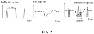
- FIG. 2 illustrates from left to right a diagram of data arrival rate varying with time, a diagram of single link capacity varying with time, and a diagram of latency caused by capacity fluctuation of a single link.
- MLA Multi-Link Aggregation
- Multi-link aggregation can be implemented in many ways, which can be divided into packet-based link aggregation and traffic-based link aggregation.
- frames of a single service flow e.g., all services associated with a given traffic identification (TID)
- TID traffic identification
- the multiple wireless links may be in the same radio frequency (RF) (e.g., 5 GHz band) or in different frequency bands (e.g., one in 2.4 GHz band, another in 5 GHz band or 6 GHz band).
- RF radio frequency
- Each link may be associated with a different physical layer (PHY) and a lower Media Access Control (MAC) layer.
- PHY physical layer
- MAC Media Access Control
- each service flow may be transmitted by using one of a plurality of available wireless links. For example, some data may be transmitted on the first link while being transmitted on the second link.
- the multi-link aggregation has many advantages. Firstly, multiple links can transmit traffic belonging to the same TID at the same time, and channel diversity helps to smoothly transmit traffic and increase peak throughput during link fluctuation. Secondly, data packets on high capacity links can be multiplexed on underutilized links to achieve load balancing and make full use of spectrum resources. In addition, compared with a single link, the multi-link aggregation benefits applications such as wireless VR and interactive multiplayer games which require low latency, short turnaround time and handling burst traffic quickly.
- a method of multi-link aggregation is mainly divided into the synchronous aggregation method and the asynchronous aggregation method.
- an enhanced distributed channel access (EDCA) back-off operation is performed only on a single main link.
- energy detection (ED) which is also referred to as medium detection, is performed on a secondary link before performing data transmission on the main link, if the secondary link is idle, multi-link aggregation transmission is performed, otherwise, data is transmitted only on the main link.
- ED energy detection
- TXOP independent transmission opportunity
- FIG. 3 illustrates a performance simulation diagram under three access modes: a single link access mode (No Aggregation), a multi-link synchronous access mode (Simultaneous (single primary)) and a multi-link asynchronous access mode (Independent). It can be seen from FIG. 3 that under the same conditions, peak throughput in the multi-link asynchronous access mode is the largest, followed by peak throughput in the multi-link synchronous access mode and peak throughput in the single link access mode is the smallest.
- a single link access mode No Aggregation
- a multi-link synchronous access mode Simultaneous (single primary)
- a multi-link asynchronous access mode Independent
- a multi-link logical entity carrying a newly defined multi-link protocol and framework to achieve higher performance requirements is defined.
- This logical entity is called a Multi-Link Device (MLD) which can support the MLA technology described above.
- MLD can include, for example, an access point MLD (AP MLD) and a non-access point MLD (Non-AP MLD) which is also called a station MLD (STAMLD).
- AP MLD access point MLD
- Non-AP MLD non-access point MLD
- STAMLD station MLD
- each subsidiary STA of the STA MLD can perform EDCA competition mechanism independently, and clear channel assessment (CCA) detection among subsidiary STAs is not affected with each other, so it is easier to realize the multi-link aggregation technology.
- CCA clear channel assessment
- an MLD that does not support the STR function which can be called a Non-STR MLD
- a working frequency band interval of the subsidiary STAs of the Non-STR MLD is too small
- IDC Device Coexistence
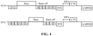
- a method of multi-link aggregation based on Back-off Counter is introduced.
- Each STA for one MLD performs an independent EDCA mechanism on each link.
- the STA can perform synchronous Physical layer Protocol Data Unit (PPDU) transmission. If the BC of an STA on one link is decremented to a counter value of 0, then the counter value of 0 remains unchanged until the BC of an STA on the other link reaches a counter value of 0. While waiting for the BC of the STA on another link to reach a counter value of 0, the STA can continue to monitor states of link medium on the link.
- the PPDU is an Aggregate Media Access Control (MAC) Protocol Data Unit (PDU), i.e., A-MPDU.
- a physical header part of the PPDU includes a Preamble and a Packet Layer Control Protocol (PLCP) header, one bit of the PLCP header indicates that the PPDU is A-MODU, and a MAC part of the PPDU may include a plurality of sub-frames.
- MAC Media Access Control
- A-MPDU Aggregate Media Access Control
- a physical header part of the PPDU includes a Preamble and a Packet Layer Control Protocol (PLCP) header, one bit of the PLCP header indicates that the PPDU is A-MODU, and a MAC part of the PPDU may include a plurality of sub-frames.
- PLCP Packet Layer Control Protocol
- the first shortcoming is that the success rate of multi-link aggregation is not high.
- a STA of which BC first backs off to a counter value of 0 maintains the counter value unchanged, and completes the access after waiting for the BCs of other STAs to back off to a counter value of 0, thus realizing synchronous multi-link aggregation transmission.
- the BC when the BC first backs off to a counter value of 0 and maintains the counter value of 0 unchanged, it will be occupied by the other STA device (which does not belong to the MLD that is performing the multi-link aggregation function), which results in the failure of the multi-link aggregation.
- the second shortcoming is that the latency is high.
- the multi-link aggregation function of the Non-STR MLD is realized to a certain extent by setting the BC, when the BC backs off to a counter value of 0 and the counter value of 0 maintains unchanged, there will be a large latency for latency-sensitive service flows. Therefore, how to realize multi-link aggregation with high success rate and low latency is an urgent problem to be solved.
- the present disclosure provides a multi-link aggregation scheme, which can solve the problem that the Non STR MLD cannot monitor link states of other links when transmitting or receiving data on one link. Meanwhile, the Non STR MLD obtains link states of other links for which the Non STR MLD is assisted by an access point multi-link device in monitoring, and then performs the multi-link aggregation, which improves the throughput of the system and the success rate of link aggregation.
- FIG. 5 illustrates an interaction diagram of a method 300 of multi-link aggregation provided according to an embodiment of the present disclosure. As illustrated in FIG. 5 , the method 300 includes at least some of the following operations.
- a station multi-link device transmits first information to an access point multi-link device.
- the first information is used for determining at least one target link for which the station multi-link device is required to be assisted by the access point multi-link device in monitoring.
- a plurality of links are established between the station multi-link device and the access point multi-link device. If there is a large number of burst traffic on the station multi-link device side and the traffic need to be transmitted to the access point multi-link device in a short time (such as real-time video stream, VR, AR and other scenarios), the station multi-link device may adopt a multi-link aggregation transmission mode.
- the number of links established between the station multi-link device and the access point multi-link device is not specifically limited in the embodiments of the present disclosure.
- the number of links established between the station multi-link device and the access point multi-link device may be 2, 3, or more, or the like.
- the plurality of links may be in the same frequency band, or may be in different frequency bands. There are no limits made thereto in the embodiments of the preset disclosure.
- the multi-link aggregation transmission of the embodiments of the present disclosure may be packet-based link aggregation, traffic-based link aggregation, or link aggregation based on other modes.
- the link aggregation mode is not limited in the present disclosure.
- the station multi-link device may include two stations, or the station multi-link device may further include three or more stations. There are no limits made thereto in the embodiments of the preset disclosure.
- the station multi-link device includes a plurality of stations, each of which corresponds to a link, and each station can perform multi-link aggregation transmission through the link corresponding to the station.
- a station may perform multi-link aggregation transmission with the acquisition of TXOP ownership of a link corresponding to the station.
- the station obtains TXOP ownership of a link corresponding to the station through an EDCA contention mechanism or TXOP ownership of a link corresponding to the station is transferred to the station device by the access point multi-link device.
- the access point multi-link device may transfer the TXOP ownership of the link to a station multi-link device by transmitting a multi-user request to send (MU-RTS) to the station multi-link device.
- MU-RTS multi-user request to send
- the access point multi-link device may include two access points, or the access point multi-link device may include three or more access point devices. There are no limits made thereto in the embodiments of the preset disclosure.
- the station multi-link device does not support the STR function, and the access point multi-link device supports the STR function. This is recorded as the first scenario.
- the technical solutions of the embodiments of the present disclosure can be used for performing the multi-link aggregation transmission.
- all STAs of a plurality of STAs of the station multi-link device used for multi-link aggregation obtain TXOP ownerships of links corresponding to the STAs.
- the station multi-link device may perform multi-link aggregation transmission by using the synchronous access mode described above.
- the station multi-link device supports the STR function
- the access point multi-link device supports the STR function. This is recorded as the second scenario.
- the station multi-link device when the station multi-link device performs uplink multi-link aggregation, one or more STAs requiring uplink multi-link aggregation in the station multi-link device are in a doze state for the consideration of energy saving.
- the station multi-link device can transmit first information to the access point multi-link device for requesting the access point multi-link device to assist in monitoring states of links corresponding to STAs in the station multi-link device.
- the STA changed from a doze state to a wake state can directly perform uplink multi-link aggregation after receiving feedback information from the access point multi-link device without performing a normal EDCA competition mechanism.
- the at least one target link for which the station multi-link device is required to be assisted by the access point multi-link device in monitoring may include links of which TXOP ownerships are not obtained by STAs in the station multi-link device. This situation can be applied to the first scenario mentioned above.
- the station multi-link device includes an STA1 corresponding to a link 1, an STA2 corresponding to a link 2, the STA1 obtains TXOP ownership of the link 1, and the STA2 does not obtain TXOP ownership of the link 2, the target link may include the link 2. That is to say, the access point multi-link device assists in monitoring a link state of the link 2.
- the at least one target link for which the station multi-link device is required to be assisted by the access point multi-link device in monitoring may include links corresponding to STAs in a doze state in the station multi-link device. This situation can be applied to second scenario above.
- the target link may include the link 2. That is to say, the access point multi-link device assists in monitoring a link state of the link 2.
- the station multi-link device may generate first information based on information of at least one target link for which the station multi-link device is required to be assisted by the access point multi-link device in monitoring, and further transmit the first information to the access point multi-link device.
- the station multi-link device may transmit the first information on a link of which TXOP ownership is obtained by the station multi-link device.
- the TXOP ownership of the link may be obtained through an EDCA contention mechanism.
- the information of the at least one target link can be indicated by a bitmap, or the first information can directly include link ID information of the at least one target link, and the indication mode of the target link is not specifically limited in the present disclosure.
- the first information includes at least one of first indication information or a first bitmap.
- the first indication information is used for indicating that the at least one target link identified by the first bitmap is used for uplink multi-link aggregation.
- the first bitmap includes a plurality of bits, each of the plurality of bits corresponds to a link, and different values of the bit are used for indicating whether the link corresponding to the bit is a target link for which the station multi-link device is required to be assisted by the access point multi-link device in monitoring.
- a value of the first indication information being a first value indicates that a target link identified by the first bitmap is used for uplink multi-link aggregation, and the value of the first indication information being other values indicates that information carried by the first bitmap is not used for uplink multi-link aggregation.
- contents carried in the first bitmap are interpreted based on information of the target link
- the value of the first indication information is the other values
- the contents carried in the first bitmap are interpreted based on other meanings.
- the first bitmap may include M bits, each bit corresponds to a link, or each bit corresponds to a link ID, and values of each bit are used for indicating whether the link corresponding to the bit is a target link. For example, a value of a bit being 1 represents that a link corresponding to the bit is a target link, and the value of a bit being 0 represents that a link corresponding to the bit is not the target link.
- the first bitmap includes 6 bits, which are denoted as B5 to B0, respectively corresponding to link 5 to link 0, and the links based on which the station multi-link device need to perform multi-link aggregation include the link 0 to the link 3. If STAs in the station multi-link device obtain TXOP ownerships of the link 0 and the link 3, but does not obtain TXOP ownerships of the link 1 and the link 2, the target link for which the station multi-link device is required to be assisted by the access point multi-link device in monitoring includes the link 1 and the link 2. In this case, when the station multi-link device generates first information, bits corresponding to the link 1 and the link 2 may be set to 1. That is to say, B 1 and B2 are set to 1, and other bits are set to 0, so as to instruct the access point multi-link device to assist in monitoring link states of the link 1 and the link 2.
- the station multi-link device transmits the first information over any communication frame for interacting with the access point multi-link device. There are no limits made thereto in the embodiments of the preset disclosure.
- the first information is contained in a first frame.
- the first frame is one of: a control wrapper frame, a management frame, and a data frame.
- the data frame may be a Quality of Service (QoS) data frame, or a QoS Null frame.
- QoS Quality of Service
- QoS Null a QoS Null frame.
- the first information may be contained in any field including reserved bits or fields containing undefined values (or invalid values, reserved values) in any of the above frames as long as the number of reserved bits is sufficient to carry the first information.
- the specific position of the first information in the above frames is not limited in the present disclosure.
- the first information is contained in an aggregate (A) control subfield in a high throughput (HT) control field of the first frame.
- A aggregate
- HT high throughput
- the A control subfield includes at least one of a control identification (ID) field or a first bitmap field.
- the control ID field is used for carrying the first indication information
- the first bitmap field is used for carrying the first bitmap.
- a value of the control ID field when a value of the control ID field is a first value, it represents that the first bitmap field is used for uplink multi-link aggregation. In this case, the first bitmap field is used for determining the at least one target link for which the station multi-link device is required to be assisted by the access point multi-link device in monitoring.
- the first value is a reserved value of the control ID field.
- the first value may be 0111.
- the number of bits occupied by the first bitmap field may be determined based on the maximum number of links corresponding to the multi-link aggregation.
- Each bit in the first bitmap field can correspond to a link, or a link ID, and the value of each bit is used for indicating whether the link corresponding to the bit is a target link for which the station multi-link device is required to be assisted by the access point multi-link device in monitoring.
- FIG. 6 illustrates an example of a frame format of a control wrapper frame.
- control wrapper frame in FIG. 6 is only an example, and the control wrapper frame may also be updated in the evolution of standards, in which case the carrying position of the first information in the control wrapper frame may also be adaptively adjusted. There are no limits made thereto in the embodiments of the preset disclosure.
- control wrapper frame can include the following fields.
- the number of bytes occupied by each of the above fields is 2, 2, 6, 2, 4, variable and 4 in sequence.
- a type value in the Frame Control field of the control wrapper frame is set to 01 and a subtype value is set to 0111.
- the HT Control field of the control wrapper frame can further include the A control subfield.
- the A control subfield may occupy the upper 30 bits of the 4 bytes of the HT Control field, e.g., B31 to B2.
- the first information may be carried in the A control subfield in the HT Control field of the control wrapper frame.
- the A control subfield can be set to include a control ID field and a first bitmap field.
- control ID field may include 4 bits (e.g., B5 to B2)
- first bitmap field may include 6 bits (e.g., B11 to B6), or other number of bits. The number of bits may be determined based on the maximum number of target links required to be monitored.
- control ID field including 4 bits and the first bitmap field including 6 bits are taken as an example. There are no limits made thereto in the embodiments of the preset disclosure.
- a value of the control ID field (i.e., B5 to B2) being "0111" represents that the first bitmap field (i.e., B11 to B6) is used for uplink multi-link aggregation, that is, contents carried in the first bitmap field (i.e., B11 to B6) are used for determining information of the target links for which the station multi-link device is required to be assisted by the access point multi-link device in monitoring.
- the access point multi-link device may parse the first bitmap field in the A control subfield and obtain the information of the target link. Otherwise, the access point multi-link device does not perform the operation of assisting the multi-link aggregation.
- the A control subfield may further include a reserved field.
- FIG. 7 illustrates an example of a frame format of a management frame.
- the frame format of the management frame in FIG. 7 is only an example, and the management frame may also be updated in the evolution of standards, in which case the carrying position of the first information in the management frame can also be adaptively adjusted. There are no limits made thereto in the embodiments of the preset disclosure.
- the management frame may include an action frame, or may include other management frames. There are no limits made thereto in the embodiments of the preset disclosure.
- the management frame can include the following fields: Frame Control, duration/ID, Address 1, Address 2, Address 3, Sequence Control, HT Control, Frame Body and Frame Check Sequence (FCS).
- FCS Frame Body and Frame Check Sequence
- the number of bytes occupied by each of the above fields is 2, 2, 6, 6, 6, 2, 4, variable and 4 in sequence.
- a type value in the Frame Control field of the management frame is set to 00 and a subtype value is set to 1101.
- the HT Control of the management frame can include the A control subfield.
- the A control subfield may occupy the upper 30 bits of the 4 bytes of the HT Control filed, e.g., B31 to B2.
- the first information may be carried in an A control subfield in the HT Control field of the management frame.
- the A control subfield can be set to include a control ID field and a first bitmap field.
- control ID field may include 4 bits (e.g., B5 to B2)
- first bitmap field may include 6 bits (e.g., corresponding to B11 to B6), or other number of bits. The number of bits may be determined based on the maximum number of target links required to be monitored.
- control ID field including 4 bits and the first bitmap field including 6 bits are taken as an example. There are no limits made thereto in the embodiments of the preset disclosure.
- a value of the control ID field (i.e., B5 to B2) being "0111" represents that the first bitmap field (i.e., B11 to B6) is used for uplink multi-link aggregation, that is, contents carried in the first bitmap field (i.e., B11 to B6) are used for determining information of the target links for which the station multi-link device is required to be assisted by the access point multi-link device in monitoring.
- the access point multi-link device may parse the first bitmap field in the A control subfield and obtain the information of the target link. Otherwise, the access point multi-link device does not perform the operation of assisting the multi-link aggregation.
- the A control subfield may further include a reserved field.
- FIG. 8 illustrates an example of a frame format of a data frame.
- the frame format of the data frame in FIG. 8 is only an example, and the data frame may also be updated in the evolution of standards, in which case the carrying position of the first information in the data frame can also be adaptively adjusted. There are no limits made thereto in the embodiments of the preset disclosure.
- the data frame can include the following fields.
- a type value in the Frame Control field of the data frame is set to 10 and a subtype value is set to 1000, so as to indicate that the data frame includes payloads.
- a type value in the Frame Control field of the data frame is set to 10 and a subtype value is set to 1100, so as to indicate that the data frame does not include payloads.
- the HT Control of the data frame can include the A control subfield.
- the A control subfield may occupy the upper 30 bits of the 4 bytes of the HT Control, e.g., B31 to B2.
- the first information may be carried in an A control subfield in the HT Control field of the data frame.
- the A control subfield can be set to include a control ID field and a first bitmap field.
- control ID field may include 4 bits (e.g., B5 to B2)
- first bitmap field may include 6 bits (e.g., corresponding to B11 to B6), or other number of bits. The number of bits may be determined based on the maximum number of target links required to be monitored.
- control ID field including 4 bits and the first bitmap field including 6 bits are taken as an example. There are no limits made thereto in the embodiments of the preset disclosure.
- a value of the control ID field (i.e., B5 to B2) being "0111" represents that the first bitmap field (i.e., B11 to B6) is used for uplink multi-link aggregation, that is, contents carried in the first bitmap field (i.e., B11 to B6) are used for determining information of the target links for which the station multi-link device is required to be assisted by the access point multi-link device in monitoring.
- the access point multi-link device may parse the first bitmap field in the A control subfield and obtain the information of the target link. Otherwise, the access point multi-link device does not perform the operation of assisting the multi-link aggregation.
- the A control subfield may further include a reserved field.
- the access point multi-link device receives the first information transmitted by the station multi-link device. Further, in S302, the first information is parsed to obtain the information of the target link, and the target link is monitored to determine the link state of the target link. For example, whether the target link is idle or not is determined.
- the access point multi-link device may generate second information based on the link state of the target link.
- the first information is carried in the A control field in the HT Control field in the management frame, and the access point multi-link device may obtain the first information from the A control field in the HT Control field in the management frame. If the value of B5 to B2 in the A control field is 0111, the access point multi-link device can determine that contents carried in B11 to B6 is used for determining information of the target links for which the station multi-link device is required to be assisted by the access point multi-link device in monitoring, and the access point multi-link device further obtains information in B11 to B6. If the value of B11 to B6 is 000110, corresponding to link 5 to link 0 respectively, the access point multi-link device can determine that link 1 and link 2 are the target links required to be monitored.
- the AP2 can start Point Interframe Space (PIFS) Energy Detection (ED), and if it is detected that the link 2 is in an idle state, the AP2 generates second information and transmits the second information to the station multi-link device. Otherwise, the AP2 continues the above operations after performing a normal EDCA mechanism.
- NAV Network Allocation Vector
- ED Point Interframe Space
- the method 300 further includes following operations.
- the station multi-link device receives second information transmitted by the access point multi-link device.
- the second information is used for indicating at least one link state of the at least one target link for which the station multi-link device is required to be assisted by the access point multi-link device in monitoring.
- information of the at least one link state of the at least one target link can be indicated by a bitmap, or the second information can directly include the link ID of the target link and the information of the link state corresponding to the target link.
- the present disclosure does not specifically limit the indication mode of the link state of the target link.
- the number of target links fed back by the second information may be the same as or may be different from the number of target links, for which the station multi-link device is required to be assisted by the access point multi-link device in monitoring, in the first information.
- the access point multi-link device may only feedback link states of a portion of the links.
- the access point multi-link device may not reply the second information to the station multi-link device.
- the second information includes at least one of second indication information or a second bitmap.
- the second indication information is used for indicating whether the second information includes the information of the at least one link state of the at least one target link.
- the second bitmap includes a plurality of bits, each of the plurality of bits corresponds to at least one link, and different values of the bit are used for indicating whether a link corresponding to the bit is in an idle state.
- the second indication information may be 1 bit, and the value of the 1 bit is used for indicating whether the second information includes the information of the at least one link state of the at least one target link.
- the value of the 1 bit being 1 represents that the second information includes the information of the at least one link state of the at least one target link
- the value of the 1 bit being 0 represents that the second information does not include the information of the at least one link state of the at least one target link.
- the second bitmap may include M bits, each bit corresponds to a link, or each bit corresponds to a link ID, the value of each bit is used for indicating a link state of the link corresponding to the bit. For example, if a value of a bit is 1, it represents that a link state of a link corresponding to the bit is an idle state, and if the value of a bit is 0, it represents that a link state of a link corresponding to the bit is a busy state.
- the number of bits corresponding to each link in the second bitmap may be determined based on the number of link states of each link. For example, if there are two link states, each link may correspond to one bit, or if there are more than two link states, each link may correspond to more than one bit. There are no limits made thereto in the embodiments of the preset disclosure.
- the second bitmap includes 6 bits, which are denoted as B5 to B0, respectively corresponding to link 5 to link 0.
- the at least one target link for which the station multi-link device is required to be assisted by the access point multi-link device in monitoring includes the link 1 and the link 2. If a link state of the link 1 is idle and a link state of the link 2 is busy, when the access point multi-link device generates the second information, B 1 can be set to 1, B2 can be set to 0, and other bits are not processed (the default value of other bits can be 0). After obtaining the second information, the station multi-link device can parse the second information to obtain the link state corresponding to the target link, so as to perform multi-link aggregation transmission.
- the access point multi-link device transmits the second information over any communication frame for interacting with the station multi-link device. There are no limits made thereto in the embodiments of the preset disclosure.
- the second information is contained in a control frame or a management frame.
- control frame includes a Block Acknowledgement (BA) frame or a control wrapper frame.
- BA Block Acknowledgement
- the management frame includes an action frame.
- control frame and the management frames are only examples and in other embodiments the second information may also be carried in other control frames or management frames. There are no limits made thereto in the embodiments of the preset disclosure.
- FIG. 9 illustrates a frame format of a BA frame.
- the frame format of the BA frame in FIG. 9 is only an example, and the BA frame may also be updated in the evolution of standards, in which case the carrying position of the second information in the BA frame may also be adaptively adjusted. There are no limits made thereto in the embodiments of the preset disclosure.
- the BA frame may include the following fields: Frame Control, duration, Receiver Address (RA), Transmitter Address (TA), BA Control, BA information and FCS.
- the number of bytes occupied by each of the above fields is 2, 2, 6, 6, 2, variable and 4 in sequence.
- the BA control field of the BA frame may further include the following subfields: BA Acknowledgement Policy (BA ACK Policy), Multi-TID, Compressed Bitmap, Groupcast with retries (GCR), Reserved and TID information (TID_INFO).
- BA ACK Policy BA Acknowledgement Policy
- Multi-TID Multi-TID
- Compressed Bitmap Compressed Bitmap
- GCR Groupcast with retries
- Reserved and TID information TID information
- the second information may be carried in the reserved subfield in the BA control field of the BA frame.
- the reserved subfield may be set to include a feedback indication field and a second bitmap field.
- the feedback indication field is used for carrying the second indication information
- the second bitmap field is used for carrying the second bitmap.
- the feedback indication field may include 1 bit (e.g., B4)
- the second bitmap field may include 6 bits (e.g., B10 to B5), or other number of bits. The number of bits may be determined based on the maximum number of target links required to be monitored.
- the feedback indication field including 1 bit and the second bitmap field including 6 bits are taken as an example. There are no limits made thereto in the embodiments of the preset disclosure.
- the reserved subfield can further include a reserved field.
- a value of the feedback indication field (e.g., B4) being "1" represents that the second bitmap field (e.g., B10 to B5) includes information of link states of target links, or that contents carried in the second bitmap field (e.g., B10 to B5) are used for determining link states of target links, or that the BA frame includes information of link states of target links.
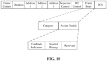
- FIG. 10 illustrates a frame format of an action frame.
- the frame format of the action frame in FIG. 10 is only an example, and the action frame may also be updated in the evolution of standards, in which case the carrying position of the second information in the action frame can also be adaptively adjusted. There are no limits made thereto in the embodiments of the preset disclosure.
- the action frame can include the following fields: Frame Control, duration/ID, Address 1, Address 2, Address 3, Sequence Control, HT Control, Frame Body and FCS.
- the number of bytes occupied by each of the above fields is 2, 2, 6, 6, 6, 2, 4, variable and 4.
- a type value in the Frame Control field of the action frame is set to 00, a subtype value is set to 1101, and a Category subfield is set to 00010110.
- the Frame Body field of the action frame can further include the following subfields: Category and action details.
- the number of bytes occupied by each of the above subfields is 1 and variable in sequence.
- the second information may be carried in the action details subfield in the Frame Body field of the action frame.
- the action details subfield may be set to include a feedback indication field and a second bitmap field.
- the feedback indication field is used for carrying the second indication information
- the second bitmap field is used for carrying the second bitmap.
- the feedback indication field may include 1 bit (e.g., B4)
- the second bitmap field may include 6 bits (e.g., B10 to B5), or other number of bits. The number of bits may be determined based on the maximum number of target links required to be monitored.
- the feedback indication field including 1 bit and the second bitmap field includes 6 bits as an example. There are no limits made thereto in the embodiments of the preset disclosure.
- a value of the feedback indication field (e.g., B4) being "1" represents that the second bitmap field (e.g., B10 to B5) includes information of link states of target links, or that contents carried in the second bitmap field (e.g., B10 to B5) are used for determining link states of target links, or that the action frame includes information of link states of target links.
- the action details subfield can further include a reserved field.
- the second information may be transmitted through a link of which TXOP ownership is obtained by the station multi-link device.
- the station multi-link device includes an STA1 and an ST2, the STA1 obtains TXOP ownership of a link 1, the STA2 does not obtain TXOP ownership of a link 2, the STA1 may transmit first information to an AP1 in the access point multi-link device through the link 1 for instructing the access point multi-link device to assist in monitoring a link state of the link 2, and after the access point multi-link device determines the link state of the link 2, the AP1 may transmit second information through the link 1 for feedback of the link state of the link 2.
- the access point multi-link device may also notify the station multi-link device of the link states of the target links through implicit information which may not include a second information field. Performing feedback in this way does not need to change the frame format.
- the implicit information is transmitted on a link of which TXOP ownership is not obtained by the station multi-link device (e.g., the link may include a link in an idle state in target links required to be monitored).
- the station multi-link device includes an STA1 and an ST2, the STA1 obtains TXOP ownership of a link 1, the STA2 does not obtain TXOP ownership of a link 2, the STA1 may transmit first information to an AP1 in the access point multi-link device through the link 1 for instructing the access point multi-link device to assist in monitoring a link state of the link 2, and if the access point multi-link device determines that the link 2 is in an idle state, an AP2 may transmit implicit information through the link 2 for indicating that the link 2 is in an idle state.
- the implicit information may include a trigger frame or the implicit information may further include other frames that can implicitly indicate link states, such as data frames.
- the access point multi-link device determines the link state of the target link in the first information, and further transmits a data frame on the target link in an idle state. If the station multi-link device receives the data frame replied by the access point multi-link device, the station multi-link device may determine that the target link used for transmitting the data frame is in an idle state.
- the trigger frame may include a MU-RTS.
- the access point multi-link device feeds back, through the MU-RTS, to the station multi-link device at least one link state of at least one target link for which the station multi-link device is required to be assisted by the access point multi-link device in monitoring.
- the access point multi-link device feeds back, through the MU-RTS, to the station multi-link device at least one link state of at least one target link for which the station multi-link device is required to be assisted by the access point multi-link device in monitoring.
- the access point multi-link device may transmit the MU-RTS through a target link in an idle state.
- the station multi-link device can determine a link in an idle state based on the link through which the MU-RTS is received.
- the MU-RTS is further used by the access point multi-link device to transfer TXOP ownership of the link transmitting the MU-RTS to the station multi-link device.
- the access point multi-link device may also transmit a CTS to self frame on a target link that is in an idle state, so as to notify other devices competing for the target link that the access point multi-link device has obtained TXOP ownership of the target link, and therefore preventing the target link from being occupied by other devices, and improving the success rate of multi-link aggregation.
- the method 300 further includes an operation S304.
- the station multi-link device performs multi-link aggregation transmission based on the at least one link state indicated in the second information.
- the link in the idle state can be obtained by parsing the second information, and the multi-link aggregation transmission can be performed through the link in the idle state, thereby improving the system throughput.
- the station multi-link device includes an STA1 and an STA2, the STA1 corresponds to a link 1 and the STA2 corresponds to a link 2, and the access point multi-link device (STR AP MLD) may include an AP1 and an AP2, the AP1 corresponds to link 1 and the AP2 corresponds to the link 2.
- the link 1 and the link 2 may correspond to the same frequency band or may correspond to different frequency bands.
- the station multi-link device performs a normal EDCA contention mechanism on the link 1 and the link 2.
- the BC of the station STA1 on the link 1 decreases to 0, it is found that the link 2 is occupied by other devices and the link 2 is in a busy state. If the station multi-link device continues to wait for the BC of another link to reach 0, the aforementioned problem will be caused.
- the station multi-link device can generate first information. The specific implementation of the first information is described with reference to the related description of the foregoing embodiments and will not be repeated here.
- the STA1 obtains the TXOP ownership of the link 1. Further, the STA1 can transmit an uplink multi-link aggregation frame (denoted as a UA frame) to the access point multi-link device through the link 1.
- the UA frame includes the first information, and the UA frame can be any of frames in the foregoing embodiments for carrying the first information and the UA frame is used for requesting the access point multi-link device to assist in monitoring the link state of the link 2.
- the STA1 can also transmit PPDU data on the link 1 to the AP1.
- the PPDU data may be PPDU1 and PPDU2.
- the AP1 can also reply the BA frame to the STA1 on the link 1.
- the access point multi-link device can obtain, from the first information, the information of the link required to be monitored, and can further monitor the link 2 to determine the link state of the link 2. For example, if the link 2 is in an idle state, the AP1 can transmit second information to the STA1 through the link 1, or the AP2 can transmit implicit information (excluding the second information field) through the link 2. For example, the AP2 indicates that the link 2 is in an idle state by transmitting the MU-RTS through the link 2. Meanwhile, the AP2 transfers the TXOP ownership of the link 2 to the STA2, and the STA2 obtains the TXOP ownership of the link 2.
- the AP2 may first transmit the CTS to self frame on the link 2 for notifying other devices competing for the link 2 that the AP2 has obtained TXOP ownership of the link 2, so as to prevent the link 2 from being occupied by other devices.
- the STA2 after receiving the MU-RTS, can transmitting the CTS frame on the link 2 as a reply, as illustrated in FIG. 11 , or, the STA2 does not transmitting the CTS frame as a reply, as illustrated in FIG. 12 .
- the station multi-link device may perform multi-link aggregation transmissions through the link 1 and the link 2. For example, PPDU3 is transmitted through the link 1 while PPDU4 is transmitted through the link 2.
- the method further includes following operations.
- the access point multi-link device determines, based on preamble related information in a first data unit, end time of the first data unit.
- the first data unit is received on a first link.
- the at least one of target link does not include the first link, and the second link is in the idle state during a time period of receiving the first data unit, or the second link is transformed from a busy state to the idle state during a time period of receiving the first data unit.
- the access point multi-link device determines, based on the end time of the first data unit, at least one of the number of CTS to self frames to be transmitted or a mode of transmitting the CTS to self frame. End time of a last CTS to self frame is aligned with the end time of the first data unit.
- the first link is a link of which TXOP ownership is obtained by the station multi-link device, and the TXOP ownership of the first link is obtained through an EDCA mechanism.
- the transmission mode of the CTS to self frame can include the selected frame format, MCS, and whether physical layer padding is needed (for example, padding by using Signal extension field), etc.
- the AP2 when the AP2 detects that the link 2 is in an idle state, the AP2 calculates, based on preamble-related information of the PPDU2, end time of the PPDU2, the number of CTS to self frames to be transmitted and a transmission mode of the CTS to self frame, so to ensure that the end time of the PPDU2 is aligned with the end time the CTS to self frames, and then the AP2 transmits the CTS to self frames.
- the access point multi-link device can determine, based on preamble related information of the PPDU2, end time of PPDU2; calculate, based on the end time of PPDU2, the number of CTS to self frames to be transmitted on the link 2 and a frame format, a modulation mode adopted by each CTS to self frame, and whether the Signal extension field is used for padding, etc., so as to ensure that the tail of PPDU2 and CTS to self frame are aligned at the end.
- a difference of end times of the two PPDUs is less than or equal to 8 ⁇ s ((aSIFTime + aSignalExtension)/2)
- the end times of two PPDUs can be considered to be aligned.
- the aSIFSTime represents the time of Short Interframe Space and the aSignalExtension represents the time occupied by padding felids.
- the method further includes following operations.
- the BA frame and the MU-RTS are transmitted, so as to ensure that end time of the BA frame and end time of the MU-RTS are aligned.
- BA block acknowledgement
- MU-RTS multi-user request to send
- the BA frame transmitted by the access point multi-link device on the link 1 and the MU-RTS transmitted by the access point multi-link device on the link 2 also need to satisfy tail alignment.
- a length of the BA frame is at least 22 bytes (including Frame Control, Duration, RA, TA, BA Control and FCS), and a length of the MU-RTS (including Frame Control, Duration, RA, TA, Padding and FCS) is at least 20 bytes, so the tail alignment of the BA and the MU-RTS at the end can be achieved (or guaranteed) by filling the Padding field.
- the station multi-link device is assisted by the access point multi-link device in monitoring links.
- the problem that the Non STR MLD cannot monitor link states of other links when transmitting or receiving data in one link is solved.
- the Non STR MLD performs the multi-link aggregation, which improves the throughput of the system and the success rate of link aggregation.
- FIG. 13 illustrates a block diagram of a station multi-link device 400 according to an embodiment of the present disclosure. As illustrated in FIG. 13 , the station multi-link device 400 includes a communication unit 410.
- the communication unit 410 is configured to transmit first information to an access point multi-link device.
- the first information is used for determining at least one target link for which the station multi-link device is required to be assisted by the access point multi-link device in monitoring.
- the TXOP ownership of the link is obtained through an enhanced distributed channel access (EDCA) mechanism.
- EDCA enhanced distributed channel access
- the ID information of the at least one target link is indicated by a bitmap.
- the first information further includes first indication information.
- the first indication information is used for indicating that the at least one target link identified by the first bitmap is used for uplink multi-link aggregation.
- the first information is contained in a first frame.
- the first frame is one of: a control wrapper frame, a management frame or a data frame.
- the first information is contained in an aggregate (A) control subfield in a high throughput (HT) control field of the first frame.
- A aggregate
- HT high throughput
- the first value is a reserved value of the control ID field.
- the communication unit 410 is further configured to receive second information transmitted by the access point multi-link device.
- the second information is used for indicating at least one link state of the at least one target link for which the station multi-link device is assisted by the access point multi-link device in monitoring.
- information of the at least one link state of the at least one target link is represented by a bitmap.
- the second information includes a second bitmap.
- the second bitmap includes a plurality of bits, each of the plurality of bits corresponds to at least one link, and different values of each bit are used for indicating whether at least one link corresponding to the bit is in an idle state.
- the second information includes second indication information.
- the second indication information is used for indicating whether the second information includes the information of the at least one link state of the at least one target link.
- the second information is contained in a control frame or a management frame.
- control frame includes a block acknowledgement (BA) frame or a control wrapper frame.
- BA block acknowledgement
- the second information is contained in a reserved subfield in a BA control field of the BA frame.
- the reserved field includes a feedback indication field and a second bitmap field.
- the feedback indication field is used for indicating whether the BA frame includes information of the at least one link state of the at least one target link and the second bitmap field is used for the at least one link state of the at least one target link.
- the management frame includes an action frame.
- the second information is contained in an action details field in a frame body field of the action frame.
- the action details field includes at least one of a feedback indication field or a second bitmap field.
- the feedback indication field is used for indicating whether the action frame includes information of the at least one link state of the at least one target link
- the second bitmap field is used for determining the at least one link state of the at least one target link.
- the communication unit 410 is further configured to receive a trigger frame transmitted by the access point multi-link device.
- the trigger frame is used for determining at least one link state of the at least one target link for which the station multi-link device is assisted by the access point multi-link device in monitoring.
- the station multi-link device further includes a processing unit.
- the processing unit is used for determining that a link receiving the trigger frame is in an idle state.
- the trigger frame includes a multi-user request to send (MU-RTS).
- the MU-RTS is further used for the access point multi-link device to transfer to the station multi-link device transmission opportunity (TXOP) ownership of the link for transmitting the MU-RTS.
- TXOP station multi-link device transmission opportunity
- the communication unit 410 is further configured to perform multi-link aggregation transmission based on at least one link state of the at least one target link.
- the station multi-link device further includes a processing unit.
- the processing unit is configured to generate the first information and to parse the second information to obtain the at least one link state of the at least one target link.
- the station multi-link device is assisted by the access point multi-link device in monitoring links.
- the problem that the Non STR MLD cannot monitor link states of other links when transmitting or receiving data in one link is solved.
- the Non STR MLD performs the multi-link aggregation, which improves the throughput of the system and the success rate of link aggregation.
- the communication unit may be a communication interface, transceiver, or an input/output interface of a communication chip or a system-on-chip.
- the processing unit may be one or more processors.
- the station multi-link device 400 may correspond to the station multi-link device in an embodiment of the method of the present disclosure, and the above and other operations and/or functions of each unit in the station multi-link device 400 are used for implementing corresponding procedures of the access point multi-link device in the method 300 illustrated in FIG. 5 to FIG. 12 .
- the above and other operations and/or functions of each unit in the station multi-link device 400 are used for implementing corresponding procedures of the access point multi-link device in the method 300 illustrated in FIG. 5 to FIG. 12 .
- details are not repeated here.
- FIG. 14 illustrates a block diagram of an access point multi-link device 500 according to an embodiment of the present disclosure. As illustrated in FIG. 13 , the access point multi-link device 500 includes a communication unit 510.
- the communication unit 510 is configured to receive first information transmitted by a station multi-link device.
- the first information is used for determining at least one target link for which the station multi-link device is required to be assisted by the access point multi-link device in monitoring.
- the access point multi-link device 500 further includes a processing unit.
- the processing unit is configured to parse the first information to obtain information of the at least one target link in the first information.
- the access point multi-link device 500 further includes a storage unit.
- the storage unit is configured to store the information of the at least one target link, such as, ID information of the at least one target link.
- the access point multi-link device further includes the processing unit.
- the processing unit is configured to monitoring the at least one target link based on the first information to determine the at least one link state of the at least one target link.
- the first information includes a first bitmap.
- the first bitmap includes a plurality of bits, each of the plurality of bits corresponds to at least one link, and different values of the bit are used for indicating whether at least one link corresponding to the bit is at least one target link for which the station multi-link device is required to be assisted by the access point multi-link device in monitoring.
- the first information is contained in a first frame.
- the first frame is one of: a control wrapper frame, a management frame or a data frame.
- the first information is contained in an aggregate (A) control subfield in a high throughput (HT) control field of the first frame.
- A aggregate
- HT high throughput
- the A control subfield includes at least one of a control identification (ID) field or a first bitmap field.
- ID control identification
- a value of the control ID field being a first value represents that the first bitmap field is used for uplink multi-link aggregation, and the first bitmap field is used for determining the at least one target link for which the station multi-link device is required to be assisted by the access point multi-link device in monitoring.
- the communication unit 510 receives one of the control wrapper frame, the action frame, and the data frame, and the control ID in the A control field is "0111"
- the first bitmap field can be parsed to obtain the information of the at least one target link. Otherwise, the communication unit 510 does not perform the operation of assisting the multi-link aggregation.
- the communication unit 510 is further configured to transmit second information to the station multi-link device.
- the second information is used for indicating at least one link state of the at least one target link for which the station multi-link device is assisted by the access point multi-link device in monitoring.
- information of the at least one link state of the at least one target link is represented by a bitmap.
- control frame includes a block acknowledgement (BA) frame or a control wrapper frame.
- BA block acknowledgement
- the second information is contained in a reserved subfield in a BA control field of the BA frame.
- the reserved field includes a feedback indication field and a second bitmap field.
- the feedback indication field is used for indicating whether the BA frame includes information of the at least one link state of the at least one target link and the second bitmap field is used for the at least one link state of the at least one target link.
- the management frame includes an action frame.
- the action details field includes at least one of a feedback indication field or a second bitmap field.
- the feedback indication field is used for indicating whether the action frame includes information of the at least one link state of the at least one target link
- the second bitmap field is used for determining the at least one link state of the at least one target link.
- the trigger frame includes a multi-user request to send (MU-RTS).
- the MU-RTS is further used for the access point multi-link device to transfer to the station multi-link device transmission opportunity (TXOP) ownership of the link for transmitting the MU-RTS.
- TXOP station multi-link device transmission opportunity
- the access point multi-link device 500 further includes a processing unit.
- the processing unit is used for determining, based on preamble related information in a first data unit, end time of the first data unit.
- the first data unit is received on a first link, the at least one of target link does not include the first link.
- the second link is in the idle state during a time period of receiving the first data unit, or the second link is transformed from a busy state to the idle state during a time period of receiving the first data unit.
- the processing unit is further configured to determine, based on the end time of the first data unit, at least one of the number of CTS to self frames to be transmitted or a mode of transmitting the CTS to self frame. End time of a last CTS to self frame is aligned with the end time of the first data unit.
- the first link is a link of which transmission opportunity (TXOP) ownership is obtained by the station multi-link device, and the TXOP ownership of the first link is obtained through an enhanced distributed channel access (EDCA) mechanism.
- TXOP transmission opportunity
- EDCA enhanced distributed channel access
- the access point multi-link device 500 further includes a processing unit.
- the processing unit is configured to: based on a length of a block acknowledgement (BA) frame of the first data unit and a length of a multi-user request to send (MU-RTS), transmit the BA frame and the MU-RTS. End time of the BA frame is aligned with end time of the MU-RTS.
- BA block acknowledgement
- MU-RTS multi-user request to send
- the communication unit may be a communication interface, a transceiver, or an input/output interface of a communication chip or a system-on-chip.
- the processing unit may be one or more processors.
- the access point multi-link device 500 may correspond to the access point multi-link device in the method embodiments of the present disclosure, and the above and other operations and/or functions of each unit in the access point multi-link device 500 are used for implementing corresponding procedures of the access point multi-link device in the method 300 illustrated in FIG. 5 to FIG. 12 .
- the access point multi-link device 500 may correspond to the access point multi-link device in the method embodiments of the present disclosure, and the above and other operations and/or functions of each unit in the access point multi-link device 500 are used for implementing corresponding procedures of the access point multi-link device in the method 300 illustrated in FIG. 5 to FIG. 12 .
- details are not repeated here.
- FIG. 15 illustrates a structural diagram of a communication device 600 provided by an embodiment of the present disclosure.
- the communication device 600 illustrated in FIG. 15 includes a processor 610 configured to invoke a computer program from a memory and execute the computer program to implement the method in the embodiments of the present disclosure.
- the communication device 600 may further include a memory 620.
- a processor 610 configured to invoke a computer program from the memory 620 and execute the computer program to implement the method in the embodiments of the present disclosure.
- the memory 620 may be a separate device independent of the processor 610 or may be integrated in the processor 610.
- the communication device 600 may further include a transceiver 630.
- the processor 610 may control the transceiver 630 to communicate with other devices.
- the processor 610 may control the transceiver 630 to transmit information or data to the other devices or receive information or data transmitted by the other devices.
- the communication device 600 may be specifically the access point multi-link device of the embodiment of the present disclosure, and the communication device 600 may implement corresponding procedures implemented by the access point multi-link device in each method of the embodiment of the present disclosure.
- the transceiver 630 may correspond to a communication unit 510 in the access point multi-link device 500 and the processor 610 may correspond to a processing unit in the access point multi-link device 500.
- the memory 720 may be a separate device independent of the processor 710 or may be integrated in the processor 710.
- the chip 700 may further include an input interface 730.
- the processor 710 may control the input interface 730 to communicate with other devices or chips.
- the processor 710 may control the input interface 730 to obtain information or data transmitted by the other devices or the chips.
- the chip 700 may further include an output interface 740.
- the processor 710 may control the output interface 740 to communicate with other devices or chips.
- the processor 710 may control the output interface 740 to output information or data to the other devices or the chips.
- the chip can be applied to the access point multi-link device in the embodiment of the present disclosure, and the chip can implement corresponding procedures implemented by the access point multi-link device in each method of the embodiment of the present disclosure. For the sake of brevity, details are not repeated here.
- the chip can be applied to the station multi-link device in the embodiment of the present disclosure, and the chip can implement corresponding procedures implemented by the station multi-link device in each method of the embodiment of the present disclosure. For the sake of brevity, details are not repeated here.
- the chip referred to in the embodiments of the present disclosure may also be referred to as a chip at system level, a system chip, a chip system, a system-on-chip or the like.
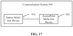
- FIG. 17 illustrates a block diagram of a communication system 900 provided by an embodiment of the present disclosure.
- the communication system 900 includes a station multi-link device 910 and an access point multi-link device 920.
- the station multi-link device 910 may be used to implement the corresponding functions implemented by the station multi-link device in the above method, and the access point multi-link device 920 may be used to implement the corresponding functions implemented by the access point multi-link device in the above method. For the sake of brevity, details are not repeated here.
- a method of multi-link aggregation including: transmitting, by a station multi-link device, first information to an access point multi-link device, wherein the first information is used for determining at least one target link for which the station multi-link device is required to be assisted by the access point multi-link device in monitoring.
- the method of example 4, wherein the first information further includes first indication information, wherein the first indication information is used for indicating that the at least one target link identified by the first bitmap is used for uplink multi-link aggregation.
- example 6 the method of any one of examples 1 to 5, wherein the first information is contained in a first frame, wherein the first frame is one of: a control wrapper frame, a management frame or a data frame.
- example 7 the method of example 6, wherein the first information is contained in an aggregate (A) control subfield in a high throughput (HT) control field of the first frame.
- A aggregate
- HT high throughput
- ID control identification
- first bitmap field is used for determining the at least one target link for which the station multi-link device is required to be assisted by the access point multi-link device in monitoring.
- example 11 the method of example 10, wherein information of the at least one link state of the at least one target link is represented by a bitmap.
- example 13 the method of example 11 or 12, wherein the second information includes second indication information, wherein the second indication information is used for indicating whether the second information includes the information of the at least one link state of the at least one target link.
- example 14 the method of any one of examples 10 to 13, wherein the second information is contained in a control frame or a management frame.
- control frame includes a block acknowledgement (BA) frame or a control wrapper frame.
- BA block acknowledgement
- example 16 the method of example 15, wherein the second information is contained in a reserved subfield in a BA control field of the BA frame
- the reserved field includes a feedback indication field and a second bitmap field, wherein the feedback indication field is used for indicating whether the BA frame includes information of the at least one link state of the at least one target link and the second bitmap field is used for the at least one link state of the at least one target link.
- example 19 the method of example 18, wherein the second information is contained in an action details field in a frame body field of the action frame.
- the action details field includes at least one of a feedback indication field or a second bitmap field, wherein the feedback indication field is used for indicating whether the action frame includes information of the at least one link state of the at least one target link, and the second bitmap field is used for determining the at least one link state of the at least one target link
- the method of example 21, further including: determining, by the station multi-link device, that a link on which the trigger frame is received is in an idle state.
- the trigger frame includes a multi-user request to send (MU-RTS), wherein the MU-RTS is further used for the access point multi-link device to transfer to the station multi-link device transmission opportunity (TXOP) ownership of the link for transmitting the MU-RTS.
- MU-RTS multi-user request to send
- TXOP station multi-link device transmission opportunity
- example 24 the method of any one of examples 1 to 23, further including: performing, by the station multi-link device, multi-link aggregation transmission based on at least one link state of the at least one target link.
- transmitting, by the station multi-link device, the first information to the access point multi-link device includes: transmitting, by the station multi-link device, the first information on a link of which transmission opportunity (TXOP) ownership is obtained by the station multi-link device.
- TXOP transmission opportunity
- a method of multi-link aggregation transmission including: receiving, by an access point multi-link device, first information transmitted by a station multi-link device, wherein the first information is used for determining at least one target link for which the station multi-link device is required to be assisted by the access point multi-link device in monitoring.
- the method of example 27, wherein the first information includes identification (ID) information of the at least one target link.
- ID identification
- example 29 the method of example 28, wherein the ID information of the at least one target link is indicated by a bitmap.
- example 31 the method of any one of examples 27 to 30, wherein the first information is contained in a first frame, wherein the first frame is one of: a control wrapper frame, a management frame or a data frame.
- example 32 the method of example 31, wherein the first information is contained in an aggregate (A) control subfield in a high throughput (HT) control field of the first frame.
- A aggregate
- HT high throughput
- example 35 the method of any one of examples 27 to 34, further including: transmitting, by the access point multi-link device, second information to the station multi-link device, wherein the second information is used for indicating at least one link state of the at least one target link for which the station multi-link device is assisted by the access point multi-link device in monitoring.
- example 36 the method of example 35, wherein the at least one link state of the at least one target link is represented by a bitmap.
- the second information includes a second bitmap, wherein the second bitmap includes a plurality of bits, each of the plurality of bits corresponds to at least one link, and different values of each bit are used for indicating whether at least one link corresponding to the bit is in an idle state.
- control frame includes a block acknowledgement (BA) frame or a control wrapper frame.
- BA block acknowledgement
- example 40 the method of example 39, wherein the second information is comprised in a reserved subfield in a BA control field of the BA frame.
- the reserved field includes a feedback indication field and a second bitmap field, wherein the feedback indication field is used for indicating whether the BA frame includes information of the at least one link state of the at least one target link and the second bitmap field is used for the at least one link state of the at least one target link.
- example 45 the method of any one of examples 27 to 44, further including: transmitting, by the access point multi-link device, a trigger frame to the station multi-link device, wherein the trigger frame is used for indicating at least one link state of the at least one target link.
- the trigger frame includes a multi-user request to send (MU-RTS), wherein the MU-RTS is used for the access point multi-link device to transfer to the station multi-link device transmission opportunity (TXOP) ownership of the link for transmitting the MU-RTS.
- MU-RTS multi-user request to send
- TXOP station multi-link device transmission opportunity
- example 47 the method of any one of examples 27 to 46, further including: transmitting, by the access point multi-link device, a clear to send (CTS) to self frame on a second link, wherein the second link is the target link in an idle state.
- CTS clear to send
- the method of example 48 or 49 further including: transmitting, according to a length of a block acknowledgement (BA) frame of the first data unit and a length of a multi-user request to send (MU-RTS), the BA frame and the MU-RTS, wherein end time of the BA frame is aligned with end time of the MU-RTS.
- BA block acknowledgement
- MU-RTS multi-user request to send
- a station multi-link device including: a communication unit, configured to transmit first information to an access point multi-link device, wherein the first information is used for determining at least one target link for which the station multi-link device is required to be assisted by the access point multi-link device in monitoring.
- an access point multi-link device including: a communication unit, configured to receive first information transmitted by a station multi-link device, wherein the first information is used for determining at least one target link for which the station multi-link device is required to be assisted by the access point multi-link device in monitoring.
- a station multi-link device including: a processor; and a memory for storing a computer program, wherein the processor is configured to invoke and execute the computer program stored in the memory to perform the method of any one of examples 1 to 20.
- a n access point multi-link device including: a processor; and a memory for storing a computer program, wherein the processor is configured to invoke and execute the computer program stored in the memory to perform the method of any one of examples 21 to 38.
- a chip including a processor, wherein the processor is configured to invoke and execute a computer program stored in a memory, so as to cause a device on which the chip is mounted to perform the method of any one of examples 1 to 20.
- a chip including a processor, wherein the processor is configured to invoke and execute a computer program stored in a memory, so as to cause a device on which the chip is mounted to perform the method of any one of examples 21 to 38.
- a computer-readable storage medium for storing a computer program that causes a computer to perform the method of any one of examples 1 to 20.
- a computer-readable storage medium for storing a computer program that causes a computer to perform the method of any one of claims 21 to 38.
- example 59 there is provided a computer program product, including computer program instructions that cause a computer to perform the method of any one of examples 1 to 20.
- example 60 there is provided a computer program product, including computer program instructions that cause a computer to perform the method of any one of examples 21 to 38.
- example 61 there is provided a computer program, wherein the computer program causes a computer to perform the method of any one of examples 1 to 20.
- the processor of the embodiment of the present disclosure may be an integrated circuit chip with signal processing capability.
- the operations of the foregoing method embodiments may be completed by indications in the form of software or the integrated logic circuits of the hardware in the processor.
- the above-mentioned processor may be a general-purpose processor, a digital signal processor (DSP), an application specific integrated circuit (ASIC), a field programmable gate array (FPGA) or other programming logic devices, discrete gates or transistor logic devices, or discrete hardware components.
- DSP digital signal processor
- ASIC application specific integrated circuit
- FPGA field programmable gate array
- the methods, operations, and logical block diagrams disclosed in the embodiments of the present disclosure may be implemented or executed.
- the general-purpose processor may be a microprocessor or the processor may further be any conventional processor or the like.
- the operations of the method disclosed in the embodiments of the present disclosure may be directly embodied as being executed and completed by a hardware decoding processor, or executed and completed by a combination of hardware and software modules in the decoding processor.
- the software module may be located in a mature storage medium in the field such as a random access memory, a flash memory, a read-only memory, a programmable read-only memory, or an electrically erasable programmable memory or a register.
- the storage medium is located in the memory, and the processor reads the information in the memory and completes the operations of the above-mentioned method in combination with its hardware.
- the memory in the embodiment of the present disclosure may be a volatile memory or a non-volatile memory, or may include both volatile and non-volatile memory.
- the non-volatile memory may be a read-only memory (ROM), a programmable ROM (PROM), an erasable PROM (EPROM), an electrically EPROM (EEPROM) or a flash memory.
- the volatile memory may be a random access memory (RAM), which is used as an external cache.
- RAM direct rambus RAMs
- SRAM static RAMs
- DRAM dynamic RAMs
- SDRAM synchronous DRAMs
- DDR SDRAM double data rate SDRAMs
- ESDRAM enhanced SDRAMs
- SLDRAM synchlink DRAMs
- DR RAM direct rambus RAMs
- the memory in the embodiment of the present disclosure may further be a static RAM (SRAM), a dynamic RAM (DRAM), a synchronous DRAM (SDRAM), a double data rate SDRAM (DDR SDRAM), an enhanced SDRAM (ESDRAM), a synch link DRAM (SLDRAM) or a direct rambus RAM (DR RAM), etc.
- SRAM static RAM
- DRAM dynamic RAM
- SDRAM synchronous DRAM
- DDR SDRAM double data rate SDRAM
- ESDRAM enhanced SDRAM
- SLDRAM synch link DRAM
- DR RAM direct rambus RAM
- the embodiment of the present disclosure further provides a computer-readable storage medium for storing computer programs.
- the computer program product may be applied to the access point multi-link device in the embodiment of the present disclosure, and the computer program instructions cause a computer to execute the corresponding procedures implemented by the access point multi-link device in each method of the embodiment of the present disclosure.
- the computer program instructions cause a computer to execute the corresponding procedures implemented by the access point multi-link device in each method of the embodiment of the present disclosure.
- the computer program product may be applied to the station multi-link device in the embodiment of the present disclosure, and the computer program instructions cause a computer to execute the corresponding procedures implemented by the station multi-link device in each method of the embodiment of the present disclosure.
- the computer program instructions cause a computer to execute the corresponding procedures implemented by the station multi-link device in each method of the embodiment of the present disclosure.
- the embodiment of the present disclosure further provides a computer program product including computer program instructions.
- the computer program product may be applied to the access point multi-link device in an embodiment of the present disclosure, and the computer program instructions cause a computer to execute corresponding procedures implemented by the access point multi-link device in each method of the embodiment of the present disclosure.
- the computer program instructions cause a computer to execute corresponding procedures implemented by the access point multi-link device in each method of the embodiment of the present disclosure.
- the computer program product may be applied to the station multi-link device in an embodiment of the present disclosure, and the computer program instructions cause a computer to execute corresponding procedures implemented by the station multi-link device in each method of the embodiment of the present disclosure.
- the computer program instructions cause a computer to execute corresponding procedures implemented by the station multi-link device in each method of the embodiment of the present disclosure.
- the embodiment of the present disclosure further provides a computer program.
- the computer program may be applied to the access point multi-link device in an embodiment of the present disclosure, and when the computer program is run on a computer, causes the computer to execute the corresponding procedures implemented by the access point multi-link device in each method of the embodiment of the present disclosure. For the sake of brevity, details are not repeated here.
- the computer program can be applied to the station multi-link device in the embodiment of the present disclosure, and when the computer program is run on a computer, causes the computer to execute the corresponding procedures implemented by the station multi-link device in each method of the embodiment of the present disclosure. For the sake of brevity, details are not repeated here.
- a method of multi-link aggregation including: transmitting, by a station multi-link device, first information to an access point multi-link device, wherein the first information is used for determining at least one target link for which the station multi-link device is required to be assisted by the access point multi-link device in monitoring.
- the method of example 1, wherein the first information includes identification (ID) information of the at least one target link.
- ID identification
- example 3 the method of example 2, wherein the ID information of the at least one target link is indicated by a bitmap.
- the method of example 4, wherein the first information further includes first indication information, wherein the first indication information is used for indicating that the at least one target link identified by the first bitmap is used for uplink multi-link aggregation.
- example 6 the method of any one of examples 1 to 5, wherein the first information is contained in a first frame, wherein the first frame is one of: a control wrapper frame, a management frame or a data frame.
- example 7 the method of example 6, wherein the first information is contained in an aggregate (A) control subfield in a high throughput (HT) control field of the first frame.
- A aggregate
- HT high throughput
- ID control identification
- first bitmap field is used for determining the at least one target link for which the station multi-link device is required to be assisted by the access point multi-link device in monitoring.
- example 11 the method of example 10, wherein information of the at least one link state of the at least one target link is represented by a bitmap.
- example 13 the method of example 11 or 12, wherein the second information includes second indication information, wherein the second indication information is used for indicating whether the second information includes the information of the at least one link state of the at least one target link.
- example 14 the method of any one of examples 10 to 13, wherein the second information is contained in a control frame or a management frame.
- control frame includes a block acknowledgement (BA) frame or a control wrapper frame.
- BA block acknowledgement
- example 16 the method of example 15, wherein the second information is contained in a reserved subfield in a BA control field of the BA frame
- the reserved field includes a feedback indication field and a second bitmap field, wherein the feedback indication field is used for indicating whether the BA frame includes information of the at least one link state of the at least one target link and the second bitmap field is used for the at least one link state of the at least one target link.
- example 19 the method of example 18, wherein the second information is contained in an action details field in a frame body field of the action frame.
- the action details field includes at least one of a feedback indication field or a second bitmap field, wherein the feedback indication field is used for indicating whether the action frame includes information of the at least one link state of the at least one target link, and the second bitmap field is used for determining the at least one link state of the at least one target link
- the method of example 21, further including: determining, by the station multi-link device, that a link on which the trigger frame is received is in an idle state.
- the trigger frame includes a multi-user request to send (MU-RTS), wherein the MU-RTS is further used for the access point multi-link device to transfer to the station multi-link device transmission opportunity (TXOP) ownership of the link for transmitting the MU-RTS.
- MU-RTS multi-user request to send
- TXOP station multi-link device transmission opportunity
- example 24 the method of any one of examples 1 to 23, further including: performing, by the station multi-link device, multi-link aggregation transmission based on at least one link state of the at least one target link.
- transmitting, by the station multi-link device, the first information to the access point multi-link device includes: transmitting, by the station multi-link device, the first information on a link of which transmission opportunity (TXOP) ownership is obtained by the station multi-link device.
- TXOP transmission opportunity
- example 26 the method of example 25, wherein the TXOP ownership of the link is obtained through an enhanced distributed channel access (EDCA) mechanism.
- EDCA enhanced distributed channel access
- a method of multi-link aggregation transmission including: receiving, by an access point multi-link device, first information transmitted by a station multi-link device, wherein the first information is used for determining at least one target link for which the station multi-link device is required to be assisted by the access point multi-link device in monitoring.
- the method of example 27, wherein the first information includes identification (ID) information of the at least one target link.
- ID identification
- example 29 the method of example 28, wherein the ID information of the at least one target link is indicated by a bitmap.
- example 31 the method of any one of examples 27 to 30, wherein the first information is contained in a first frame, wherein the first frame is one of: a control wrapper frame, a management frame or a data frame.
- example 32 the method of example 31, wherein the first information is contained in an aggregate (A) control subfield in a high throughput (HT) control field of the first frame.
- A aggregate
- HT high throughput
- example 35 the method of any one of examples 27 to 34, further including: transmitting, by the access point multi-link device, second information to the station multi-link device, wherein the second information is used for indicating at least one link state of the at least one target link for which the station multi-link device is assisted by the access point multi-link device in monitoring.
- example 36 the method of example 35, wherein the at least one link state of the at least one target link is represented by a bitmap.
- the second information includes a second bitmap, wherein the second bitmap includes a plurality of bits, each of the plurality of bits corresponds to at least one link, and different values of each bit are used for indicating whether at least one link corresponding to the bit is in an idle state.
- control frame includes a block acknowledgement (BA) frame or a control wrapper frame.
- BA block acknowledgement
- example 40 the method of example 39, wherein the second information is comprised in a reserved subfield in a BA control field of the BA frame.
- the action details field includes at least one of a feedback indication field or a second bitmap field, wherein the feedback indication field is used for indicating whether the action frame includes information of the at least one link state of the at least one target link, and the second bitmap field is used for determining the at least one link state of the at least one target link.
- example 45 the method of any one of examples 27 to 44, further including: transmitting, by the access point multi-link device, a trigger frame to the station multi-link device, wherein the trigger frame is used for indicating at least one link state of the at least one target link.
- example 47 the method of any one of examples 27 to 46, further including: transmitting, by the access point multi-link device, a clear to send (CTS) to self frame on a second link, wherein the second link is the target link in an idle state.
- CTS clear to send
- the method of example 47 further including: determining, by the access point multi-link device according to preamble related information in a first data unit, end time of the first data unit, wherein the first data unit is received on a first link, the at least one of target link does not include the first link, and wherein the second link is in the idle state during a time period of receiving the first data unit, or the second link is transformed from a busy state to the idle state during a time period of receiving the first data unit; and determining, by the access point multi-link device according to the end time of the first data unit, at least one of a number of CTS to self frames to be transmitted or a mode of transmitting the CTS to self frame, wherein end time of a last CTS to self frame is aligned with the end time of the first data unit.
- the method of example 48 wherein the first link is a link of which transmission opportunity (TXOP) ownership is obtained by the station multi-link device, and the TXOP ownership of the first link is obtained through an enhanced distributed channel access (EDCA) mechanism.
- TXOP transmission opportunity
- EDCA enhanced distributed channel access
- the method of example 48 or 49 further including: transmitting, according to a length of a block acknowledgement (BA) frame of the first data unit and a length of a multi-user request to send (MU-RTS), the BA frame and the MU-RTS, wherein end time of the BA frame is aligned with end time of the MU-RTS.
- BA block acknowledgement
- MU-RTS multi-user request to send
- a station multi-link device including: a communication unit, configured to transmit first information to an access point multi-link device, wherein the first information is used for determining at least one target link for which the station multi-link device is required to be assisted by the access point multi-link device in monitoring.
- an access point multi-link device including: a communication unit, configured to receive first information transmitted by a station multi-link device, wherein the first information is used for determining at least one target link for which the station multi-link device is required to be assisted by the access point multi-link device in monitoring.
- a station multi-link device including: a processor; and a memory for storing a computer program, wherein the processor is configured to invoke and execute the computer program stored in the memory to perform the method of any one of examples 1 to 20.
- a chip including a processor, wherein the processor is configured to invoke and execute a computer program stored in a memory, so as to cause a device on which the chip is mounted to perform the method of any one of examples 1 to 20.
- a chip including a processor, wherein the processor is configured to invoke and execute a computer program stored in a memory, so as to cause a device on which the chip is mounted to perform the method of any one of examples 21 to 38.
- a computer-readable storage medium for storing a computer program that causes a computer to perform the method of any one of examples 1 to 20.
- a computer-readable storage medium for storing a computer program that causes a computer to perform the method of any one of claims 21 to 38.
- example 59 there is provided a computer program product, including computer program instructions that cause a computer to perform the method of any one of examples 1 to 20.
- example 60 there is provided a computer program product, including computer program instructions that cause a computer to perform the method of any one of examples 21 to 38.
- example 62 there is provided a computer program, wherein the computer program causes a computer to perform the method of any one of examples 21 to 38.
- the disclosed system, apparatus and method may be implemented in other ways.
- the apparatus embodiments described above are only illustrative.
- the division of the units is only a logical function division, and there may be other divisions in actual implementation.
- multiple units or components may be combined or integrated into another system, or some features may be ignored or not implemented.
- the displayed or discussed mutual coupling or direct coupling or communication connection may be indirect coupling or communication connection through some interfaces, apparatuses or units, and may be in electrical, mechanical or other forms.
- each unit in each embodiment of the present disclosure may be integrated into one processing unit, or each unit may exist separately and physically, or two or more units may be integrated into one unit.
- the function is implemented in the form of a software functional unit and is sold or used as an independent product, it can be stored in a computer readable storage medium.
- the technical solutions of the present disclosure or the part that contributes to the related art or the part of the technical solutions may be embodied in the form of a software product essentially, and the computer software product is stored in a storage medium including several indications to make a computer device (which may be a personal computer, a server or a network device, etc.) execute all or part of the operations of the methods described in the each embodiment of the present disclosure.
- the aforementioned storage medium includes: U disks, mobile hard disks, read-only memories (ROM), random access memories (RAM), magnetic disks or optical disks and other media that can store program codes.
Landscapes
- Engineering & Computer Science (AREA)
- Computer Networks & Wireless Communication (AREA)
- Signal Processing (AREA)
- Mobile Radio Communication Systems (AREA)
- Radio Relay Systems (AREA)
Priority Applications (1)
| Application Number | Priority Date | Filing Date | Title |
|---|---|---|---|
| EP24218820.9A EP4503822A3 (de) | 2021-02-05 | 2021-02-05 | Multilink-aggregationsverfahren, stationsmultilink-vorrichtung und zugangspunkt-multilink-vorrichtung |
Applications Claiming Priority (3)
| Application Number | Priority Date | Filing Date | Title |
|---|---|---|---|
| EP21923783.1A EP4266821B1 (de) | 2021-02-05 | 2021-02-05 | Multilink-aggregationsverfahren, stationsmultilink-vorrichtung und zugangspunkt-multilink-vorrichtung |
| PCT/CN2021/075634 WO2022165767A1 (zh) | 2021-02-05 | 2021-02-05 | 多链路聚合的方法、站点多链路设备和接入点多链路设备 |
| EP24218820.9A EP4503822A3 (de) | 2021-02-05 | 2021-02-05 | Multilink-aggregationsverfahren, stationsmultilink-vorrichtung und zugangspunkt-multilink-vorrichtung |
Related Parent Applications (1)
| Application Number | Title | Priority Date | Filing Date |
|---|---|---|---|
| EP21923783.1A Division EP4266821B1 (de) | 2021-02-05 | 2021-02-05 | Multilink-aggregationsverfahren, stationsmultilink-vorrichtung und zugangspunkt-multilink-vorrichtung |
Publications (2)
| Publication Number | Publication Date |
|---|---|
| EP4503822A2 true EP4503822A2 (de) | 2025-02-05 |
| EP4503822A3 EP4503822A3 (de) | 2025-04-09 |
Family
ID=82741894
Family Applications (2)
| Application Number | Title | Priority Date | Filing Date |
|---|---|---|---|
| EP21923783.1A Active EP4266821B1 (de) | 2021-02-05 | 2021-02-05 | Multilink-aggregationsverfahren, stationsmultilink-vorrichtung und zugangspunkt-multilink-vorrichtung |
| EP24218820.9A Pending EP4503822A3 (de) | 2021-02-05 | 2021-02-05 | Multilink-aggregationsverfahren, stationsmultilink-vorrichtung und zugangspunkt-multilink-vorrichtung |
Family Applications Before (1)
| Application Number | Title | Priority Date | Filing Date |
|---|---|---|---|
| EP21923783.1A Active EP4266821B1 (de) | 2021-02-05 | 2021-02-05 | Multilink-aggregationsverfahren, stationsmultilink-vorrichtung und zugangspunkt-multilink-vorrichtung |
Country Status (6)
| Country | Link |
|---|---|
| US (1) | US20230371077A1 (de) |
| EP (2) | EP4266821B1 (de) |
| JP (1) | JP7689580B2 (de) |
| KR (1) | KR20230136140A (de) |
| CN (2) | CN117769045A (de) |
| WO (1) | WO2022165767A1 (de) |
Families Citing this family (2)
| Publication number | Priority date | Publication date | Assignee | Title |
|---|---|---|---|---|
| KR20210124917A (ko) * | 2020-04-07 | 2021-10-15 | 한국전자통신연구원 | 다중 링크를 지원하는 통신 시스템에서 데이터의 송수신 위한 방법 및 장치 |
| US12127119B2 (en) * | 2021-03-22 | 2024-10-22 | Nxp Usa, Inc. | TWT management and management frames for multi-link devices |
Family Cites Families (5)
| Publication number | Priority date | Publication date | Assignee | Title |
|---|---|---|---|---|
| US9455902B2 (en) * | 2014-10-31 | 2016-09-27 | Aruba Networks, Inc. | IGMP/MLD leave upon client disassociation or user idle timer expiry |
| US11889435B2 (en) * | 2019-07-12 | 2024-01-30 | Mediatek Singapore Pte. Ltd. | Enhanced high-throughput synchronous and constrained multi-link transmissions in WLAN |
| US11596021B2 (en) * | 2019-09-05 | 2023-02-28 | Intel Corporation | EHT STA configured to operate in non-AP multi-link device (MLD) with beacon to indicate link parameter update |
| CN110972256A (zh) * | 2019-12-11 | 2020-04-07 | 展讯通信(上海)有限公司 | 多链路同步传输、接收方法及装置、存储介质、终端 |
| CN112040551B (zh) * | 2020-09-11 | 2024-02-20 | 腾讯科技(深圳)有限公司 | 多链路设备的信号传输方法、装置、设备及存储介质 |
-
2021
- 2021-02-05 WO PCT/CN2021/075634 patent/WO2022165767A1/zh not_active Ceased
- 2021-02-05 EP EP21923783.1A patent/EP4266821B1/de active Active
- 2021-02-05 JP JP2023544602A patent/JP7689580B2/ja active Active
- 2021-02-05 CN CN202311862705.XA patent/CN117769045A/zh active Pending
- 2021-02-05 EP EP24218820.9A patent/EP4503822A3/de active Pending
- 2021-02-05 CN CN202180088200.5A patent/CN116711455A/zh active Pending
- 2021-02-05 KR KR1020237027155A patent/KR20230136140A/ko active Pending
-
2023
- 2023-07-25 US US18/358,335 patent/US20230371077A1/en active Pending
Also Published As
| Publication number | Publication date |
|---|---|
| JP2024510701A (ja) | 2024-03-11 |
| EP4503822A3 (de) | 2025-04-09 |
| US20230371077A1 (en) | 2023-11-16 |
| WO2022165767A1 (zh) | 2022-08-11 |
| EP4266821A4 (de) | 2024-01-03 |
| CN116711455A (zh) | 2023-09-05 |
| EP4266821B1 (de) | 2025-01-08 |
| EP4266821A1 (de) | 2023-10-25 |
| CN117769045A (zh) | 2024-03-26 |
| KR20230136140A (ko) | 2023-09-26 |
| JP7689580B2 (ja) | 2025-06-06 |
Similar Documents
| Publication | Publication Date | Title |
|---|---|---|
| EP3968731B1 (de) | Kommunikationsverfahren für mehrere verbindungen und zugehörige vorrichtungen | |
| EP4114076B1 (de) | Datenübertragungsverfahren und -vorrichtung | |
| US20230379999A1 (en) | Wireless communication method using multi-link, and wireless communication terminal using same | |
| EP3214788B1 (de) | Verfahren zum senden und empfangen mehrerer benutzerblockbestätigungsrahmen in einem drahtlosen lan-system und vorrichtung dafür | |
| EP4192179B1 (de) | Drahtloses kommunikationsverfahren mit mehreren verbindungen und drahtloses kommunikationsendgerät damit | |
| US10849023B2 (en) | Wireless device, method, and computer readable media for requesting and sending block acknowledgement | |
| EP4498724A1 (de) | Kommunikationsverfahren und -vorrichtung | |
| US10004109B2 (en) | Method and apparatus for recovering data unit in wireless communication system | |
| US20230371077A1 (en) | Multi-link aggregation method, station multi-link device, and access point multi-link device | |
| US20250031255A1 (en) | Communication method and device | |
| US20250365770A1 (en) | Channel switching method | |
| US20230262805A1 (en) | Triggered multi-link access coordination | |
| EP4664797A1 (de) | Kanalbetriebsverfahren und -vorrichtung, kommunikationsvorrichtung und speichermedium | |
| US20250338261A1 (en) | Uhr initial control frames and initial control responses | |
| US20260025859A1 (en) | Method and device for wireless communication | |
| US20260081873A1 (en) | Wireless communication method, and station | |
| US20260032726A1 (en) | Coexistence Initial Control Frame and Multi-Block Acknowledgement Design for Probe Before Talk | |
| EP4734602A1 (de) | Drahtloskommunikationsverfahren und kommunikationsvorrichtung |
Legal Events
| Date | Code | Title | Description |
|---|---|---|---|
| PUAI | Public reference made under article 153(3) epc to a published international application that has entered the european phase |
Free format text: ORIGINAL CODE: 0009012 |
|
| STAA | Information on the status of an ep patent application or granted ep patent |
Free format text: STATUS: THE APPLICATION HAS BEEN PUBLISHED |
|
| AC | Divisional application: reference to earlier application |
Ref document number: 4266821 Country of ref document: EP Kind code of ref document: P |
|
| AK | Designated contracting states |
Kind code of ref document: A2 Designated state(s): AL AT BE BG CH CY CZ DE DK EE ES FI FR GB GR HR HU IE IS IT LI LT LU LV MC MK MT NL NO PL PT RO RS SE SI SK SM TR |
|
| REG | Reference to a national code |
Ref country code: DE Ref legal event code: R079 Free format text: PREVIOUS MAIN CLASS: H04W0072210000 Ipc: H04W0076150000 |
|
| PUAL | Search report despatched |
Free format text: ORIGINAL CODE: 0009013 |
|
| AK | Designated contracting states |
Kind code of ref document: A3 Designated state(s): AL AT BE BG CH CY CZ DE DK EE ES FI FR GB GR HR HU IE IS IT LI LT LU LV MC MK MT NL NO PL PT RO RS SE SI SK SM TR |
|
| RIC1 | Information provided on ipc code assigned before grant |
Ipc: H04W 84/12 20090101ALN20250305BHEP Ipc: H04W 72/21 20230101ALI20250305BHEP Ipc: H04W 76/28 20180101ALI20250305BHEP Ipc: H04W 76/15 20180101AFI20250305BHEP |
|
| STAA | Information on the status of an ep patent application or granted ep patent |
Free format text: STATUS: REQUEST FOR EXAMINATION WAS MADE |
|
| 17P | Request for examination filed |
Effective date: 20251001 |
|
| GRAP | Despatch of communication of intention to grant a patent |
Free format text: ORIGINAL CODE: EPIDOSNIGR1 |
|
| STAA | Information on the status of an ep patent application or granted ep patent |
Free format text: STATUS: GRANT OF PATENT IS INTENDED |
|
| RIC1 | Information provided on ipc code assigned before grant |
Ipc: H04W 76/15 20180101AFI20260303BHEP Ipc: H04W 76/28 20180101ALI20260303BHEP Ipc: H04W 72/21 20230101ALI20260303BHEP Ipc: H04W 84/12 20090101ALN20260303BHEP |
|
| INTG | Intention to grant announced |
Effective date: 20260317 |