EP4502580A2 - System and method for inspecting a transparent cylinder - Google Patents
System and method for inspecting a transparent cylinder Download PDFInfo
- Publication number
- EP4502580A2 EP4502580A2 EP24221889.9A EP24221889A EP4502580A2 EP 4502580 A2 EP4502580 A2 EP 4502580A2 EP 24221889 A EP24221889 A EP 24221889A EP 4502580 A2 EP4502580 A2 EP 4502580A2
- Authority
- EP
- European Patent Office
- Prior art keywords
- transparent cylinder
- mask
- light source
- inspection system
- transparent
- Prior art date
- Legal status (The legal status is an assumption and is not a legal conclusion. Google has not performed a legal analysis and makes no representation as to the accuracy of the status listed.)
- Pending
Links
Images



Classifications
-
- G—PHYSICS
- G01—MEASURING; TESTING
- G01N—INVESTIGATING OR ANALYSING MATERIALS BY DETERMINING THEIR CHEMICAL OR PHYSICAL PROPERTIES
- G01N21/00—Investigating or analysing materials by the use of optical means, i.e. using sub-millimetre waves, infrared, visible or ultraviolet light
- G01N21/84—Systems specially adapted for particular applications
- G01N21/88—Investigating the presence of flaws or contamination
- G01N21/95—Investigating the presence of flaws or contamination characterised by the material or shape of the object to be examined
- G01N21/958—Inspecting transparent materials or objects, e.g. windscreens
-
- G—PHYSICS
- G01—MEASURING; TESTING
- G01N—INVESTIGATING OR ANALYSING MATERIALS BY DETERMINING THEIR CHEMICAL OR PHYSICAL PROPERTIES
- G01N21/00—Investigating or analysing materials by the use of optical means, i.e. using sub-millimetre waves, infrared, visible or ultraviolet light
- G01N21/84—Systems specially adapted for particular applications
- G01N21/88—Investigating the presence of flaws or contamination
- G01N21/90—Investigating the presence of flaws or contamination in a container or its contents
- G01N21/9018—Dirt detection in containers
-
- G—PHYSICS
- G01—MEASURING; TESTING
- G01N—INVESTIGATING OR ANALYSING MATERIALS BY DETERMINING THEIR CHEMICAL OR PHYSICAL PROPERTIES
- G01N21/00—Investigating or analysing materials by the use of optical means, i.e. using sub-millimetre waves, infrared, visible or ultraviolet light
- G01N21/84—Systems specially adapted for particular applications
- G01N21/88—Investigating the presence of flaws or contamination
- G01N21/90—Investigating the presence of flaws or contamination in a container or its contents
- G01N21/9018—Dirt detection in containers
- G01N21/9027—Dirt detection in containers in containers after filling
-
- G—PHYSICS
- G01—MEASURING; TESTING
- G01N—INVESTIGATING OR ANALYSING MATERIALS BY DETERMINING THEIR CHEMICAL OR PHYSICAL PROPERTIES
- G01N21/00—Investigating or analysing materials by the use of optical means, i.e. using sub-millimetre waves, infrared, visible or ultraviolet light
- G01N21/84—Systems specially adapted for particular applications
- G01N21/88—Investigating the presence of flaws or contamination
- G01N21/90—Investigating the presence of flaws or contamination in a container or its contents
- G01N21/9036—Investigating the presence of flaws or contamination in a container or its contents using arrays of emitters or receivers
-
- G—PHYSICS
- G01—MEASURING; TESTING
- G01N—INVESTIGATING OR ANALYSING MATERIALS BY DETERMINING THEIR CHEMICAL OR PHYSICAL PROPERTIES
- G01N21/00—Investigating or analysing materials by the use of optical means, i.e. using sub-millimetre waves, infrared, visible or ultraviolet light
- G01N21/84—Systems specially adapted for particular applications
- G01N21/88—Investigating the presence of flaws or contamination
- G01N21/8806—Specially adapted optical and illumination features
- G01N2021/8822—Dark field detection
Definitions
- the invention relates to an inspection system for a transparent cylinder, such as a cylinder made of transparent material and having a longitudinal axis and a diameter.
- the inspection system is adapted to detect particles or defects inside transparent cylinders.
- the invention further relates to a method for detection of particles and defects inside transparent cylinder.
- Transparent cylinders are widespread in various fields such as laboratory glassware in the form of beaker or metering cylinder, food container in the form of tub or bottle or medical glassware in the form of vial, cartridge or syringe. Whatever the field considered, these different containers require a high degree of quality and cleanliness, especially in the medical field where quality and/or cleanliness issues may have a direct impact on the safety of patients and medical staff.
- transparent cylinders made of glass or plastic, are produced by complex manufacturing processes that may result in the formation of particles or defects in the material itself or on its surface. A careful inspection step of such transparent cylinders is thus required before delivery to the customer.
- Such an inspection step is usually made automatically by cameras using a back end light positioned behind the transparent cylinder.
- this kind of inspection does not allow the detection of small-size cosmetic defects and/or glass particles.
- such an inspection system is not specific as it cannot differentiate the different types of observed defects.
- a goal of the present invention is to propose an improved inspection system able to detect small-sized glass particles and defects. Another goal of the present invention is to provide an inspection system able to discriminate the different types of defects.
- An object of the present invention is a portable inspection system for detecting a particle in a transparent cylinder, the transparent cylinder having a longitudinal axis and a diameter, the inspection system being configured to be held by an operator and comprising:
- substantially aligned means that the light source, the mask and the acquisition means are aligned on the inspection axis, although a small deviation is acceptable.
- the specific set-up of the inspection system according to the present invention can be easily realized by a skilled person in the art by checking the image acquired by the acquisition means.
- All kind of transparent cylinders can be inspected with the inspection system of the present invention, such as laboratory glassware, food containers or medical glass wares.
- Examples of such cylinders are beakers, metering cylinders, bottles, jars, medical vial, cartridges or syringes. Any other cylinders may be inspected as long as they are made of a transparent material. Thanks to the partial illumination of the transparent cylinder, any particle inside the non-illuminated part of the transparent cylinder is illuminated by an indirect light refracted by the illuminated portion of the transparent cylinder and is clearly visible in front of the mask acting as a dark background. Such illuminated particles may be easily detected by the acquisition means such as a human eye or a video camera.
- the mask may be arrange such that the width of the non-illuminated portion of the transparent cylinder may range from 20 to 80% of the diameter of the transparent cylinder, . or is equal to 50% of the diameter of the transparent cylinder. In some configurations, the mask is arranged such that the non-illuminated portion of the transparent cylinder is a central portion of the transparent cylinder.
- This configuration of the inspection system is especially adapted to detect glass particles at the surface of the transparent cylinder or inside the transparent cylinder itself.
- the mask is arranged such that the non-illuminated portion of the transparent cylinder extends on a side of the transparent cylinder.
- particles may be detected or both particles and scratches during a single inspection step.
- Such an inspection system is thus able to differentiate a particle from a scratch which allows an accurate inspection of transparent cylinders.
- the mask is opaque to the light emitted by the light source and preferably black-colored. This allows for an optimized contrast to detect easily particles above 300 ⁇ m.
- the light source is preferably able to generate a white light. LEDs, halogen bulbs or neon tube may be used.
- the inspection system may further comprise a switch button provided on the portable inspection device for controlling illumination of the light source.
- the light source may be battery powered.
- Another object of the present invention is a method to inspect a transparent cylinder having a longitudinal axis and a diameter for detecting a particle, comprising:
- the method to inspect a transparent cylinder further comprises a rotation of the transparent cylinder around its longitudinal axis with regard to the mask and the light source.
- the method to inspect a transparent cylinder further comprises a rotation of the mask and the light source around the longitudinal axis of the transparent cylinder.
- FIG. 1 shows a syringe 10 as an example of a transparent cylinder that can be inspected by a system according to the present invention.
- transparent cylinders include cartridges, vials as well as bottles and glassware such as glasses, beakers or metering cylinders (not shown).
- the syringe 10 of Figure 1 includes a cylindrical transparent barrel 11 having a diameter D, a longitudinal axis A and defining a tubular chamber 12 with two extremities.
- One of the extremities of the syringe 10 corresponds to a tip 13 used for the injection of medical products and that may be provided with a staked needle or an adaptor for connecting an intravenous line or any other types of connectors.
- the other extremity of the cylindrical transparent barrel 11 corresponds to a flange 14 used for gripping the syringe 10.
- the syringe 10 may be made from any transparent material such as glass or plastic, for example polyethylene, polypropylene, polycarbonate or cyclic polyolefin and any combination thereof.
- a schematic inspection system 100 comprises a black mask 110, a light source 120 and acquisition means 130.
- the mask 110, the light source 120 and the acquisition means 130 are aligned on an axis B, hereinafter called inspection axis.
- the syringe 10 is placed between the mask 110 and the acquisition means 130 so that its longitudinal axis A is perpendicular to the axis B.
- the acquisition means 130 may be any acquisition means capable of obtaining an image of the cylinder, for example the eye of an operator or a video camera.
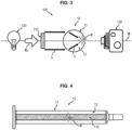
- the operational principle of the inspection system 100 is described with reference to Figure 3 .
- the light source 120, the mask 110, the transparent cylinder under inspection, for example a syringe 10, and the acquisition means 130 are aligned on the inspection axis B, the syringe 10 being placed between the mask 110 and the acquisition means 130.
- the syringe may be supported by a holder (not shown) or handheld by an operator.
- the light source 120 is switched on, a portion of the emitted light EL is blocked by the mask 110 and only the peripheral light L passing around the mask 110 thus reaches the syringe barrel 11. Because of the cylindrical shape of the syringe barrel 11, the light is refracted to illuminate particles and for instance, a particle P.
- the illuminated particle P is easily detectable on an image acquired by the acquisition means 130, thanks to the black mask that acts as a black background.
- a rotation of the syringe 10 around its longitudinal axis A or a rotation of the light source, the mask and the acquisition means around the longitudinal axis A of the syringe 10 is preferable in order to inspect the whole circumference of the syringe 10.
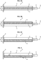
- the width and the positioning of the mask 110 with regard to the light source 120 and the syringe 10 must be chosen in order to block the illumination of 20 to 80 % of the diameter of the syringe 10. Preferably, 30 to 70 % of the diameter of the syringe 10 are not illuminated, more preferably 50 %, as shown in Figure 4 .
- the dimensions and the positioning of the mask 110 with regard to the light source 120 and the syringe 10 may thus be selected for each specific inspection device according to the size of the transparent cylinders to be inspected. In the same way, the arrangement of the mask 110, the transparent cylinder 10, the light source 120 and the acquisition means 130 into the inspection system 100 may be optimized to obtain an acquired image as the one shown in Figure 4 .
- the mask 110 is preferentially a plain plate, and as such, configured to block incoming light over the entirety of its exposed surface that receives light from the light source.
- Figures 5A-5C show different positioning of the mask 110 with respect to the syringe 10, as viewed by the acquisition means 130.
- the mask is centered relative to the longitudinal axis A of the syringe 10. This prevents illumination of a central portion of the syringe and this specific configuration is optimal for the detection of glass particles, which are particularly visible in the middle of the transparent barrel 11.
- the mask 110 is decentered radially relative to the longitudinal axis A of the syringe 10 and only covers half of the diameter D, above or below the longitudinal axis A. This position prevents illumination on a half of the diameter D of the longitudinal barrel 11 and allows the detection of both scratches and particles as it will be explained below.
- the mask 110 has the same length as the barrel 11, which allows inspection of the whole barrel length. However, specific applications may require a mask covering only a partial length of the syringe 10.
- the mask 110 is preferably positioned parallel to the syringe axis A, although a small deviation may be acceptable.
- the mask 110 is preferably opaque to the light emitted by the light source and black-colored in order to provide the greatest possible contrast with particles P. It may be made from any suitable materials such as metal, plastic, paper or cardboard.
- the syringe 10 is illuminated on only a limited portion of its diameter D, the mask 110 both blocking part of the light from the light source 120 and acting as a dark background for the detection of illuminated particles.
- the inspection system 100 therefore provides a simple and reliable way to detect small size particles, for example particles above 300 ⁇ m.
- the configurations of the inspection system as shown in Figures 5B and 5C also allow the detection of scratches. Indeed, if the particles remain visible by contrast with the mask 110, the scratches are easily visible under direct illumination, in the portion where the light is not masked by the mask 110. This case is illustrated in Figure 6 where the acquisition means 130 are able to detect simultaneously both a scratch S in the "white” illuminated region and a particle P in the "black” non-illuminated region.
- the light source 120 may be any light source producing a homogeneous light.
- the light is a white color light that may be obtained for example with LEDs, halogen bulbs or neon tubes.
- the acquired pictures may be processed with commercially available software designed to identify particles and scratches. Such software may also measure the size of the detected defects and help to reject cylindrical containers having unacceptable defects with respect to the targeted quality level.
- a portable inspection system 200 comprises a light source 220 and an integrated mask 210.
- the inspection system 200 is further provided with a switch button 201 and integrated batteries (not shown).
- this portable inspection system 200 may be used manually by an operator for random manual inspections on a manufacturing line.
- a syringe 10 may be positioned by the operator at the right distance from the inspection device 200 in order to obtain an image as the ones shown in Figures 4 or 6 .
- the syringe 10 may also be rotated appropriately by the operator to inspect the whole barrel circumference.
- an inspection system 300 is set up to inspect syringes 10 on an in-line manufacturing process.
- Syringes 10 are carried on a transportation system 30 comprising holders such as plugs 31 able to maintain the syringes in a vertical positioning.
- the inspection system 300 comprises a rotatable axis 301 and a horizontal frame 302.
- the mask 310, the light source 320 and the acquisition means 330 are held by the horizontal frame 302 and aligned on the inspection axis B.
- the light source 320 When a syringe 10 is presented to the inspection system 300, the light source 320 is switched on and the rotatable axis 301 is motorized by an electric motor (not shown) in order to rotate the mask 310, the light source 320 and the acquisition means 330 around the longitudinal axis of the syringe 10.
- a set of pictures is acquired by the acquisition means 330 to inspect the whole circumference of the syringe barrel 11 in a very short period of time without removing the inspected syringe from the in-line manufacturing process.
- the optimal rotating speed depends on the size of the syringe itself, the size of the defects to be detected as well as the quality and the parameters of the acquisition means.
- 60 images with a 13 MPx camera may be captured in 10 to 20 seconds.
- a casing (not shown) may be provided around the inspection system 300, to prevent or limit light coming from other sources that may reduce the efficiency of the light source 320, the casing thus enhancing the contrast and the detection quality of the inspection device 300.
- an inspection system 400 is set-up for the automated inspection of a syringe 10.
- This inspection system 400 is provided with a frame 401 supporting a mask 410, a light source 420 and acquisition means 430.
- the syringe 10 is accommodated on a rotary holder 402 comprising two axes (not shown) provided with three wheels (only two are visible in Figure 9 , the third wheel being hidden by one the two visible wheels). At least one of the two axes is coupled to an electric motor (not shown) in order to maintain the syringe 10 in rotation, the second axis being either motorized or free to rotate.
- This rotary holder 402 allows the full rotation of the syringe 10 in order to inspect the whole circumference of the syringe barrel 11.
- the inspection 430 means may be either a video camera similar to the inspection means 330 or a magnifying glass for a direct visual inspection.
- the inspection system 400 according to this embodiment is especially adapted for an in-depth inspection of high quality syringes or transparent cylinders before their delivery to customers that will proceed to filling with medical products.
Landscapes
- Physics & Mathematics (AREA)
- Health & Medical Sciences (AREA)
- Life Sciences & Earth Sciences (AREA)
- Chemical & Material Sciences (AREA)
- Analytical Chemistry (AREA)
- Biochemistry (AREA)
- General Health & Medical Sciences (AREA)
- General Physics & Mathematics (AREA)
- Immunology (AREA)
- Pathology (AREA)
- Investigating Materials By The Use Of Optical Means Adapted For Particular Applications (AREA)
- Length Measuring Devices By Optical Means (AREA)
Abstract
- a light source (220) able to illuminate a transparent cylinder (10),
- a mask (210) able to block at least part of the light coming from the light source,
the light source (220) and the mask (210) being arranged such that, when the transparent cylinder (10) is positioned in the system for inspection, the light source, the mask and the transparent cylinder are substantially aligned along an inspection axis (B) perpendicular to the longitudinal axis (A) of said transparent cylinder and the mask (210) is interposed between the light source (220) and the transparent cylinder (10) so as to prevent illumination of a first portion of the transparent cylinder having a width smaller than the diameter (D) of the transparent cylinder while allowing illumination of a second portion of the transparent cylinder, the mask being configured to provide a contrast with a particle present in the first portion of the transparent cylinder and illuminated by light refracted by the second portion of the transparent cylinder.
Description
- The invention relates to an inspection system for a transparent cylinder, such as a cylinder made of transparent material and having a longitudinal axis and a diameter. In particular, the inspection system is adapted to detect particles or defects inside transparent cylinders. The invention further relates to a method for detection of particles and defects inside transparent cylinder.
- Transparent cylinders are widespread in various fields such as laboratory glassware in the form of beaker or metering cylinder, food container in the form of tub or bottle or medical glassware in the form of vial, cartridge or syringe. Whatever the field considered, these different containers require a high degree of quality and cleanliness, especially in the medical field where quality and/or cleanliness issues may have a direct impact on the safety of patients and medical staff.
- Indeed, transparent cylinders, made of glass or plastic, are produced by complex manufacturing processes that may result in the formation of particles or defects in the material itself or on its surface. A careful inspection step of such transparent cylinders is thus required before delivery to the customer.
- Such an inspection step is usually made automatically by cameras using a back end light positioned behind the transparent cylinder. However, this kind of inspection does not allow the detection of small-size cosmetic defects and/or glass particles. Furthermore, such an inspection system is not specific as it cannot differentiate the different types of observed defects.
- There is therefore a need for a reliable system able to detect small glass particles and cosmetic defects.
- A goal of the present invention is to propose an improved inspection system able to detect small-sized glass particles and defects. Another goal of the present invention is to provide an inspection system able to discriminate the different types of defects.
- An object of the present invention is a portable inspection system for detecting a particle in a transparent cylinder, the transparent cylinder having a longitudinal axis and a diameter, the inspection system being configured to be held by an operator and comprising:
- a light source able to illuminate a transparent cylinder,
- a mask able to block at least part of the light coming from the light source,
- The expression "substantially aligned" means that the light source, the mask and the acquisition means are aligned on the inspection axis, although a small deviation is acceptable. The specific set-up of the inspection system according to the present invention can be easily realized by a skilled person in the art by checking the image acquired by the acquisition means.
- All kind of transparent cylinders can be inspected with the inspection system of the present invention, such as laboratory glassware, food containers or medical glass wares. Examples of such cylinders are beakers, metering cylinders, bottles, jars, medical vial, cartridges or syringes. Any other cylinders may be inspected as long as they are made of a transparent material. Thanks to the partial illumination of the transparent cylinder, any particle inside the non-illuminated part of the transparent cylinder is illuminated by an indirect light refracted by the illuminated portion of the transparent cylinder and is clearly visible in front of the mask acting as a dark background. Such illuminated particles may be easily detected by the acquisition means such as a human eye or a video camera.
- The mask may be arrange such that the width of the non-illuminated portion of the transparent cylinder may range from 20 to 80% of the diameter of the transparent cylinder, . or is equal to 50% of the diameter of the transparent cylinder. In some configurations, the mask is arranged such that the non-illuminated portion of the transparent cylinder is a central portion of the transparent cylinder.
- This configuration of the inspection system is especially adapted to detect glass particles at the surface of the transparent cylinder or inside the transparent cylinder itself. In other configurations, the mask is arranged such that the non-illuminated portion of the transparent cylinder extends on a side of the transparent cylinder.
- According to the configuration of the inspection system, particles may be detected or both particles and scratches during a single inspection step. Such an inspection system is thus able to differentiate a particle from a scratch which allows an accurate inspection of transparent cylinders.
- In embodiments, the mask is opaque to the light emitted by the light source and preferably black-colored. This allows for an optimized contrast to detect easily particles above 300 µm.
- The light source is preferably able to generate a white light. LEDs, halogen bulbs or neon tube may be used.
- The inspection system may further comprise a switch button provided on the portable inspection device for controlling illumination of the light source.
- The light source may be battery powered.
- Another object of the present invention is a method to inspect a transparent cylinder having a longitudinal axis and a diameter for detecting a particle, comprising:
- providing a portable inspection system comprising a light source able to illuminate the transparent cylinder, and a mask able to block at least part of the light coming from the light source,
- aligning the light source, the mask and the transparent cylinder on an inspection axis, such that the longitudinal axis is perpendicular to the inspection axis and that the mask prevents illumination of a first portion of the transparent cylinder having a width smaller than the diameter of the transparent cylinder while allowing illumination of a second portion of the transparent cylinder, and
- obtaining an image of the transparent cylinder from a point of view opposite to the mask by a contrast provided by the mask with a particle present in the first portion of the transparent cylinder and illuminated by light refracted by the second portion of the transparent cylinder.
- In embodiments, the method to inspect a transparent cylinder further comprises a rotation of the transparent cylinder around its longitudinal axis with regard to the mask and the light source.
- In embodiments, the method to inspect a transparent cylinder further comprises a rotation of the mask and the light source around the longitudinal axis of the transparent cylinder.
- Both rotations allow a fast and comprehensive inspection of the transparent cylinder.
-
-
Figure 1 shows a syringe as an example of a transparent cylinder to be inspected with an inspection system. -
Figure 2 is a schematic graph of an inspection system. -
Figure 3 shows the operating principle of an inspection system according toFigure 2 . -
Figure 4 shows a particle as detected by the inspection system according toFigure 2 . -
Figures 5A-5C show different possible positions of the mask of the inspection system according toFigure 2 as regards as a syringe according toFigure 1 . -
Figure 6 shows a particle and a scratch as detected with the mask as positioned inFigure 5C . -
Figure 7 shows a first embodiment according to the present invention of an inspection system according toFigure 2 . -
Figure 8 shows a second embodiment which is not part of the present invention of an inspection system according toFigure 2 . -
Figure 9 shows a third embodiment which is not part of the present invention of an inspection system according toFigure 2 . -
Figure 1 shows asyringe 10 as an example of a transparent cylinder that can be inspected by a system according to the present invention. Others examples of transparent cylinders include cartridges, vials as well as bottles and glassware such as glasses, beakers or metering cylinders (not shown). Thesyringe 10 ofFigure 1 includes a cylindricaltransparent barrel 11 having a diameter D, a longitudinal axis A and defining atubular chamber 12 with two extremities. One of the extremities of thesyringe 10 corresponds to atip 13 used for the injection of medical products and that may be provided with a staked needle or an adaptor for connecting an intravenous line or any other types of connectors. The other extremity of the cylindricaltransparent barrel 11 corresponds to aflange 14 used for gripping thesyringe 10. Thesyringe 10 may be made from any transparent material such as glass or plastic, for example polyethylene, polypropylene, polycarbonate or cyclic polyolefin and any combination thereof. - In
Figure 2 , aschematic inspection system 100 comprises ablack mask 110, alight source 120 and acquisition means 130. Themask 110, thelight source 120 and the acquisition means 130 are aligned on an axis B, hereinafter called inspection axis. To perform an inspection, thesyringe 10 is placed between themask 110 and the acquisition means 130 so that its longitudinal axis A is perpendicular to the axis B. The acquisition means 130 may be any acquisition means capable of obtaining an image of the cylinder, for example the eye of an operator or a video camera. - The operational principle of the
inspection system 100 is described with reference toFigure 3 . As already mentioned, thelight source 120, themask 110, the transparent cylinder under inspection, for example asyringe 10, and the acquisition means 130 are aligned on the inspection axis B, thesyringe 10 being placed between themask 110 and the acquisition means 130. To that end, the syringe may be supported by a holder (not shown) or handheld by an operator. When thelight source 120 is switched on, a portion of the emitted light EL is blocked by themask 110 and only the peripheral light L passing around themask 110 thus reaches thesyringe barrel 11. Because of the cylindrical shape of thesyringe barrel 11, the light is refracted to illuminate particles and for instance, a particle P. As shown inFigure 4 , which shows the syringe and mask from the point of view of the acquisition means, the illuminated particle P is easily detectable on an image acquired by the acquisition means 130, thanks to the black mask that acts as a black background. A rotation of thesyringe 10 around its longitudinal axis A or a rotation of the light source, the mask and the acquisition means around the longitudinal axis A of thesyringe 10 is preferable in order to inspect the whole circumference of thesyringe 10. - The width and the positioning of the
mask 110 with regard to thelight source 120 and thesyringe 10 must be chosen in order to block the illumination of 20 to 80 % of the diameter of thesyringe 10. Preferably, 30 to 70 % of the diameter of thesyringe 10 are not illuminated, more preferably 50 %, as shown inFigure 4 . The dimensions and the positioning of themask 110 with regard to thelight source 120 and thesyringe 10 may thus be selected for each specific inspection device according to the size of the transparent cylinders to be inspected. In the same way, the arrangement of themask 110, thetransparent cylinder 10, thelight source 120 and the acquisition means 130 into theinspection system 100 may be optimized to obtain an acquired image as the one shown inFigure 4 . - Moreover, the
mask 110 is preferentially a plain plate, and as such, configured to block incoming light over the entirety of its exposed surface that receives light from the light source. - In addition,
Figures 5A-5C show different positioning of themask 110 with respect to thesyringe 10, as viewed by the acquisition means 130. InFigures 4 and5A , the mask is centered relative to the longitudinal axis A of thesyringe 10. This prevents illumination of a central portion of the syringe and this specific configuration is optimal for the detection of glass particles, which are particularly visible in the middle of thetransparent barrel 11. InFigures 5B and 5C , themask 110 is decentered radially relative to the longitudinal axis A of thesyringe 10 and only covers half of the diameter D, above or below the longitudinal axis A. This position prevents illumination on a half of the diameter D of thelongitudinal barrel 11 and allows the detection of both scratches and particles as it will be explained below. - In
Figures 5A-5C , themask 110 has the same length as thebarrel 11, which allows inspection of the whole barrel length. However, specific applications may require a mask covering only a partial length of thesyringe 10. - Furthermore, the
mask 110 is preferably positioned parallel to the syringe axis A, although a small deviation may be acceptable. - Finally, the
mask 110 is preferably opaque to the light emitted by the light source and black-colored in order to provide the greatest possible contrast with particles P. It may be made from any suitable materials such as metal, plastic, paper or cardboard. - Thanks to the
mask 110, thesyringe 10 is illuminated on only a limited portion of its diameter D, themask 110 both blocking part of the light from thelight source 120 and acting as a dark background for the detection of illuminated particles. Theinspection system 100 therefore provides a simple and reliable way to detect small size particles, for example particles above 300 µm. - In addition to the detection of particles, the configurations of the inspection system as shown in
Figures 5B and 5C also allow the detection of scratches. Indeed, if the particles remain visible by contrast with themask 110, the scratches are easily visible under direct illumination, in the portion where the light is not masked by themask 110. This case is illustrated inFigure 6 where the acquisition means 130 are able to detect simultaneously both a scratch S in the "white" illuminated region and a particle P in the "black" non-illuminated region. - The
light source 120 may be any light source producing a homogeneous light. Preferably, the light is a white color light that may be obtained for example with LEDs, halogen bulbs or neon tubes. - In case the acquisition means comprise a video camera, the acquired pictures may be processed with commercially available software designed to identify particles and scratches. Such software may also measure the size of the detected defects and help to reject cylindrical containers having unacceptable defects with respect to the targeted quality level.
- In a first embodiment of the present invention visible in
Figure 7 , aportable inspection system 200 comprises alight source 220 and anintegrated mask 210. Theinspection system 200 is further provided with aswitch button 201 and integrated batteries (not shown). For example, thisportable inspection system 200 may be used manually by an operator for random manual inspections on a manufacturing line. Asyringe 10 may be positioned by the operator at the right distance from theinspection device 200 in order to obtain an image as the ones shown inFigures 4 or6 . Thesyringe 10 may also be rotated appropriately by the operator to inspect the whole barrel circumference. - In a second embodiment (not part of the present invention) visible in
Figure 8 , aninspection system 300 is set up to inspectsyringes 10 on an in-line manufacturing process.Syringes 10 are carried on atransportation system 30 comprising holders such asplugs 31 able to maintain the syringes in a vertical positioning. Theinspection system 300 comprises arotatable axis 301 and ahorizontal frame 302. Themask 310, thelight source 320 and the acquisition means 330 are held by thehorizontal frame 302 and aligned on the inspection axis B. When asyringe 10 is presented to theinspection system 300, thelight source 320 is switched on and therotatable axis 301 is motorized by an electric motor (not shown) in order to rotate themask 310, thelight source 320 and the acquisition means 330 around the longitudinal axis of thesyringe 10. A set of pictures is acquired by the acquisition means 330 to inspect the whole circumference of thesyringe barrel 11 in a very short period of time without removing the inspected syringe from the in-line manufacturing process. The optimal rotating speed depends on the size of the syringe itself, the size of the defects to be detected as well as the quality and the parameters of the acquisition means. For example, 60 images with a 13 MPx camera may be captured in 10 to 20 seconds. A casing (not shown) may be provided around theinspection system 300, to prevent or limit light coming from other sources that may reduce the efficiency of thelight source 320, the casing thus enhancing the contrast and the detection quality of theinspection device 300. - In a third embodiment (not part of the present invention) disclosed in
Figure 9 , aninspection system 400 is set-up for the automated inspection of asyringe 10. Thisinspection system 400 is provided with aframe 401 supporting amask 410, alight source 420 and acquisition means 430. Thesyringe 10 is accommodated on arotary holder 402 comprising two axes (not shown) provided with three wheels (only two are visible inFigure 9 , the third wheel being hidden by one the two visible wheels). At least one of the two axes is coupled to an electric motor (not shown) in order to maintain thesyringe 10 in rotation, the second axis being either motorized or free to rotate. Thisrotary holder 402 allows the full rotation of thesyringe 10 in order to inspect the whole circumference of thesyringe barrel 11. Theinspection 430 means may be either a video camera similar to the inspection means 330 or a magnifying glass for a direct visual inspection. Theinspection system 400 according to this embodiment is especially adapted for an in-depth inspection of high quality syringes or transparent cylinders before their delivery to customers that will proceed to filling with medical products. - As applicable, all individual features that are shown in the individual embodiments can be combined and/or exchanged with each other without departing from the scope of the invention.
Claims (13)
- Portable inspection system (200) for detecting a particle in a transparent cylinder (10) having a longitudinal axis (A) and a diameter (D), the inspection system being configured to be held by an operator and comprising:- a light source (220) able to illuminate a transparent cylinder (10), and- a mask (210) able to block at least part of the light coming from the light source,the light source (220) and the mask (210) being arranged such that, when the transparent cylinder (10) is positioned in the system for inspection, the light source, the mask and the transparent cylinder are substantially aligned along an inspection axis (B) perpendicular to the longitudinal axis (A) of said transparent cylinder and the mask (210) is interposed between the light source (220) and the transparent cylinder (10) so as to prevent illumination of a first portion of the transparent cylinder having a width smaller than the diameter (D) of the transparent cylinder while allowing illumination of a second portion of the transparent cylinder, the mask being configured to provide a contrast with a particle present in the first portion of the transparent cylinder and illuminated by light refracted by the second portion of the transparent cylinder.
- Portable inspection system (200) according to claim 1, wherein the mask (210) is arranged such that the width of the non-illuminated portion of the transparent cylinder ranges from 20 to 80 % of the diameter (D) of the transparent cylinder (10).
- Portable inspection system (200) according to claim 1 or claim 2, wherein the mask (210) is arranged such that the width of the non-illuminated portion of the transparent cylinder is equal to 50% of the diameter (D) of the transparent cylinder (10).
- Portable inspection system according to any of the previous claims, wherein the mask is arranged such that the non-illuminated portion of the transparent cylinder is a central portion of the transparent cylinder (10).
- Portable inspection system according to any of claims 1 to 3, wherein the mask is arranged such that the non-illuminated portion of the transparent cylinder extends on a side of the transparent cylinder (10).
- Portable inspection system (200) according to any of the previous claims, wherein the mask (110) is opaque to the light emitted by the light source.
- Portable inspection system (200) according to any of the previous claim, wherein the mask (210) is black-colored.
- Portable inspection system (200) according to any of the previous claims, wherein the light source (220) is able to generate a white light.
- Portable inspection system according to any of the previous claims, further comprising a switch button provided on the portable inspection device for controlling illumination of the light source.
- Portable inspection system according to any of the previous claims, wherein the light source is battery powered.
- Method to inspect a transparent cylinder (10) having a longitudinal axis (A) and a diameter (D) for detecting a particle, comprising:• providing a portable inspection system (200) comprising a light source (220) able to illuminate the transparent cylinder, and a mask (210) able to block at least part of the light coming from the light source (220),• aligning the light source (220), the mask (210) and the transparent cylinder (10) on an inspection axis (B), such that the longitudinal axis (A) is perpendicular to the inspection axis (B) and that the mask prevents illumination of a first portion of the transparent cylinder having a width smaller than the diameter (D) of the transparent cylinder while allowing illumination of a second portion of the transparent cylinder,• obtaining an image of the transparent cylinder from a point of view opposite to the mask by a contrast provided by the mask with a particle present in the first portion of the transparent cylinder and illuminated by light refracted by the second portion of the transparent cylinder.
- Method to inspect a transparent cylinder according to claim 11, further comprising a rotation of the transparent cylinder (10) around its longitudinal axis (A) with regard to the mask (210) and the light source (220).
- Method to inspect a transparent cylinder according to claim 11, further comprising a rotation of the mask (210) and the light source (220) around the longitudinal axis of the transparent cylinder (10).
Applications Claiming Priority (3)
| Application Number | Priority Date | Filing Date | Title |
|---|---|---|---|
| EP16305214 | 2016-02-24 | ||
| PCT/EP2017/054269 WO2017144634A1 (en) | 2016-02-24 | 2017-02-24 | System and method for inspecting a transparent cylinder |
| EP17707522.3A EP3420346B1 (en) | 2016-02-24 | 2017-02-24 | System and method for inspecting a transparent cylinder |
Related Parent Applications (2)
| Application Number | Title | Priority Date | Filing Date |
|---|---|---|---|
| EP17707522.3A Division-Into EP3420346B1 (en) | 2016-02-24 | 2017-02-24 | System and method for inspecting a transparent cylinder |
| EP17707522.3A Division EP3420346B1 (en) | 2016-02-24 | 2017-02-24 | System and method for inspecting a transparent cylinder |
Publications (2)
| Publication Number | Publication Date |
|---|---|
| EP4502580A2 true EP4502580A2 (en) | 2025-02-05 |
| EP4502580A3 EP4502580A3 (en) | 2025-04-30 |
Family
ID=55443212
Family Applications (2)
| Application Number | Title | Priority Date | Filing Date |
|---|---|---|---|
| EP24221889.9A Pending EP4502580A3 (en) | 2016-02-24 | 2017-02-24 | System and method for inspecting a transparent cylinder |
| EP17707522.3A Active EP3420346B1 (en) | 2016-02-24 | 2017-02-24 | System and method for inspecting a transparent cylinder |
Family Applications After (1)
| Application Number | Title | Priority Date | Filing Date |
|---|---|---|---|
| EP17707522.3A Active EP3420346B1 (en) | 2016-02-24 | 2017-02-24 | System and method for inspecting a transparent cylinder |
Country Status (7)
| Country | Link |
|---|---|
| US (2) | US10663409B2 (en) |
| EP (2) | EP4502580A3 (en) |
| JP (1) | JP7046819B2 (en) |
| CN (3) | CN112881433A (en) |
| ES (1) | ES3017687T3 (en) |
| MX (2) | MX385958B (en) |
| WO (1) | WO2017144634A1 (en) |
Families Citing this family (7)
| Publication number | Priority date | Publication date | Assignee | Title |
|---|---|---|---|---|
| JP7046819B2 (en) * | 2016-02-24 | 2022-04-04 | ベクトン ディキンソン フランス | Systems and methods for inspecting transparent cylinders |
| FR3101947B1 (en) * | 2019-10-15 | 2023-11-24 | Cie Plastic Omnium Se | Device and method for evaluating the quality of a coating |
| EP3916379B1 (en) * | 2020-05-29 | 2025-04-09 | Becton Dickinson France | Method for inspecting a medical container and system used therefor |
| US12608789B2 (en) * | 2021-02-15 | 2026-04-21 | Amgen Inc. | Systems and methods for automated in-line plunger depth measurement |
| IL319423A (en) * | 2022-09-09 | 2025-05-01 | Hoffmann La Roche | Inspection system and method for a closed medical container |
| IT202200026136A1 (en) * | 2022-12-20 | 2024-06-20 | Gd Spa | ARTICLE INSPECTION SYSTEM |
| TWI903669B (en) * | 2024-08-05 | 2025-11-01 | 可成應材科技有限公司 | Dust inspection device |
Family Cites Families (51)
| Publication number | Priority date | Publication date | Assignee | Title |
|---|---|---|---|---|
| US3880501A (en) * | 1973-04-16 | 1975-04-29 | Tropel | Optical system for objective refractor for the eye |
| JPS5927859B2 (en) * | 1978-07-26 | 1984-07-09 | 石塚硝子株式会社 | Glass bottle body defect inspection device |
| JPH0612344B2 (en) * | 1982-08-31 | 1994-02-16 | サントリー株式会社 | Inspection device for scuffing bottles |
| US4609991A (en) * | 1983-07-19 | 1986-09-02 | The United States Of America As Represented By The Department Of Health And Human Services | Automated system for determining the molecular weight and/or concentration of macromolecules via sedimentation equilibrium |
| US4610542A (en) * | 1984-11-16 | 1986-09-09 | Owens-Illinois, Inc. | System for detecting selective refractive defects in transparent articles |
| JPS61207952A (en) * | 1985-03-12 | 1986-09-16 | Hajime Sangyo Kk | Defect inspecting device for bottle made of transparent material |
| JPS61232195A (en) * | 1985-03-29 | 1986-10-16 | サッポロビール株式会社 | Cap inspection device for bottle mouth |
| CN1008003B (en) * | 1985-04-01 | 1990-05-16 | 欧文斯-伊利诺衣公司 | System for detecting selective refractive defects in transparent articles |
| DE3880700D1 (en) * | 1987-02-04 | 1993-06-09 | Hoefliger Harro Verpackung | METHOD AND DEVICE FOR DETECTING FOREIGN BODIES IN FLUIDS. |
| US4868404A (en) * | 1987-04-23 | 1989-09-19 | Hajime Industries, Ltd. | Surface inspection apparatus using a mask system to monitor uneven surfaces |
| JPH01141341A (en) * | 1987-11-27 | 1989-06-02 | Hajime Sangyo Kk | Bottle bottom inspection instrument |
| JPH0627717B2 (en) * | 1988-04-13 | 1994-04-13 | 株式会社キリンテクノシステム | Bottle body inspection device |
| EP0344617B1 (en) * | 1988-05-30 | 1995-08-02 | Kabushiki Kaisha Kirin Techno System | Method and apparatus for inspecting sidewalls of bottles |
| JPH0731135B2 (en) * | 1989-11-22 | 1995-04-10 | 東洋ガラス株式会社 | Defect detection device for bottle body |
| US5215883A (en) * | 1990-07-09 | 1993-06-01 | The Research Foundation | Electrophoretic mobility of fluorophore labeled particles in gels by fluorophore movement after photobleaching |
| JPH06100555B2 (en) * | 1990-12-19 | 1994-12-12 | 東洋ガラス株式会社 | Defect inspection method and device for transparent object |
| JPH0711490B2 (en) * | 1992-02-12 | 1995-02-08 | 東洋ガラス株式会社 | Defect detection method and device for transparent object |
| IL100972A0 (en) * | 1992-02-17 | 1992-11-15 | Optomic Techn Corp Ltd | Device for testing optical elements |
| US5243400A (en) * | 1992-04-27 | 1993-09-07 | Owens-Brockway Glass Container Inc. | Inspection of transparent containers |
| JPH06249969A (en) * | 1993-02-26 | 1994-09-09 | Omron Corp | Photoelectric switch and photoelectric switch detection method |
| JPH0929184A (en) * | 1995-07-18 | 1997-02-04 | Ishikawajima Harima Heavy Ind Co Ltd | Glass bottle color identification device |
| US5859375A (en) * | 1996-04-03 | 1999-01-12 | Barringer Research Limited | Apparatus for and method of collecting trace samples for analysis |
| JPH1019799A (en) * | 1996-07-09 | 1998-01-23 | Mutual Corp | Method and apparatus for inspecting foreign matter in container |
| US6034766A (en) * | 1997-03-05 | 2000-03-07 | Asahi Kogaku Kogyo Kabushiki Kaisha | Optical member inspection apparatus |
| DE19741384A1 (en) | 1997-09-19 | 1999-03-25 | Heuft Systemtechnik Gmbh | Method for recognizing random dispersive material, impurities and other faults in transparent objects |
| JP3417816B2 (en) * | 1997-10-22 | 2003-06-16 | ペンタックス株式会社 | Optical member inspection device, image processing device, and computer readable medium |
| EP1006350A1 (en) * | 1998-11-30 | 2000-06-07 | Kirin Techno-System Corporation | Method for detecting defects in bottles |
| JP2001059823A (en) * | 1999-08-25 | 2001-03-06 | Fuji Electric Co Ltd | Visual inspection system |
| DE19948140A1 (en) * | 1999-09-29 | 2001-04-05 | Friedrich Schiller Uni Jena Bu | Method and device for detecting defects in and on transparent objects |
| US7010991B2 (en) * | 2000-09-13 | 2006-03-14 | Pentagon Technologies Group, Inc. | Surface particle detector |
| US6424414B1 (en) * | 2000-10-16 | 2002-07-23 | Agr International, Inc. | Method and apparatus for detecting refractive defects in transparent containers |
| JP3698424B2 (en) | 2001-11-14 | 2005-09-21 | Hoya株式会社 | Glass lump inspection method and inspection apparatus, glass lump molding method, optical element manufacturing method, and glass material for press molding |
| FR2846423B1 (en) * | 2002-10-25 | 2005-12-23 | Bsn Glasspack | METHOD AND DEVICE FOR DETECTING SURFACE DEFECTS PRESENTED BY UNR RING OF A TRANSPARENT OR TRANSLUCENT REVOLUTION CONTAINER |
| US7321679B2 (en) * | 2004-07-02 | 2008-01-22 | Emhart Glass Sa | Machine for inspecting glass bottles |
| JP2006343138A (en) * | 2005-06-07 | 2006-12-21 | Keizo Taishaku | Inspection device |
| CN101297192B (en) * | 2005-09-09 | 2012-05-30 | 萨克米伊莫拉机械合作社合作公司 | Method and device for visually monitoring objects |
| EP1934585B1 (en) * | 2005-10-15 | 2010-04-28 | Udviklingsselskabet Innoscan K/S | Method and system for irradiating and inspecting liquid-carrying containers |
| US20070181822A1 (en) * | 2006-02-06 | 2007-08-09 | Charles Harris Mazel | Method and apparatus for fluorescent magnetic particle and fluorescent liquid penetrant testing |
| DE102006032701B3 (en) * | 2006-07-14 | 2008-01-10 | Sensor Instruments Entwicklungs- Und Vertriebs Gmbh | Laser excited luminescence radiation detection device, has housing formed with sensor opening, which is formed by exciter radiations produced by laser contained in housing for emission and entrance for excited luminescence radiation |
| US20090154789A1 (en) * | 2007-12-17 | 2009-06-18 | Gradience Imaging, Inc. | System and method for detecting optical defects |
| JP4886830B2 (en) * | 2009-10-15 | 2012-02-29 | 東洋ガラス株式会社 | Burn glass inspection method and apparatus for transparent glass container |
| CN201561935U (en) * | 2009-12-22 | 2010-08-25 | 燕京啤酒(桂林漓泉)股份有限公司 | Bottle body film detecting device of bottle inspector |
| JP4668354B1 (en) * | 2010-07-20 | 2011-04-13 | トリオ・セラミックス株式会社 | Transparent tube bubble detection device and bubble detection method |
| DE102010043632B4 (en) * | 2010-11-09 | 2017-08-24 | Krones Aktiengesellschaft | Method for checking the operation of an inspection device and device for inspecting a product flow |
| JP2013130489A (en) | 2011-12-22 | 2013-07-04 | Kirin Techno-System Co Ltd | Illumination device and inspection device of glass bottle |
| FR2993662B1 (en) * | 2012-07-23 | 2015-05-15 | Msc & Sgcc | METHOD AND INSTALLATION FOR THE DETECTION IN PARTICULAR OF REFRACTANT DEFECTS |
| CN103115928A (en) * | 2013-02-05 | 2013-05-22 | 深圳市华星光电技术有限公司 | Device, machine and method for checking foreign substances on surfaces of glass |
| WO2014144624A1 (en) * | 2013-03-15 | 2014-09-18 | NOBLE, Aaron, Matthew | Methods for detecting materials in a body cavity |
| CN103234979B (en) | 2013-04-07 | 2015-09-09 | 北京大恒图像视觉有限公司 | Vial defect detecting device and point picture device |
| GB201601960D0 (en) * | 2016-02-03 | 2016-03-16 | Glaxosmithkline Biolog Sa | Novel device |
| JP7046819B2 (en) * | 2016-02-24 | 2022-04-04 | ベクトン ディキンソン フランス | Systems and methods for inspecting transparent cylinders |
-
2017
- 2017-02-24 JP JP2018544859A patent/JP7046819B2/en active Active
- 2017-02-24 EP EP24221889.9A patent/EP4502580A3/en active Pending
- 2017-02-24 CN CN202110066111.2A patent/CN112881433A/en active Pending
- 2017-02-24 CN CN201720174660.0U patent/CN206583820U/en not_active Withdrawn - After Issue
- 2017-02-24 MX MX2018009909A patent/MX385958B/en unknown
- 2017-02-24 CN CN201710102686.9A patent/CN107121443B/en active Active
- 2017-02-24 WO PCT/EP2017/054269 patent/WO2017144634A1/en not_active Ceased
- 2017-02-24 US US16/078,821 patent/US10663409B2/en active Active
- 2017-02-24 ES ES17707522T patent/ES3017687T3/en active Active
- 2017-02-24 EP EP17707522.3A patent/EP3420346B1/en active Active
-
2018
- 2018-08-15 MX MX2021010741A patent/MX2021010741A/en unknown
-
2020
- 2020-04-06 US US16/841,209 patent/US11125699B2/en active Active
Also Published As
| Publication number | Publication date |
|---|---|
| JP7046819B2 (en) | 2022-04-04 |
| CN107121443A (en) | 2017-09-01 |
| EP3420346B1 (en) | 2025-03-26 |
| US20200232935A1 (en) | 2020-07-23 |
| EP3420346A1 (en) | 2019-01-02 |
| CN112881433A (en) | 2021-06-01 |
| WO2017144634A1 (en) | 2017-08-31 |
| ES3017687T3 (en) | 2025-05-13 |
| EP4502580A3 (en) | 2025-04-30 |
| MX385958B (en) | 2025-03-18 |
| CN206583820U (en) | 2017-10-24 |
| MX2018009909A (en) | 2018-09-11 |
| US10663409B2 (en) | 2020-05-26 |
| EP3420346C0 (en) | 2025-03-26 |
| MX2021010741A (en) | 2021-10-14 |
| US11125699B2 (en) | 2021-09-21 |
| JP2019506616A (en) | 2019-03-07 |
| US20190056335A1 (en) | 2019-02-21 |
| CN107121443B (en) | 2021-02-12 |
Similar Documents
| Publication | Publication Date | Title |
|---|---|---|
| US11125699B2 (en) | System and method for inspecting a transparent cylinder | |
| ES2714719T3 (en) | Kit and method of inspecting an item | |
| EP3262400B1 (en) | Device and method for testing and inspecting integrity of a container | |
| US7697132B2 (en) | Machine for inspecting glass containers | |
| US20190049390A1 (en) | Novel Device | |
| US11841327B2 (en) | Detection and characterization of defects in pharmaceutical cylindrical containers | |
| CN102661955A (en) | Detection system of visible foreign matters | |
| US20200072736A1 (en) | IR Probe for Detection of Contaminants in Sealed Containers | |
| Hindelang et al. | Forensic investigation in the pharmaceutical industry: identification procedure of visible particles in (drug) solutions and different containers by combining vibrational and X-ray spectroscopic techniques | |
| US11703451B2 (en) | Apparatus and method for inspecting transparent cylindrical containers containing milky products, in particular for medical applications | |
| EP4291878B1 (en) | Method for monitoring the compliance of a container and apparatus thereof | |
| EP3485429A1 (en) | Method of tracking and tracing syringes in the pharmaceutical industry | |
| CN202720199U (en) | Detecting and observing device for visible foreign body detection system | |
| US20080273197A1 (en) | Machine for inspecting glass containers | |
| EP3887808A1 (en) | Vial inspection method and apparatus | |
| EP4639153A1 (en) | System for inspecting an article | |
| CA2837037A1 (en) | Inspection device and method for a single-dose casing for a substantially transparent container for a substantially transparent liquid |
Legal Events
| Date | Code | Title | Description |
|---|---|---|---|
| PUAI | Public reference made under article 153(3) epc to a published international application that has entered the european phase |
Free format text: ORIGINAL CODE: 0009012 |
|
| STAA | Information on the status of an ep patent application or granted ep patent |
Free format text: STATUS: THE APPLICATION HAS BEEN PUBLISHED |
|
| AC | Divisional application: reference to earlier application |
Ref document number: 3420346 Country of ref document: EP Kind code of ref document: P |
|
| AK | Designated contracting states |
Kind code of ref document: A2 Designated state(s): AL AT BE BG CH CY CZ DE DK EE ES FI FR GB GR HR HU IE IS IT LI LT LU LV MC MK MT NL NO PL PT RO RS SE SI SK SM TR |
|
| REG | Reference to a national code |
Ref country code: DE Ref legal event code: R079 Free format text: PREVIOUS MAIN CLASS: G01N0021880000 Ipc: G01N0021958000 |
|
| PUAL | Search report despatched |
Free format text: ORIGINAL CODE: 0009013 |
|
| AK | Designated contracting states |
Kind code of ref document: A3 Designated state(s): AL AT BE BG CH CY CZ DE DK EE ES FI FR GB GR HR HU IE IS IT LI LT LU LV MC MK MT NL NO PL PT RO RS SE SI SK SM TR |
|
| RIC1 | Information provided on ipc code assigned before grant |
Ipc: F21L 4/00 20060101ALI20250325BHEP Ipc: F21V 14/00 20180101ALI20250325BHEP Ipc: F21V 11/04 20060101ALI20250325BHEP Ipc: G01N 21/88 20060101ALI20250325BHEP Ipc: G01N 21/90 20060101ALI20250325BHEP Ipc: G01N 21/958 20060101AFI20250325BHEP |
|
| STAA | Information on the status of an ep patent application or granted ep patent |
Free format text: STATUS: REQUEST FOR EXAMINATION WAS MADE |
|
| 17P | Request for examination filed |
Effective date: 20250729 |
|
| GRAP | Despatch of communication of intention to grant a patent |
Free format text: ORIGINAL CODE: EPIDOSNIGR1 |
|
| STAA | Information on the status of an ep patent application or granted ep patent |
Free format text: STATUS: GRANT OF PATENT IS INTENDED |
|
| GRAS | Grant fee paid |
Free format text: ORIGINAL CODE: EPIDOSNIGR3 |
|
| INTG | Intention to grant announced |
Effective date: 20260401 |
|
| GRAA | (expected) grant |
Free format text: ORIGINAL CODE: 0009210 |
|
| STAA | Information on the status of an ep patent application or granted ep patent |
Free format text: STATUS: THE PATENT HAS BEEN GRANTED |