EP4502521A1 - Plate heat exchanger - Google Patents
Plate heat exchanger Download PDFInfo
- Publication number
- EP4502521A1 EP4502521A1 EP23773564.2A EP23773564A EP4502521A1 EP 4502521 A1 EP4502521 A1 EP 4502521A1 EP 23773564 A EP23773564 A EP 23773564A EP 4502521 A1 EP4502521 A1 EP 4502521A1
- Authority
- EP
- European Patent Office
- Prior art keywords
- heat exchange
- heat
- heat transfer
- exchange spaces
- transfer medium
- Prior art date
- Legal status (The legal status is an assumption and is not a legal conclusion. Google has not performed a legal analysis and makes no representation as to the accuracy of the status listed.)
- Pending
Links
Images





Classifications
-
- F—MECHANICAL ENGINEERING; LIGHTING; HEATING; WEAPONS; BLASTING
- F28—HEAT EXCHANGE IN GENERAL
- F28D—HEAT-EXCHANGE APPARATUS, NOT PROVIDED FOR IN ANOTHER SUBCLASS, IN WHICH THE HEAT-EXCHANGE MEDIA DO NOT COME INTO DIRECT CONTACT
- F28D9/00—Heat-exchange apparatus having stationary plate-like or laminated conduit assemblies for both heat-exchange media, the media being in contact with different sides of a conduit wall
- F28D9/0062—Heat-exchange apparatus having stationary plate-like or laminated conduit assemblies for both heat-exchange media, the media being in contact with different sides of a conduit wall the conduits for one heat-exchange medium being formed by spaced plates with inserted elements
- F28D9/0075—Heat-exchange apparatus having stationary plate-like or laminated conduit assemblies for both heat-exchange media, the media being in contact with different sides of a conduit wall the conduits for one heat-exchange medium being formed by spaced plates with inserted elements the plates having openings therein for circulation of the heat-exchange medium from one conduit to another
-
- F—MECHANICAL ENGINEERING; LIGHTING; HEATING; WEAPONS; BLASTING
- F28—HEAT EXCHANGE IN GENERAL
- F28D—HEAT-EXCHANGE APPARATUS, NOT PROVIDED FOR IN ANOTHER SUBCLASS, IN WHICH THE HEAT-EXCHANGE MEDIA DO NOT COME INTO DIRECT CONTACT
- F28D9/00—Heat-exchange apparatus having stationary plate-like or laminated conduit assemblies for both heat-exchange media, the media being in contact with different sides of a conduit wall
- F28D9/0093—Multi-circuit heat-exchangers, e.g. integrating different heat exchange sections in the same unit or heat-exchangers for more than two fluids
-
- F—MECHANICAL ENGINEERING; LIGHTING; HEATING; WEAPONS; BLASTING
- F28—HEAT EXCHANGE IN GENERAL
- F28F—DETAILS OF HEAT-EXCHANGE AND HEAT-TRANSFER APPARATUS, OF GENERAL APPLICATION
- F28F3/00—Plate-like or laminated elements; Assemblies of plate-like or laminated elements
- F28F3/08—Elements constructed for building-up into stacks, e.g. capable of being taken apart for cleaning
- F28F3/10—Arrangements for sealing the margins
Definitions
- the embodiments of the present invention relate to a plate heat exchanger.
- a conventional plate heat exchanger 100' includes a plurality of heat transfer plates 10, and heat exchange spaces formed between adjacent heat transfer plates 10 of the plurality of heat transfer plates 10, the heat exchange spaces including a plurality of first heat exchange spaces 20A for a first heat transfer medium, a plurality of second heat exchange spaces 20B for a second heat transfer medium, and a plurality of third heat exchange spaces 20C for a third heat transfer medium, and each of the plurality of first heat exchange spaces 20A and the plurality of second heat exchange spaces 20B being adjacent to one or two of the plurality of third heat exchange spaces 20C in an overlapping direction of the heat transfer plates 10.
- the ratio of the number of the plurality of first heat exchange spaces 20A to the number of the plurality of second heat exchange spaces 20B is 1. That is, the plurality of first heat exchange spaces 20A and the plurality of second heat exchange spaces 20B are alternately arranged.
- FIG. 2 the flow of the first heat transfer medium is shown by a dashed line, the flow of the second heat transfer medium is shown by a solid line, and the flow of the third heat transfer medium is shown by a dash-dotted line.
- the performance of each circuit needs to be sacrificed when determining the size.
- An objective of the embodiments of the present invention is to provide a plate heat exchanger, so that the heat transfer area of each circuit can be optimized, so as to improve the heat exchange efficiency.
- a plate heat exchanger including a plurality of heat transfer plates, and heat exchange spaces formed between adjacent heat transfer plates of the plurality of heat transfer plates, the heat exchange spaces including a plurality of first heat exchange spaces for a first heat transfer medium, a plurality of second heat exchange spaces for a second heat transfer medium, and a plurality of third heat exchange spaces for a third heat transfer medium, and each of the plurality of first heat exchange spaces and the plurality of second heat exchange spaces being adjacent to one or two of the plurality of third heat exchange spaces in an overlapping direction of the heat transfer plates, wherein the number of the plurality of first heat exchange spaces is different from the number of the plurality of second heat exchange spaces.
- the ratio of the greater one of the number of the plurality of first heat exchange spaces and the number of the plurality of second heat exchange spaces to the smaller one of the number of the plurality of first heat exchange spaces and the number of the plurality of second heat exchange spaces is greater than 1.05.
- the ratio of the greater one of the number of the plurality of first heat exchange spaces and the number of the plurality of second heat exchange spaces to the smaller one of the number of the plurality of first heat exchange spaces and the number of the plurality of second heat exchange spaces is between 1.1 and 5.
- a plurality of groups of first heat exchange spaces and a plurality of groups of second heat exchange spaces are alternately arranged in the overlapping direction of the heat transfer plates, each group of the plurality of groups of first heat exchange spaces includes one or more first heat exchange spaces, and each group of the plurality of groups of second heat exchange spaces includes one or more second heat exchange spaces.
- At least two groups of first heat exchange spaces of the plurality of groups of first heat exchange spaces include the same number or different numbers of first heat exchange spaces; and/or at least two groups of second heat exchange spaces of the plurality of groups of second heat exchange spaces include the same number or different numbers of second heat exchange spaces.
- the plurality of first heat exchange spaces are successively arranged in the overlapping direction of the heat transfer plates; and/or with respect to the first heat exchange spaces and the second heat exchange spaces, the plurality of second heat exchange spaces are successively arranged in the overlapping direction of the heat transfer plates.
- a plurality of heat exchange spaces composed of the plurality of first heat exchange spaces and the plurality of second heat exchange spaces, and the plurality of third heat exchange spaces are alternately arranged in the overlapping direction of the heat transfer plates.
- the plate heat exchanger further includes: a pair of first heat transfer medium ports for the first heat transfer medium to flow into the plurality of first heat exchange spaces and for the first heat transfer medium to flow out of the plurality of first heat exchange spaces, respectively; a pair of second heat transfer medium ports for the second heat transfer medium to flow into the plurality of second heat exchange spaces and for the second heat transfer medium to flow out of the plurality of second heat exchange spaces, respectively; and a pair of third heat transfer medium ports for the third heat transfer medium to flow into the plurality of third heat exchange spaces and for the third heat transfer medium to flow out of the plurality of third heat exchange spaces, respectively.
- one of the pair of first heat transfer medium ports is arranged at the upper left corner of the heat transfer plate, the other of the pair of first heat transfer medium ports is arranged at the lower left corner of the heat transfer plate, one of the pair of second heat transfer medium ports is arranged at the upper right corner of the heat transfer plate, and the other of the pair of second heat transfer medium ports is arranged at the lower right corner of the heat transfer plate; or one of the pair of first heat transfer medium ports is arranged at the upper left corner of the heat transfer plate, the other of the pair of first heat transfer medium ports is arranged at the lower right corner of the heat transfer plate, one of the pair of second heat transfer medium ports is arranged at the upper right corner of the heat transfer plate, and the other of the pair of second heat transfer medium ports is arranged at the lower left corner of the heat transfer plate.
- each of the pair of first heat transfer medium ports has a plurality of first openings leading to the plurality of first heat exchange spaces; each of the pair of second heat transfer medium ports has a plurality of second openings leading to the plurality of second heat exchange spaces; and each of the pair of third heat transfer medium ports has a plurality of third openings leading to the plurality of third heat exchange spaces.
- each of the plurality of first heat exchange spaces and the plurality of second heat exchange spaces is adjacent to the third heat exchange space on either side in the overlapping direction of the heat transfer plates; and/or each of the plurality of third heat exchange spaces is adjacent to the first heat exchange space or the second heat exchange space on either side in the overlapping direction of the heat transfer plates.
- the first heat transfer medium and the second heat transfer medium are refrigerants
- the third heat transfer medium is a secondary refrigerant
- the first heat exchange space, the second heat exchange space, and the third heat exchange space are independent of each other.
- the heat transfer area of each circuit can be optimized, so as to improve the heat exchange efficiency.
- a plate heat exchanger 100 includes a plurality of heat transfer plates 10, and heat exchange spaces formed between adjacent heat transfer plates 10 of the plurality of heat transfer plates 10, the heat exchange spaces including a plurality of first heat exchange spaces 20A for a first heat transfer medium, a plurality of second heat exchange spaces 20B for a second heat transfer medium, and a plurality of third heat exchange spaces 20C for a third heat transfer medium, and each of the plurality of first heat exchange spaces 20A and the plurality of second heat exchange spaces 20B being adjacent to one or two of the plurality of third heat exchange spaces 20C, for example, adjacent to two of the plurality of third heat exchange spaces 20C, in an overlapping direction of the heat transfer plates 10.
- the number of the plurality of first heat exchange spaces 20A is greater than the number of the plurality of second heat exchange spaces 20B.
- the ratio of the number of the plurality of first heat exchange spaces 20A to the number of the plurality of second heat exchange spaces 20B is greater than 1, for example, greater than 1.05, 1.1, 1.15, etc.
- the ratio of the number of the plurality of first heat exchange spaces 20A to the number of the plurality of second heat exchange spaces 20B may be between 1.1 and 5.
- the plate heat exchanger 100 is a dual-circuit heat exchanger.
- the first heat exchange space 20A, the second heat exchange space 20B and the third heat exchange space 20C are independent of each other.
- Each of the plurality of first heat exchange spaces 20A and the plurality of second heat exchange spaces 20B is adjacent to one third heat exchange space 20C on either side in the overlapping direction of the heat transfer plates.
- Each of the plurality of third heat exchange spaces 20C is adjacent to the first heat exchange space 20A or the second heat exchange space 20B on either side in the overlapping direction of the heat transfer plates.
- the first heat transfer medium in the first heat exchange space 20A exchanges heat with a third heat exchange medium in the third heat exchange space 20C
- the second heat transfer medium in the second heat exchange space 20B exchanges heat with the third heat exchange medium in the third heat exchange space 20C.
- a plurality of groups of first heat exchange spaces and a plurality of groups of second heat exchange spaces are alternately arranged in the overlapping direction of the heat transfer plates 10.
- the third heat transfer medium in the third heat exchange space adjacent to the other circuit can be prevented from freezing.
- Each group of the plurality of groups of first heat exchange spaces includes one or more first heat exchange spaces 20A
- each group of the plurality of groups of second heat exchange spaces includes one or more second heat exchange spaces 20B.
- At least two groups of first heat exchange spaces of the plurality of groups of first heat exchange spaces may include the same number or different numbers of first heat exchange spaces 20A ; and/or at least two groups of second heat exchange spaces of the plurality of groups of second heat exchange spaces may include the same number or different numbers of second heat exchange spaces 20B.
- the plurality of first heat exchange spaces 20A are successively arranged in the overlapping direction of the heat transfer plates 10; and/or with respect to the first heat exchange spaces 20A and the second heat exchange spaces 20B (i.e., without considering the third heat exchange spaces 20C), the plurality of second heat exchange spaces 20B are successively arranged in the overlapping direction of the heat transfer plates 10.
- a plurality of heat exchange spaces composed of the plurality of first heat exchange spaces 20A and the plurality of second heat exchange spaces 20B, and the plurality of third heat exchange spaces 20C are alternately arranged in the overlapping direction of the heat transfer plates 10.
- the ratio of the number of first heat exchange spaces 20A to the number of second heat exchange spaces 20B is defined as ⁇
- the number of arrangement modes of the first heat exchange spaces 20A and the second heat exchange spaces 20B is C N N 1 + ⁇
- the plate heat exchanger 100 further includes: a pair of first heat transfer medium ports 30A for the first heat transfer medium to flow into the plurality of first heat exchange spaces 20A and for the first heat transfer medium to flow out of the plurality of first heat exchange spaces 20A, respectively; a pair of second heat transfer medium ports 30B for the second heat transfer medium to flow into the plurality of second heat exchange spaces 20B and for the second heat transfer medium to flow out of the plurality of second heat exchange spaces 20B, respectively; and a pair of third heat transfer medium ports 30C for the third heat transfer medium to flow into the plurality of third heat exchange spaces 20C and for the third heat transfer medium to flow out of the plurality of third heat exchange spaces 20C, respectively.
- the first heat transfer medium port 30A and the second heat transfer medium port 30B located at a lower side of the plate heat exchanger 100 are heat transfer medium inflow ports
- the first heat transfer medium port 30A and the second heat transfer medium port 30B located at an upper side of the plate heat exchanger 100 are heat transfer medium outflow ports
- the third heat transfer medium port 30C located at the lower side of the plate heat exchanger 100 is a heat transfer medium outflow port
- the third heat transfer medium port 30C located at the upper side of the plate heat exchanger 100 is a heat transfer medium inflow port.
- the first heat transfer medium and the second heat transfer medium may be the same or different, the first heat transfer medium and the second heat transfer medium may be refrigerants, and the third heat transfer medium may be a secondary refrigerant, such as water, an ethylene glycol solution or an ethanol solution. There is a temperature difference between the temperature of the first heat transfer medium and the second heat transfer medium and the temperature of the third heat exchange medium such that heat exchange is performed when the plate heat exchanger 100 is in operation.
- one of the pair of first heat transfer medium ports 30A is arranged at the upper left corner of the heat transfer plate 10
- the other of the pair of first heat transfer medium ports 30A is arranged at the lower left corner of the heat transfer plate
- one of the pair of second heat transfer medium ports 30B is arranged at the upper right corner of the heat transfer plate 10
- the other of the pair of second heat transfer medium ports 30B is arranged at the lower right corner of the heat transfer plate 10, thereby defining a parallel-flow heat exchange mode.
- one of the pair of first heat transfer medium ports 30A is arranged at the upper left corner of the heat transfer plate 10
- the other of the pair of first heat transfer medium ports 30A is arranged at the lower right corner of the heat transfer plate
- one of the pair of second heat transfer medium ports 30B is arranged at the upper right corner of the heat transfer plate 10
- the other of the pair of second heat transfer medium ports 30B is arranged at the lower left corner of the heat transfer plate 10, thereby defining a cross-flow heat exchange mode.
- the third heat transfer medium ports 30C are each arranged between the first heat transfer medium port 30A and the second heat transfer medium port 30B on the upper side of the plate heat exchanger 100 and the lower side of the plate heat exchanger 100.
- each of the pair of first heat transfer medium ports 30A has a plurality of first openings 31A leading to the plurality of first heat exchange spaces 20A; each of the pair of second heat transfer medium ports 30B has a plurality of second openings 31B leading to the plurality of second heat exchange spaces 20B; and each of the pair of third heat transfer medium ports 30C has a plurality of third openings 31C leading to the plurality of third heat exchange spaces 20C.
- the positions of all the openings are indicated by arrows.
- a blocking ring 5 is arranged between adjacent heat transfer plates 10 at positions without an opening, and each opening is formed between adjacent heat transfer plates 10 at positions without a blocking ring 5.
- a distributor is provided in the port, and the distributor has openings leading to the heat exchange spaces.
- the openings leading to the heat exchange spaces may also be formed in other suitable ways.
- the ratio of the number of first heat exchange spaces 20A to the number of second heat exchange spaces 20B is greater than 1, so that the heat transfer area of each circuit can be optimized, so as to improve the heat exchange efficiency.
- the system efficiency can be improved by 5% to 10% under full load and partial load, and reliability problems such as retention of the heat transfer medium are also avoided.
- adjusting the ratio of the number of first heat exchange spaces 20A to the number of second heat exchange spaces 20B will not affect the feasibility of product manufacturing and will not cause an increase in costs.
- the present invention is not limited to the above embodiments, the ratio of the number of first heat exchange spaces 20A to the number of second heat exchange spaces 20B may be any other value greater than 1, and the first heat exchange spaces 20A and the second heat exchange spaces 20B can be arranged in any other way.
Landscapes
- Engineering & Computer Science (AREA)
- Physics & Mathematics (AREA)
- Thermal Sciences (AREA)
- Mechanical Engineering (AREA)
- General Engineering & Computer Science (AREA)
- Heat-Exchange Devices With Radiators And Conduit Assemblies (AREA)
Abstract
Description
- The embodiments of the present invention relate to a plate heat exchanger.
- Referring to
FIGS. 2 and3 , a conventional plate heat exchanger 100' includes a plurality ofheat transfer plates 10, and heat exchange spaces formed between adjacentheat transfer plates 10 of the plurality ofheat transfer plates 10, the heat exchange spaces including a plurality of firstheat exchange spaces 20A for a first heat transfer medium, a plurality of secondheat exchange spaces 20B for a second heat transfer medium, and a plurality of thirdheat exchange spaces 20C for a third heat transfer medium, and each of the plurality of firstheat exchange spaces 20A and the plurality of secondheat exchange spaces 20B being adjacent to one or two of the plurality of thirdheat exchange spaces 20C in an overlapping direction of theheat transfer plates 10. The ratio of the number of the plurality of firstheat exchange spaces 20A to the number of the plurality of secondheat exchange spaces 20B is 1. That is, the plurality of firstheat exchange spaces 20A and the plurality of secondheat exchange spaces 20B are alternately arranged. InFIG. 2 , the flow of the first heat transfer medium is shown by a dashed line, the flow of the second heat transfer medium is shown by a solid line, and the flow of the third heat transfer medium is shown by a dash-dotted line. For the above plate heat exchanger, the performance of each circuit needs to be sacrificed when determining the size. Increasing the heat transfer area would be conducive to improving the efficiency, especially for a high-capacity circuit, however, it would cause the speed of the heat transfer medium in a low-capacity circuit to reduce, which may result in the problem of retention of the heat transfer medium in a partial load condition. - An objective of the embodiments of the present invention is to provide a plate heat exchanger, so that the heat transfer area of each circuit can be optimized, so as to improve the heat exchange efficiency.
- According to an embodiment of the present invention, provided is a plate heat exchanger, including a plurality of heat transfer plates, and heat exchange spaces formed between adjacent heat transfer plates of the plurality of heat transfer plates, the heat exchange spaces including a plurality of first heat exchange spaces for a first heat transfer medium, a plurality of second heat exchange spaces for a second heat transfer medium, and a plurality of third heat exchange spaces for a third heat transfer medium, and each of the plurality of first heat exchange spaces and the plurality of second heat exchange spaces being adjacent to one or two of the plurality of third heat exchange spaces in an overlapping direction of the heat transfer plates, wherein the number of the plurality of first heat exchange spaces is different from the number of the plurality of second heat exchange spaces.
- According to an embodiment of the present invention, the ratio of the greater one of the number of the plurality of first heat exchange spaces and the number of the plurality of second heat exchange spaces to the smaller one of the number of the plurality of first heat exchange spaces and the number of the plurality of second heat exchange spaces is greater than 1.05.
- According to an embodiment of the present invention, the ratio of the greater one of the number of the plurality of first heat exchange spaces and the number of the plurality of second heat exchange spaces to the smaller one of the number of the plurality of first heat exchange spaces and the number of the plurality of second heat exchange spaces is between 1.1 and 5.
- According to an embodiment of the present invention, a plurality of groups of first heat exchange spaces and a plurality of groups of second heat exchange spaces are alternately arranged in the overlapping direction of the heat transfer plates, each group of the plurality of groups of first heat exchange spaces includes one or more first heat exchange spaces, and each group of the plurality of groups of second heat exchange spaces includes one or more second heat exchange spaces.
- According to an embodiment of the present invention, at least two groups of first heat exchange spaces of the plurality of groups of first heat exchange spaces include the same number or different numbers of first heat exchange spaces; and/or at least two groups of second heat exchange spaces of the plurality of groups of second heat exchange spaces include the same number or different numbers of second heat exchange spaces.
- According to an embodiment of the present invention, with respect to the first heat exchange spaces and the second heat exchange spaces, the plurality of first heat exchange spaces are successively arranged in the overlapping direction of the heat transfer plates; and/or with respect to the first heat exchange spaces and the second heat exchange spaces, the plurality of second heat exchange spaces are successively arranged in the overlapping direction of the heat transfer plates.
- According to an embodiment of the present invention, a plurality of heat exchange spaces, composed of the plurality of first heat exchange spaces and the plurality of second heat exchange spaces, and the plurality of third heat exchange spaces are alternately arranged in the overlapping direction of the heat transfer plates.
- According to an embodiment of the present invention, the plate heat exchanger further includes: a pair of first heat transfer medium ports for the first heat transfer medium to flow into the plurality of first heat exchange spaces and for the first heat transfer medium to flow out of the plurality of first heat exchange spaces, respectively; a pair of second heat transfer medium ports for the second heat transfer medium to flow into the plurality of second heat exchange spaces and for the second heat transfer medium to flow out of the plurality of second heat exchange spaces, respectively; and a pair of third heat transfer medium ports for the third heat transfer medium to flow into the plurality of third heat exchange spaces and for the third heat transfer medium to flow out of the plurality of third heat exchange spaces, respectively.
- According to an embodiment of the present invention, one of the pair of first heat transfer medium ports is arranged at the upper left corner of the heat transfer plate, the other of the pair of first heat transfer medium ports is arranged at the lower left corner of the heat transfer plate, one of the pair of second heat transfer medium ports is arranged at the upper right corner of the heat transfer plate, and the other of the pair of second heat transfer medium ports is arranged at the lower right corner of the heat transfer plate; or one of the pair of first heat transfer medium ports is arranged at the upper left corner of the heat transfer plate, the other of the pair of first heat transfer medium ports is arranged at the lower right corner of the heat transfer plate, one of the pair of second heat transfer medium ports is arranged at the upper right corner of the heat transfer plate, and the other of the pair of second heat transfer medium ports is arranged at the lower left corner of the heat transfer plate.
- According to an embodiment of the present invention, each of the pair of first heat transfer medium ports has a plurality of first openings leading to the plurality of first heat exchange spaces; each of the pair of second heat transfer medium ports has a plurality of second openings leading to the plurality of second heat exchange spaces; and each of the pair of third heat transfer medium ports has a plurality of third openings leading to the plurality of third heat exchange spaces.
- According to an embodiment of the present invention, each of the plurality of first heat exchange spaces and the plurality of second heat exchange spaces is adjacent to the third heat exchange space on either side in the overlapping direction of the heat transfer plates; and/or each of the plurality of third heat exchange spaces is adjacent to the first heat exchange space or the second heat exchange space on either side in the overlapping direction of the heat transfer plates.
- According to an embodiment of the present invention, the first heat transfer medium and the second heat transfer medium are refrigerants, and the third heat transfer medium is a secondary refrigerant.
- According to an embodiment of the present invention, the first heat exchange space, the second heat exchange space, and the third heat exchange space are independent of each other.
- By using the plate heat exchanger according to the embodiments of the present invention, the heat transfer area of each circuit can be optimized, so as to improve the heat exchange efficiency.
-
-
FIG. 1 is a schematic diagram of the outline of a plate heat exchanger according to an embodiment of the present invention; -
FIG. 2 is a schematic diagram of a flow passage of a conventional plate heat exchanger; -
FIG. 3 is a partial schematic diagram of the plate heat exchanger shown inFIG. 2 , showing a first heat transfer medium port, a second heat transfer medium port, and a third heat transfer medium port; -
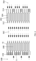
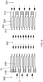
FIG. 4 is a partial schematic diagram of a plate heat exchanger according to an embodiment of the present invention, showing a first heat transfer medium port, a second heat transfer medium port, and a third heat transfer medium port, with the ratio of the number of first heat exchange spaces to the number of second heat exchange spaces being 3; -
FIG. 5 is a partial schematic diagram of a plate heat exchanger according to an embodiment of the present invention, showing a first heat transfer medium port, a second heat transfer medium port, and a third heat transfer medium port, with the ratio of the number of first heat exchange spaces to the number of second heat exchange spaces being 2; -
FIG. 6 is a partial schematic diagram of a plate heat exchanger according to an embodiment of the present invention, showing a first heat transfer medium port, a second heat transfer medium port, and a third heat transfer medium port, with the ratio of the number of first heat exchange spaces to the number of second heat exchange spaces being 1.5; -
FIG. 7 is a partial schematic diagram of a plate heat exchanger according to a variant of the embodiment shown inFIG. 6 , showing a first heat transfer medium port, a second heat transfer medium port, and a third heat transfer medium port, with the ratio of the number of first heat exchange spaces to the number of second heat exchange spaces being 1.5, and the first heat exchange spaces and the second heat exchange spaces being arranged in another exemplary manner; -
FIG. 8 is a partial schematic diagram of a plate heat exchanger according to another variant of the embodiment shown inFIG. 6 , showing a first heat transfer medium port, a second heat transfer medium port, and a third heat transfer medium port, with the ratio of the number of first heat exchange spaces to the number of second heat exchange spaces being 1.5, and the first heat exchange spaces and the second heat exchange spaces being arranged in another exemplary manner; and -
FIG. 9 is a partial schematic diagram of a plate heat exchanger according to another variant of the embodiment shown inFIG. 6 , showing a first heat transfer medium port, a second heat transfer medium port, and a third heat transfer medium port, with the ratio of the number of first heat exchange spaces to the number of second heat exchange spaces being 1.5, and the first heat exchange spaces and the second heat exchange spaces being arranged in another exemplary manner. - The present invention will be further described below in conjunction with the drawings and particular embodiments.
- Referring to
FIGS. 1 and4 to 9 , aplate heat exchanger 100 according to the embodiments of the present invention includes a plurality ofheat transfer plates 10, and heat exchange spaces formed between adjacentheat transfer plates 10 of the plurality ofheat transfer plates 10, the heat exchange spaces including a plurality of firstheat exchange spaces 20A for a first heat transfer medium, a plurality of secondheat exchange spaces 20B for a second heat transfer medium, and a plurality of thirdheat exchange spaces 20C for a third heat transfer medium, and each of the plurality of firstheat exchange spaces 20A and the plurality of secondheat exchange spaces 20B being adjacent to one or two of the plurality of thirdheat exchange spaces 20C, for example, adjacent to two of the plurality of thirdheat exchange spaces 20C, in an overlapping direction of theheat transfer plates 10. As an example, the number of the plurality of firstheat exchange spaces 20A is greater than the number of the plurality of secondheat exchange spaces 20B. The ratio of the number of the plurality of firstheat exchange spaces 20A to the number of the plurality of secondheat exchange spaces 20B is greater than 1, for example, greater than 1.05, 1.1, 1.15, etc. The ratio of the number of the plurality of firstheat exchange spaces 20A to the number of the plurality of secondheat exchange spaces 20B may be between 1.1 and 5. As shown in the figures, theplate heat exchanger 100 is a dual-circuit heat exchanger. The firstheat exchange space 20A, the secondheat exchange space 20B and the thirdheat exchange space 20C are independent of each other. Each of the plurality of firstheat exchange spaces 20A and the plurality of secondheat exchange spaces 20B is adjacent to one thirdheat exchange space 20C on either side in the overlapping direction of the heat transfer plates. Each of the plurality of thirdheat exchange spaces 20C is adjacent to the firstheat exchange space 20A or the secondheat exchange space 20B on either side in the overlapping direction of the heat transfer plates. The first heat transfer medium in the firstheat exchange space 20A exchanges heat with a third heat exchange medium in the thirdheat exchange space 20C, and the second heat transfer medium in the secondheat exchange space 20B exchanges heat with the third heat exchange medium in the thirdheat exchange space 20C. Depending on operation requirements of a system, only a circuit where the firstheat exchange spaces 20A are located or only a circuit where the secondheat exchange spaces 20B are located, or both the circuit where the firstheat exchange spaces 20A are located and the circuit where the secondheat exchange spaces 20B are located may be operated. Theoretically, if the sum of the number of firstheat exchange spaces 20A and the number of secondheat exchange spaces 20B is N, there are (N-1) ratios of the number of firstheat exchange spaces 20A to the number of secondheat exchange spaces 20B. - Referring to
FIGS. 4 to 7 andFIG. 9 , according to the embodiments of the present invention, a plurality of groups of first heat exchange spaces and a plurality of groups of second heat exchange spaces are alternately arranged in the overlapping direction of theheat transfer plates 10. In this way, taking an evaporator as an example, for example, when only one circuit is operated, the third heat transfer medium in the third heat exchange space adjacent to the other circuit can be prevented from freezing. Each group of the plurality of groups of first heat exchange spaces includes one or more firstheat exchange spaces 20A, and each group of the plurality of groups of second heat exchange spaces includes one or more secondheat exchange spaces 20B. At least two groups of first heat exchange spaces of the plurality of groups of first heat exchange spaces may include the same number or different numbers of firstheat exchange spaces 20A ; and/or at least two groups of second heat exchange spaces of the plurality of groups of second heat exchange spaces may include the same number or different numbers of secondheat exchange spaces 20B. - Referring to
FIGS. 8 and9 , according to the embodiments of the present invention, with respect to the firstheat exchange spaces 20A and the secondheat exchange spaces 20B (i.e., without considering the thirdheat exchange spaces 20C), the plurality of firstheat exchange spaces 20A are successively arranged in the overlapping direction of theheat transfer plates 10; and/or with respect to the firstheat exchange spaces 20A and the secondheat exchange spaces 20B (i.e., without considering the thirdheat exchange spaces 20C), the plurality of secondheat exchange spaces 20B are successively arranged in the overlapping direction of theheat transfer plates 10. - Referring to
FIGS. 4 to 9 , according to embodiments of the present invention, a plurality of heat exchange spaces, composed of the plurality of firstheat exchange spaces 20A and the plurality of secondheat exchange spaces 20B, and the plurality of thirdheat exchange spaces 20C are alternately arranged in the overlapping direction of theheat transfer plates 10. - According to an embodiment of the present invention, if the ratio of the number of first
heat exchange spaces 20A to the number of secondheat exchange spaces 20B is defined as λ, the number of arrangement modes of the firstheat exchange spaces 20A and the secondheat exchange spaces 20B is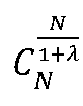
- Referring to
FIGS. 1 and4 to 9 , theplate heat exchanger 100 according to the embodiments of the present invention further includes: a pair of first heattransfer medium ports 30A for the first heat transfer medium to flow into the plurality of firstheat exchange spaces 20A and for the first heat transfer medium to flow out of the plurality of firstheat exchange spaces 20A, respectively; a pair of second heattransfer medium ports 30B for the second heat transfer medium to flow into the plurality of secondheat exchange spaces 20B and for the second heat transfer medium to flow out of the plurality of secondheat exchange spaces 20B, respectively; and a pair of third heattransfer medium ports 30C for the third heat transfer medium to flow into the plurality of thirdheat exchange spaces 20C and for the third heat transfer medium to flow out of the plurality of thirdheat exchange spaces 20C, respectively. In the example shown inFIG. 1 , the first heattransfer medium port 30A and the second heattransfer medium port 30B located at a lower side of theplate heat exchanger 100 are heat transfer medium inflow ports, and the first heattransfer medium port 30A and the second heattransfer medium port 30B located at an upper side of theplate heat exchanger 100 are heat transfer medium outflow ports; and the third heattransfer medium port 30C located at the lower side of theplate heat exchanger 100 is a heat transfer medium outflow port, and the third heattransfer medium port 30C located at the upper side of theplate heat exchanger 100 is a heat transfer medium inflow port. The first heat transfer medium and the second heat transfer medium may be the same or different, the first heat transfer medium and the second heat transfer medium may be refrigerants, and the third heat transfer medium may be a secondary refrigerant, such as water, an ethylene glycol solution or an ethanol solution. There is a temperature difference between the temperature of the first heat transfer medium and the second heat transfer medium and the temperature of the third heat exchange medium such that heat exchange is performed when theplate heat exchanger 100 is in operation. - Referring to
FIG. 1 , according to an embodiment of the present invention, one of the pair of first heattransfer medium ports 30A is arranged at the upper left corner of theheat transfer plate 10, the other of the pair of first heattransfer medium ports 30A is arranged at the lower left corner of theheat transfer plate 10, one of the pair of second heattransfer medium ports 30B is arranged at the upper right corner of theheat transfer plate 10, and the other of the pair of second heattransfer medium ports 30B is arranged at the lower right corner of theheat transfer plate 10, thereby defining a parallel-flow heat exchange mode. Alternatively, one of the pair of first heattransfer medium ports 30A is arranged at the upper left corner of theheat transfer plate 10, the other of the pair of first heattransfer medium ports 30A is arranged at the lower right corner of theheat transfer plate 10, one of the pair of second heattransfer medium ports 30B is arranged at the upper right corner of theheat transfer plate 10, and the other of the pair of second heattransfer medium ports 30B is arranged at the lower left corner of theheat transfer plate 10, thereby defining a cross-flow heat exchange mode. In the embodiment shown in the figure, the third heattransfer medium ports 30C are each arranged between the first heattransfer medium port 30A and the second heattransfer medium port 30B on the upper side of theplate heat exchanger 100 and the lower side of theplate heat exchanger 100. - Referring to
FIGS. 4 to 9 , according to the embodiments of the present invention, each of the pair of first heattransfer medium ports 30A has a plurality offirst openings 31A leading to the plurality of firstheat exchange spaces 20A; each of the pair of second heattransfer medium ports 30B has a plurality ofsecond openings 31B leading to the plurality of secondheat exchange spaces 20B; and each of the pair of third heattransfer medium ports 30C has a plurality ofthird openings 31C leading to the plurality of thirdheat exchange spaces 20C. In the figures, the positions of all the openings are indicated by arrows. At the ports, ablocking ring 5 is arranged between adjacentheat transfer plates 10 at positions without an opening, and each opening is formed between adjacentheat transfer plates 10 at positions without ablocking ring 5. Alternatively, a distributor is provided in the port, and the distributor has openings leading to the heat exchange spaces. In addition, the openings leading to the heat exchange spaces may also be formed in other suitable ways. - According to an embodiment of the present invention, the ratio of the number of first
heat exchange spaces 20A to the number of secondheat exchange spaces 20B is greater than 1, so that the heat transfer area of each circuit can be optimized, so as to improve the heat exchange efficiency. By optimizing the heat transfer area of each circuit according to the heat load of each circuit, the system efficiency can be improved by 5% to 10% under full load and partial load, and reliability problems such as retention of the heat transfer medium are also avoided. In addition, adjusting the ratio of the number of firstheat exchange spaces 20A to the number of secondheat exchange spaces 20B will not affect the feasibility of product manufacturing and will not cause an increase in costs. - Although the above embodiments describe the specific ratio of the number of first
heat exchange spaces 20A to the number of secondheat exchange spaces 20B and the specific arrangement mode of the firstheat exchange spaces 20A and the secondheat exchange spaces 20B, the present invention is not limited to the above embodiments, the ratio of the number of firstheat exchange spaces 20A to the number of secondheat exchange spaces 20B may be any other value greater than 1, and the firstheat exchange spaces 20A and the secondheat exchange spaces 20B can be arranged in any other way.
Claims (13)
- A plate heat exchanger, comprising:a plurality of heat transfer plates; andheat exchange spaces formed between adjacent heat transfer plates of the plurality of heat transfer plates, the heat exchange spaces comprising a plurality of first heat exchange spaces for a first heat transfer medium, a plurality of second heat exchange spaces for a second heat transfer medium, and a plurality of third heat exchange spaces for a third heat transfer medium, and each of the plurality of first heat exchange spaces and the plurality of second heat exchange spaces being adjacent to one or two of the plurality of third heat exchange spaces in an overlapping direction of the heat transfer plates,wherein the number of the plurality of first heat exchange spaces is different from the number of the plurality of second heat exchange spaces.
- The plate heat exchanger of claim 1, wherein
the ratio of the greater one of the number of the plurality of first heat exchange spaces and the number of the plurality of second heat exchange spaces to the smaller one of the number of the plurality of first heat exchange spaces and the number of the plurality of second heat exchange spaces is greater than 1.05. - The plate heat exchanger of claim 1, wherein
the ratio of the greater one of the number of the plurality of first heat exchange spaces and the number of the plurality of second heat exchange spaces to the smaller one of the number of the plurality of first heat exchange spaces and the number of the plurality of second heat exchange spaces is between 1.1 and 5. - The plate heat exchanger of claim 1, wherein
a plurality of groups of first heat exchange spaces and a plurality of groups of second heat exchange spaces are alternately arranged in the overlapping direction of the heat transfer plates, each group of the plurality of groups of first heat exchange spaces comprises one or more first heat exchange spaces, and each group of the plurality of groups of second heat exchange spaces comprises one or more second heat exchange spaces. - The plate heat exchanger of claim 4, whereinat least two groups of first heat exchange spaces of the plurality of groups of first heat exchange spaces comprise the same number or different numbers of first heat exchange spaces; and/orat least two groups of second heat exchange spaces of the plurality of groups of second heat exchange spaces comprise the same number or different numbers of second heat exchange spaces.
- The plate heat exchanger of claim 1, whereinwith respect to the first heat exchange spaces and the second heat exchange spaces, the plurality of first heat exchange spaces are successively arranged in the overlapping direction of the heat transfer plates; and/orwith respect to the first heat exchange spaces and the second heat exchange spaces, the plurality of second heat exchange spaces are successively arranged in the overlapping direction of the heat transfer plates.
- The plate heat exchanger of claim 1, wherein
a plurality of heat exchange spaces, composed of the plurality of first heat exchange spaces and the plurality of second heat exchange spaces, and the plurality of third heat exchange spaces are alternately arranged in the overlapping direction of the heat transfer plates. - The plate heat exchanger of claim 1, further comprising:a pair of first heat transfer medium ports for the first heat transfer medium to flow into the plurality of first heat exchange spaces and for the first heat transfer medium to flow out of the plurality of first heat exchange spaces, respectively;a pair of second heat transfer medium ports for the second heat transfer medium to flow into the plurality of second heat exchange spaces and for the second heat transfer medium to flow out of the plurality of second heat exchange spaces, respectively; anda pair of third heat transfer medium ports for the third heat transfer medium to flow into the plurality of third heat exchange spaces and for the third heat transfer medium to flow out of the plurality of third heat exchange spaces, respectively.
- The plate heat exchanger of claim 8, whereinone of the pair of first heat transfer medium ports is arranged at the upper left corner of the heat transfer plate, the other of the pair of first heat transfer medium ports is arranged at the lower left corner of the heat transfer plate, one of the pair of second heat transfer medium ports is arranged at the upper right corner of the heat transfer plate, and the other of the pair of second heat transfer medium ports is arranged at the lower right corner of the heat transfer plate; orone of the pair of first heat transfer medium ports is arranged at the upper left corner of the heat transfer plate, the other of the pair of first heat transfer medium ports is arranged at the lower right corner of the heat transfer plate, one of the pair of second heat transfer medium ports is arranged at the upper right corner of the heat transfer plate, and the other of the pair of second heat transfer medium ports is arranged at the lower left corner of the heat transfer plate.
- The plate heat exchanger of claim 8, whereineach of the pair of first heat transfer medium ports has a plurality of first openings leading to the plurality of first heat exchange spaces;each of the pair of second heat transfer medium ports has a plurality of second openings leading to the plurality of second heat exchange spaces; andeach of the pair of third heat transfer medium ports has a plurality of third openings leading to the plurality of third heat exchange spaces.
- The plate heat exchanger of any one of claims 1 to 10, wherein each of the plurality of first heat exchange spaces and the plurality of second heat exchange spaces is adjacent to the third heat exchange space on either side in the overlapping direction of the heat transfer plates; and/or
each of the plurality of third heat exchange spaces is adjacent to the first heat exchange space or the second heat exchange space on either side in the overlapping direction of the heat transfer plates. - The plate heat exchanger of any one of claims 1 to 10, wherein
the first heat transfer medium and the second heat transfer medium are refrigerants, and the third heat transfer medium is a secondary refrigerant. - The plate heat exchanger of any one of claims 1 to 10, wherein
the first heat exchange space, the second heat exchange space and the third heat exchange space are independent of each other.
Applications Claiming Priority (3)
| Application Number | Priority Date | Filing Date | Title |
|---|---|---|---|
| CN202220680222.2U CN217764597U (en) | 2022-03-25 | 2022-03-25 | Plate heat exchanger |
| CN202210308874.8A CN116839395B (en) | 2022-03-25 | 2022-03-25 | Plate heat exchanger |
| PCT/CN2023/078407 WO2023179313A1 (en) | 2022-03-25 | 2023-02-27 | Plate heat exchanger |
Publications (2)
| Publication Number | Publication Date |
|---|---|
| EP4502521A1 true EP4502521A1 (en) | 2025-02-05 |
| EP4502521A4 EP4502521A4 (en) | 2025-12-24 |
Family
ID=88099925
Family Applications (1)
| Application Number | Title | Priority Date | Filing Date |
|---|---|---|---|
| EP23773564.2A Pending EP4502521A4 (en) | 2022-03-25 | 2023-02-27 | PLATE HEAT EXCHANGER |
Country Status (4)
| Country | Link |
|---|---|
| US (1) | US20250198705A1 (en) |
| EP (1) | EP4502521A4 (en) |
| MX (1) | MX2024011192A (en) |
| WO (1) | WO2023179313A1 (en) |
Family Cites Families (19)
| Publication number | Priority date | Publication date | Assignee | Title |
|---|---|---|---|---|
| US4327802A (en) * | 1979-06-18 | 1982-05-04 | Borg-Warner Corporation | Multiple fluid heat exchanger |
| JP2700150B2 (en) * | 1988-03-25 | 1998-01-19 | 株式会社日阪製作所 | Plate heat exchanger |
| JP2843886B2 (en) * | 1989-03-28 | 1999-01-06 | 株式会社日阪製作所 | Three-liquid plate heat exchanger |
| JP2887406B2 (en) * | 1990-07-10 | 1999-04-26 | 株式会社日阪製作所 | Plate heat exchanger |
| JPH1019482A (en) * | 1996-06-28 | 1998-01-23 | Toshiba Eng Co Ltd | Plate heat exchanger |
| JP3936088B2 (en) * | 1998-12-08 | 2007-06-27 | 大阪瓦斯株式会社 | Three-fluid plate heat exchanger and method for manufacturing the same |
| JP2000337784A (en) * | 1999-05-24 | 2000-12-08 | Nhk Spring Co Ltd | Plate heat exchanger for three liquids |
| JP4082029B2 (en) * | 2001-12-28 | 2008-04-30 | ダイキン工業株式会社 | Plate heat exchanger |
| DE102004020602A1 (en) * | 2004-04-27 | 2005-12-01 | Mahle Filtersysteme Gmbh | Plate heat exchanger for internal combustion engine, has plate gaps with another two plate gaps, which guide one of three heat exchange fluids, where fluids are exchanged with each other in adjoining gaps in respective same row sequence |
| JP2006322692A (en) * | 2005-05-20 | 2006-11-30 | Ebara Corp | Steam generator and exhaust heat power generating device |
| JP2007178100A (en) * | 2005-12-28 | 2007-07-12 | Hisaka Works Ltd | Plate heat exchanger |
| EP1850082A1 (en) * | 2006-04-24 | 2007-10-31 | Sundsvall Energi AB | Heat exchanger |
| JP5174739B2 (en) * | 2009-05-08 | 2013-04-03 | 株式会社日阪製作所 | Plate heat exchanger and heat exchange unit equipped with the same |
| JP6196908B2 (en) * | 2014-01-24 | 2017-09-13 | 株式会社日阪製作所 | Plate heat exchanger |
| JP6306901B2 (en) * | 2014-03-05 | 2018-04-04 | 株式会社日阪製作所 | Plate heat exchanger |
| CN109477693A (en) * | 2016-07-11 | 2019-03-15 | 新加坡国立大学 | Multi-fluid heat exchanger |
| DE112018004787T5 (en) * | 2017-08-31 | 2020-06-25 | Dana Canada Corporation | MULTI-FLUID HEAT EXCHANGER |
| JP7100074B2 (en) * | 2020-01-24 | 2022-07-12 | 株式会社日阪製作所 | Plate heat exchanger |
| CN217764597U (en) * | 2022-03-25 | 2022-11-08 | 丹佛斯有限公司 | Plate heat exchanger |
-
2023
- 2023-02-27 MX MX2024011192A patent/MX2024011192A/en unknown
- 2023-02-27 EP EP23773564.2A patent/EP4502521A4/en active Pending
- 2023-02-27 WO PCT/CN2023/078407 patent/WO2023179313A1/en not_active Ceased
- 2023-02-27 US US18/847,836 patent/US20250198705A1/en active Pending
Also Published As
| Publication number | Publication date |
|---|---|
| MX2024011192A (en) | 2024-09-18 |
| EP4502521A4 (en) | 2025-12-24 |
| WO2023179313A1 (en) | 2023-09-28 |
| US20250198705A1 (en) | 2025-06-19 |
Similar Documents
| Publication | Publication Date | Title |
|---|---|---|
| US20220364793A1 (en) | Plate, plate assembly and heat exchanger | |
| EP3786566B1 (en) | Microchannel flat tube and microchannel heat exchanger | |
| US20240295365A1 (en) | Plate heat exchanger having a large number of heat exchange compartments | |
| EP3832243A1 (en) | Multi-stage flow distribution plate group for heat exchanger | |
| EP0183008A1 (en) | Plate - stacked heat exchanger | |
| GB2052722A (en) | Multiple fluid heat exchanger | |
| US20140374072A1 (en) | Kit for a heat exchanger, a heat exchanger core, and heat exchanger | |
| US20240326548A1 (en) | Heat exchanger for a motor vehicle | |
| CN217764597U (en) | Plate heat exchanger | |
| US20250189236A1 (en) | Internal heat exchanger with plates | |
| US20250198705A1 (en) | Plate heat exchanger | |
| US20220120506A1 (en) | Universal heat exchanger | |
| US20090249810A1 (en) | Evaporator | |
| JP2009275969A (en) | Refrigerating apparatus | |
| CN116839395B (en) | Plate heat exchanger | |
| JP2874517B2 (en) | Stacked heat exchanger | |
| JP2000258082A (en) | Water / refrigerant heat exchanger | |
| JP2584060B2 (en) | Stacked heat exchanger | |
| EP3872434B1 (en) | A plate assembly | |
| JP2649421B2 (en) | Heat exchanger | |
| CN115939566A (en) | Heat exchanger and new energy vehicle thermal management system | |
| CN223470360U (en) | Immersed heat exchangers and thermal management systems | |
| US12595969B2 (en) | Heat exchanger for a motor vehicle | |
| WO2025249920A1 (en) | Plate heat exchanger with improved flow distribution | |
| JPH03129270A (en) | Lamination type evaporator |
Legal Events
| Date | Code | Title | Description |
|---|---|---|---|
| STAA | Information on the status of an ep patent application or granted ep patent |
Free format text: STATUS: THE INTERNATIONAL PUBLICATION HAS BEEN MADE |
|
| PUAI | Public reference made under article 153(3) epc to a published international application that has entered the european phase |
Free format text: ORIGINAL CODE: 0009012 |
|
| STAA | Information on the status of an ep patent application or granted ep patent |
Free format text: STATUS: REQUEST FOR EXAMINATION WAS MADE |
|
| 17P | Request for examination filed |
Effective date: 20240927 |
|
| AK | Designated contracting states |
Kind code of ref document: A1 Designated state(s): AL AT BE BG CH CY CZ DE DK EE ES FI FR GB GR HR HU IE IS IT LI LT LU LV MC ME MK MT NL NO PL PT RO RS SE SI SK SM TR |
|
| DAV | Request for validation of the european patent (deleted) | ||
| DAX | Request for extension of the european patent (deleted) | ||
| A4 | Supplementary search report drawn up and despatched |
Effective date: 20251126 |
|
| RIC1 | Information provided on ipc code assigned before grant |
Ipc: F28D 9/04 20060101AFI20251120BHEP Ipc: F28F 3/08 20060101ALI20251120BHEP Ipc: F28D 9/00 20060101ALI20251120BHEP Ipc: F28F 3/10 20060101ALI20251120BHEP |