EP4502520A1 - Plate heat exchanger - Google Patents
Plate heat exchanger Download PDFInfo
- Publication number
- EP4502520A1 EP4502520A1 EP24187702.6A EP24187702A EP4502520A1 EP 4502520 A1 EP4502520 A1 EP 4502520A1 EP 24187702 A EP24187702 A EP 24187702A EP 4502520 A1 EP4502520 A1 EP 4502520A1
- Authority
- EP
- European Patent Office
- Prior art keywords
- plate
- heat transfer
- end plate
- annular
- transfer plate
- Prior art date
- Legal status (The legal status is an assumption and is not a legal conclusion. Google has not performed a legal analysis and makes no representation as to the accuracy of the status listed.)
- Granted
Links
Images






Classifications
-
- F—MECHANICAL ENGINEERING; LIGHTING; HEATING; WEAPONS; BLASTING
- F28—HEAT EXCHANGE IN GENERAL
- F28D—HEAT-EXCHANGE APPARATUS, NOT PROVIDED FOR IN ANOTHER SUBCLASS, IN WHICH THE HEAT-EXCHANGE MEDIA DO NOT COME INTO DIRECT CONTACT
- F28D9/00—Heat-exchange apparatus having stationary plate-like or laminated conduit assemblies for both heat-exchange media, the media being in contact with different sides of a conduit wall
- F28D9/0031—Heat-exchange apparatus having stationary plate-like or laminated conduit assemblies for both heat-exchange media, the media being in contact with different sides of a conduit wall the conduits for one heat-exchange medium being formed by paired plates touching each other
- F28D9/0043—Heat-exchange apparatus having stationary plate-like or laminated conduit assemblies for both heat-exchange media, the media being in contact with different sides of a conduit wall the conduits for one heat-exchange medium being formed by paired plates touching each other the plates having openings therein for circulation of at least one heat-exchange medium from one conduit to another
- F28D9/005—Heat-exchange apparatus having stationary plate-like or laminated conduit assemblies for both heat-exchange media, the media being in contact with different sides of a conduit wall the conduits for one heat-exchange medium being formed by paired plates touching each other the plates having openings therein for circulation of at least one heat-exchange medium from one conduit to another the plates having openings therein for both heat-exchange media
-
- F—MECHANICAL ENGINEERING; LIGHTING; HEATING; WEAPONS; BLASTING
- F28—HEAT EXCHANGE IN GENERAL
- F28D—HEAT-EXCHANGE APPARATUS, NOT PROVIDED FOR IN ANOTHER SUBCLASS, IN WHICH THE HEAT-EXCHANGE MEDIA DO NOT COME INTO DIRECT CONTACT
- F28D9/00—Heat-exchange apparatus having stationary plate-like or laminated conduit assemblies for both heat-exchange media, the media being in contact with different sides of a conduit wall
- F28D9/0031—Heat-exchange apparatus having stationary plate-like or laminated conduit assemblies for both heat-exchange media, the media being in contact with different sides of a conduit wall the conduits for one heat-exchange medium being formed by paired plates touching each other
-
- F—MECHANICAL ENGINEERING; LIGHTING; HEATING; WEAPONS; BLASTING
- F28—HEAT EXCHANGE IN GENERAL
- F28D—HEAT-EXCHANGE APPARATUS, NOT PROVIDED FOR IN ANOTHER SUBCLASS, IN WHICH THE HEAT-EXCHANGE MEDIA DO NOT COME INTO DIRECT CONTACT
- F28D9/00—Heat-exchange apparatus having stationary plate-like or laminated conduit assemblies for both heat-exchange media, the media being in contact with different sides of a conduit wall
- F28D9/0093—Multi-circuit heat-exchangers, e.g. integrating different heat exchange sections in the same unit or heat-exchangers for more than two fluids
-
- F—MECHANICAL ENGINEERING; LIGHTING; HEATING; WEAPONS; BLASTING
- F28—HEAT EXCHANGE IN GENERAL
- F28F—DETAILS OF HEAT-EXCHANGE AND HEAT-TRANSFER APPARATUS, OF GENERAL APPLICATION
- F28F3/00—Plate-like or laminated elements; Assemblies of plate-like or laminated elements
- F28F3/08—Elements constructed for building-up into stacks, e.g. capable of being taken apart for cleaning
- F28F3/10—Arrangements for sealing the margins
-
- F—MECHANICAL ENGINEERING; LIGHTING; HEATING; WEAPONS; BLASTING
- F28—HEAT EXCHANGE IN GENERAL
- F28F—DETAILS OF HEAT-EXCHANGE AND HEAT-TRANSFER APPARATUS, OF GENERAL APPLICATION
- F28F9/00—Casings; Header boxes; Auxiliary supports for elements; Auxiliary members within casings
- F28F9/26—Arrangements for connecting different sections of heat-exchange elements, e.g. of radiators
-
- F—MECHANICAL ENGINEERING; LIGHTING; HEATING; WEAPONS; BLASTING
- F28—HEAT EXCHANGE IN GENERAL
- F28F—DETAILS OF HEAT-EXCHANGE AND HEAT-TRANSFER APPARATUS, OF GENERAL APPLICATION
- F28F2230/00—Sealing means
-
- F—MECHANICAL ENGINEERING; LIGHTING; HEATING; WEAPONS; BLASTING
- F28—HEAT EXCHANGE IN GENERAL
- F28F—DETAILS OF HEAT-EXCHANGE AND HEAT-TRANSFER APPARATUS, OF GENERAL APPLICATION
- F28F2275/00—Fastening; Joining
- F28F2275/04—Fastening; Joining by brazing
Definitions
- the present disclosure relates to a plate heat exchanger.
- a traditional plate heat exchanger comprises two end plates (the two end plates may also be referred to as an end plate and a bottom plate or a cover plate and a bottom plate, respectively) and at least one heat transfer plate between the two end plates.
- Fluid channels used for two or more fluids are formed between adjacent heat transfer plates so as to conduct heat exchange among the two or more fluids.
- a purpose of the embodiments of the present disclosure is to provide a plate heat exchanger, thereby such as reducing a number of parts.
- An embodiment of the present disclosure provides a plate heat exchanger comprising: a plurality of heat transfer plates; a first fluid channel and a second fluid channel formed between adjacent heat transfer plates and fluidly isolated from each other, wherein the first fluid channel comprises a fluid channel upstream portion and a fluid channel downstream portion that are separated from each other; an upstream outlet port formed in each of the heat transfer plates and communicated to the fluid channel upstream portion of the first fluid channel, and a downstream inlet port formed in each of the heat transfer plates and communicated to the fluid channel downstream portion of the first fluid channel; and a fluid communication device, through which the upstream outlet port and the downstream inlet port are fluidly communicated with each other.
- the plate heat exchanger further comprises: an end plate disposed on an outer side of an outermost heat transfer plate and having an end plate outer recess that is recessed in a direction away from the outermost heat transfer plate, wherein the end plate outer recess is configured to form a chamber as the fluid communication device with a portion of the outermost heat transfer plate corresponding to the end plate outer recess.
- the plate heat exchanger further comprises: a sealing plate comprising: first and second openings; and first and second annular protrusions respectively surrounding the first and second openings and protruding towards their sides facing away from the end plate; and wherein the sealing plate is disposed between the end plate and the outermost heat transfer plate.
- annular edge surface portion of the sealing plate on a side of the sealing plate facing the end plate is in contact with an annular surface portion of the end plate surrounding the end plate outer recess so as to form a seal between the annular edge surface portion of the sealing plate and the annular surface portion of the end plate
- first and second annular protrusions of the sealing plate are in contact with a first annular surface portion around the upstream outlet port of the outermost heat transfer plate and a second annular surface portion around the downstream inlet port of the outermost heat transfer plate, respectively, so as to form a seal between the first annular protrusion of the sealing plate and the first annular surface portion of the outermost heat transfer plate and a seal between the second annular protrusion of the sealing plate and the second annular surface portion of the outermost heat transfer plate, respectively.
- the outermost heat transfer plate is configured to have first and second heat transfer plate recesses recessed towards its side facing away from the end plate, and the first annular surface portion of the outermost heat transfer plate is disposed in a bottom of the first heat transfer plate recess of the outermost heat transfer plate, and the second annular surface portion of the outermost heat transfer plate is disposed in a bottom of the second heat transfer plate recess of the outermost heat transfer plate.
- the plate heat exchanger further comprises: a sealing plate comprising: an opening; and an annular protrusion protruding surrounding the opening and protruding towards its side facing away from the end plate; and wherein the sealing plate is disposed between the end plate and the outermost heat transfer plate.
- annular edge surface portion of the sealing plate on a side of the sealing plate facing the end plate is in contact with an annular surface portion of the end plate surrounding the end plate outer recess so as to form a seal between the annular edge surface portion of the sealing plate and the annular surface portion of the end plate
- the annular protrusion of the sealing plate is in contact with the annular surface portion around the upstream outlet port and downstream inlet port of the outermost heat transfer plate so as to form a seal between the annular protrusion of the sealing plate and the annular surface portion of the outermost heat transfer plate.
- the outermost heat transfer plate is configured to have a heat transfer plate recess that is recessed towards its side facing away from the end plate, and the annular surface portion of the outermost heat transfer plate is disposed in the bottom of the heat transfer plate recess of the outermost heat transfer plate.
- the end plate is configured to further have a step portion surrounding the end plate outer recess and recessed in a direction away from the outermost heat transfer plate, and the annular surface portion of the end plate surrounding the end plate outer recess is disposed on the step portion.
- the sealing plate is formed of metal and connected to the end plate and the outermost heat transfer plate through brazing respectively.
- the annular surface portion of the end plate surrounding the end plate outer recess is in contact with the annular surface portion of the outermost heat transfer plate around the upstream outlet port and downstream inlet port so as to form a seal between the annular surface portion of the end plate and the annular surface portion of the outermost heat transfer plate.
- the outermost heat transfer plate is configured to have an annular heat transfer plate recess around the upstream outlet port and downstream inlet port and recessed in a direction away from the end plate, and a bottom of the annular heat transfer plate recess of the outermost heat transfer plate is in contact with an adjacent heat transfer plate so as to form a seal between the bottom of the annular heat transfer plate recess of the outermost heat transfer plate and the adjacent heat transfer plate.
- the outermost heat transfer plate is configured to have a plurality of separated heat transfer plate recesses around the upstream outlet port and downstream inlet port and recessed in a direction away from the end plate, and bottoms of the plurality of separated heat transfer plate recesses of the outermost heat transfer plate are in contact with an adjacent heat transfer plate respectively.
- the heat transfer plate recess of the outermost heat transfer plate is located on an inner and/or outer side of the annular surface portion of the outermost heat transfer plate.
- the plate heat exchanger further comprises: an end plate disposed on an outer side of the outermost heat transfer plate and having an opening; and a chamber plate comprising: an annular plate portion disposed between the annular plate portion of the end plate surrounding the opening of the end plate and the annular surface portion of the outermost heat transfer plate around the upstream outlet port and downstream inlet port so as to form seals between the annular plate portion of the end plate and the annular plate portion of the chamber plate, as well as between the annular plate portion of the chamber plate and the annular surface portion of the outermost heat transfer plate; and a chamber plate recess recessed to an outer side of the end plate through the opening of the end plate from the annular plate portion of the chamber plate in a direction away from the outermost heat transfer plate, the chamber plate recess and a portion of the outermost heat transfer plate corresponding to the chamber plate recess forming a chamber as the fluid communication device.
- the outermost heat transfer plate is configured to have a heat transfer plate recess that is recessed towards its side facing away from the end plate, and the annular surface portion of the outermost heat transfer plate is disposed in a bottom of the heat transfer plate recess of the outermost heat transfer plate.
- the plate heat exchanger further comprises: an end plate disposed on an outer side of the outermost heat transfer plate and having a first through hole communicated to the upstream outlet port and a second through hole communicated to the downstream inlet port.
- the end plate is configured to have first and second end plate inner recesses that are recessed to its side facing towards the outermost heat transfer plate respectively, and the first and second through holes of the end plate are respectively disposed in a bottom of the first end plate inner recess and a bottom of the second end plate inner recess of the end plate, a first annular bottom surface of the bottom of the first end plate inner recess of the end plate around the first through hole and a second annular bottom surface of the bottom of the second end plate inner recess of the end plate around the second through hole are in contact with a first annular surface portion of the outermost heat transfer plate around the upstream outlet port and a second annular surface portion of the outermost heat transfer plate around the downstream inlet port, respectively, so as to form a seal between a first annular bottom surface of the bottom of the first end plate inner recess of the end plate and the first annular surface portion of the outermost heat transfer plate, and a seal between a second annular bottom surface of the bottom of
- the outermost heat transfer plate is configured to have a first heat transfer plate recess and a second heat transfer plate recess, the first annular surface portion of the outermost heat transfer plate is disposed in a bottom of the first heat transfer plate recess of the outermost heat transfer plate, and the second annular surface portion of the outermost heat transfer plate is disposed in a bottom of the second heat transfer plate recess of the outermost heat transfer plate.
- the fluid communication device comprises a communicating tube connected to the end plate so as to connect the first through hole with the second through hole through the communicating tube.
- the communicating tube is generally U-shaped.
- the communicating tube is configured to have a projection protruding outward from its wall.
- the projection of the wall of the communicating tube is located at a portion of the wall of the communicating tube facing away from the end plate.
- Adopting a plate heat exchanger according to the embodiments of the present disclosure may reduce the number of parts.
- a plate heat exchanger 100 according to an embodiment of the present disclosure comprises: a plurality of heat transfer plates 2; a first fluid channel 3 and a second fluid channel 4 formed between adjacent heat transfer plates 2 and fluidly isolated from each other; an upstream outlet port 51 and downstream inlet port 52 formed in each of the heat transfer plates 2; and a fluid communication device 6.
- the first fluid channel 3 comprises a fluid channel upstream portion 31 and a fluid channel downstream portion 32 that are separated from each other.
- the plate heat exchanger 100 further comprises an end plate 7, which is disposed on an outer side of an outermost heat transfer plate 2U.
- the plate heat exchanger 100 further comprises: a first fluid inlet 111, a first fluid outlet 112, a second fluid outlet 122 (for a counter flow evaporator), and a second fluid inlet 121 (for a counter flow evaporator).
- a first fluid such as refrigerant flows in the first fluid channel 3, while a second fluid such as water flows in the second fluid channel 4.
- the heat transfer plates 10 are stacked together, thereby alternately forming the first fluid channel 3 and the second fluid channel 4 in the stacking direction, or alternatively forming three or more fluid channels in the stacking direction.
- the first fluid channel is divided into the fluid channel upstream portion 31 and the fluid channel downstream portion 32, while the second fluid channel is directly communicated.
- the first fluid enters the plate heat exchanger 100 from the first fluid inlet 111, then enters the fluid channel upstream portion 31 of the first fluid channel 3, enters the fluid communication device 6 from the upstream outlet port 51, then enters the downstream inlet port 52 from the fluid communication device 6, then enters the fluid channel downstream portion 32 of the first fluid channel 3, and finally flows out from the first fluid outlet 112.
- the second fluid enters the plate heat exchanger 100 from the second fluid inlet 121, then enters the second fluid channel, and finally flows out from the second fluid outlet 122.
- the end plate 7 is configured to have an end plate outer recess 70 that is recessed in a direction away from the outermost heat transfer plate 2U.
- the end plate outer recess 70 is configured to form a chamber 60 as the fluid communication device 6 with a corresponding portion of the outermost heat transfer plate 2U.
- the plate heat exchanger 100 further comprises a sealing plate 8, wherein the sealing plate 8 comprises first and second openings 80A, 80B; and first and second annular protrusions 81A, 81B respectively surrounding the first and second openings 80A, 80B and protruding in a direction away from the end plate 7.
- the sealing plate 8 is disposed between the end plate 7 and the outermost heat transfer plate 2U.
- annular edge surface portion 82 of the sealing plate 8 on a side of the sealing plate 8 facing the end plate 7 is in contact with an annular surface portion 71 of the end plate 7 surrounding the end plate outer recess 70 to form a seal between the annular edge surface portion 82 of the sealing plate 8 and the annular surface portion 71 of the end plate 7, and the first and second annular protrusions 81A, 81B of the sealing plate 8 are in contact with the first annular surface portion 20A around the upstream outlet port 51 of the outermost heat transfer plate 2U and the second annular surface portion 20B around the downstream inlet port 52 of the outermost heat transfer plate 2U, respectively, to form a seal between the annular protrusion 81A, 81B of the sealing plate 8 and the annular surface portion 20A, 20B of the outermost heat transfer plate 2U, respectively (i.e., a seal between the annular protrusion 81A and the annular surface portion 20A, and a seal between the annular pro
- the outermost heat transfer plate 2U may have a first heat transfer plate recess 21A and a second heat transfer plate recess 21B recessed towards their sides facing away from the end plate 7.
- the first annular surface portion 20A of the outermost heat transfer plate 2U is disposed in a bottom 22A of the first heat transfer plate recess 21A of the outermost heat transfer plate 2U
- the second annular surface portion 20B of the outermost heat transfer plate 2U is disposed in a bottom 22B of the second heat transfer plate recess 21B of the outermost heat transfer plate 2U.
- the upstream outlet port 51 and downstream inlet port 52 are respectively disposed in the bottom 22A of the first heat transfer plate recess 21A and the bottom 22B of the second heat transfer plate recess 21B of the outermost heat transfer plate 2U.
- the bottom 22A of the first heat transfer plate recess 21A and the bottom 22B of the second heat transfer plate recess 21B of the outermost heat transfer plate 2U respectively come into contact with the annular surface portions of an adj acent heat transfer plate 2N surrounding the upstream outlet port 51 and the downstream inlet port 52 to form a seal, thereby isolating the second fluid passage 4 from the upstream outlet port 51 and the downstream inlet port 52.
- the upstream outlet port 51 is only communicated to the fluid channel upstream portion 31 of the first fluid channel 3, while the downstream inlet port 52 is only communicated to the fluid channel downstream portion 32 of the first fluid channel 3.
- the sealing plate 8 comprises two openings corresponding to the upstream outlet port 51 and the downstream inlet port 52 respectively.
- the sealing plate 8 may only comprise one opening, which corresponds to the upstream outlet port 51 or the downstream inlet port 52.
- the sealing plate comprises: an opening; an annular protrusion protruding surrounding the opening and protruding in a direction away from the end plate 7, wherein, the sealing plate 8 is disposed between the end plate 7 and the outermost heat transfer plate 2U.
- An annular edge surface portion 82 of the sealing plate 8 on the side of the sealing plate 8 facing the end plate 7 is in contact with an annular surface portion 71 of the end plate 7 surrounding the end plate outer recess 70 so as to form a seal between the annular edge surface portion 82 of the sealing plate 8 and the annular surface portion 71 of the end plate 7, and the annular protrusion of the sealing plate 8 is in contact with the annular surface portion around the upstream outlet port 51 and downstream inlet port 52 of the outermost heat transfer plate 2U so as to form a seal between the annular protrusion of the sealing plate 8 and the annular surface portion of the outermost heat transfer plate 2U.
- the outermost heat transfer plate 2U may have a heat transfer plate recess that is recessed towards its side facing away from the end plate 7, and the annular surface portion of the outermost heat transfer plate 2U is disposed in the bottom of the heat transfer plate recess of the outermost heat transfer plate 2U.
- the end plate 7 is configured to further have a step portion 72 surrounding the end plate outer recess 70 and recessed in a direction away from the outermost heat transfer plat 2U.
- the annular surface portion 71 of the end plate 7 surrounding the end plate outer recess 70 is disposed on the step portion 72.
- the sealing plate 8 may be formed of metal and may be connected to the end plate 7 and the outermost heat transfer plate 2U through brazing.
- the end plate has an end plate outer recess 70, which may play a role in regulating a fluid distribution.
- the end plate outer recess 70 By means of the end plate outer recess 70, a separate liquid collection box may be eliminated and a complexity of the brazing process may be reduced.
- the sealing plate may be self-adapted to the step portion 72 of the end plate so as to achieve a precise positioning.
- the sealing plate is made of composite bimetallic materials, such as, a copper is composited on both sides of a stainless steel sealing plate. After the copper is melted at a high temperature, the sealing plate is welded to the end plate and the outermost heat transfer plate respectively. As a result, a process of adding additional solder may be eliminated, thereby reducing a manufacturing complexity and shortening a manufacturing cycle.
- FIG. 7 is a schematic cross-sectional view of a plate heat exchanger taken in a width direction according to a variant of the embodiment shown in FIG. 1 .
- FIG. 8 is a schematic partial enlarged cross-sectional view of the plate heat exchanger shown in FIG. 7 .
- the end plate 7 is in contact with the outermost heat transfer plate 2U, forming a seal and thus eliminating the sealing plate in the embodiments shown in FIGS. 1 to 6C .
- the annular surface portion 71 of the end plate 7 surrounding the end plate outer recess 70 is in contact with the annular surface portion 20 of the outermost heat transfer plate 2U around the upstream outlet port 51 and downstream inlet port 52 so as to form a seal between the annular surface portion 71 of the end plate 7 and the annular surface portion 20 of the outermost heat transfer plate 2U.
- the outermost heat transfer plate 2U is configured to have an annular heat transfer plate recess 23 around the upstream outlet port 51 and downstream inlet port 52 and recessed in a direction away from the end plate 7, and the bottom 24 of the annular heat transfer plate recess 23 of the outermost heat transfer plate 2U is in contact with an adjacent heat transfer plate 2N so as to form a seal between the bottom 24 of the annular heat transfer plate recess 23 of the outermost heat transfer plate 2U and the adjacent heat transfer plate 2N.
- the heat transfer plate recess 23 of the outermost heat transfer plate 2U may be located on an outer side of the annular surface portion 20 of the outermost heat transfer plate 2U. Referring to FIGS.
- the heat transfer plate recess 23 comprises a plurality of discrete heat transfer plate recesses 23.
- the outermost heat transfer plate 2U is configured to have a plurality of separated heat transfer plate recesses 23 around the upstream outlet port 51 and downstream inlet port 52 and recessed in a direction away from the end plate 7, and the bottoms 24 of the plurality of separated heat transfer plate recesses 23 of the outermost heat transfer plate 2U are in contact with an adjacent heat transfer plate 2N.
- a number of the annular heat transfer plate recess 23 of the outermost heat transfer plate 2U may be one, and the one annular heat transfer plate recess 23 surrounds the upstream outlet port 51 and the downstream inlet port 52.
- the number of the annular heat transfer plate recesses 23 may also be two, and the two annular heat transfer plate recesses 23 surround the upstream outlet port 51 and the downstream inlet port 52, respectively.
- the heat transfer plate recess 23 of the outermost heat transfer plate 2U is located on an outer side of the annular surface portion 71 of the outermost heat transfer plate. It may be understood that the heat transfer plate recess 23 of the outermost heat transfer plate 2U may also be located on an inner side of the annular surface portion 71 of the outermost heat transfer plate.
- a sealing connection between the outermost heat transfer plate 2U and the adjacent heat transfer plate 2N may be achieved by an interconnection of the annular portions around the upstream outlet port 51 and the downstream inlet port 52 (referring to a manner of connection of the adjacent heat transfer plates at the downstream inlet port 52 in FIGS. 7 and 8 , where the upper heat transfer plate is configured to have an annular recess surrounding the port, which is hermetically connected to the annular portion of the lower heat transfer plate).
- the end plate is configured to have an end plate outer recess 70, which may regulate the fluid distribution.
- an end plate outer recess 70 Through the end plate outer recess 70, a separate liquid collection box may be eliminated, reducing the complexity of the brazing process.
- the annular surface portion 20 of the outermost heat transfer plate 2U is in contact with the end plate, playing a role of sealing and eliminating a need for a separate sealing ring.
- the end plate 7 is configured to have an opening 73.
- the plate heat exchanger 100 further comprises a chamber plate 9.
- the chamber plate 9 comprises an annular plate portion 90 and the chamber plate recess 91.
- the annular plate portion 90 may be located generally in one plane.
- the annular plate portion 90 is disposed between the annular plate portion 74 of the end plate 7 surrounding the opening 73 of the end plate 7 and the annular surface portion 20 of the outermost heat transfer plate 2U around the upstream outlet port 51 and downstream inlet port 52 so as to form a seal between the annular plate portion 74 of the end plate 7 and the annular plate portion 90 of the chamber plate 9, and a seal between the annular plate portion 90 of the chamber plate 9 and the annular surface portion 20 of the outermost heat transfer plate 2U.
- the chamber plate recess 91 is configured to be recessed to the outer side of the end plate 7 through the opening 73 of the end plate 7 from the annular plate portion 90 of the chamber plate 9 towards a direction away from the outermost heat transfer plate 2U, and the chamber plate recess 91 and a portion of the outermost heat transfer plate 2U corresponding to the chamber plate recess 91 form a chamber 60 as the fluid communication device 6.
- the outermost heat transfer plate 2U may have a heat transfer plate recess 23 that is recessed towards its side facing away from the end plate 7, and the annular surface portion 20 of the outermost heat transfer plate 2U is disposed in the bottom 24 of the heat transfer plate recess 23 of the outermost heat transfer plate 2U.
- the bottom of the heat transfer plate recess of the outermost heat transfer plate is in contact with the annular surface portions of the adjacent heat transfer plates around the upstream outlet port and downstream inlet port so as to form a seal, thereby isolating the second fluid channel from the upstream outlet port and downstream inlet port. Therefore, the upstream outlet port is only communicated to the fluid channel upstream portion of the first fluid channel, while the downstream inlet port is only communicated to the fluid channel downstream portion of the first fluid channel.
- the end plate 7 is configured to have an opening 73.
- the plate heat exchanger 100 further comprises a chamber plate 9.
- the annular plate portion 90 of the chamber plate 9 is sealed between the end plate and the outermost heat transfer plate, and at the same time, the chamber plate recess 91 of the chamber plate 9 forms a chamber 60 as the fluid communication device 6 with the corresponding portion of the outermost heat transfer plate 2U. Therefore, it may regulate the fluid.
- a structure of the plate heat exchanger in accordance with this embodiment is compact, the two functions of the liquid collection box and the sealing ring are combined to one, thereby improving a manufacturing stability and shortening a production cycle of the plate heat exchanger 100.
- FIG. 11 is a schematic partial enlarged cross-sectional view of a plate heat exchanger taken in a length direction according to another embodiment of the present disclosure.
- FIG. 12 is a schematic partial enlarged cross-sectional view of a plate heat exchanger taken in a length direction according to a variant of the embodiment shown in FIG. 11 .
- FIG. 13 is a schematic partial enlarged cross-sectional view of a plate heat exchanger taken in a length direction according to another variant of the embodiment shown in FIG. 11 .
- FIG. 14 is a schematic partial enlarged cross-sectional view of a plate heat exchanger taken in a length direction according to another yet variant of the embodiment shown in FIG. 11 .
- the end plate 7 is configured to have a first through hole 75A communicated to the upstream outlet port 51 and a second through hole 75B communicated to the downstream inlet port 52.
- the end plate 7 may have first and second end plate inner recesses 76A, 76B that are recessed to its side facing towards the outermost heat transfer plate 2U, and the first and second through holes 75A, 75B of the end plate 7 are respectively disposed in the bottom 77A of the first end plate inner recess 76A and the bottom 77B of the second end plate inner recess 76B of the end plate 7, a first annular bottom surface 78A of the bottom 77A of the first end plate inner recess 76A of the end plate 7 around the first through hole 75A and a second annular bottom surface 78B of the bottom 77B of the second end plate inner recess 76B of the end plate 7 around the second through hole 75B are in contact with the first annular surface portion 20A of the
- the outermost heat transfer plate 2U is configured to have a first heat transfer plate recess 21A and a second heat transfer plate recess 21B, the first annular surface portion 20A of the outermost heat transfer plate 2U is disposed in the bottom 22A of the first heat transfer plate recess 21A of the outermost heat transfer plate 2U, and the second annular surface portion 20B of the outermost heat transfer plate 2U is disposed in the bottom 22B of the second heat transfer plate recess 21B of the outermost heat transfer plate 2U.
- the fluid communication device 6 may comprise a communicating tube 61 connected to the end plate 7 so as to connect the first through hole 75A with the second through hole 75B through the communicating tube 61.
- the communicating tube 61 is generally U-shaped. As shown in FIGS.
- the communicating tube 61 may have a projection 63 protruding outward from its wall 62.
- the projection 63 of the wall 62 of the communicating tube 61 may be located at a portion of the wall 62 of the communicating tube 61 facing away from the end plate 7 or at another suitable position.
- FIGS. 11 to 14 show that the fluid communication device 6 comprises the communicating tube 61, the fluid communication device 6 may also comprise the chamber plate 9 as shown in FIGS. 9 and 10 , and the annular plate portion 90 of the chamber plate 9 may cover an outer side surface of the end plate 7.
- a difference between the variant shown in FIG. 12 and the embodiment shown in FIG. 11 lies in that: in the embodiment shown in FIG. 11 , an end face of each of ends of the communicating tube 61 is in contact with the end plate 7, while in the variant shown in FIG. 12 , each of the ends of the communicating tube 61 is inserted into corresponding one of the through holes of the end plate 7.
- a difference between the variant shown in FIG. 13 and the embodiment shown in FIG. 11 lies in that: in the variant shown in FIG. 13 , the wall 62 of the communicating tube 61 has the projection 63 protruding outward.
- a difference between the variant shown in FIG. 14 and the embodiment shown in FIG. 11 lies in that: in the embodiment shown in FIG.
- each of ends of the communicating tube 61 is in contact with the end plate 7, while in the variant shown in FIG. 14 , each of ends of the communicating tube 61 is inserted into corresponding one of the through holes of the end plate 7, and the wall 62 of the communicating tube 61 has the projection 63 protruding outward.
- the end plate is configured to have an end plate inner recess, whose bottom is in contact with the outermost heat transfer plate 2U to achieve a sealing function.
- through holes are provided in the end plate inner recess of the end plate, and the through holes are connected to each other through a communicating tube (such as a tubeline that may be quickly installed, such as flame-brazed copper tube, etc.).
- the shape, length, and size of the tubeline may be adjusted according to the requirements of fluid distribution.
- the wall 62 of the communicating tube 61 may have the projection 63 protruding outward, thereby enhancing a disturbance of the fluid.
Landscapes
- Engineering & Computer Science (AREA)
- Physics & Mathematics (AREA)
- Thermal Sciences (AREA)
- Mechanical Engineering (AREA)
- General Engineering & Computer Science (AREA)
- Heat-Exchange Devices With Radiators And Conduit Assemblies (AREA)
Abstract
Description
- This application claims the priority of Chinese Application No.
CN2023220970861 filed on August 4, 2023 - The present disclosure relates to a plate heat exchanger.
- A traditional plate heat exchanger comprises two end plates (the two end plates may also be referred to as an end plate and a bottom plate or a cover plate and a bottom plate, respectively) and at least one heat transfer plate between the two end plates. Fluid channels used for two or more fluids are formed between adjacent heat transfer plates so as to conduct heat exchange among the two or more fluids.
- A purpose of the embodiments of the present disclosure is to provide a plate heat exchanger, thereby such as reducing a number of parts.
- An embodiment of the present disclosure provides a plate heat exchanger comprising: a plurality of heat transfer plates; a first fluid channel and a second fluid channel formed between adjacent heat transfer plates and fluidly isolated from each other, wherein the first fluid channel comprises a fluid channel upstream portion and a fluid channel downstream portion that are separated from each other; an upstream outlet port formed in each of the heat transfer plates and communicated to the fluid channel upstream portion of the first fluid channel, and a downstream inlet port formed in each of the heat transfer plates and communicated to the fluid channel downstream portion of the first fluid channel; and a fluid communication device, through which the upstream outlet port and the downstream inlet port are fluidly communicated with each other.
- According to an embodiment of the present disclosure, the plate heat exchanger further comprises: an end plate disposed on an outer side of an outermost heat transfer plate and having an end plate outer recess that is recessed in a direction away from the outermost heat transfer plate, wherein the end plate outer recess is configured to form a chamber as the fluid communication device with a portion of the outermost heat transfer plate corresponding to the end plate outer recess.
- According to an embodiment of the present disclosure, the plate heat exchanger further comprises: a sealing plate comprising: first and second openings; and first and second annular protrusions respectively surrounding the first and second openings and protruding towards their sides facing away from the end plate; and wherein the sealing plate is disposed between the end plate and the outermost heat transfer plate.
- According to an embodiment of the present disclosure, an annular edge surface portion of the sealing plate on a side of the sealing plate facing the end plate is in contact with an annular surface portion of the end plate surrounding the end plate outer recess so as to form a seal between the annular edge surface portion of the sealing plate and the annular surface portion of the end plate, and the first and second annular protrusions of the sealing plate are in contact with a first annular surface portion around the upstream outlet port of the outermost heat transfer plate and a second annular surface portion around the downstream inlet port of the outermost heat transfer plate, respectively, so as to form a seal between the first annular protrusion of the sealing plate and the first annular surface portion of the outermost heat transfer plate and a seal between the second annular protrusion of the sealing plate and the second annular surface portion of the outermost heat transfer plate, respectively.
- According to an embodiment of the present disclosure, the outermost heat transfer plate is configured to have first and second heat transfer plate recesses recessed towards its side facing away from the end plate, and the first annular surface portion of the outermost heat transfer plate is disposed in a bottom of the first heat transfer plate recess of the outermost heat transfer plate, and the second annular surface portion of the outermost heat transfer plate is disposed in a bottom of the second heat transfer plate recess of the outermost heat transfer plate.
- According to an embodiment of the present disclosure, the plate heat exchanger further comprises: a sealing plate comprising: an opening; and an annular protrusion protruding surrounding the opening and protruding towards its side facing away from the end plate; and wherein the sealing plate is disposed between the end plate and the outermost heat transfer plate.
- According to an embodiment of the present disclosure, an annular edge surface portion of the sealing plate on a side of the sealing plate facing the end plate is in contact with an annular surface portion of the end plate surrounding the end plate outer recess so as to form a seal between the annular edge surface portion of the sealing plate and the annular surface portion of the end plate, and the annular protrusion of the sealing plate is in contact with the annular surface portion around the upstream outlet port and downstream inlet port of the outermost heat transfer plate so as to form a seal between the annular protrusion of the sealing plate and the annular surface portion of the outermost heat transfer plate.
- According to an embodiment of the present disclosure, the outermost heat transfer plate is configured to have a heat transfer plate recess that is recessed towards its side facing away from the end plate, and the annular surface portion of the outermost heat transfer plate is disposed in the bottom of the heat transfer plate recess of the outermost heat transfer plate.
- According to an embodiment of the present disclosure, the end plate is configured to further have a step portion surrounding the end plate outer recess and recessed in a direction away from the outermost heat transfer plate, and the annular surface portion of the end plate surrounding the end plate outer recess is disposed on the step portion.
- According to an embodiment of the present disclosure, the sealing plate is formed of metal and connected to the end plate and the outermost heat transfer plate through brazing respectively.
- According to an embodiment of the present disclosure, the annular surface portion of the end plate surrounding the end plate outer recess is in contact with the annular surface portion of the outermost heat transfer plate around the upstream outlet port and downstream inlet port so as to form a seal between the annular surface portion of the end plate and the annular surface portion of the outermost heat transfer plate.
- According to an embodiment of the present disclosure, the outermost heat transfer plate is configured to have an annular heat transfer plate recess around the upstream outlet port and downstream inlet port and recessed in a direction away from the end plate, and a bottom of the annular heat transfer plate recess of the outermost heat transfer plate is in contact with an adjacent heat transfer plate so as to form a seal between the bottom of the annular heat transfer plate recess of the outermost heat transfer plate and the adjacent heat transfer plate.
- According to an embodiment of the present disclosure, the outermost heat transfer plate is configured to have a plurality of separated heat transfer plate recesses around the upstream outlet port and downstream inlet port and recessed in a direction away from the end plate, and bottoms of the plurality of separated heat transfer plate recesses of the outermost heat transfer plate are in contact with an adjacent heat transfer plate respectively.
- According to an embodiment of the present disclosure, the heat transfer plate recess of the outermost heat transfer plate is located on an inner and/or outer side of the annular surface portion of the outermost heat transfer plate.
- According to an embodiment of the present disclosure, the plate heat exchanger further comprises: an end plate disposed on an outer side of the outermost heat transfer plate and having an opening; and a chamber plate comprising: an annular plate portion disposed between the annular plate portion of the end plate surrounding the opening of the end plate and the annular surface portion of the outermost heat transfer plate around the upstream outlet port and downstream inlet port so as to form seals between the annular plate portion of the end plate and the annular plate portion of the chamber plate, as well as between the annular plate portion of the chamber plate and the annular surface portion of the outermost heat transfer plate; and a chamber plate recess recessed to an outer side of the end plate through the opening of the end plate from the annular plate portion of the chamber plate in a direction away from the outermost heat transfer plate, the chamber plate recess and a portion of the outermost heat transfer plate corresponding to the chamber plate recess forming a chamber as the fluid communication device.
- According to an embodiment of the present disclosure, the outermost heat transfer plate is configured to have a heat transfer plate recess that is recessed towards its side facing away from the end plate, and the annular surface portion of the outermost heat transfer plate is disposed in a bottom of the heat transfer plate recess of the outermost heat transfer plate.
- According to an embodiment of the present disclosure, the plate heat exchanger further comprises: an end plate disposed on an outer side of the outermost heat transfer plate and having a first through hole communicated to the upstream outlet port and a second through hole communicated to the downstream inlet port.
- According to an embodiment of the present disclosure, the end plate is configured to have first and second end plate inner recesses that are recessed to its side facing towards the outermost heat transfer plate respectively, and the first and second through holes of the end plate are respectively disposed in a bottom of the first end plate inner recess and a bottom of the second end plate inner recess of the end plate, a first annular bottom surface of the bottom of the first end plate inner recess of the end plate around the first through hole and a second annular bottom surface of the bottom of the second end plate inner recess of the end plate around the second through hole are in contact with a first annular surface portion of the outermost heat transfer plate around the upstream outlet port and a second annular surface portion of the outermost heat transfer plate around the downstream inlet port, respectively, so as to form a seal between a first annular bottom surface of the bottom of the first end plate inner recess of the end plate and the first annular surface portion of the outermost heat transfer plate, and a seal between a second annular bottom surface of the bottom of the second end plate inner recess of the end plate and the second annular surface portion of the outermost heat transfer plate, respectively.
- According to an embodiment of the present disclosure, the outermost heat transfer plate is configured to have a first heat transfer plate recess and a second heat transfer plate recess, the first annular surface portion of the outermost heat transfer plate is disposed in a bottom of the first heat transfer plate recess of the outermost heat transfer plate, and the second annular surface portion of the outermost heat transfer plate is disposed in a bottom of the second heat transfer plate recess of the outermost heat transfer plate.
- According to an embodiment of the present disclosure, the fluid communication device comprises a communicating tube connected to the end plate so as to connect the first through hole with the second through hole through the communicating tube.
- According to an embodiment of the present disclosure, the communicating tube is generally U-shaped.
- According to an embodiment of the present disclosure, the communicating tube is configured to have a projection protruding outward from its wall.
- According to an embodiment of the present disclosure, the projection of the wall of the communicating tube is located at a portion of the wall of the communicating tube facing away from the end plate.
- Adopting a plate heat exchanger according to the embodiments of the present disclosure, for example, may reduce the number of parts.
-
-
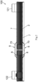
FIG. 1 is a schematic perspective view of a plate heat exchanger according to an embodiment of the present disclosure. -
FIG. 2 is a schematic cross-sectional view of the plate heat exchanger shown inFIG. 1 taken in a length direction. -
FIG. 3 is a schematic partial enlarged cross-sectional view of the plate heat exchanger shown inFIG. 2 . -
FIG. 4 is a schematic cross-sectional view of the plate heat exchanger shown inFIG. 1 taken in a width direction. -
FIG. 5 is a schematic partial enlarged cross-sectional view of the plate heat exchanger shown inFIG. 4 . -
FIG. 6A is a schematic perspective view of a sealing plate of the plate heat exchanger shown inFIG. 1 . -
FIG. 6B is a schematic front view of a sealing plate of the plate heat exchanger shown inFIG. 6A . -
FIG. 6C is a schematic cross-sectional view of a sealing plate of the plate heat exchanger shown inFIG. 6A . -
FIG. 7 is a schematic cross-sectional view of a plate heat exchanger taken in a width direction according to a variant of the embodiment shown inFIG. 1 . -
FIG. 8 is a schematic partial enlarged cross-sectional view of the plate heat exchanger shown inFIG. 7 . -
FIG. 9 is a schematic cross-sectional view of a plate heat exchanger taken in a length direction according to another embodiment of the present disclosure. -
FIG. 10 is a schematic partial enlarged cross-sectional view of the plate heat exchanger shown inFIG. 9 . -
FIG. 11 is a schematic partial enlarged cross-sectional view of a plate heat exchanger taken in a length direction according to another embodiment of the present disclosure. -
FIG. 12 is a schematic partial enlarged cross-sectional view of a plate heat exchanger taken in a length direction according to a variant of the embodiment shown inFIG. 11 . -
FIG. 13 is a schematic partial enlarged cross-sectional view of a plate heat exchanger taken in a length direction according to another variant of the embodiment shown inFIG. 11 . -
FIG. 14 is a schematic partial enlarged cross-sectional view of a plate heat exchanger taken in a length direction according to another variant of the embodiment shown inFIG. 11 . - The present invention will be described below in further detail in conjunction with the drawings and specific embodiments. Referring to
FIGS. 1 to 5 and7 to 14 , aplate heat exchanger 100 according to an embodiment of the present disclosure comprises: a plurality ofheat transfer plates 2; afirst fluid channel 3 and asecond fluid channel 4 formed between adjacentheat transfer plates 2 and fluidly isolated from each other; anupstream outlet port 51 anddownstream inlet port 52 formed in each of theheat transfer plates 2; and afluid communication device 6. Thefirst fluid channel 3 comprises a fluid channelupstream portion 31 and a fluid channeldownstream portion 32 that are separated from each other. Theupstream outlet port 51 is communicated to the fluid channel upstreamportion 31 of thefirst fluid channel 3, while thedownstream inlet port 52 is communicated to the fluid channeldownstream portion 32 of thefirst fluid channel 3. Theupstream outlet port 51 anddownstream inlet port 52 are fluidly communicated through thefluid communication device 6. According to the embodiment of the present disclosure, theplate heat exchanger 100 further comprises anend plate 7, which is disposed on an outer side of an outermostheat transfer plate 2U. Theplate heat exchanger 100 further comprises: afirst fluid inlet 111, afirst fluid outlet 112, a second fluid outlet 122 (for a counter flow evaporator), and a second fluid inlet 121 (for a counter flow evaporator). A first fluid such as refrigerant flows in thefirst fluid channel 3, while a second fluid such as water flows in thesecond fluid channel 4. The heat transfer plates 10 are stacked together, thereby alternately forming the firstfluid channel 3 and the secondfluid channel 4 in the stacking direction, or alternatively forming three or more fluid channels in the stacking direction. The first fluid channel is divided into the fluid channelupstream portion 31 and the fluid channeldownstream portion 32, while the second fluid channel is directly communicated. - Referring to
FIGS. 1 to 5 and7 to 14 , according to the embodiment of the present disclosure, the first fluid enters theplate heat exchanger 100 from the firstfluid inlet 111, then enters the fluid channelupstream portion 31 of the firstfluid channel 3, enters thefluid communication device 6 from theupstream outlet port 51, then enters thedownstream inlet port 52 from thefluid communication device 6, then enters the fluid channeldownstream portion 32 of the firstfluid channel 3, and finally flows out from the firstfluid outlet 112. The second fluid enters theplate heat exchanger 100 from the secondfluid inlet 121, then enters the second fluid channel, and finally flows out from the secondfluid outlet 122. - Referring to
FIGS. 3 to 5 , in the embodiment of the present disclosure, theend plate 7 is configured to have an end plateouter recess 70 that is recessed in a direction away from the outermostheat transfer plate 2U. The end plateouter recess 70 is configured to form achamber 60 as thefluid communication device 6 with a corresponding portion of the outermostheat transfer plate 2U. Referring toFIGS. 3 to 6C , in an example of the present disclosure, theplate heat exchanger 100 further comprises a sealingplate 8, wherein the sealingplate 8 comprises first andsecond openings annular protrusions second openings plate 8 is disposed between theend plate 7 and the outermostheat transfer plate 2U. According to the example of the present disclosure, an annularedge surface portion 82 of the sealingplate 8 on a side of the sealingplate 8 facing theend plate 7 is in contact with anannular surface portion 71 of theend plate 7 surrounding the end plateouter recess 70 to form a seal between the annularedge surface portion 82 of the sealingplate 8 and theannular surface portion 71 of theend plate 7, and the first and secondannular protrusions plate 8 are in contact with the firstannular surface portion 20A around theupstream outlet port 51 of the outermostheat transfer plate 2U and the secondannular surface portion 20B around thedownstream inlet port 52 of the outermostheat transfer plate 2U, respectively, to form a seal between theannular protrusion plate 8 and theannular surface portion heat transfer plate 2U, respectively (i.e., a seal between theannular protrusion 81A and theannular surface portion 20A, and a seal between theannular protrusion 81B and theannular surface portion 20B). The outermostheat transfer plate 2U may have a first heattransfer plate recess 21A and a second heattransfer plate recess 21B recessed towards their sides facing away from theend plate 7. The firstannular surface portion 20A of the outermostheat transfer plate 2U is disposed in a bottom 22A of the first heattransfer plate recess 21A of the outermostheat transfer plate 2U, and the secondannular surface portion 20B of the outermostheat transfer plate 2U is disposed in a bottom 22B of the second heattransfer plate recess 21B of the outermostheat transfer plate 2U. Theupstream outlet port 51 anddownstream inlet port 52 are respectively disposed in the bottom 22A of the first heattransfer plate recess 21A and the bottom 22B of the second heattransfer plate recess 21B of the outermostheat transfer plate 2U. The bottom 22A of the first heattransfer plate recess 21A and the bottom 22B of the second heattransfer plate recess 21B of the outermostheat transfer plate 2U respectively come into contact with the annular surface portions of an adj acentheat transfer plate 2N surrounding theupstream outlet port 51 and thedownstream inlet port 52 to form a seal, thereby isolating thesecond fluid passage 4 from theupstream outlet port 51 and thedownstream inlet port 52. As a result, theupstream outlet port 51 is only communicated to the fluid channelupstream portion 31 of the firstfluid channel 3, while thedownstream inlet port 52 is only communicated to the fluid channeldownstream portion 32 of the firstfluid channel 3. - In the embodiments shown in
FIGS. 2 to 6 , the sealingplate 8 comprises two openings corresponding to theupstream outlet port 51 and thedownstream inlet port 52 respectively. However, the sealingplate 8 may only comprise one opening, which corresponds to theupstream outlet port 51 or thedownstream inlet port 52. Specifically, the sealing plate comprises: an opening; an annular protrusion protruding surrounding the opening and protruding in a direction away from theend plate 7, wherein, the sealingplate 8 is disposed between theend plate 7 and the outermostheat transfer plate 2U. An annularedge surface portion 82 of the sealingplate 8 on the side of the sealingplate 8 facing theend plate 7 is in contact with anannular surface portion 71 of theend plate 7 surrounding the end plateouter recess 70 so as to form a seal between the annularedge surface portion 82 of the sealingplate 8 and theannular surface portion 71 of theend plate 7, and the annular protrusion of the sealingplate 8 is in contact with the annular surface portion around theupstream outlet port 51 anddownstream inlet port 52 of the outermostheat transfer plate 2U so as to form a seal between the annular protrusion of the sealingplate 8 and the annular surface portion of the outermostheat transfer plate 2U. The outermostheat transfer plate 2U may have a heat transfer plate recess that is recessed towards its side facing away from theend plate 7, and the annular surface portion of the outermostheat transfer plate 2U is disposed in the bottom of the heat transfer plate recess of the outermostheat transfer plate 2U. - Referring to
FIG. 3 , in the embodiment of the present disclosure, theend plate 7 is configured to further have astep portion 72 surrounding the end plateouter recess 70 and recessed in a direction away from the outermostheat transfer plat 2U. Theannular surface portion 71 of theend plate 7 surrounding the end plateouter recess 70 is disposed on thestep portion 72. The sealingplate 8 may be formed of metal and may be connected to theend plate 7 and the outermostheat transfer plate 2U through brazing. - Referring to
FIGS. 1 to 5 , according to an embodiment of the present disclosure, the end plate has an end plateouter recess 70, which may play a role in regulating a fluid distribution. By means of the end plateouter recess 70, a separate liquid collection box may be eliminated and a complexity of the brazing process may be reduced. - In addition, by using a single sealing plate, a number of parts is reduced and an assembly process is simplified. During the assembly process, the sealing plate may be self-adapted to the
step portion 72 of the end plate so as to achieve a precise positioning. At the same time, the sealing plate is made of composite bimetallic materials, such as, a copper is composited on both sides of a stainless steel sealing plate. After the copper is melted at a high temperature, the sealing plate is welded to the end plate and the outermost heat transfer plate respectively. As a result, a process of adding additional solder may be eliminated, thereby reducing a manufacturing complexity and shortening a manufacturing cycle. -
FIG. 7 is a schematic cross-sectional view of a plate heat exchanger taken in a width direction according to a variant of the embodiment shown inFIG. 1 .FIG. 8 is a schematic partial enlarged cross-sectional view of the plate heat exchanger shown inFIG. 7 . In the variant shown inFIGS. 7 and8 , theend plate 7 is in contact with the outermostheat transfer plate 2U, forming a seal and thus eliminating the sealing plate in the embodiments shown inFIGS. 1 to 6C . - Referring to
FIGS. 7 to 8 and in combination withFIGS. 2 and3 , in some embodiments of the present disclosure, theannular surface portion 71 of theend plate 7 surrounding the end plateouter recess 70 is in contact with theannular surface portion 20 of the outermostheat transfer plate 2U around theupstream outlet port 51 anddownstream inlet port 52 so as to form a seal between theannular surface portion 71 of theend plate 7 and theannular surface portion 20 of the outermostheat transfer plate 2U. The outermostheat transfer plate 2U is configured to have an annular heattransfer plate recess 23 around theupstream outlet port 51 anddownstream inlet port 52 and recessed in a direction away from theend plate 7, and the bottom 24 of the annular heattransfer plate recess 23 of the outermostheat transfer plate 2U is in contact with an adjacentheat transfer plate 2N so as to form a seal between the bottom 24 of the annular heattransfer plate recess 23 of the outermostheat transfer plate 2U and the adjacentheat transfer plate 2N. The heattransfer plate recess 23 of the outermostheat transfer plate 2U may be located on an outer side of theannular surface portion 20 of the outermostheat transfer plate 2U. Referring toFIGS. 7 to 8 , in other embodiments of the present disclosure, the heattransfer plate recess 23 comprises a plurality of discrete heat transfer plate recesses 23. Specifically, the outermostheat transfer plate 2U is configured to have a plurality of separated heat transfer plate recesses 23 around theupstream outlet port 51 anddownstream inlet port 52 and recessed in a direction away from theend plate 7, and thebottoms 24 of the plurality of separated heat transfer plate recesses 23 of the outermostheat transfer plate 2U are in contact with an adjacentheat transfer plate 2N. A number of the annular heattransfer plate recess 23 of the outermostheat transfer plate 2U may be one, and the one annular heattransfer plate recess 23 surrounds theupstream outlet port 51 and thedownstream inlet port 52. The number of the annular heat transfer plate recesses 23 may also be two, and the two annular heat transfer plate recesses 23 surround theupstream outlet port 51 and thedownstream inlet port 52, respectively. The heattransfer plate recess 23 of the outermostheat transfer plate 2U is located on an outer side of theannular surface portion 71 of the outermost heat transfer plate. It may be understood that the heattransfer plate recess 23 of the outermostheat transfer plate 2U may also be located on an inner side of theannular surface portion 71 of the outermost heat transfer plate. For example, a sealing connection between the outermostheat transfer plate 2U and the adjacentheat transfer plate 2N may be achieved by an interconnection of the annular portions around theupstream outlet port 51 and the downstream inlet port 52 (referring to a manner of connection of the adjacent heat transfer plates at thedownstream inlet port 52 inFIGS. 7 and8 , where the upper heat transfer plate is configured to have an annular recess surrounding the port, which is hermetically connected to the annular portion of the lower heat transfer plate). - Referring to
FIGS. 7 to 8 , according to an embodiment of the present disclosure, the end plate is configured to have an end plateouter recess 70, which may regulate the fluid distribution. Through the end plateouter recess 70, a separate liquid collection box may be eliminated, reducing the complexity of the brazing process. At the same time, by bending the outermostheat transfer plate 2U, theannular surface portion 20 of the outermostheat transfer plate 2U is in contact with the end plate, playing a role of sealing and eliminating a need for a separate sealing ring. - Referring to
FIGS. 9 to 10 , in an embodiment of the present disclosure, theend plate 7 is configured to have anopening 73. According to the embodiment of the present disclosure, theplate heat exchanger 100 further comprises achamber plate 9. Thechamber plate 9 comprises anannular plate portion 90 and thechamber plate recess 91. Theannular plate portion 90 may be located generally in one plane. Theannular plate portion 90 is disposed between theannular plate portion 74 of theend plate 7 surrounding theopening 73 of theend plate 7 and theannular surface portion 20 of the outermostheat transfer plate 2U around theupstream outlet port 51 anddownstream inlet port 52 so as to form a seal between theannular plate portion 74 of theend plate 7 and theannular plate portion 90 of thechamber plate 9, and a seal between theannular plate portion 90 of thechamber plate 9 and theannular surface portion 20 of the outermostheat transfer plate 2U. Thechamber plate recess 91 is configured to be recessed to the outer side of theend plate 7 through theopening 73 of theend plate 7 from theannular plate portion 90 of thechamber plate 9 towards a direction away from the outermostheat transfer plate 2U, and thechamber plate recess 91 and a portion of the outermostheat transfer plate 2U corresponding to thechamber plate recess 91 form achamber 60 as thefluid communication device 6. The outermostheat transfer plate 2U may have a heattransfer plate recess 23 that is recessed towards its side facing away from theend plate 7, and theannular surface portion 20 of the outermostheat transfer plate 2U is disposed in the bottom 24 of the heattransfer plate recess 23 of the outermostheat transfer plate 2U. The bottom of the heat transfer plate recess of the outermost heat transfer plate is in contact with the annular surface portions of the adjacent heat transfer plates around the upstream outlet port and downstream inlet port so as to form a seal, thereby isolating the second fluid channel from the upstream outlet port and downstream inlet port. Therefore, the upstream outlet port is only communicated to the fluid channel upstream portion of the first fluid channel, while the downstream inlet port is only communicated to the fluid channel downstream portion of the first fluid channel. - Referring to
FIGS. 9 to 10 , in an embodiment of the present disclosure, theend plate 7 is configured to have anopening 73. Theplate heat exchanger 100 further comprises achamber plate 9. Theannular plate portion 90 of thechamber plate 9 is sealed between the end plate and the outermost heat transfer plate, and at the same time, thechamber plate recess 91 of thechamber plate 9 forms achamber 60 as thefluid communication device 6 with the corresponding portion of the outermostheat transfer plate 2U. Therefore, it may regulate the fluid. A structure of the plate heat exchanger in accordance with this embodiment is compact, the two functions of the liquid collection box and the sealing ring are combined to one, thereby improving a manufacturing stability and shortening a production cycle of theplate heat exchanger 100. -
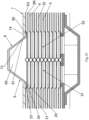
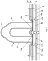
FIG. 11 is a schematic partial enlarged cross-sectional view of a plate heat exchanger taken in a length direction according to another embodiment of the present disclosure.FIG. 12 is a schematic partial enlarged cross-sectional view of a plate heat exchanger taken in a length direction according to a variant of the embodiment shown inFIG. 11 .FIG. 13 is a schematic partial enlarged cross-sectional view of a plate heat exchanger taken in a length direction according to another variant of the embodiment shown inFIG. 11 .FIG. 14 is a schematic partial enlarged cross-sectional view of a plate heat exchanger taken in a length direction according to another yet variant of the embodiment shown inFIG. 11 . - Referring to
FIG. 11 , in an embodiment of the present disclosure, theend plate 7 is configured to have a first throughhole 75A communicated to theupstream outlet port 51 and a second throughhole 75B communicated to thedownstream inlet port 52. The end plate 7 may have first and second end plate inner recesses 76A, 76B that are recessed to its side facing towards the outermost heat transfer plate 2U, and the first and second through holes 75A, 75B of the end plate 7 are respectively disposed in the bottom 77A of the first end plate inner recess 76A and the bottom 77B of the second end plate inner recess 76B of the end plate 7, a first annular bottom surface 78A of the bottom 77A of the first end plate inner recess 76A of the end plate 7 around the first through hole 75A and a second annular bottom surface 78B of the bottom 77B of the second end plate inner recess 76B of the end plate 7 around the second through hole 75B are in contact with the first annular surface portion 20A of the outermost heat transfer plate 2U around the upstream outlet port 51 and the second annular surface portion 20B of the outermost heat transfer plate 2U around the downstream inlet port 52, respectively, so as to form a seal between a first annular bottom surface 78A of the bottom 77A of the first end plate inner recess 76A of the end plate 7 and the first annular surface portion 20A of the outermost heat transfer plate 2U, and a seal between a second annular bottom surface 78B of the bottom 77B of the second end plate inner recess 76B of the end plate 7 and the second annular surface portion 20B of the outermost heat transfer plate 2U, respectively. The outermostheat transfer plate 2U is configured to have a first heattransfer plate recess 21A and a second heattransfer plate recess 21B, the firstannular surface portion 20A of the outermostheat transfer plate 2U is disposed in the bottom 22A of the first heattransfer plate recess 21A of the outermostheat transfer plate 2U, and the secondannular surface portion 20B of the outermostheat transfer plate 2U is disposed in the bottom 22B of the second heattransfer plate recess 21B of the outermostheat transfer plate 2U. Thefluid communication device 6 may comprise a communicatingtube 61 connected to theend plate 7 so as to connect the first throughhole 75A with the second throughhole 75B through the communicatingtube 61. The communicatingtube 61 is generally U-shaped. As shown inFIGS. 13 and14 , the communicatingtube 61 may have aprojection 63 protruding outward from itswall 62. Theprojection 63 of thewall 62 of the communicatingtube 61 may be located at a portion of thewall 62 of the communicatingtube 61 facing away from theend plate 7 or at another suitable position. Furthermore, althoughFIGS. 11 to 14 show that thefluid communication device 6 comprises the communicatingtube 61, thefluid communication device 6 may also comprise thechamber plate 9 as shown inFIGS. 9 and10 , and theannular plate portion 90 of thechamber plate 9 may cover an outer side surface of theend plate 7. - A difference between the variant shown in
FIG. 12 and the embodiment shown inFIG. 11 lies in that: in the embodiment shown inFIG. 11 , an end face of each of ends of the communicatingtube 61 is in contact with theend plate 7, while in the variant shown inFIG. 12 , each of the ends of the communicatingtube 61 is inserted into corresponding one of the through holes of theend plate 7. A difference between the variant shown inFIG. 13 and the embodiment shown inFIG. 11 lies in that: in the variant shown inFIG. 13 , thewall 62 of the communicatingtube 61 has theprojection 63 protruding outward. A difference between the variant shown inFIG. 14 and the embodiment shown inFIG. 11 lies in that: in the embodiment shown inFIG. 11 , the end face of each of ends of the communicatingtube 61 is in contact with theend plate 7, while in the variant shown inFIG. 14 , each of ends of the communicatingtube 61 is inserted into corresponding one of the through holes of theend plate 7, and thewall 62 of the communicatingtube 61 has theprojection 63 protruding outward. - Referring to
FIGS. 11 to 14 , in an embodiment of the present disclosure, the end plate is configured to have an end plate inner recess, whose bottom is in contact with the outermostheat transfer plate 2U to achieve a sealing function. At the same time, through holes are provided in the end plate inner recess of the end plate, and the through holes are connected to each other through a communicating tube (such as a tubeline that may be quickly installed, such as flame-brazed copper tube, etc.). The shape, length, and size of the tubeline may be adjusted according to the requirements of fluid distribution. Thewall 62 of the communicatingtube 61 may have theprojection 63 protruding outward, thereby enhancing a disturbance of the fluid. - Although the present disclosure has been described in conjunction with embodiments, it is not limited to the aforementioned embodiments. For example, some embodiments and some technical features in all the embodiments may be combined to form new embodiments.
Claims (14)
- A plate heat exchanger characterized by comprising:a plurality of heat transfer plates;a first fluid channel and a second fluid channel formed between adjacent heat transfer plates and fluidly isolated from each other, wherein the first fluid channel comprises a fluid channel upstream portion and a fluid channel downstream portion that are separated from each other;an upstream outlet port formed in each of the heat transfer plates and communicated to the fluid channel upstream portion of the first fluid channel, and a downstream inlet port formed in each of the heat transfer plates and communicated to the fluid channel downstream portion of the first fluid channel; anda fluid communication device, through which the upstream outlet port and the downstream inlet port are fluidly communicated with each other.
- The plate heat exchanger according to claim 1, characterized by further comprising:
an end plate disposed on an outer side of an outermost heat transfer plate and having an end plate outer recess that is recessed in a direction away from the outermost heat transfer plate, wherein the end plate outer recess is configured to form a chamber as the fluid communication device with a portion of the outermost heat transfer plate corresponding to the end plate outer recess. - The plate heat exchanger according to claim 2, characterized by further comprising:a sealing plate comprising:first and second openings; andfirst and second annular protrusions respectively surrounding the first and second openings and protruding towards their sides facing away from the end plate; andwherein the sealing plate is disposed between the end plate and the outermost heat transfer plate.
- The plate heat exchanger according to claim 3, characterized in that an annular edge surface portion of the sealing plate on a side of the sealing plate facing the end plate is in contact with an annular surface portion of the end plate surrounding the end plate outer recess so as to form a seal between the annular edge surface portion of the sealing plate and the annular surface portion of the end plate, and the first and second annular protrusions of the sealing plate are in contact with a first annular surface portion around the upstream outlet port of the outermost heat transfer plate and a second annular surface portion around the downstream inlet port of the outermost heat transfer plate, respectively, so as to form a seal between the first annular protrusion of the sealing plate and the first annular surface portion of the outermost heat transfer plate and a seal between the second annular protrusion of the sealing plate and the second annular surface portion of the outermost heat transfer plate, respectively.
- The plate heat exchanger according to claim 4, characterized in that the outermost heat transfer plate is configured to have first and second heat transfer plate recesses recessed towards its side facing away from the end plate, and the first annular surface portion of the outermost heat transfer plate is disposed in a bottom of the first heat transfer plate recess of the outermost heat transfer plate, and the second annular surface portion of the outermost heat transfer plate is disposed in a bottom of the second heat transfer plate recess of the outermost heat transfer plate.
- The plate heat exchanger according to claim 2, characterized by further comprising:a sealing plate comprising:an opening; andan annular protrusion protruding surrounding the opening and protruding towards its side facing away from the end plate; andwherein the sealing plate is disposed between the end plate and the outermost heat transfer plate.
- The plate heat exchanger according to claim 6, characterized in that an annular edge surface portion of the sealing plate on a side of the sealing plate facing the end plate is in contact with an annular surface portion of the end plate surrounding the end plate outer recess so as to form a seal between the annular edge surface portion of the sealing plate and the annular surface portion of the end plate, and the annular protrusion of the sealing plate is in contact with the annular surface portion around the upstream outlet port and downstream inlet port of the outermost heat transfer plate so as to form a seal between the annular protrusion of the sealing plate and the annular surface portion of the outermost heat transfer plate.
- The plate heat exchanger according to claim 7, characterized in that the outermost heat transfer plate is configured to have a heat transfer plate recess that is recessed towards its side facing away from the end plate, and the annular surface portion of the outermost heat transfer plate is disposed in the bottom of the heat transfer plate recess of the outermost heat transfer plate.
- The plate heat exchanger according to claim 3 or 6, characterized in that the end plate is configured to further have a step portion surrounding the end plate outer recess and recessed in a direction away from the outermost heat transfer plate, and the annular surface portion of the end plate surrounding the end plate outer recess is disposed on the step portion.
- The plate heat exchanger according to claim 3 or 6, characterized in that the sealing plate is formed of metal and connected to the end plate and the outermost heat transfer plate through brazing respectively.
- The plate heat exchanger according to claim 2, characterized in that the annular surface portion of the end plate surrounding the end plate outer recess is in contact with the annular surface portion of the outermost heat transfer plate around the upstream outlet port and downstream inlet port so as to form a seal between the annular surface portion of the end plate and the annular surface portion of the outermost heat transfer plate.
- The plate heat exchanger according to claim 11, characterized in that the outermost heat transfer plate is configured to have an annular heat transfer plate recess around the upstream outlet port and downstream inlet port and recessed in a direction away from the end plate, and a bottom of the annular heat transfer plate recess of the outermost heat transfer plate is in contact with an adjacent heat transfer plate so as to form a seal between the bottom of the annular heat transfer plate recess of the outermost heat transfer plate and the adjacent heat transfer plate.
- The plate heat exchanger according to claim 11, characterized in that the outermost heat transfer plate is configured to have a plurality of separated heat transfer plate recesses around the upstream outlet port and downstream inlet port and recessed in a direction away from the end plate, and bottoms of the plurality of separated heat transfer plate recesses of the outermost heat transfer plate are in contact with an adjacent heat transfer plate respectively.
- The plate heat exchanger according to claim 1, characterized by further comprising:an end plate disposed on an outer side of the outermost heat transfer plate and having an opening; anda chamber plate comprising:
an annular plate portion disposed between the annular plate portion of the end plate surrounding the opening of the end plate and the annular surface portion of the outermost heat transfer plate around the upstream outlet port and downstream inlet port so as to form seals between the annular plate portion of the end plate and the annular plate portion of the chamber plate, as well as between the annular plate portion of the chamber plate and the annular surface portion of the outermost heat transfer plate; anda chamber plate recess recessed to an outer side of the end plate through the opening of the end plate from the annular plate portion of the chamber plate in a direction away from the outermost heat transfer plate, the chamber plate recess and a portion of the outermost heat transfer plate corresponding to the chamber plate recess forming a chamber as the fluid communication device. 15. The plate heat exchanger according to claim 1, characterized by further comprising:
an end plate disposed on an outer side of the outermost heat transfer plate and having a first through hole communicated to the upstream outlet port and a second through hole communicated to the downstream inlet port, wherein the end plate is configured to have first and second end plate inner recesses that are recessed to its side facing towards the outermost heat transfer plate respectively, and the first and second through holes of the end plate are respectively disposed in a bottom of the first end plate inner recess and a bottom of the second end plate inner recess of the end plate, a first annular bottom surface of the bottom of the first end plate inner recess of the end plate around the first through hole and a second annular bottom surface of the bottom of the second end plate inner recess of the end plate around the second through hole are in contact with a first annular surface portion of the outermost heat transfer plate around the upstream outlet port and a second annular surface portion of the outermost heat transfer plate around the downstream inlet port, respectively, so as to form a seal between a first annular bottom surface of the bottom of the first end plate inner recess of the end plate and the first annular surface portion of the outermost heat transfer plate, and a seal between a second annular bottom surface of the bottom of the second end plate inner recess of the end plate and the second annular surface portion of the outermost heat transfer plate, respectively.
Applications Claiming Priority (1)
| Application Number | Priority Date | Filing Date | Title |
|---|---|---|---|
| CN202322097086.1U CN220524717U (en) | 2023-08-04 | 2023-08-04 | Plate heat exchanger |
Publications (3)
| Publication Number | Publication Date |
|---|---|
| EP4502520A1 true EP4502520A1 (en) | 2025-02-05 |
| EP4502520C0 EP4502520C0 (en) | 2026-03-04 |
| EP4502520B1 EP4502520B1 (en) | 2026-03-04 |
Family
ID=89930031
Family Applications (1)
| Application Number | Title | Priority Date | Filing Date |
|---|---|---|---|
| EP24187702.6A Active EP4502520B1 (en) | 2023-08-04 | 2024-07-10 | Plate heat exchanger |
Country Status (6)
| Country | Link |
|---|---|
| US (1) | US20250044034A1 (en) |
| EP (1) | EP4502520B1 (en) |
| CN (1) | CN220524717U (en) |
| ES (1) | ES3071555T3 (en) |
| MX (1) | MX2024008446A (en) |
| PL (1) | PL4502520T3 (en) |
Citations (4)
| Publication number | Priority date | Publication date | Assignee | Title |
|---|---|---|---|---|
| US20070125527A1 (en) * | 2003-06-25 | 2007-06-07 | Behr Gmgh & Co. Kg | Device for multi-stage heat exchange and method for producing one such device |
| US20150300743A1 (en) * | 2012-12-10 | 2015-10-22 | Danfoss Micro Channel Heat Exchange (Jiaxing) Co. Ltd. | Plate heat exchanger |
| KR20220007536A (en) * | 2020-07-10 | 2022-01-18 | 한온시스템 주식회사 | Heat exchanger |
| US20230109366A1 (en) * | 2020-03-30 | 2023-04-06 | Zhejiang Sanhua Automotive Components Co., Ltd. | Heat exchanger |
Family Cites Families (1)
| Publication number | Priority date | Publication date | Assignee | Title |
|---|---|---|---|---|
| JP2558019Y2 (en) * | 1992-09-24 | 1997-12-17 | カルソニック株式会社 | Oil cooler |
-
2023
- 2023-08-04 CN CN202322097086.1U patent/CN220524717U/en active Active
-
2024
- 2024-07-04 MX MX2024008446A patent/MX2024008446A/en unknown
- 2024-07-10 ES ES24187702T patent/ES3071555T3/en active Active
- 2024-07-10 EP EP24187702.6A patent/EP4502520B1/en active Active
- 2024-07-10 PL PL24187702.6T patent/PL4502520T3/en unknown
- 2024-07-29 US US18/787,007 patent/US20250044034A1/en active Pending
Patent Citations (4)
| Publication number | Priority date | Publication date | Assignee | Title |
|---|---|---|---|---|
| US20070125527A1 (en) * | 2003-06-25 | 2007-06-07 | Behr Gmgh & Co. Kg | Device for multi-stage heat exchange and method for producing one such device |
| US20150300743A1 (en) * | 2012-12-10 | 2015-10-22 | Danfoss Micro Channel Heat Exchange (Jiaxing) Co. Ltd. | Plate heat exchanger |
| US20230109366A1 (en) * | 2020-03-30 | 2023-04-06 | Zhejiang Sanhua Automotive Components Co., Ltd. | Heat exchanger |
| KR20220007536A (en) * | 2020-07-10 | 2022-01-18 | 한온시스템 주식회사 | Heat exchanger |
Also Published As
| Publication number | Publication date |
|---|---|
| CN220524717U (en) | 2024-02-23 |
| EP4502520C0 (en) | 2026-03-04 |
| ES3071555T3 (en) | 2026-06-24 |
| US20250044034A1 (en) | 2025-02-06 |
| MX2024008446A (en) | 2025-03-07 |
| PL4502520T3 (en) | 2026-07-13 |
| EP4502520B1 (en) | 2026-03-04 |
Similar Documents
| Publication | Publication Date | Title |
|---|---|---|
| EP2929273B1 (en) | Plate heat exchanger | |
| KR101292362B1 (en) | Plate Heat Exchanger | |
| CN102395853B (en) | Plate heat exchanger | |
| CN105579725A (en) | Heat exchanger with integrated co-axial inlet/outlet tube | |
| KR19990044058A (en) | Plate Heat Exchanger with Three Circuits | |
| KR102765868B1 (en) | Plate type heat exchanger | |
| CN100516752C (en) | Plate heat exchanger | |
| EP4502520B1 (en) | Plate heat exchanger | |
| EP4075086A1 (en) | Heat exchanger and assembly method therefor | |
| KR102189138B1 (en) | Laminated heat exchanger | |
| US10533804B2 (en) | Heat exchangers having high durability | |
| JP2016183833A (en) | Header plateless heat exchanger | |
| EP3467422B1 (en) | Heat exchanger assembly | |
| US12546544B2 (en) | Manifold for heat exchanger and heat exchanger | |
| CN104136872A (en) | Plate heat exchanger with improved strength in port area | |
| CN208936591U (en) | A microchannel heat exchanger and air conditioner | |
| CN116659275B (en) | Plate heat exchanger | |
| EP4343258A1 (en) | Heat exchanger and parting plate thereof | |
| CN117276144B (en) | Semiconductor water-cooling cavity structure and semiconductor processing equipment | |
| EP4343256B1 (en) | Heat exchanger | |
| CN116857996A (en) | Plate heat exchanger, distributor and plate for plate heat exchanger | |
| KR100514145B1 (en) | laminated type heat exchanger with a non-symmetrical hole for header | |
| KR200159658Y1 (en) | Heat exchanger | |
| JP6292844B2 (en) | Heat exchanger | |
| KR20250057413A (en) | Micro Channel Heat Exchanger and Manufacturing Method Thereof |
Legal Events
| Date | Code | Title | Description |
|---|---|---|---|
| PUAI | Public reference made under article 153(3) epc to a published international application that has entered the european phase |
Free format text: ORIGINAL CODE: 0009012 |
|
| STAA | Information on the status of an ep patent application or granted ep patent |
Free format text: STATUS: THE APPLICATION HAS BEEN PUBLISHED |
|
| AK | Designated contracting states |
Kind code of ref document: A1 Designated state(s): AL AT BE BG CH CY CZ DE DK EE ES FI FR GB GR HR HU IE IS IT LI LT LU LV MC ME MK MT NL NO PL PT RO RS SE SI SK SM TR |
|
| STAA | Information on the status of an ep patent application or granted ep patent |
Free format text: STATUS: REQUEST FOR EXAMINATION WAS MADE |
|
| 17P | Request for examination filed |
Effective date: 20250731 |
|
| GRAP | Despatch of communication of intention to grant a patent |
Free format text: ORIGINAL CODE: EPIDOSNIGR1 |
|
| STAA | Information on the status of an ep patent application or granted ep patent |
Free format text: STATUS: GRANT OF PATENT IS INTENDED |
|
| INTG | Intention to grant announced |
Effective date: 20251114 |
|
| GRAS | Grant fee paid |
Free format text: ORIGINAL CODE: EPIDOSNIGR3 |
|
| GRAA | (expected) grant |
Free format text: ORIGINAL CODE: 0009210 |
|
| STAA | Information on the status of an ep patent application or granted ep patent |
Free format text: STATUS: THE PATENT HAS BEEN GRANTED |
|
| AK | Designated contracting states |
Kind code of ref document: B1 Designated state(s): AL AT BE BG CH CY CZ DE DK EE ES FI FR GB GR HR HU IE IS IT LI LT LU LV MC ME MK MT NL NO PL PT RO RS SE SI SK SM TR |
|
| REG | Reference to a national code |
Ref country code: CH Ref legal event code: F10 Free format text: ST27 STATUS EVENT CODE: U-0-0-F10-F00 (AS PROVIDED BY THE NATIONAL OFFICE) Effective date: 20260304 Ref country code: GB Ref legal event code: FG4D |
|
| REG | Reference to a national code |
Ref country code: DE Ref legal event code: R096 Ref document number: 602024002959 Country of ref document: DE |
|
| REG | Reference to a national code |
Ref country code: IE Ref legal event code: FG4D |
|
| U01 | Request for unitary effect filed |
Effective date: 20260327 |
|
| U07 | Unitary effect registered |
Designated state(s): AT BE BG DE DK EE FI FR IT LT LU LV MT NL PT RO SE SI Effective date: 20260402 |
|
| REG | Reference to a national code |
Ref country code: ES Ref legal event code: FG2A Ref document number: 3071555 Country of ref document: ES Kind code of ref document: T3 Effective date: 20260624 |
|
| PG25 | Lapsed in a contracting state [announced via postgrant information from national office to epo] |
Ref country code: RS Free format text: LAPSE BECAUSE OF FAILURE TO SUBMIT A TRANSLATION OF THE DESCRIPTION OR TO PAY THE FEE WITHIN THE PRESCRIBED TIME-LIMIT Effective date: 20260604 |
|
| REG | Reference to a national code |
Ref country code: SK Ref legal event code: T3 Ref document number: E 48586 Country of ref document: SK |
|
| PGFP | Annual fee paid to national office [announced via postgrant information from national office to epo] |
Ref country code: PL Payment date: 20260612 Year of fee payment: 3 |
|
| PG25 | Lapsed in a contracting state [announced via postgrant information from national office to epo] |
Ref country code: GR Free format text: LAPSE BECAUSE OF FAILURE TO SUBMIT A TRANSLATION OF THE DESCRIPTION OR TO PAY THE FEE WITHIN THE PRESCRIBED TIME-LIMIT Effective date: 20260605 |
|
| U20 | Renewal fee for the european patent with unitary effect paid |
Year of fee payment: 3 Effective date: 20260608 |
|
| PG25 | Lapsed in a contracting state [announced via postgrant information from national office to epo] |
Ref country code: HR Free format text: LAPSE BECAUSE OF FAILURE TO SUBMIT A TRANSLATION OF THE DESCRIPTION OR TO PAY THE FEE WITHIN THE PRESCRIBED TIME-LIMIT Effective date: 20260304 |
|
| PGFP | Annual fee paid to national office [announced via postgrant information from national office to epo] |
Ref country code: SK Payment date: 20260612 Year of fee payment: 3 |