EP4502402A1 - Trennbare verbindungsvorrichtung, insbesondere für ein fluggerät und/oder raumfahrzeug - Google Patents
Trennbare verbindungsvorrichtung, insbesondere für ein fluggerät und/oder raumfahrzeug Download PDFInfo
- Publication number
- EP4502402A1 EP4502402A1 EP24190535.5A EP24190535A EP4502402A1 EP 4502402 A1 EP4502402 A1 EP 4502402A1 EP 24190535 A EP24190535 A EP 24190535A EP 4502402 A1 EP4502402 A1 EP 4502402A1
- Authority
- EP
- European Patent Office
- Prior art keywords
- parts
- connecting pin
- chamber
- plunger
- locking elements
- Prior art date
- Legal status (The legal status is an assumption and is not a legal conclusion. Google has not performed a legal analysis and makes no representation as to the accuracy of the status listed.)
- Pending
Links
Images


Classifications
-
- F—MECHANICAL ENGINEERING; LIGHTING; HEATING; WEAPONS; BLASTING
- F16—ENGINEERING ELEMENTS AND UNITS; GENERAL MEASURES FOR PRODUCING AND MAINTAINING EFFECTIVE FUNCTIONING OF MACHINES OR INSTALLATIONS; THERMAL INSULATION IN GENERAL
- F16B—DEVICES FOR FASTENING OR SECURING CONSTRUCTIONAL ELEMENTS OR MACHINE PARTS TOGETHER, e.g. NAILS, BOLTS, CIRCLIPS, CLAMPS, CLIPS OR WEDGES; JOINTS OR JOINTING
- F16B21/00—Means for preventing relative axial movement of a pin, spigot, shaft or the like and a member surrounding it; Stud-and-socket releasable fastenings
- F16B21/10—Means for preventing relative axial movement of a pin, spigot, shaft or the like and a member surrounding it; Stud-and-socket releasable fastenings by separate parts
- F16B21/16—Means for preventing relative axial movement of a pin, spigot, shaft or the like and a member surrounding it; Stud-and-socket releasable fastenings by separate parts with grooves or notches in the pin or shaft
- F16B21/165—Means for preventing relative axial movement of a pin, spigot, shaft or the like and a member surrounding it; Stud-and-socket releasable fastenings by separate parts with grooves or notches in the pin or shaft with balls or rollers
-
- B—PERFORMING OPERATIONS; TRANSPORTING
- B64—AIRCRAFT; AVIATION; COSMONAUTICS
- B64D—EQUIPMENT FOR FITTING IN OR TO AIRCRAFT; FLIGHT SUITS; PARACHUTES; ARRANGEMENT OR MOUNTING OF POWER PLANTS OR PROPULSION TRANSMISSIONS IN AIRCRAFT
- B64D1/00—Dropping, ejecting, releasing or receiving articles, liquids, or the like, in flight
- B64D1/02—Dropping, ejecting, or releasing articles
-
- B—PERFORMING OPERATIONS; TRANSPORTING
- B64—AIRCRAFT; AVIATION; COSMONAUTICS
- B64G—COSMONAUTICS; VEHICLES OR EQUIPMENT THEREFOR
- B64G1/00—Cosmonautic vehicles
- B64G1/22—Parts of, or equipment specially adapted for fitting in or to, cosmonautic vehicles
- B64G1/64—Systems for coupling or separating cosmonautic vehicles or parts thereof, e.g. docking arrangements
- B64G1/645—Separators
- B64G1/6455—Pyrotechnics; Using heat
-
- B—PERFORMING OPERATIONS; TRANSPORTING
- B64—AIRCRAFT; AVIATION; COSMONAUTICS
- B64G—COSMONAUTICS; VEHICLES OR EQUIPMENT THEREFOR
- B64G1/00—Cosmonautic vehicles
- B64G1/22—Parts of, or equipment specially adapted for fitting in or to, cosmonautic vehicles
- B64G1/64—Systems for coupling or separating cosmonautic vehicles or parts thereof, e.g. docking arrangements
- B64G1/645—Separators
- B64G1/6459—Fluid-actuated
-
- F—MECHANICAL ENGINEERING; LIGHTING; HEATING; WEAPONS; BLASTING
- F16—ENGINEERING ELEMENTS AND UNITS; GENERAL MEASURES FOR PRODUCING AND MAINTAINING EFFECTIVE FUNCTIONING OF MACHINES OR INSTALLATIONS; THERMAL INSULATION IN GENERAL
- F16B—DEVICES FOR FASTENING OR SECURING CONSTRUCTIONAL ELEMENTS OR MACHINE PARTS TOGETHER, e.g. NAILS, BOLTS, CIRCLIPS, CLAMPS, CLIPS OR WEDGES; JOINTS OR JOINTING
- F16B19/00—Bolts without screw-thread; Pins, including deformable elements; Rivets
- F16B19/04—Rivets; Spigots or the like fastened by riveting
- F16B19/08—Hollow rivets; Multi-part rivets
- F16B19/10—Hollow rivets; Multi-part rivets fastened by expanding mechanically
- F16B19/1027—Multi-part rivets
- F16B19/1036—Blind rivets
- F16B19/109—Temporary rivets, e.g. with a spring-loaded pin
-
- F—MECHANICAL ENGINEERING; LIGHTING; HEATING; WEAPONS; BLASTING
- F16—ENGINEERING ELEMENTS AND UNITS; GENERAL MEASURES FOR PRODUCING AND MAINTAINING EFFECTIVE FUNCTIONING OF MACHINES OR INSTALLATIONS; THERMAL INSULATION IN GENERAL
- F16B—DEVICES FOR FASTENING OR SECURING CONSTRUCTIONAL ELEMENTS OR MACHINE PARTS TOGETHER, e.g. NAILS, BOLTS, CIRCLIPS, CLAMPS, CLIPS OR WEDGES; JOINTS OR JOINTING
- F16B2200/00—Constructional details of connections not covered for in other groups of this subclass
- F16B2200/89—Use of a hydraulic action
-
- F—MECHANICAL ENGINEERING; LIGHTING; HEATING; WEAPONS; BLASTING
- F16—ENGINEERING ELEMENTS AND UNITS; GENERAL MEASURES FOR PRODUCING AND MAINTAINING EFFECTIVE FUNCTIONING OF MACHINES OR INSTALLATIONS; THERMAL INSULATION IN GENERAL
- F16B—DEVICES FOR FASTENING OR SECURING CONSTRUCTIONAL ELEMENTS OR MACHINE PARTS TOGETHER, e.g. NAILS, BOLTS, CIRCLIPS, CLAMPS, CLIPS OR WEDGES; JOINTS OR JOINTING
- F16B2200/00—Constructional details of connections not covered for in other groups of this subclass
- F16B2200/91—Use of a pneumatic action
Definitions
- the present invention relates to a device and a method for the separable connection of two parts, in particular for a flying and/or spacecraft such as an aircraft, a drone, a rocket or a missile for example.
- subassemblies In various fields, particularly in the aeronautics, aerospace and defense sector, it is particularly interesting to be able to link several subassemblies to each other and to be able to separate them at a desired time.
- aircraft, rockets or even satellites may have a main structure to which subassemblies such as boosters, stages, or weapons systems (missiles, bombs, etc.) are linked.
- subassemblies such as boosters, stages, or weapons systems (missiles, bombs, etc.) are linked.
- these subassemblies must be able to be detached and possibly ejected from the main structure at specific times.
- Pins separable or explosive nuts, jacks or retractors
- Pin or nut type devices make it possible to ensure the locking of an assembly and, under the action of an actuator, to release the parts of said assembly by removing the connection that locked them together. This connection can be removed by moving particular elements or by a pyrotechnic action such as an explosion of a nut or pin.
- Jack or retractor type devices generally provide a simple locking/unlocking function, by preventing or not two parts from separating using a retractable rod.
- Devices are also known for prestressing elements together to prevent their separation under known environments, for example elements subjected to vibrations or mechanical stresses.
- the object of the present invention is to propose a device for remedying the aforementioned drawbacks of existing devices. It relates to a separable connecting device for two parts.
- Said connecting device comprises a connecting pin configured to be able to be arranged, at least partially, in a first cavity of a first of said parts and in a second cavity of the second of said parts, said connecting pin being capable of holding said parts together securely and of separating them.
- the second cavity of the second part comprises the second chamber, said second chamber corresponding to a free space provided between an external wall of the connecting pin and an internal wall of the cavity.
- the connecting device comprises at least one clamping screw capable of being screwed into the connecting pin and of coming to bear on the second part, in the locked configuration, so as to obtain the predetermined force pressing the first part and the second part against each other, the tightening of the clamping screw making it possible to adjust said predetermined force.
- the connecting device comprises a nut configured to be screwed onto a thread of an extension of the connecting pin while bearing against the part, in the locked configuration, so as to obtain the predetermined force pressing the first part and the second part against each other, the tightening of the nut making it possible to adjust said predetermined force.
- the groove comprises a slope and the plunger comprises an inclined surface, said slope and said inclined surface being configured such that, in the locked configuration, the plunger acts on the locking elements, under the action of an elastic force exerted by the elastic element, so as to maintain said locking elements in the groove while transmitting said elastic force to one of the two parts, via said inclined surface and said slope, so as to press said parts against each other with the predetermined force, the characteristics of the elastic element making it possible to define said predetermined force.
- the fluid passage(s) between the first chamber and the second chamber are arranged so that, when the plunger moves under the effect of the pressure generated by the pressure generator, said plunger opens said fluid passages substantially at the same time as it releases the locking elements.
- the fluid passage(s) between the first chamber and the second chamber are arranged such that, upon movement of the plunger under the effect of the pressure generated by the pressure generator, said plunger opens said fluid passages after it has released the locking elements.
- the pressure is distributed in the second chamber after the connecting pin has been unlocked. This results in a retraction of the connecting pin that is moderately powerful and generates a moderate shock on the stop. This makes it possible to give a relatively gentle impulse to one of the two parts to separate them without risking damaging elements of either of said parts.
- the fluid passage(s) between the first chamber and the second chamber are arranged such that, when the plunger is moved under the effect of the pressure generated by the pressure generator, said plunger opens said fluid passages before it has released the locking elements.
- the locking elements can be made in different ways.
- the locking elements correspond to balls and, in the locked configuration, the connecting device is configured to obtain a point contact between said balls and one of the first and second parts capable of locking the connecting pin.
- the locking elements correspond to one of the following elements, rollers or barrels; and, in the locked configuration, the connecting device is configured to obtain a linear contact between said locking elements and one of the first and second parts capable of locking the connecting pin.
- the locking elements correspond to one of the following elements, wedges or keys; and, in the locked configuration, the connecting device is configured to obtain a surface contact between said locking elements and one of the first and second parts capable of locking the connecting pin.
- variants are available for obtaining a locking of the connecting pin with different contact surfaces.
- the pressure generator corresponds to one of the following fluid generating systems: a gas generating pyrotechnic cartridge, a fluid generating cartridge, a pneumatic system, a hydraulic system.
- At least one of the first and second parts comprises a movable plug configured to close, in the separation configuration, a mouth of the first cavity or of the second cavity, said plug comprising a face provided with an aerodynamic shape capable of matching an external surface of the first part or of the second part.
- the connecting device makes it possible to prevent one or the other of the two parts from having an open cavity after their separation. This makes it possible, in particular, to avoid drag effects in the case of a flying machine.
- the connecting pin is fully retracted within either the first cavity or the second cavity in the separation configuration.
- the connecting device prevents the connecting pin from protruding outside one or other of the parts after separation. In this way, it is not likely to come into contact with external elements. This also prevents drag effects in the case of a flying machine.
- the present invention also relates to a flying and/or spacecraft or a droppable object comprising at least two parts.
- said flying and/or spacecraft or the droppable object comprises at least one connecting device as described above for connecting said parts.
- it comprises a plurality of such connecting devices.
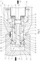
- the separable connecting device 1 (hereinafter device 1) for illustrating the invention is shown in particular embodiments of the figure 1 to the figure 5 .
- This device 1 is intended to securely connect at least two parts together.
- the term “part” may refer to single elements or to subassemblies comprising several elements.
- the device 1 may be adapted to attach a simple element to a support or to secure a more complex subassembly to a main structure.
- the device 1 is intended to allow, when desired, the detachment and separation of the two parts. It therefore allows not only to free the two parts from the interactions which hold them together, but also to move them away from each other after detachment.
- the device 1 is particularly suitable for applications in the fields of aeronautics, aerospace and defense. Examples clearly explaining the possible applications for the device 1 will be presented in the remainder of this description.
- a first embodiment of the device 1, shown in the figure 1 to the figure 4 is described in detail below. This is a preferred embodiment. However, the present invention is not limited to this first embodiment and may be implemented in various ways. Examples of other particular embodiments will be detailed later.
- the device 1 is configured to be able to securely connect a part 2 and a part 3 together and to be able to separate them at a desired time.
- part 2 is part of a primary set, namely a set that one wishes to keep after the separation of parts 2 and 3.
- part 3 it is part of a secondary set, namely a set that one wishes to separate at a particular time.
- the roles of parts 2 and 3 can be reversed.
- the device 1 comprises a connecting pin 4 configured to be able to be arranged, at least partially, in the parts 2 and 3.
- the connecting pin 4 comprises an end 5 configured to be able to be arranged in a cavity 6 of the part 2 and an end 7 configured to be able to be arranged in a cavity 8 of the part 3.
- the connecting pin 4 is thus arranged in the parts 2 and 3, it is capable of holding them together and then, when desired, of separating said parts 2 and 3.
- the device 1 is configured to be able to take several configurations in which the connecting pin 4 ensures the maintenance or separation of the parts 2 and 3.
- the connecting pin 4 holds the parts 2 and 3 together with a predetermined force pressing them against each other.
- the connecting pin 4 releases the parts 2 and 3 from the predetermined force and no longer holds them together.
- the connecting pin 4 is moved so as to initiate (or generate) a separation of the parts 2 and 3 moving them away from each other.
- the cavities 6 and 8 can be made directly in the parts 2 and 3. However, they can also be made in added parts, such as housings, which are fixed to said parts 2 and 3.
- the cavities 6 and 8 have, respectively, mouths 9 and 10 (visible on the figure 4 ) intended to be opposite each other when the parts 2 and 3 are held against each other.
- the mouth 10 of the part 3 has a bore 11 capable of guiding the connecting pin 4 in translation as explained below.
- the connecting pin 4 has a substantially cylindrical longitudinal shape. It is configured to be able to slide relative to the parts 2 and 3 in its longitudinal direction. To do this, the connecting pin 4 comprises a main section 12 extending longitudinally to its end 5. It also comprises a collar 13 at its end 7. The main section 12 is configured to be able to cooperate with the bore 11 formed at the mouth 10. The collar 13, for its part, is configured to be able to cooperate with a bore 14 arranged in the cavity 8 of the part 3. By “cooperate”, it is meant that the connecting pin 4 can slide in an adjusted manner in the bores 11 and 14. More precisely, the bore 11 is provided with an internal surface 15 capable of serving as a guide surface for the main section 12. Similarly, the bore 14 is provided with an internal surface 16 capable of serving as a guide surface for the collar 13.
- the connecting pin 4 may have various shapes capable of allowing translational movement of said connecting pin 4 relative to the parts 2 and 3.
- the connecting pin 4 may have a section shape other than a circular section, such as a square section or a rectangular section.
- the device 1 comprises a movable plunger 17 arranged in a cavity 18 formed inside the connecting pin 4.
- the plunger 17 corresponds to a rod provided, at one of its ends, with a head 19 and, at its other end, with a piston 20.
- the head 19 is arranged in a bore 21 of the cavity 18, on the side of the end 5 of the connecting pin 4.
- the piston 20 is arranged in a bore 22 of the cavity 18, on the side of the end 7 of the connecting pin 4.
- the head 19 and the piston 20 are able to cooperate, respectively, with the bores 21 and 22 so that the plunger 17 can slide longitudinally relative to the connecting pin 4.
- the device 1 comprises an elastic element 23 arranged in the connecting pin 4.
- the elastic element 23 is capable of exerting an elastic force on the plunger 17.
- the elastic element 23 is, in particular, capable of holding the plunger 17 in abutment towards the end 7 of the connecting pin 4 in the locked configuration.
- the elastic element 23 corresponds to a compression spring 23A (hereinafter spring 23A).
- spring 23A may be another usual element (for example a wedge) capable of exerting a force on the plunger 17.
- the spring 23A is arranged in the cavity 18 of the connecting pin 4 between a shoulder 24 of said cavity 18 and the piston 20 of the plunger 17.
- the spring 23A is configured to bear against the shoulder 24 at one of these ends and against the piston 20 at its other end so as to exert an elastic force on the plunger 17. This elastic force is capable of holding the plunger 17 towards the end 7 of the connecting pin 4 when the device 1 is in the locked configuration described below.
- the device 1 also comprises movable locking elements 25 capable of being moved to project out of the connecting pin 4 so as to block the latter in translation as described below.
- the locking elements 25 correspond to balls 25A. In other embodiments, they may be other usual elements capable of being moved so as to block the translation of the connecting pin 4.
- the balls 25A are housed in openings 26 of the connecting pin 4. These openings 26 correspond to through holes extending radially relative to the longitudinal direction of the connecting pin 4.
- the openings 26 open into the cavity 18, on the one hand, and outside the connecting pin 4 on the other hand. More particularly, the openings 26 are arranged so as to be opposite the head 19 of the plunger 17 so that the balls 25A can be in contact with said head 19.
- the connecting pin 4 may comprise usual elements for holding the balls 25A, for example a grid or a crimped elastic ring.
- the position of the balls 25A depends, among other things, on the portion of the head 19 facing the openings 26. Indeed, depending on the position of the plunger 17 (longitudinally relative to the connecting pin 4) a different portion of the head 19 faces the openings 26.
- One of these portions of the head 19 has a cylindrical surface 27 substantially of the same diameter as the bore 21 (in which the head 19 can slide). When the surface 27 faces the openings 26, the balls 25A are in contact with said surface 27 so as to be held to project out of the connecting pin 4 ( figure 1 ).
- Another portion of the head 19 has an inclined surface 28 of conical shape whose diameter decreases relative to that of the surface 27 to form a slope.
- the balls 25A can move towards the inside of the connecting pin 4 ( figure 3 And figure 4 ).
- the inclined surface 28 is configured so that the balls 25A can be accommodated in the openings 26 without protruding out of the connecting pin 4.
- the cavity 6 of the part 2 comprises a groove 29 capable of receiving the balls 25A when these protrude from the connecting pin 4.
- the balls 25A are held in the groove 29 by the head 19 of the plunger 17, they are capable of blocking a translation of the part 2 relative to the connecting pin 4. Indeed, in this position, the balls 25A are capable of preventing the part 2 from move longitudinally in a direction S1, illustrated by an arrow S1 of the figure 1 to the figure 4 .
- the connecting pin 4 is configured to be able to come to bear on the part 3, at its end 7, so as to block a translation of said part 3. More particularly, the collar 13 is configured to be able to come to bear against a shoulder 31. In this configuration, shown in the figure 1 , the connecting pin 4 is capable of preventing the part 3 from moving longitudinally in a direction S2, opposite to the direction S1 and illustrated by an arrow S2 of the figure 1 to the figure 5 .
- the support between the collar 13 and the shoulder 31 is obtained by indirect contact, in particular via adjustable elements specified below.
- this support between the collar 13 and the shoulder 31 can be obtained by direct contact.
- Parts 2 and 3, assembled with the connecting pin 4 as described above, are locked in translation relative to each other. However, for assembly reasons, there is a clearance in the connection between parts 2 and 3 and the connecting pin 4. This clearance is compensated by prestressing the assembly as described below.
- the device 1 may comprise a single clamping screw 32. However, it preferably comprises at least two clamping screws 32. In addition, the clamping screws 32 are arranged regularly around the collar 13. In this way, an overall support force of the connecting pin 4 on the part 3 is obtained which is homogeneous and balanced. This makes it possible, in particular, to increase the reliability of the device 1.
- the clamping screws 32 may be distributed heterogeneously around the collar 13. This makes it possible to concentrate the predetermined effort to prestress parts 2 and 3 at a particular location depending on the stresses to which parts 2 and 3 are likely to be subjected.
- the plunger 17 is arranged opposite the chamber 35 so that the piston 20 is able to form a hermetic (movable) wall between said chamber 35 and the rest of the cavity 18.
- the piston 20 is configured to be subjected to the action of the pressure generated in the chamber 35 so as to move the plunger 17 by compressing the spring 23A.
- the chamber 35 therefore has a variable volume which varies when the plunger 17 is moved. The movement and the particular positions taken by the plunger 17 will be detailed below in the description of the configurations of the device 1.
- the pressure generator 34 corresponds to a system for distributing a fluid (gas or liquid) capable of generating pressure using said fluid. It may be an internal system, namely directly arranged on the connecting pin 4, or a remote external system. For example, as shown in FIG. figure 1 to the figure 7 , the pressure generator 34 may correspond to a gas-generating pyrotechnic cartridge. It may also be a hydraulic or pneumatic system equipped with a pump or a pressurized gas bottle controlled by a pilot valve.
- the pressure generator 34 is configured to be able to be controlled by a control system or a conventional trigger system (not shown) on board the device 1.
- the control of the gas generator is independent of external conditions, which makes the device 1 particularly reliable.
- the pressure generator 34 is arranged on an insert 38 fixed to the end 7 of the connecting pin 4.
- the insert 38 corresponds to an interface part used to fix the pressure generator 34. It also serves as a stop for the piston 20 when the plunger 17 is held by the spring 23A in the locked configuration.
- other usual elements can be used as a stop for the piston 20, for example a stop ring or a particular shape of the plunger 17 and/or the connecting pin 4.
- the chamber 35 is formed partly in the cavity 18 and partly in the insert 38.
- the chamber 35 is capable of undergoing the pressure generated by the pressure generator 34 without being damaged and/or deformed by the latter.
- the pressure generator 34 comprises an orifice 39 opening into the chamber 35 so as to allow the fluid from the pressure generator 34 to enter the chamber 35 and generate pressure therein.
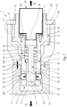
- Device 1 is configured to be able to successively take the locked configuration ( figure 1 ), the unlocked configuration ( figure 2 ) and the separation configuration ( figure 3 And figure 4 ) which are described below.
- the device 1 holds the parts 2 and 3 together by pressing them firmly against each other.
- the connecting pin 4 is locked between the parts 2 and 3. More precisely, it is arranged between the parts 2 and 3 so as to block them in translation. The translation of the part 2 is blocked in the direction S1 and the translation of the part 3 is blocked in the direction S2, as specified below.
- the parts 2 and 3 are pressed against each other so as to also block the rotation of one relative to the other.
- the plunger 17 is held by the spring 23A in a position P1 shown in the figure 1 .
- the piston 20 is in abutment against the insert 38.
- the surface 27 of the head 19 is opposite the openings 26 of the connecting pin 4.
- the balls 25A are therefore held in the groove 29 of the part 2 by the head 19 of the plunger 17, as illustrated by arrows E1 on the figure. figure 1 .
- Part 2 is therefore blocked in translation by the connecting pin 4 in the direction S1 and by part 3 in the direction S2.
- the clamping screws 32 bear against the shoulder 31 of the part 3.
- the part 3 is therefore blocked in translation by the connecting pin 4 in the direction S2 and by the part 2 in the direction S1. Furthermore, the tightening of the clamping screws 32 prestresses the parts 2 and 3 against each other so as to withstand external forces in translation and rotation.
- an external face 40 of the part 2 is pressed against an external face 41 of the part 3 with a predetermined force, represented by a double arrow F on the figure 1 .
- This predetermined force is obtained by tightening the clamping screws 32.
- tightening the clamping screws 32 generates a relative movement of the connecting pin 4 relative to the part 3.
- This relative movement of the connecting pin 4 relative to the part 3 causes the parts 2 and 3 to move closer together until the external faces 40 and 41 come into contact.
- tightening the clamping screws 32 makes it possible to define the force with which it is desired to press the parts 2 and 3 against each other.
- the device 1 releases the parts 2 and 3 from the predetermined force pressing them against each other.
- the connecting pin 4 is unlocked so as to no longer block the translation of the part 2 in the direction S1, as specified below.
- the plunger 17 is moved to a position P2 shown in the figure 2 .
- it is moved by a pressure generated by the pressure generator 34 in the chamber 35 so as to compress the spring 23A.
- the inclined surface 28 of the head 19 of the plunger 17 comes opposite the openings 26 allowing the balls 25A to be able to enter said openings.
- the position P2 corresponds to the position of the plunger 17 in which the balls 25A can enter sufficiently into the openings 26 to no longer block the translation of the part 2 in the direction S1.
- parts 2 and 3 are no longer subjected to the prestress pressing them against each other.
- they are no longer securely connected to each other since the connecting pin 4 no longer blocks the translation of one relative to the other.
- the unlocked configuration can be obtained at a particular desired time.
- the device 1 is configured so that the pressure generator 34 can be controlled by an order generated at a specific time.
- it is an order generated automatically, for example at a previously determined time or when certain conditions are met. It can also be an order generated by an operator.
- the device 1 separates the parts 2 and 3 by moving them away from each other.
- the connecting pin 4 is moved so as to come into contact against a stop 42 of the part 3.
- the shock generated by the contact of the connecting pin 4 against the stop 42 makes it possible to give an impulse to the part 3.
- This impulse is configured to initiate the separation of the parts 2 and 3.
- the plunger 17 is moved to a position P3 by the pressure generated by the pressure generator 34 in the chamber 35.
- the position P3 corresponds to a position of the plunger 17 in which the latter opens fluid passages 43.
- the fluid passages 43 correspond to through holes made radially in the connecting pin 4. They are arranged so as to open, at one of their ends, into the cavity 8 of the part 2 and, at their other end, into the cavity 18 of the connecting pin 4. More precisely, they open into the cavity 8 at the level of a second chamber 44.
- Room 44 shown in the figures 3 And 4 , corresponds to a free space provided between the external wall of the connecting pin 4 and the internal wall of the cavity 8.
- the chamber 44 is therefore arranged around the connecting pin 4. It is delimited longitudinally by a lateral face 45 of the collar 13 and an edge 46 of the bore 11.
- the connecting pin 4 is configured to hermetically close the chamber 44.
- the device 1 comprises seals (not shown) arranged in grooves 47 and 48 ( figure 3 And figure 4 ), respectively, on the connecting pin 4 and in the cavity 8.
- the piston 20 opens the fluid passages 43 so as to allow the fluid generating the pressure in the chamber 35 to pass into the chamber 44, as illustrated by arrows G on the figure 3 .
- the pressure generator 34 is therefore able to generate pressure in the chamber 44.
- the pressure generator 34 is configured to generate a pressure in the chamber 44 capable of moving the connecting pin 4 in the direction S2.
- the pressure in the chamber 44 is capable of producing a force on the lateral face 45 of the collar 13, oriented longitudinally in the direction S2.
- the connecting pin 4 is configured to transmit this force to the balls 25A so as to force them towards the inside of said connecting pin 4, as illustrated by arrows E2 on the figure 3 .
- the groove 29 has a shape tending to direct the balls 25A towards the inside of the connecting pin 4 when the latter exerts a force on the balls 25A in the direction S2.
- the balls 25A can enter by themselves towards the connecting pin 4 in the unlocked configuration.
- the device 1 is configured so that, when the pressure in the chamber 44 reaches a threshold pressure generating a so-called separation force on the collar 13, the balls 25A are moved inside the connecting pin 4, as shown in the figure 4 .
- the separation effort illustrated by arrows H on the figure 4 , corresponds to an effort making it possible to give a desired dynamic to the connecting pin 4.
- the separation effort makes it possible to overcome the friction between the balls 25A and the groove 29 in order to make them enter inside the openings 26 if necessary.
- it makes it possible to move the connecting pin 4, with more or less energy (in particular with more or less speed), until it generates a shock on contact with the stop 42.
- the stop 42 corresponds to an elastic ring 42A.
- This elastic ring 42A is arranged in a groove provided for this purpose in the cavity 8 of the part 2.
- the stop 42 can be made by other usual elements making it possible to create an obstacle for the connecting pin 4.
- it can be a particular shape provided on the part 3 or an added part such as a crown fixed on the part 3.
- parts 2 and 3 are no longer connected together and they are physically separated from each other.
- the contact of the connecting pin 4 on the elastic ring 42A creates a shock (more or less violent) giving an impulse to part 3 longitudinally in the direction S2.
- part 3 is moved away from part 2.
- This shock is, in particular, configured to move part 3 sufficiently away from part 2 so that the connecting pin 4 is completely out of the cavity 6.
- other forces may contribute to the separation of parts 2 and 3, for example aerodynamic forces or the inertia of parts 2 and 3.
- the connecting pin 4 is retracted into the part 3 after the separation of parts 2 and 3.
- the secondary assembly part 3 which keeps the connecting pin 4 and not the main assembly (part 2). This makes it possible to minimize the mass of the part of the device 1 which remains on part 2 after the separation of parts 2 and 3.
- the device 1 is configured so that the connecting pin 4 is fully retracted inside the cavity 8 after the separation of the parts 2 and 3.
- the connecting pin 4 does not comprise any part located outside the part 3 which would be likely to come into contact with external elements or to disturb an aerodynamic flow.
- This characteristic may, in particular, be important in the context of a separation of objects in an aerial environment or in weightlessness (or in pseudo-weightlessness).
- the device 1 comprises a movable plug 49 arranged in the cavity 6 of the part 2. It also comprises a compression spring represented schematically by a dotted line 50 on the figure 4 The spring is arranged between a bottom 51 and the plug 49 so as to exert an elastic force on said plug 49 by pushing it towards the mouth 9 of the cavity 6.
- the plug 49 is shown only on the figure 3 and the figure 4 .
- the device 1 is configured so that the connecting pin 4 bears against a face 52 of the stopper 49 so as to hold it towards the bottom 51 by compressing the spring.
- the device 1 is configured so that the connecting pin 4, moved in the direction S2, releases the plug 49. Under the action of the spring, the plug 49 is then able to be moved towards the mouth 9 so as to close it.
- the face 52 of the stopper 49 has an aerodynamic shape adapted to the external face 40 of the part 2. This face 52 is configured to match the shape of the external face 40 when the stopper closes the mouth 9.
- the cavity 6 of part 2 is closed by the plug 49. This makes it possible to prevent external elements from interfering with the cavity 6. Depending on the application considered, this can make it possible to limit drag effects likely to be generated at the cavity 6, or to prevent a thermal flow from entering the cavity 6 (for example for an atmospheric outlet or inlet).
- the plug 49 may be configured and/or arranged differently to close the cavity 6. In addition, it may be arranged on one or the other of the parts 2 and 3.
- the device 1 may also comprise a plug on each of the parts 2 and 3.
- the first three embodiments below concern variant embodiments for obtaining the predetermined force for prestressing the parts 2 and 3.
- the preload allowing parts 2 and 3 to be held pressed against each other is obtained using the spring 23A rather than with the clamping screws 32.
- this preload can be obtained by other usual elements such as spring washers.
- the groove 29 of the cavity 6 comprises a particular slope 53. Indeed, this slope 53 and the inclined surface 28 of the head 19 of the plunger 17 are configured to allow the spring 23A to hold the balls 25A in the groove 29 while exerting a force on the part 2, as detailed below.
- the device 1 according to this first embodiment is shown in the locked configuration on the figure 5 .
- the lateral face 45 of the collar 13 of the connecting pin 4 is in direct contact with the shoulder 31 of the part 3.
- the plunger 17 is held, under the action of an elastic force exerted by the spring 23A in the position P1 in which it holds the balls 25A in the groove 29.
- the position P1 corresponds to a position of the plunger 17 in which the inclined surface 28 of the head 19 is opposite the openings 26.
- the spring 23A exerts an elastic force on the plunger 17 which is transmitted to the balls 25A, via the inclined surface 28. This elastic force makes it possible to move the balls 25A in the groove 29 until contact with the slope 53.
- the slope 53 is configured to block the exit of the balls 25A.
- the slope 53 and the inclined surface 28 do not necessarily have the same inclination.
- the balls 25 are sufficiently moved in the groove 29 to lock the connecting pin 4 in translation.
- the balls 25A cannot come out further because they are blocked by the slope 53. Consequently, in this position, the balls 25A are able to transmit the elastic force of the spring 23A (itself transmitted by the plunger 17) to the part 2, as illustrated by arrows E3 on the figure 5 .
- the unlocked configuration and the separation configuration are similar to those described in the first embodiment presented above.
- the characteristics of the spring 23A namely its stiffness and its length, make it possible to define the predetermined force with which the parts 2 and 3 are pressed against each other.
- the locking of the connecting pin 4 ensuring the function of holding the parts 2 and 3 together and the pressing of the parts 2 and 3 against each other ensuring the prestressing function are obtained by the action of a single element, namely the spring 23A.
- the prestressing allowing the parts 2 and 3 to be pressed against each other is obtained by a different arrangement of the clamping screws 32.
- the device 1 comprises a rear flange 54 fixed to the part 3 on the side of the end 7 of the connecting pin 4 in the direction S2.
- the rear flange 54 comprises through holes for the clamping screws 32.
- the clamping screws 32 are arranged through the rear flange 54 so that their threaded end is screwed into the collar 13 of the connecting pin 4.
- the clamping screws 32 are supported against the rear flange 54 at their screw heads and screwed into the connecting pin 4. Tightening the clamping screws 32 allows the connecting pin 4 to be pulled in the direction S2. In the locked configuration shown in the figure 6 , the balls 25A are released. Consequently, tightening the clamping screws 32 makes it possible to press the parts 2 and 3 against each other with a desired predetermined force.
- the prestressing enabling the parts 2 and 3 to be pressed against each other is obtained using a nut 57 screwed onto the connecting pin 4.
- the connecting pin 4 has an extension 55 at its end 7.
- This extension 55 comprises a thread 56 for screwing the nut 57.
- the nut 57 is configured to come to bear against a bearing surface 58 of the part 3 when it is screwed onto the thread 56.
- the device 1 may comprise an intermediate part or a washer between the nut 57 and the part 3.
- the device 1 is configured so that, by screwing the nut 57 into the thread 56, it is possible to pull the connecting pin 4 in the direction S2 while bearing on the part 3.
- the balls 25A are released. Consequently, the nut 57 allows, by pulling the connecting pin 4, to press the parts 2 and 3 against each other with a desired predetermined force.
- the device 1 is configured so as to obtain a greater shock when the connecting pin 4 comes into contact with the elastic ring 42A.
- This powerful shock is obtained by generating a significant separation force to propel the connecting pin 4 against the elastic ring 42A.
- the device 1 is configured so that the plunger 17, when moved by the pressure generated by the pressure generator 34 in the chamber 35, reaches the position P3 before reaching the position P2.
- the fluid passages 43 are opened by the plunger 17 while the connecting pin 4 is still locked by the balls 25A. This allows the pressure in the chamber 44 to increase without the connecting pin 4 being moved. A greater separation force can therefore be obtained.
- the device 1 is configured so that the plunger 17 is moved to the position P2 when the pressure in the chamber 44 is capable of generating a separation force with a desired intensity.
- the connecting pin 4 is unlocked and can be moved against the elastic ring 42A by producing a sudden shock.
- the positions P2 and P3 of the plunger 17 can be configured to obtain a more or less rapid and brutal retraction of the connecting pin 4 generating a more or less powerful shock.
- one of the parts 2 and 3 may include equipment sensitive to shocks and/or strong vibrations, such as electronic equipment.
- the device 1 makes it possible to obtain a separable connection with a reduced shock level, so that this equipment is not damaged or disturbed when the parts 2 and 3 are separated.
- the parts 2 and 3 are insensitive to shocks and/or vibrations, it is possible to provide a device 1 configured to separate the parts 2 and 3 by moving them more sharply and more quickly away from each other. The separation obtained by such a device 1 would, however, remain less brutal than the known separations by detonation (for example by explosive nut).
- the locking elements 25 correspond to other usual elements than the balls 25A.
- the locking elements 25 correspond to rollers or barrels.
- the groove 29 has a shape adapted so that, in the locked configuration, the rollers or barrels have a linear support in said groove 29.
- the locking elements 25 correspond to wedges or keys.
- the groove 29 has a shape adapted so that, in the locked configuration, the wedges or keys have a surface support in said groove 29.
- the device 1 as described above is capable of implementing a method of connecting and separating (hereinafter method) the parts 2 and 3.
- method is implemented by a single device 1.
- the method can be implemented by a plurality of devices 1.
- the method is intended to allow the separation of parts 2 and 3 securely connected together by the device 1 in the locked configuration. To do this, the method comprises an unlocking step and a separation step implemented successively.
- the method may comprise a connecting step.
- This connecting step consists of connecting the parts 2 and 3 together using a device 1.
- parts 2 and 3 are brought together so that cavities 6 and 8 are facing each other.
- Connecting pin 4 is then inserted into cavity 8 of part 3 and then slid in direction S1 so that its end 5 is housed in cavity 6 of part 2.
- plunger 17 is manually moved so that balls 25A can be entered into openings 26.
- Connecting pin 4 can then be slid in direction S1 until openings 26 are facing groove 29.
- plunger 17 is released and, under the action of spring 23A, it moves and holds balls 25A in groove 29.
- the clamping screws 32 are screwed in to come into contact with the shoulder 31 of the part 3.
- the connecting pin 4 is then pulled in the direction S2, driving the part 2, via the balls 25A, against the part 3.
- a suitable tightening of the clamping screws 32 is carried out to obtain a desired predetermined force pressing the parts 2 and 3 against each other.
- the parts 2 and 3 are securely connected together with a prestress.
- the unlocking step is first implemented.
- This step consists of controlling the pressure generator 34 so that it generates a pressure in the chamber 35.
- the pressure generator 34 is controlled by an automatically generated order.
- the pressure generated in the chamber 35 then moves the plunger 17 to the position P2 which releases the balls 25A.
- the release of the balls 25A allows them to enter the openings 26 to unlock the connecting pin 4.
- the separation step is implemented after the unlocking step.
- the plunger 17 is moved to the position P3 by the pressure generated in the chamber 35.
- the plunger 17 then opens the fluid passages 43 between the chamber 35 and the chamber 44.
- the fluid generating the pressure in the chamber 35 is thus able to pass into the chamber 44 to generate pressure there.
- the pressure in the chamber 44 moves the connecting pin 4 in the direction S2 since the latter is now unlocked.
- the connecting pin 4 under the action of the pressure in the chamber 44, is moved until it comes into contact against the elastic ring 42A. The shock produced by this contact generates the separation of the parts 2 and 3 by moving the part 3 away from the part 2.
- the method is intended to obtain a more marked separation of parts 2 and 3.
- the unlocking step and the separation step vary as specified below.
- the unlocking step consists of generating pressure in the chamber 44 before unlocking the connecting pin 4.
- the pressure generator 34 is controlled to generate pressure in the chamber 35.
- the pressure in the chamber 35 moves the plunger 17 to the position P3 in which it opens the fluid passages 43.
- the fluid in the chamber 35 therefore passes into the chamber 44 to generate pressure there. Since the connecting pin 4 is still locked, it is not moved by the pressure in the chamber 44. Consequently, the pressure in the chamber 44 increases.
- the pressure in the chamber 35 increases so as to move the plunger 17 into the position P2.
- the plunger 17 releases the balls 25A which unlock the connecting pin 4.
- the connecting pin 4 is then propelled quickly and abruptly against the elastic ring 42A. Indeed, as the pressure in the chamber 44 has been able to increase, the separation force propelling the connecting pin 4 is greater. Consequently, the impact against the elastic ring 42A is also greater.
- the device 1 as described above is a compact device suitable for a wide variety of applications. Indeed, it has a simple architecture and kinematics that can be adapted to many systems, including flying and/or spacecraft such as rockets or weapon systems such as missiles. In particular, it can be integrated into a craft independently, i.e. it only requires one command to operate.
- device 1 is a single-use device (“one shot” in English) that can be quickly controlled and that can be fully embedded. In addition, it can be easily rearmed by an external action, in particular manually.
- the device 1 may be intended to connect and separate elements of the rocket in flight.
- rockets generally comprise elements such as stages, boosters and/or fairings which are useful only during take-off and/or during the first phases of flight. Once they are no longer useful, these elements must be detached in flight in order to lighten the rocket.
- the device 1 may be intended to link and separate elements such as a booster in flight. It may also be intended to link and separate a missile and a container or a missile and a firing interface on the ground or in flight.
Landscapes
- Engineering & Computer Science (AREA)
- Aviation & Aerospace Engineering (AREA)
- General Engineering & Computer Science (AREA)
- Remote Sensing (AREA)
- Mechanical Engineering (AREA)
- Hydraulic Clutches, Magnetic Clutches, Fluid Clutches, And Fluid Joints (AREA)
- Mutual Connection Of Rods And Tubes (AREA)
- Snaps, Bayonet Connections, Set Pins, And Snap Rings (AREA)
Applications Claiming Priority (1)
| Application Number | Priority Date | Filing Date | Title |
|---|---|---|---|
| FR2308356A FR3151840B1 (fr) | 2023-08-04 | 2023-08-04 | Dispositif de liaison séparable, en particulier pour un engin volant et/ou spatial |
Publications (1)
| Publication Number | Publication Date |
|---|---|
| EP4502402A1 true EP4502402A1 (de) | 2025-02-05 |
Family
ID=88964988
Family Applications (1)
| Application Number | Title | Priority Date | Filing Date |
|---|---|---|---|
| EP24190535.5A Pending EP4502402A1 (de) | 2023-08-04 | 2024-07-24 | Trennbare verbindungsvorrichtung, insbesondere für ein fluggerät und/oder raumfahrzeug |
Country Status (3)
| Country | Link |
|---|---|
| EP (1) | EP4502402A1 (de) |
| FR (1) | FR3151840B1 (de) |
| WO (1) | WO2025031801A1 (de) |
Citations (2)
| Publication number | Priority date | Publication date | Assignee | Title |
|---|---|---|---|---|
| GB971537A (en) * | 1959-12-11 | 1964-09-30 | Aerpat Ag | Improvements in or relating to quick release fasteners |
| WO2019014293A2 (en) * | 2017-07-12 | 2019-01-17 | Oakland University | MECHANICAL CONNECTOR WITH QUICK DISCONNECT |
-
2023
- 2023-08-04 FR FR2308356A patent/FR3151840B1/fr active Active
-
2024
- 2024-07-24 WO PCT/EP2024/070989 patent/WO2025031801A1/fr active Pending
- 2024-07-24 EP EP24190535.5A patent/EP4502402A1/de active Pending
Patent Citations (2)
| Publication number | Priority date | Publication date | Assignee | Title |
|---|---|---|---|---|
| GB971537A (en) * | 1959-12-11 | 1964-09-30 | Aerpat Ag | Improvements in or relating to quick release fasteners |
| WO2019014293A2 (en) * | 2017-07-12 | 2019-01-17 | Oakland University | MECHANICAL CONNECTOR WITH QUICK DISCONNECT |
Also Published As
| Publication number | Publication date |
|---|---|
| FR3151840B1 (fr) | 2025-06-20 |
| WO2025031801A1 (fr) | 2025-02-13 |
| FR3151840A1 (fr) | 2025-02-07 |
Similar Documents
| Publication | Publication Date | Title |
|---|---|---|
| EP2620738B1 (de) | Ansteuerungsteil fur Munition | |
| CA1332537C (fr) | Engin aerien pourvu d'au moins un propulseur largable | |
| EP3519300B1 (de) | Verbindungsvorrichtung für punktuelle provisorische verbindungen | |
| EP0061398B1 (de) | Verfahren und Vorrichtung zum Speichern und Ausklinken von zylindrischen Objekten in Fahrzeugen | |
| WO2023166389A1 (fr) | Dispositif de lancement pneumatique d'un drone | |
| EP0488872B1 (de) | Vorrichtung zum zeitweisen Halten eines Objekts an einem Träger mit einer einteiligen Halterungshülse | |
| EP4502402A1 (de) | Trennbare verbindungsvorrichtung, insbesondere für ein fluggerät und/oder raumfahrzeug | |
| EP4193113B1 (de) | Projektilabschussvorrichtung | |
| EP2964947B1 (de) | Vorrichtung zur modulation eines gasausstossabschnitts | |
| EP4560253B1 (de) | System und verfahren zum ein- und auswerfen einer schleudervorrichtung | |
| EP3589550B1 (de) | Verfahren und vorrichtung zum verbinden und linearen trennen zweier zusammengehaltener elemente | |
| WO2017037246A1 (fr) | Procede de liaison et de separation lineaire de deux elements | |
| EP0597750B1 (de) | Gerät zum Halten und Auswerfen eines Objekts bezüglich eines Trägers, mit einer kontrollierten Ablauffolge | |
| FR2902472A1 (fr) | Dispositif de jonction mecanique temporaire d'un objet sur une structure | |
| FR3024709A1 (fr) | Procede et systeme pour le transfert d'un satellite d'une orbite initiale dans une orbite de mission | |
| EP4461657B1 (de) | Verbesserte vorrichtung zum starten einer drohne durch federschub, verfahren zum starten von drohnen mit dieser vorrichtung | |
| EP2623918B1 (de) | Pneumatische abschussvorrichtung | |
| EP3891375B1 (de) | Festkörper-booster für eine abschussvorrichtung | |
| FR2876985A1 (fr) | Dispositif de jonction temporaire d'un objet sur une structure. | |
| WO2025109260A1 (fr) | Dispositif de vessie à pression de gaz et ensemble d'éjection | |
| FR2693978A1 (fr) | Dispositif de maintien puis d'éjection d'une charge utile à l'aide d'un module d'espacement. | |
| FR2791130A1 (fr) | Engin muni d'un ejecteur pyrotechnique largable |
Legal Events
| Date | Code | Title | Description |
|---|---|---|---|
| PUAI | Public reference made under article 153(3) epc to a published international application that has entered the european phase |
Free format text: ORIGINAL CODE: 0009012 |
|
| STAA | Information on the status of an ep patent application or granted ep patent |
Free format text: STATUS: THE APPLICATION HAS BEEN PUBLISHED |
|
| AK | Designated contracting states |
Kind code of ref document: A1 Designated state(s): AL AT BE BG CH CY CZ DE DK EE ES FI FR GB GR HR HU IE IS IT LI LT LU LV MC ME MK MT NL NO PL PT RO RS SE SI SK SM TR |
|
| STAA | Information on the status of an ep patent application or granted ep patent |
Free format text: STATUS: REQUEST FOR EXAMINATION WAS MADE |
|
| 17P | Request for examination filed |
Effective date: 20250626 |