EP4502204A1 - Sliding material - Google Patents
Sliding material Download PDFInfo
- Publication number
- EP4502204A1 EP4502204A1 EP23780881.1A EP23780881A EP4502204A1 EP 4502204 A1 EP4502204 A1 EP 4502204A1 EP 23780881 A EP23780881 A EP 23780881A EP 4502204 A1 EP4502204 A1 EP 4502204A1
- Authority
- EP
- European Patent Office
- Prior art keywords
- intermetallic compound
- based intermetallic
- hardness
- sliding material
- gpa
- Prior art date
- Legal status (The legal status is an assumption and is not a legal conclusion. Google has not performed a legal analysis and makes no representation as to the accuracy of the status listed.)
- Pending
Links
Images


Classifications
-
- F—MECHANICAL ENGINEERING; LIGHTING; HEATING; WEAPONS; BLASTING
- F16—ENGINEERING ELEMENTS AND UNITS; GENERAL MEASURES FOR PRODUCING AND MAINTAINING EFFECTIVE FUNCTIONING OF MACHINES OR INSTALLATIONS; THERMAL INSULATION IN GENERAL
- F16C—SHAFTS; FLEXIBLE SHAFTS; ELEMENTS OR CRANKSHAFT MECHANISMS; ROTARY BODIES OTHER THAN GEARING ELEMENTS; BEARINGS
- F16C33/00—Parts of bearings; Special methods for making bearings or parts thereof
- F16C33/02—Parts of sliding-contact bearings
- F16C33/04—Brasses; Bushes; Linings
- F16C33/06—Sliding surface mainly made of metal
- F16C33/12—Structural composition; Use of special materials or surface treatments, e.g. for rust-proofing
- F16C33/121—Use of special materials
-
- C—CHEMISTRY; METALLURGY
- C22—METALLURGY; FERROUS OR NON-FERROUS ALLOYS; TREATMENT OF ALLOYS OR NON-FERROUS METALS
- C22C—ALLOYS
- C22C9/00—Alloys based on copper
- C22C9/04—Alloys based on copper with zinc as the next major constituent
-
- F—MECHANICAL ENGINEERING; LIGHTING; HEATING; WEAPONS; BLASTING
- F16—ENGINEERING ELEMENTS AND UNITS; GENERAL MEASURES FOR PRODUCING AND MAINTAINING EFFECTIVE FUNCTIONING OF MACHINES OR INSTALLATIONS; THERMAL INSULATION IN GENERAL
- F16C—SHAFTS; FLEXIBLE SHAFTS; ELEMENTS OR CRANKSHAFT MECHANISMS; ROTARY BODIES OTHER THAN GEARING ELEMENTS; BEARINGS
- F16C33/00—Parts of bearings; Special methods for making bearings or parts thereof
Definitions
- the present invention relates to a sliding material.
- Patent Literature 1 discloses an abrasion-resistant copper alloy, wherein the weight ratio to Fe and Mn is from 0.3 to 14 and the content is 1 to 15% by weight. Patent Literature 1 states that this ternary compound has higher abrasion resistance than conventional ones containing Mn 5 Si 3 and/or Fe 3 Si. Patent Literature 1 merely discloses that the addition of Cr has a dispersion effect.
- Patent Literature 2 discloses manganese silicide in brass alloy.
- Cr, Zr, or compounds thereof act as a nucleating agent for the silicide deposit, and the addition thereof suppresses the eutectic fine deposition of silicides. That is, Patent Literature 2 discloses that the addition of Cr or Zr in a minute amount enables changing the precipitation morphology of manganese silicide.
- Patent Literature 3 discloses additives such as Ti, Zr, V, and Cr, contributing to the micronization of the structure and the grain boundary strengthening as selective elements in a sintered material comprising a brass alloy containing Cu, Zn, Al, and Si as base metals. Since this sintered material utilizing surface pores is produced unlike ingot material without a step of completely melting the additive components to form alloy, even the sintered material containing the same components exhibits heterogeneous structures unlike the structure of ingot material.
- Patent Literature 4 discloses a material wherein a brass matrix is limited to the ⁇ -phase, the amounts of Fe, Mn, and Si added are limited on the assumption that Fe-Mn-Si-based intermetallic compounds having compositions of Mn 5 Si 3 and Fe 3 Si, and the area rate of the compounds is 3 to 20%.
- Patent Literature 5 discloses a substance, comprising Fe-based silicides such as a Fe-Cr-Si-based intermetallic compound, wherein the brass matrix is limited to the ⁇ -phase, but detail of the compound is not clarified.
- Mn-Si-based intermetallic compounds or improved Mn-Fe-Si-based intermetallic compounds have been increasingly utilized in brass matrices to contribute to improvement in abrasion resistance. Effects such as the precise chemical compositions, the precipitation morphologies, and the hardness of the intermetallic compounds on the friction and abrasion have not, however, been fully inspected.
- the present invention has been completed to solve such a conventional problem, and an object thereof is to provide a sliding material having improved sliding characteristics.
- the present invention is a sliding material, comprising a substrate comprising brass alloy and a Cr-Fe-Si-based intermetallic compound comprised in the substrate, wherein the nanoindentation hardness of regions wherein the Cr-Fe-Si-based intermetallic compound precipitated is 20 GPa or more and 28 GPa or less.
- the present invention enables providing a sliding material having improved sliding characteristics.
- Figure 1 is a schematic diagram showing a sectional structure of a sliding material 1 of the embodiment.
- Figure 1 shows a three-dimensional structure of an intermetallic compound viewed from a cross section perpendicular to a sliding surface 1A.
- the sliding material 1 comprises a substrate (matrix) 2 and a Cr-Fe-Si-based intermetallic compound 3.
- the substrate 2 comprises brass alloy.
- the substrate 2 imparts a shape and mechanical strength depending on its application to the sliding material 1.
- the sliding material 1 of the embodiment contains (Cr,Fe) 3 Si as a Cr-Fe-Si-based intermetallic compound 3, containing Cr as the main component.
- the Cr-Fe-Si-based intermetallic compound 3 representatively has a structure of (Cr 0.85 Fe 0.15 ) 3 Si.
- the Cr-Fe-Si-based intermetallic compound 3 has a composition of Cr Fe, and Si.
- the Cr-Fe-Si-based intermetallic compound 3 of the embodiment has a structure of (Cr,Fe) 3 Si.
- Each Cr-Fe-Si-based intermetallic compound 3 has roundish outer shape with curved surfaces.
- Numerous Cr-Fe-Si-based intermetallic compounds 3 contained in the substrate 2 are bound to each other to have a spatial structure in which the numerous Cr-Fe-Si-based intermetallic compounds 3 are connected.
- the sliding material of the present embodiment has regions with a nanoindentation hardness of 20 GPa or more and 28 GPa or less in which the Cr-Fe-Si-based intermetallic compound 3 precipitated. The definition and the measurement method of the hardness of the Cr-Fe-Si-based intermetallic compound 3 will be described below.
- the binding ratio between the atoms in the Cr-Fe-Si-based intermetallic compound 3 was calculated from the composition in % by atom determined by point analysis using SEM-EDS to identify the compound and determine the binding rates of the atoms.
- the binding ratio of Mn to Si of 5:3 the binding ratio of Mn to Si of 5:3, the manganese silicide proves to be a compound with a chemical structure of Mn 5 Si 3 .
- intermetallic compound components are notated in descending order of content in the same way as in the notation of general alloy components, and for example, an intermetallic compound is notated as a Mn-Si-based intermetallic compound.
- the Cr-Fe-Si-based intermetallic compound 3 indicates that a compound comprises Cr as the main component, Fe, and Si.
- Intermetallic compounds were often evaluated exclusively based on the cross-sectional shape in the past. In the case of friction and abrasion, the three-dimensional precipitation morphology of the compounds however needs to be comprehended in response to the process of abrasion progress.
- the present inventors have developed a corrosion method for dissolving the brass substrate 2 to leave only the Cr-Fe-Si-based intermetallic compound 3.
- the three-dimensional precipitation morphology of the Cr-Fe-Si-based intermetallic compound 3 can therefore be observed by SEM (secondary electron image).
- the spatial structure of the Cr-Fe-Si-based intermetallic compound 3 can be comprehended by this method.
- the morphologies of the intermetallic compounds were compared to inspect the effects thereof on friction and abrasion.
- the hardness of the Cr-Fe-Si-based intermetallic compound 3 can be measured with a nanoindenter.
- the hardness is measured with a nanoindenter in accordance with "ISO 14577-1 Metallic materials - Instrumented indentation test for hardness and materials parameters-" and the annex thereof, "Annex A (normative) Materials parameters determined from the force/indentation depth data set”.
- the conditions for measuring the nanoindentation hardness are as follows.
- HIT HIT8 ⁇ 10 ⁇ 4 / 1 / 0.4 / 1 (Notes: ISO 14577-1 Annex A)
- the measurement procedure and the method for determining the nanoindentation hardness of the Cr-Fe-Si-based intermetallic compound 3 are as follows.
- the regions A of the substrate 2 have a nanoindentation hardness of around 4 GPa.
- the precipitation of the Cr-Fe-Si-based intermetallic compound 3 makes the boundary regions B between the substrate 2 and the Cr-Fe-Si-based intermetallic compound 3 harder than the substrate 2, and increases the hardness rapidly from the near vicinity of the substrate 2.
- the nanoindentation hardness in the central portion is comparatively flat, and is 19.5 GPa or more and 24.4 GPa or less in Figure 2 .
- the nanoindentation hardness can be obtained as only discrete values by this measurement method.
- the regions C in which the hardness was flat and high were therefore considered to be regions in which the Cr-Fe-Si-based intermetallic compound 3 precipitated.
- the nanoindentation hardness of the regions C was defined as the hardness of the Cr-Fe-Si-based intermetallic compound 3.
- the boundary regions B are defined as portions satisfying the following condition: H n + 1 ⁇ H n > 6.0 GPa wherein H n is defined as the nanoindentation hardness at a grid point, and H n+1 is defined as the nanoindentation hardness at an adjacent grid point 1.5 ⁇ m separate therefrom.
- H n is defined as the nanoindentation hardness at a grid point
- H n+1 is defined as the nanoindentation hardness at an adjacent grid point 1.5 ⁇ m separate therefrom.
- the boundary lines between the regions C and B shall be drawn in accordance with the contours.
- the regions C which are harder than the thus determined regions B, are considered to be regions in which the Cr-Fe-Si-based intermetallic compound 3 precipitated.
- the region C has a nanoindentation hardness of 19.5 GPa or more and 24.4 GPa or less.
- the nanoindentation hardness measurement multiple visual fields (for example, five visual fields) may be reflected.
- the range from the minimum value to the maximum value determined from the nanoindentation hardness of the visual fields 1 to 5 is defined as the nanoindentation hardness of the Cr-Fe-Si-based intermetallic compound 3.
- the procedure for measuring the nanoindentation hardness of other intermetallic compounds and the determination method are also performed in the same process.
- the three-dimensional binding structure and the nanoindentation hardness of particles of the Cr-Fe-Si-based intermetallic compound 3 improve the slidability of the sliding material 1 of the embodiment.
- the effect of the sliding material 1 of the embodiment was confirmed in comparison between the compositions, the structures, the spatial structures, or the nanoindentation hardness of the sliding material 1 of the embodiment and the sliding materials of Comparative Examples.
- Figure 4 is a schematic diagram cross-sectional view of the three-dimensional shape of the sliding material of Comparative Example, containing a Mn-Si-based intermetallic compound.
- the Mn-Si-based intermetallic compound has a chemical structure of Mn 5 Si 3 , preferential crystal growth directions, is separated into pieces, and has a shape to grow into hexagonal acicular crystals.
- the Mn-Si-based intermetallic compound had a nanoindentation hardness of 16.8 GPa. Since stress is concentrated at the corners, this hexagonal acicular Mn-based silicide compound is lacking in toughness.
- the Mn-Si-based intermetallic compound is highly crystalline to be easily broken, and is partially fractured on the frictional/abrasive surface, separated, and broken away to be foreign objects, which leads to a problem that the foreign objects roll on the sliding surface to damage the mating material at this time, and also results in seizure consequently. Especially in a sliding material to be used under severe conditions, the Mn-Si-based intermetallic compound is problematic.
- Figure 5 is a schematic diagram cross-sectional view of the three-dimensional shape of a sliding material containing the Mn-Fe-Si-based intermetallic compound.
- the Mn-Fe-Si-based intermetallic compound has a chemical structure of (Mn,Fe) 5 Si 3 .
- the Mn-Fe-Si-based intermetallic compound has preferential crystal growth directions, is separated into pieces, and has a shape to grow into hexagonal acicular crystals like Mn-Si-based intermetallic compound.
- the Mn-Fe-Si-based intermetallic compound has proved to be partially eutectic crystal into granular continuous structure.
- the Mn-Fe-Si-based intermetallic compound has a nanoindentation hardness of 18.5 GPa.
- the ternarization of the Mn-Fe-Si-based intermetallic compound increases the nanoindentation hardness slightly.
- the sliding material 1 of the embodiment has a structure of (Cr,Fe) 3 Si in the substrate 2 of the cast brass-based alloy, a spatial structure that is roundish and composed of curved surfaces and in which the Cr-Fe-Si-based intermetallic compounds 3 are partially connected, and the regions C of the Cr-Fe-Si-based intermetallic compound 3 has a nanoindentation hardness of 20 GPa or more and 28 GPa or less. Since the sliding material 1 of the embodiment comprises the Cr-Fe-Si-based intermetallic compound 3, the sliding material 1 has high abrasion resistance and low frictional properties.
- Intermetallic compounds comprising Cr, Fe, and Si include two compounds, namely (Cr,Fe) 3 Si (specifically (Cr 0.85 Fe 0.15 ) 3 Si), which is the Cr-Fe-Si-based intermetallic compound 3 of the embodiment, containing Cr as the main component, and the Fe-Cr-Si-based intermetallic compound (Fe,Cr) 3 Si (specifically (Fe 0.85 Cr 0.15 ) 3 Si), containing Fe as the main component. These two intermetallic compounds exhibit completely different morphologies.
- FIG. 6 shows the morphology of the Fe-Cr-Si-based intermetallic compound.
- the Fe-Cr-Si-based intermetallic compound has a structure of (Fe 0.35 Cr 0.15 ) 3 Si.
- the Fe-Cr-Si-based intermetallic compound is a compound in which Cr 3 Si compound are partially (85%) substituted with Fe atoms, which are transition metal atoms in the same way as Cr atoms.
- Figure 7 is a SEM photograph showing the three-dimensional structure of the Cr-Fe-Si-based intermetallic compound 3. As shown in Figure 7 , the Cr-Fe-Si-based intermetallic compound 3 has a morphology that is roundish and composed of curved surfaces and three-dimensionally connected.
- This three-dimensionally connected morphology is a morphology that Comparative Example, shown in Figure 4 , does not have, and leads to excellent characteristics in tribological performance. Meanwhile, the Fe-Cr-Si-based intermetallic compounds precipitated in a massive and finely dispersed state, and therefore less contribute to tribological characteristics.
- the Cr-Fe-Si-based intermetallic compound 3 and the Fe-Cr-Si-based intermetallic compound tend to precipitate simultaneously.
- the present inventors have attempted the separative solidification of these two silicides for utilizing only the Cr-Fe-Si-based intermetallic compound.
- the control of solidification conditions enabled successfully solidifying the Cr-Fe-Si-based intermetallic compound 3 separately from the Fe-Cr-Si-based intermetallic compound. This enabled comprehending high frictional/abrasive characteristics specialized in the Cr-Fe-Si-based intermetallic compound to achieve the embodiment.
- the Cr-Fe-Si-based intermetallic compound 3 and the Fe-Cr-Si-based intermetallic compound contain Cr, Fe, and Si as components in the same way, the compounds are completely different in morphology and hardness, so that the frictional/abrasive performances caused by the hard compounds are different.
- the embodiment is for utilizing, among these compounds, the Cr-Fe-Si-based intermetallic compound 3 containing Cr as the main component and having a spatial structure that is roundish and composed of curved surfaces and partially connected.
- the cast brass-based alloy is evaluated for abrasion resistance and low frictional properties (low frictional coefficient properties) in accordance with the basic tribological expression (1).
- ⁇ ⁇ 0 / P H
- ⁇ frictional coefficient
- ⁇ 0 shearing force of lubricating substance
- P H hardness (load/area).
- the frictional coefficient ⁇ is directly proportional to the shearing force of the lubricating substance and inversely proportional to the hardness of the base metal.
- the hardness P H is a value obtained by dividing the load by the contact area. To reduce the frictional coefficient ⁇ , it is necessary to increase the hardness of the intermetallic compound serving as load points during the friction or to reduce the contact area of the intermetallic compound.
- the frictional coefficient can be reduced.
- Figure 8 shows the Cr-Fe-Si-based intermetallic compound 3 of the embodiment.
- the Cr-Fe-Si-based intermetallic compound 3 of the embodiment is hard and has a compound morphology that is roundish and composed of curved surfaces and connected.
- the Cr-Fe-Si-based intermetallic compound 3 of the embodiment is hard and has a shape of reduced frictional surface and increased radiating area therefore it can be considered that the compound enables reducing the frictional coefficient.
- Figure 9 shows the Mn-Fe-Si-based intermetallic compound of Comparative Example. As shown in Figure 9 , the Mn-Fe-Si-based intermetallic compounds of Comparative Example have polygonal shape, and are independent and unconnected.
- the effect of the Cr-Fe-Si-based intermetallic compound 3 of the embodiment means that an increases in P H (hardness) reduces the frictional coefficient, the intervention of the lubricant reduces the frictional work, represented by
- V Z P/P H L
- the abrasion loss (V) is directly proportional to the abrasion coefficient Z, the load P, and the frictional distance L and inversely proportional to the hardness P H . Accordingly, an increase in the hardness of a compound to precipitate in brass alloy, which is soft, enables reducing the abrasion loss.
- the regions C of the Cr-Fe-Si-based intermetallic compound 3 of the embodiment have a nanoindentation hardness of 20 GPa to 28 GPa, and are in a structure having high abrasion resistance.
- the intermetallic compound serves as load points during the friction to generate intense frictional heat.
- This frictional heat is dissipated through the interface between the intermetallic compound and the copper alloy matrix. Accordingly, the three-dimensional connection of the compound enables increasing the surface area of the whole intermetallic compound, and enhancing the heat dissipation efficiency rapidly. Such satisfactory heat dissipation efficiency during the friction enables preventing a rise in surface temperature and relieving severe frictional conditions.
- the Cr-Fe-Si-based intermetallic compounds 3 of the embodiment have large surface areas, and are connected, the heat exchanging area is meanwhile increased, which enables suitably diffusing frictional heat generated by the concentrated load.
- having the three-dimensional structure is an important factor in the case of friction and abrasion.
- the shape and the continuity of the Cr-Fe-Si-based intermetallic compound 3 have an important meaning, the Cr-Fe-Si-based intermetallic compound 3 effectively functions as high-temperature and high-load bearing materials with respect to the application thereof.
- the continuity of the Cr-Fe-Si-based intermetallic compound 3 has an excellent structure for promoting the formation of optimal low frictional surfaces while the abrasion progresses.
- Table 1 shows the compositions of intermetallic compounds contained in the sliding materials of Example and Comparative Examples.
- the sliding materials of Example and Comparative Examples contain the intermetallic compounds shown in Table 1 in a cast brass-based alloy matrix, which is Cu-26Zn-5Al.
- Example 1 is a sliding material in which the Cr-Fe-Si-based intermetallic compound 3 precipitated in the substrate.
- Comparative Example 1 is a sliding material in which a Fe-Cr-Si-based intermetallic compound precipitated in the substrate.
- Comparative Example 2 is a sliding material in which Mn 5 Si 3 , a so-called Mn-Si-based intermetallic compound, precipitated in the substrate.
- Comparative Example 3 is a sliding material in which (Mn,Fe) 5 Si 3 , a so-called Mn-Fe-Si-based intermetallic compound, precipitated in the substrate.
- Table 1 shows the chemical formulae of the intermetallic compounds, the precipitation morphologies of the intermetallic compounds (shapes and continuity (bonding or connection) of the intermetallic compounds), and the nanoindentation hardness (GPa) of regions in which the intermetallic compounds are present.
- the amount of Si added was 0.3%, and the amounts of Mn, Fe, Cr, and others added were determined depending on the compositions of the compounds to precipitate.
- Pure Cu base metal was first molten at a melting temperature of 1100°C. Zn was then added thereto in a predetermined amount to produce Cu-Zn alloy. Al was next added thereto and molten, and the temperature was raised to 1200°C. Mother alloys of elements required were added thereto and molten. All the alloys were molten and cast so as to contain the predetermined components and processed into a specimen shape.
- the Cr-Fe-Si-based intermetallic compound 3 of Example 1 is so hard that the hardness thereof influences the tribological performance greatly.
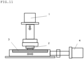
- Figure 11 shows the outline of a reciprocating sliding tester. This is a so-called pin-on-disk reciprocating sliding tester, and enables measuring the abrasion loss.
- reference numeral 1 indicates a pressurizing device
- reference numeral 2 indicates a material to be tested
- reference numeral 3 indicates a mating material.
- Reference numeral 4 is a motor for reciprocally sliding the mating material. The test conditions will be shown below.
- Table 2 shows the abrasion losses of the sliding materials of Example and Comparative Examples. [Table 2] Abrasion loss ( ⁇ m) Example 1 0.7 Comparative Example 1 3.3 Comparative Example 2 12.9 Comparative Example 3 6.9
- the sliding material of Example is usable in severe sliding environmental conditions such as a low-speed and high-load, high-speed and high-rotation, or corrosive environment, for example, in construction machine parts, car engine parts, transmission parts, hydraulic parts, or aircraft parts.
- the sliding material of Example is useful for applications requiring the abrasion resistance and low frictional properties, and enables providing a highly reliable sliding material.
Landscapes
- Engineering & Computer Science (AREA)
- General Engineering & Computer Science (AREA)
- Mechanical Engineering (AREA)
- Chemical & Material Sciences (AREA)
- Materials Engineering (AREA)
- Metallurgy (AREA)
- Organic Chemistry (AREA)
- Sliding-Contact Bearings (AREA)
Abstract
Description
- The present invention relates to a sliding material.
- Sliding materials in which various intermetallic compounds (for example, silicides) are crystallized in a brass alloy matrix to improve the abrasion resistance are known.
-
Patent Literature 1 discloses an abrasion-resistant copper alloy, wherein the weight ratio to Fe and Mn is from 0.3 to 14 and the content is 1 to 15% by weight.Patent Literature 1 states that this ternary compound has higher abrasion resistance than conventional ones containing Mn5Si3 and/or Fe3Si.Patent Literature 1 merely discloses that the addition of Cr has a dispersion effect. -
Patent Literature 2 discloses manganese silicide in brass alloy. InPatent Literature 2, Cr, Zr, or compounds thereof act as a nucleating agent for the silicide deposit, and the addition thereof suppresses the eutectic fine deposition of silicides. That is,Patent Literature 2 discloses that the addition of Cr or Zr in a minute amount enables changing the precipitation morphology of manganese silicide. -
Patent Literature 3 discloses additives such as Ti, Zr, V, and Cr, contributing to the micronization of the structure and the grain boundary strengthening as selective elements in a sintered material comprising a brass alloy containing Cu, Zn, Al, and Si as base metals. Since this sintered material utilizing surface pores is produced unlike ingot material without a step of completely melting the additive components to form alloy, even the sintered material containing the same components exhibits heterogeneous structures unlike the structure of ingot material. -
Patent Literature 4 discloses a material wherein a brass matrix is limited to the β-phase, the amounts of Fe, Mn, and Si added are limited on the assumption that Fe-Mn-Si-based intermetallic compounds having compositions of Mn5Si3 and Fe3Si, and the area rate of the compounds is 3 to 20%. -
Patent Literature 5 discloses a substance, comprising Fe-based silicides such as a Fe-Cr-Si-based intermetallic compound, wherein the brass matrix is limited to the β-phase, but detail of the compound is not clarified. -
- Patent Literature 1:
Japanese Patent Laid-Open No. 60-114545 - Patent Literature 2:
Japanese Patent Laid-Open No. 61-41738 - Patent Literature 3:
Japanese Patent Laid-Open No. 1-252745 - Patent Literature 4:
Japanese Patent Laid-Open No. 2010-159443 - Patent Literature 5:
Japanese Patent Laid-Open No. 2010-265500 - As shown in prior art documents, as the frictional abrasive environment becomes severer, Mn-Si-based intermetallic compounds or improved Mn-Fe-Si-based intermetallic compounds have been increasingly utilized in brass matrices to contribute to improvement in abrasion resistance. Effects such as the precise chemical compositions, the precipitation morphologies, and the hardness of the intermetallic compounds on the friction and abrasion have not, however, been fully inspected.
- The present invention has been completed to solve such a conventional problem, and an object thereof is to provide a sliding material having improved sliding characteristics.
- The present invention is a sliding material, comprising a substrate comprising brass alloy and a Cr-Fe-Si-based intermetallic compound comprised in the substrate, wherein the nanoindentation hardness of regions wherein the Cr-Fe-Si-based intermetallic compound precipitated is 20 GPa or more and 28 GPa or less.
- The present invention enables providing a sliding material having improved sliding characteristics.
-
-
Figure 1 is a sectional schematic diagram of a sliding material of an embodiment. -
Figure 2 is a contour map of the nanoindentation hardness. -
Figure 3 is a sectional view of the nanoindentation hardness. -
Figure 4 is a sectional schematic diagram of a sliding material of Comparative Example. -
Figure 5 is a sectional schematic diagram of a sliding material of Comparative Example. -
Figure 6 is a sectional schematic diagram of a sliding material of Comparative Example. -
Figure 7 is an SEM photograph of a Cr-Fe-Si-based intermetallic compound of the embodiment. -
Figure 8 is an enlarged schematic diagram of the sectional structure of a sliding material of the embodiment. -
Figure 9 is an enlarged schematic diagram of sectional structure of a sliding material of Comparative Example. -
Figure 10 is a figure describing the abrasion of the sliding material of the embodiment. -
Figure 11 is a figure showing a reciprocating sliding tester. - Hereinafter, a sliding material of an embodiment will be described in detail.
-
Figure 1 is a schematic diagram showing a sectional structure of a slidingmaterial 1 of the embodiment.Figure 1 shows a three-dimensional structure of an intermetallic compound viewed from a cross section perpendicular to a sliding surface 1A. Thesliding material 1 comprises a substrate (matrix) 2 and a Cr-Fe-Si-basedintermetallic compound 3. - The
substrate 2 comprises brass alloy. Thesubstrate 2 imparts a shape and mechanical strength depending on its application to the slidingmaterial 1. - The
sliding material 1 of the embodiment contains (Cr,Fe)3Si as a Cr-Fe-Si-basedintermetallic compound 3, containing Cr as the main component. The Cr-Fe-Si-basedintermetallic compound 3 representatively has a structure of (Cr0.85Fe0.15)3Si. - The Cr-Fe-Si-based
intermetallic compound 3 has a composition of Cr Fe, and Si. The Cr-Fe-Si-basedintermetallic compound 3 of the embodiment has a structure of (Cr,Fe)3Si. Each Cr-Fe-Si-basedintermetallic compound 3 has roundish outer shape with curved surfaces. - Numerous Cr-Fe-Si-based
intermetallic compounds 3 contained in thesubstrate 2 are bound to each other to have a spatial structure in which the numerous Cr-Fe-Si-basedintermetallic compounds 3 are connected. The sliding material of the present embodiment has regions with a nanoindentation hardness of 20 GPa or more and 28 GPa or less in which the Cr-Fe-Si-basedintermetallic compound 3 precipitated. The definition and the measurement method of the hardness of the Cr-Fe-Si-basedintermetallic compound 3 will be described below. - The binding ratio between the atoms in the Cr-Fe-Si-based
intermetallic compound 3 was calculated from the composition in % by atom determined by point analysis using SEM-EDS to identify the compound and determine the binding rates of the atoms. For example, in the case of a simple manganese silicide, the binding ratio of Mn to Si of 5:3, the manganese silicide proves to be a compound with a chemical structure of Mn5Si3. - In the notation of this intermetallic compound, components are notated in descending order of content in the same way as in the notation of general alloy components, and for example, an intermetallic compound is notated as a Mn-Si-based intermetallic compound. The Cr-Fe-Si-based
intermetallic compound 3 indicates that a compound comprises Cr as the main component, Fe, and Si. - The present inventors have confirmed that if this compound is ternarized like a Mn-Fe-Si-based intermetallic compound, the main structure remains Mn5Si3, and becomes (Mnx,Fey) (wherein x + y = 1) formed by substituting some manganese atoms, and clarified the substitution ratio thereof. That is, the introduction of the measuring apparatus and an idea for determining the chemical structure enables knowing the precise chemical structure.
- Intermetallic compounds were often evaluated exclusively based on the cross-sectional shape in the past. In the case of friction and abrasion, the three-dimensional precipitation morphology of the compounds however needs to be comprehended in response to the process of abrasion progress.
- The present inventors have developed a corrosion method for dissolving the
brass substrate 2 to leave only the Cr-Fe-Si-basedintermetallic compound 3. The three-dimensional precipitation morphology of the Cr-Fe-Si-basedintermetallic compound 3 can therefore be observed by SEM (secondary electron image). - The spatial structure of the Cr-Fe-Si-based
intermetallic compound 3 can be comprehended by this method. The morphologies of the intermetallic compounds were compared to inspect the effects thereof on friction and abrasion. - The hardness of the Cr-Fe-Si-based
intermetallic compound 3 can be measured with a nanoindenter. - The hardness is measured with a nanoindenter in accordance with "ISO 14577-1 Metallic materials - Instrumented indentation test for hardness and materials parameters-" and the annex thereof, "Annex A (normative) Materials parameters determined from the force/indentation depth data set". An apparatus, HYSITRONTI980, which is available from Bruker Japan, was used for measuring the hardness with a nanoindenter.
- The conditions and the procedure for measuring the nanoindentation hardness will be shown below.
- The conditions for measuring the nanoindentation hardness are as follows.
- Test load: 800 µN
- Loading: 1 s
- Holding: 0.4 s
- Unloading: 1 s
- The ISO notates the measurement conditions as follows.

- The measurement procedure and the method for determining the nanoindentation hardness of the Cr-Fe-Si-based
intermetallic compound 3 are as follows. - 1. A sample surface to be measured is polished into a smooth surface with an ion milling apparatus.
- 2. Components in a visual field including the Cr-Fe-Si-based
intermetallic compound 3 are confirmed with SEM/EDS. It is confirmed that a visual field through a camera of a nanoindentation measuring apparatus is the same as the visual field including the Cr-Fe-Si-basedintermetallic compound 3. The visual field for nanoindentation measurement was determined thereby. - 3. A grid with a grid interval of 1.5 µm is set in the visual field with a size of 13.5 µm × 13.5 µm including the Cr-Fe-Si-based
intermetallic compound 3. The nanoindentation hardness is sequentially measured on 100 grid points in total of the grid under the above-mentioned nanoindentation measurement conditions. - 4. The points of the same nanoindentation hardness are connected by lines based on the above-mentioned measurement results to obtain a contour map.
Figure 2 is the contour map obtained by connecting the points of the same hardness by the lines. The cross section of the contours is then formed by cutting the contours along the line passing through the peak of the nanoindentation hardness ofFigure 2 and parallel to the x-axis (the line D-D' inFigure 2 ).Figure 3 is a cross-sectional view showing the hardness distribution obtained by forming the cross section of the contours. - 5. In the hardness cross-sectional view of
Figure 3 , the regions A show the regions of thesubstrate 2, the regions B show the boundary regions between thesubstrate 2 and the Cr-Fe-Si-basedintermetallic compound 3, and the region C shows the region of the Cr-Fe-Si-basedintermetallic compound 3. - The regions A of the
substrate 2 have a nanoindentation hardness of around 4 GPa. The precipitation of the Cr-Fe-Si-basedintermetallic compound 3 makes the boundary regions B between thesubstrate 2 and the Cr-Fe-Si-basedintermetallic compound 3 harder than thesubstrate 2, and increases the hardness rapidly from the near vicinity of thesubstrate 2. In the region C of the Cr-Fe-Si-basedintermetallic compound 3, the nanoindentation hardness in the central portion is comparatively flat, and is 19.5 GPa or more and 24.4 GPa or less inFigure 2 . - The nanoindentation hardness can be obtained as only discrete values by this measurement method. As a method for expressing the hardness of the Cr-Fe-Si-based
intermetallic compound 3, the regions C in which the hardness was flat and high were therefore considered to be regions in which the Cr-Fe-Si-basedintermetallic compound 3 precipitated. The nanoindentation hardness of the regions C was defined as the hardness of the Cr-Fe-Si-basedintermetallic compound 3. - In the determination of the regions B, the boundary regions B are defined as portions satisfying the following condition:

- The regions C, which are harder than the thus determined regions B, are considered to be regions in which the Cr-Fe-Si-based
intermetallic compound 3 precipitated. In the case of the Cr-Fe-Si-basedintermetallic compound 3, shown inFigure 2 , the region C has a nanoindentation hardness of 19.5 GPa or more and 24.4 GPa or less. - In the nanoindentation hardness measurement, multiple visual fields (for example, five visual fields) may be reflected. In the case, the range from the minimum value to the maximum value determined from the nanoindentation hardness of the
visual fields 1 to 5 is defined as the nanoindentation hardness of the Cr-Fe-Si-basedintermetallic compound 3. The procedure for measuring the nanoindentation hardness of other intermetallic compounds and the determination method are also performed in the same process. - The three-dimensional binding structure and the nanoindentation hardness of particles of the Cr-Fe-Si-based
intermetallic compound 3 improve the slidability of the slidingmaterial 1 of the embodiment. - The effect of the sliding
material 1 of the embodiment was confirmed in comparison between the compositions, the structures, the spatial structures, or the nanoindentation hardness of the slidingmaterial 1 of the embodiment and the sliding materials of Comparative Examples. -
Figure 4 is a schematic diagram cross-sectional view of the three-dimensional shape of the sliding material of Comparative Example, containing a Mn-Si-based intermetallic compound. As shown inFigure 4 , the Mn-Si-based intermetallic compound has a chemical structure of Mn5Si3, preferential crystal growth directions, is separated into pieces, and has a shape to grow into hexagonal acicular crystals. - The Mn-Si-based intermetallic compound had a nanoindentation hardness of 16.8 GPa. Since stress is concentrated at the corners, this hexagonal acicular Mn-based silicide compound is lacking in toughness.
- The Mn-Si-based intermetallic compound is highly crystalline to be easily broken, and is partially fractured on the frictional/abrasive surface, separated, and broken away to be foreign objects, which leads to a problem that the foreign objects roll on the sliding surface to damage the mating material at this time, and also results in seizure consequently. Especially in a sliding material to be used under severe conditions, the Mn-Si-based intermetallic compound is problematic.
-
Figure 5 is a schematic diagram cross-sectional view of the three-dimensional shape of a sliding material containing the Mn-Fe-Si-based intermetallic compound. As shown inFigure 5 , the Mn-Fe-Si-based intermetallic compound has a chemical structure of (Mn,Fe)5Si3. The Mn-Fe-Si-based intermetallic compound has preferential crystal growth directions, is separated into pieces, and has a shape to grow into hexagonal acicular crystals like Mn-Si-based intermetallic compound. - The Mn-Fe-Si-based intermetallic compound has proved to be partially eutectic crystal into granular continuous structure. The Mn-Fe-Si-based intermetallic compound has a nanoindentation hardness of 18.5 GPa. The ternarization of the Mn-Fe-Si-based intermetallic compound increases the nanoindentation hardness slightly.
- The sliding
material 1 of the embodiment has a structure of (Cr,Fe)3Si in thesubstrate 2 of the cast brass-based alloy, a spatial structure that is roundish and composed of curved surfaces and in which the Cr-Fe-Si-basedintermetallic compounds 3 are partially connected, and the regions C of the Cr-Fe-Si-basedintermetallic compound 3 has a nanoindentation hardness of 20 GPa or more and 28 GPa or less. Since the slidingmaterial 1 of the embodiment comprises the Cr-Fe-Si-basedintermetallic compound 3, the slidingmaterial 1 has high abrasion resistance and low frictional properties. - Intermetallic compounds comprising Cr, Fe, and Si include two compounds, namely (Cr,Fe)3Si (specifically (Cr0.85Fe0.15)3Si), which is the Cr-Fe-Si-based
intermetallic compound 3 of the embodiment, containing Cr as the main component, and the Fe-Cr-Si-based intermetallic compound (Fe,Cr)3Si (specifically (Fe0.85Cr0.15)3Si), containing Fe as the main component. These two intermetallic compounds exhibit completely different morphologies. -
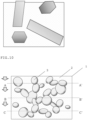
Figure 6 shows the morphology of the Fe-Cr-Si-based intermetallic compound. The Fe-Cr-Si-based intermetallic compound has a structure of (Fe0.35Cr0.15)3Si. The Fe-Cr-Si-based intermetallic compound is a compound in which Cr3Si compound are partially (85%) substituted with Fe atoms, which are transition metal atoms in the same way as Cr atoms. -
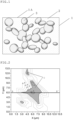
Figure 7 is a SEM photograph showing the three-dimensional structure of the Cr-Fe-Si-basedintermetallic compound 3. As shown inFigure 7 , the Cr-Fe-Si-basedintermetallic compound 3 has a morphology that is roundish and composed of curved surfaces and three-dimensionally connected. - This three-dimensionally connected morphology is a morphology that Comparative Example, shown in
Figure 4 , does not have, and leads to excellent characteristics in tribological performance. Meanwhile, the Fe-Cr-Si-based intermetallic compounds precipitated in a massive and finely dispersed state, and therefore less contribute to tribological characteristics. - The Cr-Fe-Si-based
intermetallic compound 3 and the Fe-Cr-Si-based intermetallic compound tend to precipitate simultaneously. The present inventors have attempted the separative solidification of these two silicides for utilizing only the Cr-Fe-Si-based intermetallic compound. The control of solidification conditions enabled successfully solidifying the Cr-Fe-Si-basedintermetallic compound 3 separately from the Fe-Cr-Si-based intermetallic compound. This enabled comprehending high frictional/abrasive characteristics specialized in the Cr-Fe-Si-based intermetallic compound to achieve the embodiment. - Although the Cr-Fe-Si-based
intermetallic compound 3 and the Fe-Cr-Si-based intermetallic compound contain Cr, Fe, and Si as components in the same way, the compounds are completely different in morphology and hardness, so that the frictional/abrasive performances caused by the hard compounds are different. The embodiment is for utilizing, among these compounds, the Cr-Fe-Si-basedintermetallic compound 3 containing Cr as the main component and having a spatial structure that is roundish and composed of curved surfaces and partially connected. - The cast brass-based alloy is evaluated for abrasion resistance and low frictional properties (low frictional coefficient properties) in accordance with the basic tribological expression (1).

- The frictional coefficient µ is directly proportional to the shearing force of the lubricating substance and inversely proportional to the hardness of the base metal. The hardness PH is a value obtained by dividing the load by the contact area. To reduce the frictional coefficient µ, it is necessary to increase the hardness of the intermetallic compound serving as load points during the friction or to reduce the contact area of the intermetallic compound.
- That is ideally, if the shape of the compound is made more similar to sphere to reduce the contact area, and the compound is hard, the frictional coefficient can be reduced.
-
Figure 8 shows the Cr-Fe-Si-basedintermetallic compound 3 of the embodiment. As shown inFigure 8 , the Cr-Fe-Si-basedintermetallic compound 3 of the embodiment is hard and has a compound morphology that is roundish and composed of curved surfaces and connected. - The Cr-Fe-Si-based
intermetallic compound 3 of the embodiment is hard and has a shape of reduced frictional surface and increased radiating area therefore it can be considered that the compound enables reducing the frictional coefficient. -
Figure 9 shows the Mn-Fe-Si-based intermetallic compound of Comparative Example. As shown inFigure 9 , the Mn-Fe-Si-based intermetallic compounds of Comparative Example have polygonal shape, and are independent and unconnected. - In accordance with the above-mentioned basic tribological expression (1), the effect of the Cr-Fe-Si-based
intermetallic compound 3 of the embodiment means that an increases in PH (hardness) reduces the frictional coefficient, the intervention of the lubricant reduces the frictional work, represented by |µ × load × velocity, and this enables reducing the generation of frictional heat, so that a low frictional effect is exhibited. - The abrasion loss (V) of a sliding material is represented by the expression (2).

- The abrasion loss (V) is directly proportional to the abrasion coefficient Z, the load P, and the frictional distance L and inversely proportional to the hardness PH. Accordingly, an increase in the hardness of a compound to precipitate in brass alloy, which is soft, enables reducing the abrasion loss.
- The regions C of the Cr-Fe-Si-based
intermetallic compound 3 of the embodiment have a nanoindentation hardness of 20 GPa to 28 GPa, and are in a structure having high abrasion resistance. - The intermetallic compound serves as load points during the friction to generate intense frictional heat. This frictional heat is dissipated through the interface between the intermetallic compound and the copper alloy matrix. Accordingly, the three-dimensional connection of the compound enables increasing the surface area of the whole intermetallic compound, and enhancing the heat dissipation efficiency rapidly. Such satisfactory heat dissipation efficiency during the friction enables preventing a rise in surface temperature and relieving severe frictional conditions.
- For example, when the acicular Mn5Si3 compounds of Comparative Example, which precipitated alone, serve as load points to increase frictional heat, this may heat the intermetallic compound to high temperature, softens the compound/matrix interface, and makes the compound interface unstable to separate.
- Since the Cr-Fe-Si-based
intermetallic compounds 3 of the embodiment have large surface areas, and are connected, the heat exchanging area is meanwhile increased, which enables suitably diffusing frictional heat generated by the concentrated load. Thus, having the three-dimensional structure is an important factor in the case of friction and abrasion. - Having the structure that is three-dimensionally connected is particularly advantageous in abrasion resistance form the viewpoint of tribological performance. As shown in
Figure 10 , even though the abrasion progresses from A-A' through B-B' to C-C', the Cr-Fe-Si-basedintermetallic compound 3 always appears, so that the abrasion resistance and the low frictional properties are continuously maintained. - The shape and the continuity of the Cr-Fe-Si-based
intermetallic compound 3 have an important meaning, the Cr-Fe-Si-basedintermetallic compound 3 effectively functions as high-temperature and high-load bearing materials with respect to the application thereof. The continuity of the Cr-Fe-Si-basedintermetallic compound 3 has an excellent structure for promoting the formation of optimal low frictional surfaces while the abrasion progresses. - Hereinafter, Examples of the present invention will be described. The present invention is not limited to the following Example.
- Table 1 shows the compositions of intermetallic compounds contained in the sliding materials of Example and Comparative Examples. The sliding materials of Example and Comparative Examples contain the intermetallic compounds shown in Table 1 in a cast brass-based alloy matrix, which is Cu-26Zn-5Al.
- Example 1 is a sliding material in which the Cr-Fe-Si-based
intermetallic compound 3 precipitated in the substrate. Comparative Example 1 is a sliding material in which a Fe-Cr-Si-based intermetallic compound precipitated in the substrate. Comparative Example 2 is a sliding material in which Mn5Si3, a so-called Mn-Si-based intermetallic compound, precipitated in the substrate. Comparative Example 3 is a sliding material in which (Mn,Fe)5Si3, a so-called Mn-Fe-Si-based intermetallic compound, precipitated in the substrate. - Table 1 shows the chemical formulae of the intermetallic compounds, the precipitation morphologies of the intermetallic compounds (shapes and continuity (bonding or connection) of the intermetallic compounds), and the nanoindentation hardness (GPa) of regions in which the intermetallic compounds are present. The amount of Si added was 0.3%, and the amounts of Mn, Fe, Cr, and others added were determined depending on the compositions of the compounds to precipitate.
[Table 1] Chemical formula Shape Continuity Hardness (GPa) Example 1 (Cr,Fe)3Si Roundish and composed of curved surfaces Continuous 19.5 ~ 27.9 Comparative Example 1 (Fe,Cr)3Si Fine polygonal shape Discontinuous 9.5 ~ 14.3 Comparative Example 2 Mn5Si3 Hexagonal acicular shape Discontinuous 11.4 ~ 16.8 Comparative Example 3 (Mn,Fe)5Si3 Hexagonal acicular shape and granular shape Partially continuous 12.2 ~ 18.5 - Pure Cu base metal was first molten at a melting temperature of 1100°C. Zn was then added thereto in a predetermined amount to produce Cu-Zn alloy. Al was next added thereto and molten, and the temperature was raised to 1200°C. Mother alloys of elements required were added thereto and molten. All the alloys were molten and cast so as to contain the predetermined components and processed into a specimen shape.
- In the case of the Cr-Fe-Si-based
intermetallic compound 3 of Example 1, regions having a nanoindentation hardness of 19.5 GPa or more and 27.9 GPa or less in the regions C of the Cr-Fe-Si-basedintermetallic compound 3 were observed. In the case of the Fe-Cr-Si-based intermetallic compound of Comparative Example 1, regions having a nanoindentation hardness of 9.5 GPa or more and 14.3 GPa or less were observed. In the case of the Mn-Si-based intermetallic compound of Comparative Example 2, regions having a nanoindentation hardness of 11.4 GPa or more and 16.8 GPa or less were observed. In the case of the Mn-Fe-Si-based intermetallic compound of Comparative Example 3, regions having a nanoindentation hardness of 12.2 GPa or more and 18.5 GPa or less were observed. - Thus, the Cr-Fe-Si-based
intermetallic compound 3 of Example 1 is so hard that the hardness thereof influences the tribological performance greatly. -
Figure 11 shows the outline of a reciprocating sliding tester. This is a so-called pin-on-disk reciprocating sliding tester, and enables measuring the abrasion loss. In the figure,reference numeral 1 indicates a pressurizing device,reference numeral 2 indicates a material to be tested, andreference numeral 3 indicates a mating material.Reference numeral 4 is a motor for reciprocally sliding the mating material. The test conditions will be shown below. - Tester: Reciprocating dynamic load tester
- Sliding velocity: 2 m/min
- Reciprocating sliding distance: 150 mm
- Total sliding distance: 500 m
- Test temperature (bearing back surface temperature): 100°C
- Mating material: S45C surface-hardened material with a surface roughness, Ra 3.0
- Lubricating oil: VG32
- Frictional test load: Constant load of 30 MPa
- Table 2 shows the abrasion losses of the sliding materials of Example and Comparative Examples.
[Table 2] Abrasion loss (µm) Example 1 0.7 Comparative Example 1 3.3 Comparative Example 2 12.9 Comparative Example 3 6.9 - It can be seen that much higher abrasion resistance can be achieved in the sliding material of Example 1 than the sliding material of Comparative Example 1 or the sliding materials of Comparative Examples 2 and 3 that have been conventionally used.
- Thus, it was proved that the excellent improvement in tribological performance can be achieved in the sliding material of Example by the precipitation of the Cr-Fe-Si-based
intermetallic compound 3 that has high tribological performance in terms of the precipitation morphology and the nanoindenter hardness. - The sliding material of Example is usable in severe sliding environmental conditions such as a low-speed and high-load, high-speed and high-rotation, or corrosive environment, for example, in construction machine parts, car engine parts, transmission parts, hydraulic parts, or aircraft parts. The sliding material of Example is useful for applications requiring the abrasion resistance and low frictional properties, and enables providing a highly reliable sliding material.
- Note that the structure, and the materials or the ratio therebetween of the composition of the sliding material of the embodiment are merely illustrations, and the present invention is not limited to these.
Claims (4)
- A sliding material, comprising:a substrate comprising brass alloy anda Cr-Fe-Si-based intermetallic compound comprised in the substrate,wherein nanoindentation hardness of regions wherein the Cr-Fe-Si-based intermetallic compound precipitated is 20 GPa or more and 28 GPa or less.
- The sliding material according to claim 1, wherein the Cr-Fe-Si-based intermetallic compound has a spatial structure in which the Cr-Fe-Si-based intermetallic compounds are connected.
- The sliding material according to claim 1 or 2, wherein the Cr-Fe-Si-based intermetallic compound has a shape that is roundish and composed of curved surfaces.
- The sliding material according to any one of claims 1 to 3, wherein the Cr-Fe-Si-based intermetallic compound has a chemical structure of (Cr,Fe)3Si.
Applications Claiming Priority (2)
| Application Number | Priority Date | Filing Date | Title |
|---|---|---|---|
| JP2022059915A JP7105522B1 (en) | 2022-03-31 | 2022-03-31 | Sliding material |
| PCT/JP2023/013186 WO2023190873A1 (en) | 2022-03-31 | 2023-03-30 | Sliding material |
Publications (2)
| Publication Number | Publication Date |
|---|---|
| EP4502204A1 true EP4502204A1 (en) | 2025-02-05 |
| EP4502204A4 EP4502204A4 (en) | 2026-04-22 |
Family
ID=82556734
Family Applications (1)
| Application Number | Title | Priority Date | Filing Date |
|---|---|---|---|
| EP23780881.1A Pending EP4502204A4 (en) | 2022-03-31 | 2023-03-30 | SLIDING MATERIAL |
Country Status (6)
| Country | Link |
|---|---|
| US (1) | US20250172175A1 (en) |
| EP (1) | EP4502204A4 (en) |
| JP (1) | JP7105522B1 (en) |
| KR (1) | KR20240167845A (en) |
| CN (1) | CN118900923A (en) |
| WO (1) | WO2023190873A1 (en) |
Families Citing this family (1)
| Publication number | Priority date | Publication date | Assignee | Title |
|---|---|---|---|---|
| JP7539192B2 (en) * | 2022-07-05 | 2024-08-23 | 三協オイルレス工業株式会社 | Cam device |
Family Cites Families (6)
| Publication number | Priority date | Publication date | Assignee | Title |
|---|---|---|---|---|
| JPS60114545A (en) * | 1983-11-25 | 1985-06-21 | Kobe Steel Ltd | Wear resistant copper alloy |
| DE3427740A1 (en) * | 1984-07-27 | 1986-02-06 | Diehl GmbH & Co, 8500 Nürnberg | BRASS ALLOY, MANUFACTURING METHOD AND USE |
| JP2605791B2 (en) * | 1988-03-31 | 1997-04-30 | 三菱マテリアル株式会社 | Transmission synchronous ring made of Cu-based sintered alloy |
| JP5342882B2 (en) * | 2009-01-06 | 2013-11-13 | オイレス工業株式会社 | High strength brass alloy for sliding member and sliding member |
| JP5616032B2 (en) * | 2009-05-13 | 2014-10-29 | オイレス工業株式会社 | High strength brass casting for sliding member and sliding member |
| WO2011145220A1 (en) * | 2010-05-21 | 2011-11-24 | オイレス工業株式会社 | High-strength brass alloy for sliding member, and sliding member |
-
2022
- 2022-03-31 JP JP2022059915A patent/JP7105522B1/en active Active
-
2023
- 2023-03-30 US US18/842,545 patent/US20250172175A1/en active Pending
- 2023-03-30 EP EP23780881.1A patent/EP4502204A4/en active Pending
- 2023-03-30 CN CN202380028231.0A patent/CN118900923A/en active Pending
- 2023-03-30 KR KR1020247034867A patent/KR20240167845A/en active Pending
- 2023-03-30 WO PCT/JP2023/013186 patent/WO2023190873A1/en not_active Ceased
Also Published As
| Publication number | Publication date |
|---|---|
| US20250172175A1 (en) | 2025-05-29 |
| JP2023150691A (en) | 2023-10-16 |
| KR20240167845A (en) | 2024-11-28 |
| CN118900923A (en) | 2024-11-05 |
| JP7105522B1 (en) | 2022-07-25 |
| EP4502204A4 (en) | 2026-04-22 |
| WO2023190873A1 (en) | 2023-10-05 |
Similar Documents
| Publication | Publication Date | Title |
|---|---|---|
| Madhukar et al. | Fabrication and characterization two step stir casting with ultrasonic assisted novel AA7150-hBN nanocomposites | |
| Priarone et al. | Tool wear and surface quality in milling of a gamma-TiAl intermetallic | |
| US8993493B2 (en) | Sliding part made of Pb-free Cu-Bi based sintered alloy | |
| EP1964937A1 (en) | Cu-Ni-Si-based copper alloy sheet material and method of manufacturing same | |
| Jain et al. | Effect of first and second passes on microstructure and wear properties of titanium dioxide-reinforced aluminum surface composite via friction stir processing | |
| Janbozorgi et al. | Improving tribological behavior of friction stir processed A413/SiCp surface composite using MoS2 lubricant particles | |
| EP4502204A1 (en) | Sliding material | |
| EP0141501A1 (en) | Extruded aluminum alloys having improved wear resistance and process for preparing same | |
| US4957822A (en) | Laminated material for friction bearing elements, comprising an antifriction layer of an aluminum based bearing material | |
| US6866085B2 (en) | Plastically worked cast aluminum alloy product, a manufacturing method thereof and a coupling method using plastic deformation thereof | |
| Zedan et al. | Effects of free-cutting elements addition on the microstructure, hardness, and machinability of Al-11% Si–Cu–Mg casting alloys | |
| EP3845677A1 (en) | Aluminum alloy material, and braided shield wire, electroconductive member, member for cell, fastening component, component for spring, component for structure, and cabtire cable using same | |
| Liu et al. | Fabrication and evaluation of Ti6Al4V/NiCrBSi bimetallic structure with Nb/Cu bilayer by laser melting deposition | |
| Edlabadkar et al. | Optimization of machining parameters and performance analysis of AA2024/ZrO₂ metal matrix composite using TOPSIS: insights into squeeze casting and tribological behavior | |
| Hamed et al. | Milling parameters of Al-Cu and Al-Si cast alloys | |
| Rawal et al. | Fabrication, characterization and micro-machinability of stir-cast Al6061/GNPs+ Mg nanocomposite | |
| Fatoba et al. | The effects of Sn addition on the microstructure and surface properties of laser deposited Al-Si-Sn coatings on ASTM A29 steel | |
| JP3351181B2 (en) | Wear-resistant aluminum alloy sliding member | |
| EP1967596A1 (en) | Cu-Ni-Si-based copper alloy sheet material and method of manufacturing same | |
| JP4422255B2 (en) | Aluminum base bearing alloy | |
| Viswanatha et al. | Effect of applied load on tribological study of hybrid metal matrix composites | |
| Li et al. | Microstructures and mechanical properties of hot-rolled and annealed Al-27% Si alloy strips | |
| Ponhan et al. | Effect of SiC content on mechanical and tribological performance of ADC14-P-SiC nanocomposites synthesized via ultrasonically assisted stir casting approach | |
| Beranoagirre et al. | Turning of gamma TiAl intermetallic alloys | |
| Kikuchi et al. | Machinability of experimental Ti-Cu alloys |
Legal Events
| Date | Code | Title | Description |
|---|---|---|---|
| STAA | Information on the status of an ep patent application or granted ep patent |
Free format text: STATUS: THE INTERNATIONAL PUBLICATION HAS BEEN MADE |
|
| PUAI | Public reference made under article 153(3) epc to a published international application that has entered the european phase |
Free format text: ORIGINAL CODE: 0009012 |
|
| STAA | Information on the status of an ep patent application or granted ep patent |
Free format text: STATUS: REQUEST FOR EXAMINATION WAS MADE |
|
| 17P | Request for examination filed |
Effective date: 20240906 |
|
| AK | Designated contracting states |
Kind code of ref document: A1 Designated state(s): AL AT BE BG CH CY CZ DE DK EE ES FI FR GB GR HR HU IE IS IT LI LT LU LV MC ME MK MT NL NO PL PT RO RS SE SI SK SM TR |
|
| DAV | Request for validation of the european patent (deleted) | ||
| DAX | Request for extension of the european patent (deleted) | ||
| A4 | Supplementary search report drawn up and despatched |
Effective date: 20260325 |
|
| RIC1 | Information provided on ipc code assigned before grant |
Ipc: C22C 9/04 20060101AFI20260319BHEP Ipc: F16C 33/12 20060101ALI20260319BHEP |