EP4501841A2 - Notbremsvorrichtung für eine seilwinde mit einer um eine drehachse drehbaren seiltrommel, seilwinde und verfahren zum betreiben einer notbremsvorrichtung - Google Patents
Notbremsvorrichtung für eine seilwinde mit einer um eine drehachse drehbaren seiltrommel, seilwinde und verfahren zum betreiben einer notbremsvorrichtung Download PDFInfo
- Publication number
- EP4501841A2 EP4501841A2 EP24217478.7A EP24217478A EP4501841A2 EP 4501841 A2 EP4501841 A2 EP 4501841A2 EP 24217478 A EP24217478 A EP 24217478A EP 4501841 A2 EP4501841 A2 EP 4501841A2
- Authority
- EP
- European Patent Office
- Prior art keywords
- driver
- cable drum
- braking device
- emergency braking
- brake
- Prior art date
- Legal status (The legal status is an assumption and is not a legal conclusion. Google has not performed a legal analysis and makes no representation as to the accuracy of the status listed.)
- Granted
Links
Images



Classifications
-
- B—PERFORMING OPERATIONS; TRANSPORTING
- B66—HOISTING; LIFTING; HAULING
- B66D—CAPSTANS; WINCHES; TACKLES, e.g. PULLEY BLOCKS; HOISTS
- B66D5/00—Braking or detent devices characterised by application to lifting or hoisting gear, e.g. for controlling the lowering of loads
- B66D5/02—Crane, lift hoist, or winch brakes operating on drums, barrels, or ropes
- B66D5/12—Crane, lift hoist, or winch brakes operating on drums, barrels, or ropes with axial effect
-
- B—PERFORMING OPERATIONS; TRANSPORTING
- B66—HOISTING; LIFTING; HAULING
- B66D—CAPSTANS; WINCHES; TACKLES, e.g. PULLEY BLOCKS; HOISTS
- B66D5/00—Braking or detent devices characterised by application to lifting or hoisting gear, e.g. for controlling the lowering of loads
- B66D5/02—Crane, lift hoist, or winch brakes operating on drums, barrels, or ropes
- B66D5/18—Crane, lift hoist, or winch brakes operating on drums, barrels, or ropes for generating braking forces which are proportional to the loads suspended; Load-actuated brakes
- B66D5/22—Crane, lift hoist, or winch brakes operating on drums, barrels, or ropes for generating braking forces which are proportional to the loads suspended; Load-actuated brakes with axial effect
-
- B—PERFORMING OPERATIONS; TRANSPORTING
- B66—HOISTING; LIFTING; HAULING
- B66D—CAPSTANS; WINCHES; TACKLES, e.g. PULLEY BLOCKS; HOISTS
- B66D5/00—Braking or detent devices characterised by application to lifting or hoisting gear, e.g. for controlling the lowering of loads
- B66D5/02—Crane, lift hoist, or winch brakes operating on drums, barrels, or ropes
- B66D5/18—Crane, lift hoist, or winch brakes operating on drums, barrels, or ropes for generating braking forces which are proportional to the loads suspended; Load-actuated brakes
Definitions
- the invention is based on an emergency braking device for a cable winch with a cable drum rotatable about a rotation axis, a cable winch and a method for operating an emergency braking device according to the preamble of the independent claims.
- Cable winches are used in the rescue sector, for example in conjunction with helicopters as rescue winches, which usually meet a "Loss of HEC" requirement of the WASA.
- the US 5904229 A1 concerns a braking arrangement which is used as an automatically activated emergency brake for lifting platforms and elevators, among others.
- the approach presented here presents an improved emergency braking device for a cable winch with a cable drum that can rotate about a rotation axis, an improved cable winch and an improved method for operating an emergency braking device according to the main claims.
- the measures listed in the dependent claims enable advantageous further developments and improvements of the device specified in the independent claim.
- the approach presented here describes an emergency braking device that can be designed to slow down a falling load, such as a person hanging from a rope, to a standstill without additional energy being supplied. Sudden braking can also be avoided. This means that, for example, a maximum force acting on the rope can be reduced until it comes to a standstill. This means, for example, that a suddenly rapidly increasing force acting on the rope can be reduced.
- An emergency braking device for a cable winch with a cable drum that can rotate about a rotation axis wherein the emergency braking device has a braking unit that is designed to brake the cable drum when a translational force acts on the braking unit.
- the emergency braking device also has a driver that can rotate about the rotation axis and is linearly movable along the rotation axis and is designed to engage in a driver contour of the cable drum in an active state of the emergency braking device in order to transmit a rotational movement of the cable drum to the driver.
- a feeder with a thread and a connecting structure wherein the feeder and the driver are connected via the connecting structure in a rotationally fixed manner and are linearly movable along the axis of rotation.
- the thread engages in a counter thread in order to cause a linear movement of the feeder in the direction of the braking unit through the rotational movement transmitted from the driver to the feeder in order to exert the translational force on the braking unit.
- the emergency braking device can be referred to, for example, as a one-time brake that is activated in emergencies, for example in the event of uncontrolled abseiling, and can therefore be safety-relevant.
- the emergency braking device can be arranged, for example, on a helicopter with a cable winch, for example a rescue helicopter.
- the cable winch can be designed to unwind a cable so that, for example, people and additionally or alternatively objects can be lifted or lowered.
- the cable can be wound around the cable drum.
- the emergency braking device is inactive, the driver can be decoupled from the cable drum so that movement of the cable drum is not hindered by the emergency braking device.
- the driver when the driver is inactive, it can be held away from the cable drum using a restraint device. When active, the driver can be pressed against the driver using a spring.
- the delivery device can, for example, be screwed in the direction of the cable drum using the thread and the counter thread, thereby exerting the translational force on the braking unit.
- the counter thread can be fixed.
- the counter thread can be fixedly arranged on a housing of the cable winch or a structure. The counter thread can thus be decoupled from a rotation of the cable drum, so that the cable drum can rotate relative to the counter thread.
- the braking unit can brake the cable drum using the translational force, which can thus act as a braking force.
- a magnitude of the translational force can advantageously be related to a torque acting on the cable drum, which is caused, for example, by a falling load.
- the translational force can thus depend on a rotational speed of the cable drum, so that the translational force can be sufficient in any case to brake the cable drum.
- the driver can advantageously engage positively in the driver contour, so that these two components can be firmly connected to one another.
- the emergency braking device can be used for various applications where rotating objects have to be brought to a stop (emergency stop).
- the said cable drum represents a rotating part that can be stopped by the emergency braking device.
- the delivery device can have a retaining collar with the connecting structure and a receiving section for receiving a spring unit, wherein the spring unit can be secured in an inactive state of the emergency braking device.
- the spring unit can be released in the active state of the emergency braking device in order to be able to press the driver along the axis of rotation into the driver contour.
- the connecting structure can therefore be implemented in the retaining collar, for example as a through-opening or as a recess.
- the receiving section can be designed as a niche-like recess so that the spring unit fits into it.
- the released spring unit can advantageously cause the linear movement of the driver in order to connect the driver to the cable drum in a rotationally fixed manner.
- the driver can be held back in the inactive state of the emergency braking device using a cable, for example a steel cable.
- the cable can counteract a pre-tensioned wave spring, which can press the driver against the cable drum if the cable is severed.
- the emergency braking device can have a trigger that can be designed to release the spring unit.
- the trigger can be activated manually by a user, for example, or automatically, for example when a rotational speed of the cable drum is exceeded.
- the trigger can comprise pyrotechnics that destroy a retaining device for holding back the driver.
- a cable for holding back the driver can be severed using the trigger.
- the emergency braking device can advantageously be referred to as a safety component that can be designed to protect people.
- the braking unit may comprise a brake disc and a brake pad, wherein the brake disc may be shaped to be pressed against the brake pad using the translational force to brake the cable drum.
- the translational force may advantageously be dependent on the rotational speed and additionally or alternatively on the falling load, i.e. the person hanging on the cable, so that the cable drum can be braked.
- the delivery device can be shaped in such a way that the brake disc can be pressed against the brake pad. This means that the brake disc can be pressed onto the brake pad and the resulting frictional force can slow down and ultimately stop the rotation of the cable drum.
- the brake pad can be rigidly connected to the cable drum.
- the brake pad can be formed as an annular extension of the cable drum.
- the brake unit can have a brake package that includes the brake disc, a holder and a further spring unit arranged between the brake disc and the holder.
- Using the further spring unit can prevent the cable drum from stopping suddenly.
- the braking process can be perceived as more pleasant for a person hanging on the cable, since the braking effect is mitigated by the spring unit.
- the driver can have at least one projection that can be designed to engage in the driver contour.
- the projection can be referred to as a holding element, for example, and can be shaped as a tooth, for example, that can engage in the driver contour.
- the driver contour can form at least one ramp. This can advantageously prevent the driver from engaging in the driver contour when the cable drum moves in a direction of rotation for rolling up the cable.
- the cable winch can advantageously be designed for rescue helicopters, such as those used in the mountains or on water.
- the cable drum can advantageously be designed to wind up a rescue cable and to additionally or alternatively unwind it.
- the cable drum can be arranged so that it can move around the axis of rotation.
- the method comprises a step of engaging the driver in the driver contour of the cable drum in order to transmit the rotary movement of the cable drum to the driver, a step of transmitting the rotary movement of the driver on the deliverer and a step of causing the linear movement of the deliverer in the direction of the braking unit by the engagement of the thread in the counter thread and by the rotational movement transmitted from the driver to the deliverer and a step of exerting a translational force on the braking unit by the linear movement of the deliverer in order to brake the cable drum using the braking unit.
- the method advantageously makes it possible to secure the cable winch for emergencies, so that the cable drum can be braked and brought to a standstill using the emergency braking device in the event of, for example, an uncontrolled descent.
- the method can comprise a step of unlocking the emergency braking device using a trigger in order to be able to cause the driver to engage in the driver contour.
- the emergency braking device can be activated by the unlocking step.
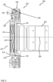
- Fig. 1 shows a schematic sectional view of a cable winch 100 with an emergency braking device 102 according to an embodiment.
- the cable winch 100 is arranged, for example, in or on a helicopter, for example a rescue helicopter.
- the cable winch 100 is shown in a longitudinal section and has the emergency braking device 102 and a rotating part, for example in the form of a cable drum 104.
- the cable drum 104 is designed, for example, to wind up or unwind a cable and is therefore rotatable about an axis of rotation 106.
- the emergency braking device 102 can also be used to brake other rotating parts, for example a rotating machine part of a work machine.
- the cable drum 104 can be understood, for example, as a section of a shaft.
- the emergency braking device 102 is also referred to as an arrestor, for example, and has a braking unit 108, a driver 110 and a feeder 112.
- the braking unit 108 is designed to brake the cable drum 104 when a translational force acts on the braking unit 108.
- the braking unit 108 or at least parts thereof are arranged or can be arranged on a housing, for example.
- the driver 110 is rotatable about the rotation axis 106 and is arranged to be linearly movable along the rotation axis 106.
- the driver 110 is shaped to engage in a driver contour of the cable drum 104 in an active state of the emergency braking device 102, also referred to as the braking state, in order to transmit a rotational movement of the cable drum 104 to the driver 110.
- the driver 110 is also connected to the feeder 112 in a rotationally fixed manner and linearly along the axis of rotation 106, i.e. movably in the direction of the cable drum 104.
- the feeder 112 has a thread 114 and a connecting structure 116 for this purpose.
- the feeder 112 is coupled to the driver 110 via the connecting structure 116, which is shaped, for example, as a through-opening.
- the thread 114 engages in a fixed counter-thread 118 that is decoupled from a rotation of the cable drum 104.
- a torque transmitted from the cable drum 104 to the thread 114 via the driver 110 thus leads to a rotation of the thread 114 in the counter thread 118.
- the emergency braking device 102 screws in using the thread 114 and the counter thread 118 when a load, for example a person hanging from a rope, falls.
- the emergency braking device 102 or more precisely the brake unit 108, intercepts the load, which acts as a translational force on the brake unit 108, and stops the rotational movement.
- energy from a rotating part is absorbed via the thread 114 and the counter thread 118 and used to slow down the rotating part. If the thread 114 and the counter thread 118 are designed to be stiff, energy from the rotating part can be converted into heat energy via the thread 114 and the counter thread 118 and the rotating part can thus be slowed down somewhat.
- the deliverer 110 has an annular retaining collar 120 on which the connecting structure 116 is arranged or in which it is integrated.
- the deliverer 112 has a receiving section 122 which is designed to receive a spring unit 124.
- the spring unit 124 is further secured in an inactive state of the emergency braking device 100 and is released in the active state of the emergency braking device 100 in order to press the driver 110 along the axis of rotation 106 into the driver contour.
- the emergency braking device 100 Only optionally does the emergency braking device 100 have a trigger which is designed to release the spring unit 124. The trigger is actuated manually by a user, for example, or mechanically, for example when the rotational speed of the cable drum 104 is exceeded.
- the trigger comprises a pyrotechnic that is used to release the pre-tensioned driver 110. After the driver 110 is released, an unintentional unrolling of the cable from the cable drum 104 can be reliably prevented by using the emergency braking device 102.
- the brake unit 108 has a brake disk 126 and a brake pad 128.
- the brake disk 126 is shaped to act on the brake pad 128 using the translational force. In other words, the brake disk 126 is pressed onto the brake pad 128 and the resulting frictional force leads to the braking of the rotary movement of the cable drum 104.
- the deliverer 112 is therefore shaped to press the brake disk 126 onto the brake pad 128. This is done, for example, by means of a connection point between the deliverer 112 and the brake unit 108 in the area of the retaining collar 120.
- the brake unit 108 is designed in a ring-like manner according to this embodiment.
- the brake disk 126 is decoupled from the rotation of the cable drum 104, i.e. it does not rotate with the cable drum 104.
- the brake pad 128, on the other hand, is rigidly coupled to the cable drum 104 and rotates accordingly with the cable drum 104.
- the brake disk 126 is coupled to a further spring unit 130, which is designed in such a way that it at least partially counteracts the translational force in order to avoid a sudden stop of the cable drum 104. Instead, using the further spring unit 130, a comparatively gentle braking is effected, so that, for example, the cable and the person are protected during the braking process. In other words, the spring force counteracts the translational force.
- the emergency braking device 102 is designed as an arrestor, i.e. as an emergency brake, without an energy storage device.
- the emergency braking device 102 is designed to stop the cable drum 104 when the cable is running out uncontrollably.
- the cable drum 104 is only optionally implemented as a direct winder or, for example, as a capstan winch and is brought to a stop by means of the emergency braking device 102.
- the use of the rotational energy of the cable drum 104 and the falling load ensures that the corresponding braking pressure, which is described here as a translational force, is generated for each falling load until it comes to a standstill or a halt.
- the brake is a brake that uses the energy of the rotating cable drum 104 to close by means of the thread 114.
- the frictional connection is created by the energy of the rotating cable drum 104 and the falling load and is thus so great that the cable drum 104 and thus also the falling load come to a standstill.
- the brake is designed as a one-time brake. It cannot be opened easily, so it is or can be implemented as a safety element.
- the driver 110 which is spring-loaded according to one embodiment, is brought into engagement with the driver structure and released, for example, using a trigger. This starts the rotation.
- the driver 110 now transfers the rotation to the feeder 112, with the driver 110 and the feeder 112 being connected to one another in a rotationally fixed manner. Since the feeder 112 has the thread 114 on the axis of rotation 106, also referred to as the axis of rotation, and the counter thread 118 is immobile in relation to the rotation of the feeder 112, this rotation leads to a translation of the feeder 112.
- the translation pushes the rotation-free brake disk 126, which is spring-mounted so that the braking force does not increase too suddenly, against the brake pad 128 on the cable drum 104.
- the frictional engagement between the brake disk 126 and the brake pad 128 causes the cable drum 104 to come to a standstill.
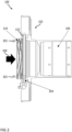
- Fig. 2 shows a schematic sectional view of an embodiment of a cable winch 100.
- the cable winch 100 shown has the emergency braking device 102 at least partially, wherein the cable winch 100 and thus also the emergency braking device of the Fig. 1 described cable winch 100.
- the emergency braking device 102 is shown without the previously described deliverer.
- an effective direction of the direction of movement 200 of the driver 110 in the direction of the cable drum 104 is symbolically shown.
- fastening elements 202 for example screws or rivets, are also shown, which are designed, for example, to fasten the deliverer to the spring unit 124.
- the spring unit 124 is designed as a wave spring.
- the driver 110 also has a stabilization structure 204, by means of which the driver 110 is stabilized in its position, for example.
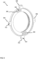
- Fig. 3 shows a schematic representation of a driver 110 according to an embodiment.
- the driver 110 corresponds, for example, to the one shown in at least one of the Figures 1 to 2 described driver 110. According to this embodiment it is clear that the driver 110 is essentially ring-shaped.
- the driver 110 according to this embodiment has at least one projection 300, more precisely two mutually opposite and similarly shaped projections 300.
- the at least one projection 300 is designed to engage in the driver contour.
- the projection 300 also has an elongated through-opening 302.
- the driver 110 has a first holding section 304, a second holding section 306 opposite the first holding section 304, a third holding section 308 arranged between the first holding section 304 and the second holding section 306, and a fourth holding section 310 opposite the third holding section 308.
- the first holding section 304 and the second holding section 306 are optionally designed to be identical.
- the third holding section 308 and the fourth holding section 310 are optionally designed to be identical.
- the first and second holding sections 304, 306 each have an engagement opening 312.
- the third and fourth holding sections 308, 310 each have a receiving opening 314, which is shaped, for example, to insert or screw in a fixing element.
- Fig. 4 shows a schematic representation of a cable drum 104 with a driver contour 400 according to an embodiment.
- the cable drum 104 shown here corresponds, for example, to the one in one of the Figures 1 to 2
- the driver contour 400 is, for example, shaped in such a way that the projections of the driver, as they are, for example, in Fig. 3 described, engage in them.
- the driver contour 400 functions, for example, as a rail in which the driver rotates by a maximum of 180° until it encounters a stop edge 402 of the driver contour 400.
- the driver contour 400 also has a further stop edge 404, which is arranged opposite the stop edge 402.
- the driver contour 400 is formed in steps and from there slopes down until it encounters the further stop edge 404.
- the further stop edge 404 is therefore implemented analogously to the stop edge 402, so that the further stop edge 404 is also formed in steps.
- a number of stop edges 402, 404 on the driver contour 400 is equal to a number of projections on the driver.
- the driver contour 400 is shaped like a ramp.
- the driver contour 400 forms at least one, here two ramps 406.
- the ramp-like shape of the driver contour 400 enables a continuous rotation of the cable drum 104 in one direction of rotation, even if the driver is in the cable drum 104 engages. This enables the cable drum 104 to rotate to pull in the cable even when the emergency braking device is activated. In the opposite direction of rotation, however, the rotation of the cable drum 104 is very quickly stopped by the engagement of the driver and the resulting activation of the braking unit.
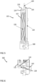
- Fig. 5 shows a schematic sectional view of an embodiment of an arrangement of a deliverer 112 and a driver 110.
- the driver 110 corresponds, for example, to the one shown in one of the Figures 1 to 3
- the carrier 110 described and the deliverer 112 corresponds, for example, to the one in Fig. 1 described feeder 112.
- the spring unit 124 is arranged in the receiving area 122 of the feeder 112, by means of which the driver 110 is pressed into the driver contour of the cable drum.
- the driver 110 and the feeder 112 are connected to one another via the retaining collar 120, which has the connecting structure 116.
- the thread 114 is arranged on the feeder 112, which engages in the counter thread 118.
- a section 500 is marked, which is described in more detail in the following figure.
- Fig. 6 shows a schematic sectional view of a section 500 of an emergency braking device according to an embodiment.
- the section 500 is shown enlarged and corresponds, for example, to the section 500 shown in Fig. 5 mentioned section 500.
- the section 500 therefore corresponds to a contact area in which the driver 110 contacts the feeder 112 and the feeder 112 contacts the thread 114.
- the thread 114 is arranged in such a way that it can act with the counter thread 118 and thus engages in the counter thread 118.
- the thread 114 is temporarily rotating, i.e. starting from an activation of the emergency braking device by engagement of the driver in the cable drum, until the cable drum comes to a standstill.
- the counter thread 118 on the other hand, is fixed, i.e. in particular fixed in relation to the rotation of the cable drum. This enables a screwing movement of the feeder 112 and/or the driver 110 in order to use the brake unit, as used for example in Fig. 1 described to stop the rotation of the rope drum.
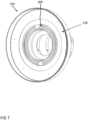
- Fig. 7 shows a schematic representation of a brake pad 128 according to an embodiment.
- the brake pad 128 is arranged on the cable drum 104, which according to an embodiment is at least partially hollow.
- the brake pad 128 is arranged in a ring around the driver contour 400. This means that the brake pad 128 has a larger diameter than the driver structure 400. Examples of cable drums 104 and brake pad 128 are formed in one piece. Alternatively, the brake pad 128 is attached to the cable drum 104.
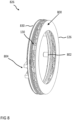
- Fig. 8 shows a schematic representation of a brake package 826 with a spring-loaded brake disk 126 according to an embodiment.
- the brake disk 126 corresponds, for example, to the one shown in Fig. 1 described brake disc 126.
- the further spring unit 130 is designed as part of the brake package 826 between a receptacle 830 and the brake disc 126. More precisely, the further spring unit 130 is arranged on the rear side of a braking surface 800 of the brake disc 126, which in a braking operation on the Fig. 7 shown brake pad is pressed.
- the brake disk 126 has at least one, here two, holding elements on the receptacle 830 according to one embodiment, which are implemented differently.
- a first holding element 802 of the holding elements is pin-like according to this embodiment and a second holding element 804 of the holding elements is shaped as a receptacle, so that, for example, a rotational movement of the brake assembly 826 and thus of the brake disk 126 is prevented.
- the brake disk 126 and the receptacle 830 are shaped like a ring according to this embodiment.
- the spring unit 130 has, according to one embodiment, a plurality of springs which are distributed between the receptacle 830 and the brake disk 126. For example, spiral springs are used as springs.
- the holder 830 and the brake disk 126 are coupled to one another via the spring unit 130 and via a plurality of bolts, which cause a rotational fixation.
- the bolts are attached to the brake disk 126 and free ends of the bolts are received by receiving contours of the holder 830.
- the feeder exerts the activation force on the holder 830 according to one embodiment and moves the holder 830 and thus the entire brake package 826 in the direction of the cable drum.
- the springs of the spring unit 130 are initially compressed when the holder 830 moves further in the direction of the cable drum.
- the braking torque exerted on the cable drum via the brake disk 126 initially increases slowly.
- Fig. 9 shows a schematic representation of an embodiment of a spring-loaded brake disc 126.
- the brake disc 126 is at least similar to the one in Fig. 8 described brake disk 126 and is shown here only from the rear.
- the receptacle 830 optionally has the holding elements 802, 804.
- the brake disk 126 has only two spaced-apart first holding elements 802, which are designed like pins, and the second holding element 804.
- the holding elements 802, 804 are designed as rotation-inhibiting elements that are translationally free.
- Fig. 10 shows a flow chart of an embodiment of a method 1000 for operating an emergency braking device.
- the method 1000 is carried out, for example, for an emergency braking device, as described, for example, in at least one of the Figures 1 to 2
- the method 1000 comprises an engagement step 1002, a transfer step 1004, an effecting step 1006 and an exerting step 1008.
- an engagement of the driver in the driver contour of the cable drum is effected in order to transmit the rotational movement of the cable drum to the driver.
- the rotational movement is transmitted from the driver to the deliverer.
- the linear movement of the deliverer in the direction of the brake unit is effected by the engagement of the thread in the counter thread and by the rotational movement transmitted from the driver to the deliverer.
- a translational force is exerted on the brake unit by the linear movement of the deliverer in order to brake the cable drum using the brake unit.
- the method 1000 further comprises a step 1010 of releasing the emergency braking device using a trigger before the step 1002 of engaging in order to cause the driver to engage in the driver contour.
- a cable for holding back the driver is severed.
- the driver is then moved in the direction of the cable drum, for example driven by a pre-tensioned spring, in order to be able to engage in the cable drum.
Landscapes
- Engineering & Computer Science (AREA)
- Mechanical Engineering (AREA)
- Braking Arrangements (AREA)
Abstract
Description
- Die Erfindung geht von einer Notbremsvorrichtung für eine Seilwinde mit einer um eine Drehachse drehbaren Seiltrommel, einer Seilwinde und einem Verfahren zum Betreiben einer Notbremsvorrichtung nach Gattung der unabhängigen Ansprüche aus.
- Seilwinden werden im Rettungssektor beispielsweise in Verbindung mit Helikoptern als Rettungswinden eingesetzt, die üblicherweise eine "Loss of HEC"-Anforderung der WASA erfüllen. Die
US 5904229 A1 betrifft eine Bremsanordnung, die als automatisch aktivierte Notbremse unter anderem für Hebebühnen und Aufzüge verwendet wird. - Vor diesem Hintergrund werden mit dem hier vorgestellten Ansatz eine verbesserte Notbremsvorrichtung für eine Seilwinde mit einer um eine Drehachse drehbaren Seiltrommel, eine verbesserte Seilwinde sowie ein verbessertes Verfahren zum Betreiben einer Notbremsvorrichtung gemäß den Hauptansprüchen vorgestellt. Durch die in den abhängigen Ansprüchen aufgeführten Maßnahmen sind vorteilhafte Weiterbildungen und Verbesserungen der im unabhängigen Anspruch angegebenen Vorrichtung möglich.
- Der hier vorgestellte Ansatz beschreibt eine Notbremsvorrichtung, die ausgebildet sein kann, um beispielsweise eine fallende Last, beispielsweise eine an einem Seil hängende Person ohne zusätzlich zugeführte Energie bis hin zu einem Stillstand abzubremsen. Auch kann ein ruckartiges Bremsen vermieden werden. Dadurch kann beispielsweise eine auf das Seil wirkende maximale Kraft abgeschwächt werden, bis der Stillstand erreicht wurde. Somit kann beispielsweise eine plötzlich stark ansteigende und auf das Seil wirkende Kraft verringert werden kann.
- Es wird eine Notbremsvorrichtung für eine Seilwinde mit einer um eine Drehachse drehbaren Seiltrommel vorgestellt, wobei die Notbremsvorrichtung eine Bremseinheit aufweist, die ausgebildet ist, um die Seiltrommel abzubremsen, wenn eine Translationskraft auf die Bremseinheit wirkt. Die Notbremsvorrichtung weist zudem einen Mitnehmer auf, der um die Drehachse drehbar und entlang der Drehachse linear beweglich ist und ausgeformt ist, um in einem aktiven Zustand der Notbremsvorrichtung in eine Mitnehmerkontur der Seiltrommel einzugreifen, um eine Drehbewegung der Seiltrommel auf den Mitnehmer zu übertragen, sowie einen Zusteller mit einem Gewinde und einer Verbindungsstruktur, wobei der Zusteller und der Mitnehmer über die Verbindungsstruktur rotationsfest und entlang der Drehachse linear beweglich verbunden sind. Das Gewinde greift dabei in ein Gegengewinde ein, um durch die von dem Mitnehmer auf den Zusteller übertragene Drehbewegung eine Linearbewegung des Zustellers in Richtung der Bremseinheit zu bewirken, um die Translationskraft auf die Bremseinheit auszuüben.
- Die Notbremsvorrichtung kann beispielsweise als eine Einmalbremse bezeichnet werden, die für Notfälle, beispielsweise bei einem unkontrollierten Abseilen, aktiviert wird und somit sicherheitsrelevant sein kann. Die Notbremsvorrichtung kann beispielsweise an einem Helikopter mit der Seilwinde, beispielsweise ein Rettungshubschrauber, angeordnet sein. Die Seilwinde kann dabei ausgeformt sein, um ein Seil abzurollen, sodass beispielsweise Personen und zusätzlich oder alternativ Gegenstände angehoben oder abgelassen werden können. Dazu kann das Seil um die Seiltrommel gewickelt sein. Im inaktiven Zustand der Notbremsvorrichtung kann der Mitnehmer von der Seiltrommel entkoppelt sein, sodass eine Bewegung der Seiltrommel durch die Notbremsvorrichtung nicht behindert wird. Beispielsweise kann der Mitnehmer im inaktiven Zustand unter Verwendung einer Rückhalteeinrichtung entfernt von der Seiltrommel festgehalten werden. Im aktiven Zustand kann der Mitnehmer unter Verwendung einer Feder gegen den Mitnehmer gedrückt werden. Der Zusteller kann beispielsweise unter Verwendung des Gewindes und des Gegengewindes in Richtung der Seiltrommel geschraubt werden und auf diese Weise die Translationskraft auf die Bremseinheit ausüben. Das Gegengewinde kann feststehend ausgeformt sein. Beispielsweise kann das Gegengewinde an einem Gehäuse der Seilwinde oder einer Struktur fix angeordnet sein. Das Gegengewinde kann somit von einer Rotation der Seiltrommel entkoppelt sein, sodass sich die Seiltrommel relativ zu dem Gegengewinde drehen kann. Die Bremseinheit kann die Seiltrommel unter Verwendung der Translationskraft abbremsen, die somit als Bremskraft wirken kann. Eine Größe der Translationskraft kann vorteilhafterweise mit einem auf die Seiltrommel wirkenden Drehmoment zusammenhängen, das beispielsweise von einer fallenden Last hervorgerufen wird. Somit kann die Translationskraft von einer Drehgeschwindigkeit der Seiltrommel abhängen, sodass die Translationskraft in jedem Fall ausreichen kann, um die Seiltrommel abzubremsen. Der Mitnehmer kann vorteilhafterweise formschlüssig in die Mitnehmerkontur eingreifen, sodass diese beiden Komponenten fest miteinander verbunden sein können.
- Die Notbremsvorrichtung kann für verschiedene Einsatzmöglichkeiten vorgesehen werden, bei denen rotierende Dinge bis zum Halt (Not-Halt) angehalten werden müssen. Somit steht die genannte Seiltrommel stellvertretend für ein rotierendes Teil, das durch die Notbremsvorrichtung angehalten werden kann.
- Gemäß einer Ausführungsform kann der Zusteller einen Haltekragen mit der Verbindungsstruktur und einen Aufnahmeabschnitt zum Aufnehmen einer Federeinheit aufweisen, wobei die Federeinheit in einem inaktiven Zustand der Notbremsvorrichtung gesichert sein kann. Die Federeinheit kann im aktiven Zustand der Notbremsvorrichtung entsichert sein, um den Mitnehmer entlang der Drehachse in die Mitnehmerkontur drücken zu können. Die Verbindungsstruktur kann demnach in dem Haltekragen realisiert sein, beispielsweise als Durchgangsöffnung oder als eine Ausnehmung. Der Aufnahmeabschnitt kann als eine nischenartige Ausnehmung ausgeführt sein, sodass die Federeinheit in diese hineinpasst. Die entsicherte Federeinheit kann vorteilhafterweise die Linearbewegung des Mitnehmers bewirken, um den Mitnehmer rotationsfest mit der Seiltrommel zu verbinden.
- Beispielsweise kann der Mitnehmer im inaktiven Zustand der Notbremsvorrichtung unter Verwendung eines Seils, beispielsweise eines Stahlseils, zurückgehalten werden. Das Seil kann dabei einer vorgespannten Wellenfeder entgegenwirken, die bei einem Durchtrennen des Seils den Mitnehmer gegen die Seiltrommel drücken kann.
- Die Notbremsvorrichtung kann gemäß einer Ausführungsform einen Auslöser aufweisen, der ausgebildet sein kann, um die Federeinheit zu entsichern. Der Auslöser kann beispielsweise manuell durch einen Nutzer oder automatisiert beispielsweise bei Überschreiten einer Drehgeschwindigkeit der Seiltrommel betätigt werden. Beispielsweise kann der Auslöser eine Pyrotechnik umfassen, mit der eine Rückhalteeinrichtung zum Zurückhalten des Mitnehmers zerstört wird. Beispielsweise kann ein Seil zum Zurückhalten des Mitnehmers unter Verwendung des Auslösers durchtrennt werden. Vorteilhafterweise kann die Notbremsvorrichtung als Sicherheitskomponente bezeichnet werden, die ausgebildet sein kann, um Personen zu schützen.
- Gemäß einer Ausführungsform kann die Bremseinheit eine Bremsscheibe und einen Bremsbelag umfassen, wobei die Bremsscheibe ausgeformt sein kann, um unter Verwendung der Translationskraft gegen den Bremsbelag gedrückt zu werden, um die Seiltrommel abzubremsen. Die Translationskraft kann vorteilhafterweise von der Drehgeschwindigkeit und zusätzlich oder alternativ von der fallenden Last abhängig sein, das bedeutet der an dem Seil hängenden Person, sodass die Seiltrommel abgebremst werden kann.
- Weiterhin kann der Zusteller ausgeformt sein, um die Bremsscheibe gegen den Bremsbelag drücken zu können. Das bedeutet, dass die Bremsscheibe auf den Bremsbelag gepresst werden kann und durch die entstehende Reibkraft die Drehbewegung der Seiltrommel abgebremst und schließlich gestoppt werden kann.
- Gemäß einer Ausführungsform kann der Bremsbelag starr mit der Seiltrommel verbunden sein. Beispielsweise kann der Bremsbelag als ein ringförmiger Fortsatz der Seiltrommel ausgeformt sein.
- Die Bremseinheit kann ein Bremspaket aufweisen, das die Bremsscheibe, eine Aufnahme und eine zwischen der Bremsscheibe und der Aufnahme angeordnete weitere Federeinheit umfasst. Unter Verwendung der weiteren Federeinheit kann ein ruckartiges Stoppen der Seiltrommel vermieden werden. Vorteilhafterweise kann der Bremsvorgang so für eine an dem Seil hängende Person angenehmer empfunden werden, da durch die Federeinheit die Bremswirkung abgemildert wird.
- Gemäß einer Ausführungsform kann der Mitnehmer mindestens einen Vorsprung aufweisen, der ausgebildet sein kann, um in die Mitnehmerkontur einzugreifen. Der Vorsprung kann beispielsweise als Halteelement bezeichnet werden und kann beispielsweise als ein Zahn ausgeformt sein, der in die Mitnehmerkontur greifen kann. Die Mitnehmerkontur kann zumindest eine Rampe ausformen. Vorteilhafterweise kann dadurch ein Eingreifen des Mitnehmer in die Mitnehmerkontur verhindert werden, wenn sich die Seiltrommel in einer Drehrichtung zum Rufrollen des Seils bewegt.
- Ferner wird eine Seilwinde mit einer um eine Drehachse drehbaren Seiltrommel und mit einer Notbremsvorrichtung in einer zuvor genannten Variante vorgestellt.
- Die Seilwinde kann vorteilhafterweise für Rettungshubschrauber realisiert sein, wie sie beispielsweise im Gebirge oder zu Wasser eingesetzt werden. Die Seiltrommel kann vorteilhafterweise ausgeformt sein, um ein Rettungsseil aufzuwickeln und zusätzlich oder alternativ abzuwickeln. Die Seiltrommel kann dazu um die Drehachse beweglich angeordnet sein.
- Weiterhin wird ein Verfahren zum Betreiben einer Notbremsvorrichtung in einer zuvor genannten Variante vorgestellt. Das Verfahren umfasst einen Schritt des Eingreifens des Mitnehmers in die Mitnehmerkontur der Seiltrommel, um die Drehbewegung der Seiltrommel auf den Mitnehmer zu übertragen, einen Schritt des Übertragens der Drehbewegung von dem Mitnehmer auf den Zusteller sowie einen Schritt des Bewirkens der Linearbewegung des Zustellers in Richtung der Bremseinheit durch das Eingreifen des Gewindes in das Gegengewinde und durch die von dem Mitnehmer auf den Zusteller übertragene Drehbewegung und einen Schritt des Ausübens einer Translationskraft auf die Bremseinheit durch die Linearbewegung des Zustellers, um die Seiltrommel unter Verwendung der Bremseinheit abzubremsen.
- Durch das Verfahren kann vorteilhafterweise Seilwinde für Notfälle abgesichert werden, sodass die Seiltrommel unter Verwendung der Notbremsvorrichtung bei beispielsweise einem unkontrollierten Abseilen abgebremst und in einen Stillstand versetzt werden kann.
- Gemäß einer Ausführungsform kann das Verfahren einen Schritt des Entsicherns der Notbremsvorrichtung unter Verwendung eines Auslösers umfassen, um das Eingreifen des Mitnehmers in die Mitnehmerkontur bewirken zu können. Beispielsweise kann durch den Schritt des Entsicherns die Notbremsvorrichtung aktiviert werden.
- Ausführungsbeispiele des hier vorgestellten Ansatzes sind in den Zeichnungen dargestellt und in der nachfolgenden Beschreibung näher erläutert. Es zeigt:
-
Fig. 1 eine schematische Schnittdarstellung einer Seilwinde mit einer Notbremsvorrichtung gemäß einem Ausführungsbeispiel; -
Fig. 2 eine schematische Schnittdarstellung eines Ausführungsbeispiels einer Seilwinde; -
Fig. 3 eine schematische Darstellung eines Mitnehmers gemäß einem Ausführungsbeispiel; -
Fig. 4 eine schematische Darstellung einer Seiltrommel mit einer Mitnehmerkontur gemäß einem Ausführungsbeispiel; -
Fig. 5 eine schematische Schnittdarstellung eines Ausführungsbeispiels einer Anordnung eines Zustellers und eines Mitnehmers; -
Fig. 6 eine schematische Schnittdarstellung eines Abschnitts einer Notbremsvorrichtung gemäß einem Ausführungsbeispiel; -
Fig. 7 eine schematische Darstellung eines Bremsbelags gemäß einem Ausführungsbeispiel; -
Fig. 8 eine schematische Darstellung einer federgelagerten Bremsscheibe gemäß einem Ausführungsbeispiel; -
Fig. 9 eine schematische Darstellung eines Ausführungsbeispiels einer federgelagerten Bremsscheibe; und -
Fig. 10 ein Ablaufdiagramm eines Ausführungsbeispiels eines Verfahrens zum Betreiben einer Notbremsvorrichtung. - In der nachfolgenden Beschreibung günstiger Ausführungsbeispiele der vorliegenden Erfindung werden für die in den verschiedenen Figuren dargestellten und ähnlich wirkenden Elemente gleiche oder ähnliche Bezugszeichen verwendet, wobei auf eine wiederholte Beschreibung dieser Elemente verzichtet wird.
-
Fig. 1 zeigt eine schematische Schnittdarstellung einer Seilwinde 100 mit einer Notbremsvorrichtung 102 gemäß einem Ausführungsbeispiel. Die Seilwinde 100 ist beispielsweise in oder an einem Helikopter, beispielsweise einen Rettungshubschrauber, angeordnet. Gemäß diesem Ausführungsbeispiel ist die Seilwinde 100 in einem Längsschnitt dargestellt und weist die Notbremsvorrichtung 102 sowie ein rotierendes Teil, beispielhaft in Form einer Seiltrommel 104, auf. Die Seiltrommel 104 ist dabei ausgebildet, um beispielsweise ein Seil auf- oder abzuwickeln und ist demnach um eine Drehachse 106 drehbar. Auch wenn die Erfindung hier anhand einer Seilwinde 100 beschrieben wird, kann die Notbremsvorrichtung 102 auch zum Bremsen anderer rotierender Teile, beispielsweise eines rotierenden Maschinenteils einer Arbeitsmaschine, verwendet werden. In so einem Fall kann die Seiltrommel 104 beispielsweise als Abschnitt einer Welle aufgefasst werden. - Die Notbremsvorrichtung 102 wird beispielsweise auch als Arrestor bezeichnet und weist eine Bremseinheit 108, einen Mitnehmer 110 sowie einen Zusteller 112 auf. Die Bremseinheit 108 ist dabei ausgebildet, um die Seiltrommel 104 abzubremsen, wenn eine Translationskraft auf die Bremseinheit 108 wirkt. Die Bremseinheit 108 oder mindestens Teile davon sind beispielsweise an einem Gehäuse angeordnet oder anordenbar. Der Mitnehmer 110 ist um die Drehachse 106 drehbar und entlang der Drehachse 106 linear beweglich angeordnet.
- Der Mitnehmer 110 ist ausgeformt, um in einem auch als Bremszustand bezeichneten aktiven Zustand der Notbremsvorrichtung 102 in eine Mitnehmerkontur der Seiltrommel 104 einzugreifen, um eine Drehbewegung der Seiltrommel 104 auf den Mitnehmer 110 zu übertragen. Der Mitnehmer 110 ist weiterhin mit dem Zusteller 112 rotationsfest und entlang der Drehachse 106 linear, das heißt in Richtung der Seiltrommel 104 beweglich verbunden. Der Zusteller 112 weist dazu ein Gewinde 114 und eine Verbindungsstruktur 116 auf. Über die beispielsweise als Durchgangsöffnung ausgeformte Verbindungsstruktur 116 ist der Zusteller 112 mit dem Mitnehmer 110 gekoppelt. Das Gewinde 114 greift dabei in ein feststehendes, von einer Rotation der Seiltrommel 104 entkoppeltes, Gegengewinde 118 ein. Eine von der Seiltrommel 104 über den Mitnehmer 110 auf das Gewinde 114 übertragenes Drehmoment, führt somit zu einer Drehung des Gewindes 114 in dem Gegengewinde 118. Daraus resultiert eine Linearbewegung des Zustellers 112 in Richtung der Seiltrommel 104 und somit in Richtung der Bremseinheit 108, wodurch die Translationskraft auf die Bremseinheit 108 ausgeübt werden kann. Das bedeutet, dass sich die Notbremsvorrichtung 102 unter Verwendung des Gewindes 114 und des Gegengewindes 118 einschraubt, wenn eine Last, beispielsweise eine an einem Seil hängende Person, fällt. Durch die Notbremsvorrichtung 102, genauer gesagt durch die Bremseinheit 108 wird die Last, die als Translationskraft auf die Bremseinheit 108 wirkt, abgefangen und die Drehbewegung gestoppt.
- Vorteilhafterweise wird über das Gewinde 114 und des Gegengewindes 118 Energie eines rotierenden Teils, hier beispielsweise der Seiltrommel 104 aufgenommen und zum Abbremsen des rotierenden Teils verwendet. Wenn das Gewinde 114 und das Gegengewinde 118 schwergängig ausgeführt sind, kann bereits über das Gewinde 114 und das Gegengewinde 118 Energie des rotierenden Teils in Wärmeenergie umgewandelt werden und das rotierende Teil dadurch bereits etwas abgebremst werden.
- Gemäß einem Ausführungsbeispiel weist der Zusteller 110 einen ringförmigen Haltekragen 120 auf, an dem die Verbindungsstruktur 116 angeordnet oder in den sie integriert ist. Gemäß einem Ausführungsbeispiel weist der Zusteller 112 einen Aufnahmeabschnitt 122 auf, der ausgebildet ist, um eine Federeinheit 124 aufzunehmen. Die Federeinheit 124 ist weiterhin in einem inaktiven Zustand der Notbremsvorrichtung 100 gesichert und im aktiven Zustand der Notbremsvorrichtung 100 entsichert, um den Mitnehmer 110 entlang der Drehachse 106 in die Mitnehmerkontur zu drücken. Lediglich optional weist die Notbremsvorrichtung 100 einen Auslöser auf, der ausgebildet ist, um die Federeinheit 124 zu entsichern. Der Auslöser wird beispielsweise manuell durch einen Nutzer oder maschinell beispielsweise bei einem Überschreiten der Drehgeschwindigkeit der Seiltrommel 104 betätigt. Beispielsweise umfasst der Auslöser eine Pyrotechnik, die verwendet wird, um den vorgespannten Mitnehmer 110 freizugeben. Nach Freigabe des Mitnehmer 110 kann unter Verwendung der Notbremseinrichtung 102 ein ungewolltes Abrollen des Seils von der Seiltrommel 104 zuverlässig verhindert werden.
- Die Bremseinheit 108 weist gemäß einem Ausführungsbeispiel eine Bremsscheibe 126 und einen Bremsbelag 128 auf. Die Bremsscheibe 126 ist dabei ausgeformt, um unter Verwendung der Translationskraft auf den Bremsbelag 128 zu wirken. Anders ausgedrückt wird die Bremsscheibe 126 auf den Bremsbelag 128 gepresst und die dadurch entstehende Reibkraft führt zum abbremsen der Drehbewegung der Seiltrommel 104. Gemäß diesem Ausführungsbeispiel ist der Zusteller 112 demnach ausgeformt, um die Bremsscheibe 126 auf den Bremsbelag 128 zu pressen. Dies erfolgt beispielsweise mittels einer Verbindungsstelle des Zustellers 112 und der Bremseinheit 108 im Bereich des Haltekragens 120. Insgesamt ist die Bremseinheit 108 gemäß diesem Ausführungsbeispiel ringartig ausgeführt. Gemäß einem Ausführungsbeispiel ist die Bremsscheibe 126 von der Rotation der Seiltrommel 104 entkoppelt ausgeführt, dreht sich also nicht mit der Seiltrommel 104 mit. Der Bremsbelag 128 ist dagegen starr mit der Seiltrommel 104 gekoppelt und dreht sich entsprechend mit der Seiltrommel 104 mit. Gemäß einem Ausführungsbeispiel ist die Bremsscheibe 126 mit einer weiteren Federeinheit 130 gekoppelt, die derart ausgeführt ist, dass sie der Translationskraft mindestens teilweise entgegenwirkt, um ein ruckartiges Stoppen der Seiltrommel 104 zu vermeiden. Stattdessen wird unter Verwendung der weiteren Federeinheit 130 ein vergleichsweise sanftes Abbremsen bewirkt, sodass beispielsweise das Seil und die Person im Bremsvorgang geschont werden. Anders ausgedrückt wirkt die Federkraft entgegen der Translationskraft.
- Gemäß einem Ausführungsbeispiel ist die Notbremsvorrichtung 102 als Arrestor, das bedeutet als Notbremse, ohne Energiespeicher ausgeführt. Die Notbremsvorrichtung 102 ist ausgebildet, um die Seiltrommel 104 bei unkontrolliert ablaufendem Seil zu stoppen. Lediglich optional ist die Seiltrommel 104 als ein Direktwickler oder beispielsweise als eine Capstan-Winde realisiert und wird mittels der Notbremsvorrichtung 102 zum Stehen gebracht. Die Nutzung der Rotationsenergie der Seiltrommel 104 und der fallenden Last sorgt dafür, dass für jede fallende Last der entsprechende Bremsdruck, der hier als Translationskraft beschrieben ist, bis hin zu einem Stillstand oder Halt erzeugt wird.
- Es handelt sich anders ausgedrückt um eine Bremse, welche die Energie der rotierenden Seiltrommel 104 nutzt, um mittels des Gewindes 114 zu schließen. Der Reibschluss wird dabei von der Energie der rotierenden Seiltrommel 104 und der fallenden Last hergestellt und ist damit so groß, dass die Seiltrommel 104 und damit auch die fallende Last zum Stillstand kommt. Die Bremse ist dabei als eine Einmalbremse ausgeformt. Sie ist nicht ohne Weiteres zu öffnen, sodass sie als Sicherheitselement realisiert oder realisierbar ist.
- Der gemäß einem Ausführungsbeispiel federbelasteter Mitnehmer 110 wird dazu in Eingriff mit der Mitnehmerstruktur gebracht und beispielsweise unter Verwendung eines Auslösers freigegeben. Damit wird die Rotation aufgenommen. Der Mitnehmer 110 überträgt die Rotation nun auf den Zusteller 112, wobei Mitnehmer 110 und Zusteller 112 rotationsfest miteinander verbunden sind. Da der Zusteller 112 das Gewinde 114 auf der auch als Rotationsachse bezeichneten Drehachse 106 besitzt und das Gegengewinde 118 unbeweglich in Bezug zu der Drehung des Zustellers 112 ist, führt diese Rotation zu einer Translation des Zustellers 112.
- Die Translation schiebt die rotationsfreie Bremsscheibe 126, die federgelagert realisiert ist, um Bremskraft nicht zu plötzlich zu stark ansteigen zu lassen, gegen den Bremsbelag 128 an der Seiltrommel 104. Je weiter die Seiltrommel 104 dabei dreht, desto größer wird die Presskraft zwischen den Bremsflächen, die hier als die Bremsscheibe 126 und der Bremsbelag 128 beschrieben sind. Der Reibschluss zwischen Bremsscheibe 126 und Bremsbelag 128 führt dabei zum Stillstand der Seiltrommel 104.
-
Fig. 2 zeigt eine schematische Schnittdarstellung eines Ausführungsbeispiels einer Seilwinde 100. Die inFig. 2 dargestellte Seilwinde 100 weist die Notbremsvorrichtung 102 mindestens teilweise auf, wobei die Seilwinde 100 und demnach auch die Notbremsvorrichtung der inFig. 1 beschriebenen Seilwinde 100 mindestens ähnelt. Gemäß diesem Ausführungsbeispiel ist die Notbremsvorrichtung 102 ohne den zuvor beschriebenen Zusteller dargestellt. Stattdessen ist gemäß diesem Ausführungsbeispiel eine Wirkrichtung der Bewegungsrichtung 200 des Mitnehmers 110 in Richtung der Seiltrommel 104 symbolisch dargestellt. Gemäß diesem Ausführungsbeispiel sind weiterhin Befestigungselemente 202, beispielsweise Schrauben oder Nieten, dargestellt, die beispielsweise ausgebildet sind, um den Zusteller an der Federeinheit 124 zu befestigen. Beispielhaft ist die Federeinheit 124 als eine Wellenfeder ausgeführt. Der Mitnehmer 110 weist weiterhin eine Stabilisierungsstruktur 204 auf, durch die der Mitnehmer 110 beispielsweise in seiner Position stabilisiert wird. -
Fig. 3 zeigt eine schematische Darstellung eines Mitnehmers 110 gemäß einem Ausführungsbeispiel. Der Mitnehmer 110 entspricht beispielsweise dem in mindestens einer derFiguren 1 bis 2 beschriebenen Mitnehmer 110. Gemäß diesem Ausführungsbeispiel ist verdeutlicht, dass der Mitnehmer 110 im Wesentlichen ringartig ausgeformt ist. Weiterhin weist der Mitnehmer 110 gemäß diesem Ausführungsbeispiel mindestens einen Vorsprung 300, genauer gesagt zwei einander gegenüberliegende und gleichartig ausgeformte Vorsprünge 300 auf. Der mindestens eine Vorsprung 300 ist dabei ausgebildet, um in die Mitnehmerkontur einzugreifen. Der Vorsprung 300 weist weiterhin eine längliche Durchgangsöffnung 302 auf. Ferner weist der Mitnehmer 110 gemäß diesem Ausführungsbeispiel einen ersten Halteabschnitt 304, einen dem ersten Halteabschnitt 304 gegenüberliegenden zweiten Halteabschnitt 306, einen zwischen dem ersten Halteabschnitt 304 und dem zweiten Halteabschnitt 306 angeordneten dritten Halteabschnitt 308 und einen dem dritten Halteabschnitt 308 gegenüberliegenden vierten Halteabschnitt 310 auf. Dabei sind der erste Halteabschnitt 304 und der zweite Halteabschnitt 306 optional gleichartig ausgeführt. Weiterhin sind der dritte Halteabschnitt 308 und der vierte Halteabschnitt 310 optional gleichartig ausgeführt. Gemäß diesem Ausführungsbeispiel weisen der erste und der zweite Halteabschnitt 304, 306 jeweils eine Eingriffsöffnung 312 auf. Der dritte und der vierte Halteabschnitt 308, 310 weisen im Gegensatz dazu jeweils eine Aufnahmeöffnung 314 auf, die beispielsweise ausgeformt ist, um ein Fixierelement einzuschieben oder einzuschrauben. -
Fig. 4 zeigt eine schematische Darstellung einer Seiltrommel 104 mit einer Mitnehmerkontur 400 gemäß einem Ausführungsbeispiel. Die hier dargestellte Seiltrommel 104 entspricht beispielsweise der in einer derFiguren 1 bis 2 beschriebenen Seiltrommel 104. Die Mitnehmerkontur 400 ist beispielsweise derart ausgeformt, dass die Vorsprünge des Mitnehmers, wie sie beispielsweise inFig. 3 beschrieben wurden, in sie eingreifen. Die Mitnehmerkontur 400 fungiert beispielsweise als eine Schiene, in der sich der Mitnehmer um höchstens 180° dreht, bis er auf eine Stoppkante 402 der Mitnehmerkontur 400 trifft. Optional weist die Mitnehmerkontur 400 zusätzlich eine weitere Stoppkante 404 auf, die der Stoppkante 402 gegenüberliegend angeordnet ist. Im Bereich der Stoppkante 402 ist die Mitnehmerkontur 400 stufenartig ausgeformt und fällt ab dort so lange ab, bis sie auf die weitere Stoppkante 404 trifft. Die weitere Stoppkante 404 demnach analog zu der Stoppkante 402 realisiert, sodass die weitere Stoppkante 404 ebenfalls stufenartig ausgeformt ist. Insgesamt betrachtet ist eine Anzahl der Stoppkanten 402, 404 an der Mitnehmerkontur 400 gleich einer Anzahl von Vorsprüngen an dem Mitnehmer. - Gemäß einem Ausführungsbeispiel ist die Mitnehmerkontur 400 rampenartig ausgeformt. Beispielhaft formt die Mitnehmerkontur 400 zumindest eine, hier zwei Rampen 406 aus. Die rampenartige Ausformung der Mitnehmerkontor 400 ermöglicht eine durchgängige Drehung der Seiltrommel 104 in einer Drehrichtung, auch wenn der Mitnehmer in die Seiltrommel 104 eingreift. Dies ermöglicht auch bei aktivierter Notbremsvorrichtung eine Drehung der Seiltrommel 104 zum Einholen des Seils. In die entgegengesetzte Drehrichtung wird die Drehung der Seiltrommel 104 dagegen durch das Eingreifen des Mitnehmers und die daraus resultierende Aktivierung der Bremseinheit sehr schnell unterbunden.
-
Fig. 5 zeigt eine schematische Schnittdarstellung eines Ausführungsbeispiels einer Anordnung eines Zustellers 112 und eines Mitnehmers 110. Der Mitnehmer 110 entspricht dabei beispielsweise dem in einer derFiguren 1 bis 3 beschriebenen Mitnehmer 110 und der Zusteller 112 entspricht beispielsweise dem inFig. 1 beschriebenen Zusteller 112. Auch hier ist die Federeinheit 124 im Aufnahmebereich 122 des Zustellers 112 angeordnet, durch welche der Mitnehmer 110 in die Mitnehmerkontur der Seiltrommel gedrückt wird. Der Mitnehmer 110 und der Zusteller 112 sind auch hier über den Haltekragen 120 miteinander verbunden, der die Verbindungsstruktur 116 aufweist. Auch hier ist an dem Zusteller 112 das Gewinde 114 angeordnet, das in das Gegengewinde 118 eingreift. Gemäß diesem Ausführungsbeispiel ist ein Abschnitt 500 markiert, der in der nachfolgenden Figur näher beschrieben wird. -
Fig. 6 zeigt eine schematische Schnittdarstellung eines Abschnitts 500 einer Notbremsvorrichtung gemäß einem Ausführungsbeispiel. Der Abschnitt 500 ist dabei vergrößert dargestellt und entspricht beispielsweise dem inFig. 5 erwähnten Abschnitt 500. Der Abschnitt 500 entspricht demnach einem Kontaktbereich, in dem der Mitnehmer 110 den Zusteller 112 und der Zusteller 112 das Gewinde 114 kontaktiert. Weiterhin ist das Gewinde 114 derart angeordnet, dass es mit dem Gegengewinde 118 wirken kann und demnach in das Gegengewinde 118 greift. Das Gewinde 114 ist zeitweise rotierend, also ausgehend von einer Aktivierung der Notbremsvorrichtung durch Eingriff des Mitnehmers in die Seiltrommel, bist zu einem Stillstand der Seiltrommel. Das Gegengewinde 118 ist dagegen fest, also insbesondere feststehend in Bezug zu der Drehung der Seiltrommel. Dadurch wird eine Schraubbewegung des Zustellers 112 und/oder des Mitnehmers 110 ermöglicht, um unter Verwendung der Bremseinheit, wie sie beispielsweise inFig. 1 beschrieben wurde, die Drehbewegung der Seiltrommel zu stoppen. -
Fig. 7 zeigt eine schematische Darstellung eines Bremsbelags 128 gemäß einem Ausführungsbeispiel. Der Bremsbelag 128 ist gemäß diesem Ausführungsbeispiel an der Seiltrommel 104 angeordnet, die gemäß einem Ausführungsbeispiel mindestens teilweise hohl ausgeführt ist. Gemäß diesem Ausführungsbeispiel ist der Bremsbelag 128 ringförmig um die Mitnehmerkontur 400 herum angeordnet. Das bedeutet, dass der Bremsbelag 128 einen größeren Durchmesser aufweist als die Mitnehmerstruktur 400. Beispielshaft sind Seiltrommel 104 und Bremsbelag 128 einstückig ausgeformt. Alternativ ist der Bremsbelag 128 an der Seiltrommel 104 befestigt. -
Fig. 8 zeigt eine schematische Darstellung eines Bremspakets 826 mit einer federgelagerten Bremsscheibe 126 gemäß einem Ausführungsbeispiel. Die Bremsscheibe 126 entspricht beispielsweise der inFig. 1 beschriebenen Bremsscheibe 126. Gemäß diesem Ausführungsbeispiel ist die weitere Federeinheit 130 als Teil des Bremspakets 826 zwischen einer Aufnahme 830 und der Bremsscheibe 126 ausgeführt. Genauer gesagt ist die weitere Federeinheit 130 rückseitig einer Bremsfläche 800 der Bremsscheibe 126 angeordnet, welche in einem Bremsvorgang auf den inFig. 7 gezeigten Bremsbelag gedrückt wird. Rückseitig weist die Bremsscheibe 126 gemäß einem Ausführungsbeispiel an der Aufnahme 830 mindestens ein, hier zwei Halteelemente auf, die unterschiedlich realisiert sind. Ein erstes Halteelement 802 der Halteelemente ist gemäß diesem Ausführungsbeispiel stiftartig und ein zweites Halteelement 804 der Halteelemente ist als eine Aufnahme ausgeformt, sodass beispielsweise eine Drehbewegung des Bremspakets 826 und somit der Bremsscheibe 126 verhindert wird. Die Bremsscheibe 126 und die Aufnahme 830 sind gemäß diesem Ausführungsbeispiel ringartig ausgeformt. Die Federeinheit 130 weist gemäß einem Ausführungsbeispiel eine Mehrzahl von Federn auf, die zwischen der Aufnahme 830 und der Bremsscheibe 126 verteilt angeordnet sind. Beispielsweise werden als Federn Spiralfedern verwendet. - Die Aufnahme 830 und die Bremsscheibe 126 sind zum einen über die Federeinheit 130 und zum anderen über eine Mehrzahl von Bolzen miteinander gekoppelt, die eine rotatorische Festsetzung bewirken. Beispielhaft sind die Bolzen an der Bremsscheibe 126 befestigt und freie Enden der Bolzen sind von Aufnahmekonturen der Aufnahme 830 aufgenommen.
- Wenn der Zusteller aufgrund der Relativbewegung zwischen Gewinde und Gegengewinde wie beschrieben translatorisch bewegt wird, übt der Zusteller gemäß einem Ausführungsbeispiel die Aktivierungskraft auf die die Aufnahme 830 aus und verschiebt die Aufnahme 830 und damit das gesamte Bremspaket 826 in Richtung der Seiltrommel. Sobald die Bremsscheibe 126 die Seiltrommel berührt, werden bei einer weiteren Bewegung der Aufnahme 830 in Richtung der Seiltrommel zunächst die Federn der Federeinheit 130 gestaucht. Dadurch steigt das über die Bremsscheibe 126 auf die Seiltrommel ausgeübte Bremsmoment anfangs langsam an. Durch eine geeignete Auslegung der Federeinheit 130, die auch als Federpaket bezeichnet werden kann, kann dadurch gesteuert werden, wie schnell die Bremswirkung der Notbremsvorrichtung ansteigt.
-
Fig. 9 zeigt eine schematische Darstellung eines Ausführungsbeispiels einer federgelagerten Bremsscheibe 126. Die Bremsscheibe 126 ähnelt mindestens der inFig. 8 beschriebenen Bremsscheibe 126 und ist hier lediglich rückseitig dargestellt. Auch gemäß diesem Ausführungsbeispiel weist die Aufnahme 830 optional die Halteelemente 802, 804 auf. Gemäß diesem Ausführungsbeispiel weist die Bremsscheibe 126 lediglich zwei voneinander beabstandete erste Halteelemente 802, die stiftartig ausgeführt sind, und das zweite Halteelement 804 auf. Die Halteelemente 802, 804 sind als rotations-hemmende Elemente translatorisch frei ausgeführt. -
Fig. 10 zeigt ein Ablaufdiagramm eines Ausführungsbeispiels eines Verfahrens 1000 zum Betreiben einer Notbremsvorrichtung. Das Verfahren 1000 wird beispielsweise für eine Notbremsvorrichtung durchgeführt, wie sie beispielsweise in mindestens einer derFiguren 1 bis 2 beschrieben wurde. Das Verfahren 1000 umfasst dazu einen Schritt 1002 des Eingreifens, einen Schritt 1004 des Übertragens, einen Schritt 1006 des Bewirkens und einen Schritt 1008 des Ausübens. Im Schritt 1002 des Eingreifens wird ein Eingreifen des Mitnehmers in die Mitnehmerkontur der Seiltrommel bewirkt, um die Drehbewegung der Seiltrommel auf den Mitnehmer zu übertragen. Im Schritt 1004 des Übertragens wird die Drehbewegung von dem Mitnehmer auf den Zusteller übertragen. Im Schritt 1006 des Bewirkens wird die Linearbewegung des Zustellers in Richtung der Bremseinheit durch das Eingreifen des Gewindes in das Gegengewinde und durch die von dem Mitnehmer auf den Zusteller übertragene Drehbewegung bewirkt. Im Schritt 1008 des Ausübens wird eine Translationskraft auf die Bremseinheit durch die Linearbewegung des Zustellers ausgeübt, um die Seiltrommel unter Verwendung der Bremseinheit abzubremsen. - Lediglich optional umfasst das Verfahren 1000 weiterhin einen Schritt 1010 des Entsicherns der Notbremsvorrichtung unter Verwendung eines Auslösers vor dem Schritt 1002 des Eingreifens, um das Eingreifen des Mitnehmers in die Mitnehmerkontur zu bewirken. Beispielsweise wird dabei ein Seil zum Zurückhalten des Mitnehmers durchtrennt. Anschließend wird der Mitnehmer beispielsweise getrieben von einer vorgespannten Feder in Richtung der Seiltrommel bewegt, um in die Seiltrommel eingreifen zu können.
Claims (9)
- Notbremsvorrichtung (102) für eine Seilwinde (102) mit einer um eine Drehachse (106) drehbaren Seiltrommel (104), wobei die Notbremsvorrichtung (102) die folgenden Merkmale aufweist:eine Bremseinheit (108), die ausgebildet ist, um die Seiltrommel (104) abzubremsen, wenn eine Translationskraft auf die Bremseinheit (108) wirkt;einen Mitnehmer (110), der um die Drehachse (106) drehbar und entlang der Drehachse (106) linear beweglich ist und ausgeformt ist, um in einem aktiven Zustand der Notbremsvorrichtung (102) in eine Mitnehmerkontur (400) der Seiltrommel (104) einzugreifen, um eine Drehbewegung der Seiltrommel (104) auf den Mitnehmer (110) zu übertragen; undeinen Zusteller (112) mit einem Gewinde (114) und einer Verbindungsstruktur (116), wobei der Zusteller (112) und der Mitnehmer (110) über die Verbindungsstruktur (116) rotationsfest und entlang der Drehachse (106) linear beweglich verbunden sind, und wobei das Gewinde (114) in ein Gegengewinde (118) eingreift, um durch die von dem Mitnehmer (110) auf den Zusteller (112) übertragene Drehbewegung eine Linearbewegung des Zustellers (112) in Richtung der Bremseinheit (108) zu bewirken, um die Translationskraft auf die Bremseinheit (108) auszuüben,dadurch gekennzeichnet, dassder Mitnehmer (110) mindestens einen Vorsprung (300) aufweist, der ausgebildet ist, um in die Mitnehmerkontur (400) einzugreifen, wobei die Mitnehmerkontur (400) zumindest eine Rampe (406) ausformt.
- Notbremsvorrichtung (102) gemäß Anspruch 1, wobei der Zusteller (112) einen Haltekragen (120) mit der Verbindungsstruktur (116) und einen Aufnahmeabschnitt (122) zum Aufnehmen einer Federeinheit (124) aufweist, wobei die Federeinheit (124) in einem inaktiven Zustand der Notbremsvorrichtung (102) gesichert ist, und wobei die Federeinheit (124) im aktiven Zustand der Notbremsvorrichtung (102) entsichert ist, um den Mitnehmer (110) entlang der Drehachse (106) in die Mitnehmerkontur (400) zu drücken.
- Notbremsvorrichtung (102) gemäß Anspruch 2, mit einem Auslöser, der ausgebildet ist, um die Federeinheit (124) zu entsichern.
- Notbremsvorrichtung (102) gemäß einem der vorangegangenen Ansprüche, wobei die Bremseinheit (108) eine Bremsscheibe (126) und einen Bremsbelag (128) umfasst, wobei die Bremsscheibe (126) unter Verwendung der Translationskraft gegen den Bremsbelag (128) gedrückt wird, um die Seiltrommel (104) abzubremsen.
- Notbremsvorrichtung (102) gemäß Anspruch 4, wobei der Bremsbelag (128) starr mit der Seiltrommel (104) verbunden ist.
- Notbremsvorrichtung (102) gemäß einem der Ansprüche 4 bis 5, wobei die Bremseinheit (108) ein Bremspaket (826) aufweist, das die Bremsscheibe (126), eine Aufnahme (830) und eine zwischen der Bremsscheibe (126) und der Aufnahme angeordnete weitere Federeinheit (130) zum Vermeiden eines ruckartigen Stoppens der Seiltrommel (104) umfasst.
- Seilwinde (100) mit den folgenden Merkmalen:eine Notbremsvorrichtung (102) gemäß einem der vorangegangenen Ansprüche; unddie Seiltrommel (104), die um die Drehachse (106) drehbar ist.
- Verfahren (1000) zum Betreiben einer Notbremsvorrichtung (102) gemäß einem der Ansprüche 1 bis 6, wobei das Verfahren (1000) die folgenden Schritte umfasst:Eingreifen (1002) des Mitnehmers (110) in die Mitnehmerkontur (400) der Seiltrommel (104), um die Drehbewegung der Seiltrommel (104) auf den Mitnehmer (110) zu übertragen;Übertragen (1004) der Drehbewegung von dem Mitnehmer (110) auf den Zusteller (112);Bewirken (1006) der Linearbewegung des Zustellers (112) in Richtung der Bremseinheit (108) durch das Eingreifen des Gewindes (114) in das Gegengewinde (118) und durch die von dem Mitnehmer (110) auf den Zusteller (112) übertragene Drehbewegung; undAusüben (1008) einer Translationskraft auf die Bremseinheit (108) durch die Linearbewegung des Zustellers (112), um die Seiltrommel (104) unter Verwendung der Bremseinheit (108) abzubremsen.
- Verfahren (1000) gemäß Anspruch 8, mit einem Schritt (1010) des Entsicherns der Notbremsvorrichtung (102), um das Eingreifen des Mitnehmers (110) in die Mitnehmerkontur (400) zu bewirken.
Applications Claiming Priority (3)
| Application Number | Priority Date | Filing Date | Title |
|---|---|---|---|
| DE102022106873.0A DE102022106873A1 (de) | 2022-03-23 | 2022-03-23 | Notbremsvorrichtung für eine Seilwinde mit einer um eine Drehachse drehbaren Seiltrommel, Seilwinde und Verfahren zum Betreiben einer Notbremsvorrichtung |
| PCT/EP2023/057280 WO2023180359A1 (de) | 2022-03-23 | 2023-03-22 | Notbremsvorrichtung für eine seilwinde mit einer um eine drehachse drehbaren seiltrommel, seilwinde und verfahren zum betreiben einer notbremsvorrichtung |
| EP23714657.6A EP4496766A1 (de) | 2022-03-23 | 2023-03-22 | Notbremsvorrichtung für eine seilwinde mit einer um eine drehachse drehbaren seiltrommel, seilwinde und verfahren zum betreiben einer notbremsvorrichtung |
Related Parent Applications (2)
| Application Number | Title | Priority Date | Filing Date |
|---|---|---|---|
| EP23714657.6A Division EP4496766A1 (de) | 2022-03-23 | 2023-03-22 | Notbremsvorrichtung für eine seilwinde mit einer um eine drehachse drehbaren seiltrommel, seilwinde und verfahren zum betreiben einer notbremsvorrichtung |
| EP23714657.6A Division-Into EP4496766A1 (de) | 2022-03-23 | 2023-03-22 | Notbremsvorrichtung für eine seilwinde mit einer um eine drehachse drehbaren seiltrommel, seilwinde und verfahren zum betreiben einer notbremsvorrichtung |
Publications (3)
| Publication Number | Publication Date |
|---|---|
| EP4501841A2 true EP4501841A2 (de) | 2025-02-05 |
| EP4501841A3 EP4501841A3 (de) | 2025-03-26 |
| EP4501841B1 EP4501841B1 (de) | 2025-12-24 |
Family
ID=85800527
Family Applications (2)
| Application Number | Title | Priority Date | Filing Date |
|---|---|---|---|
| EP24217478.7A Active EP4501841B1 (de) | 2022-03-23 | 2023-03-22 | Notbremsvorrichtung für eine seilwinde mit einer um eine drehachse drehbaren seiltrommel, seilwinde und verfahren zum betreiben einer notbremsvorrichtung |
| EP23714657.6A Pending EP4496766A1 (de) | 2022-03-23 | 2023-03-22 | Notbremsvorrichtung für eine seilwinde mit einer um eine drehachse drehbaren seiltrommel, seilwinde und verfahren zum betreiben einer notbremsvorrichtung |
Family Applications After (1)
| Application Number | Title | Priority Date | Filing Date |
|---|---|---|---|
| EP23714657.6A Pending EP4496766A1 (de) | 2022-03-23 | 2023-03-22 | Notbremsvorrichtung für eine seilwinde mit einer um eine drehachse drehbaren seiltrommel, seilwinde und verfahren zum betreiben einer notbremsvorrichtung |
Country Status (5)
| Country | Link |
|---|---|
| US (1) | US20250206583A1 (de) |
| EP (2) | EP4501841B1 (de) |
| CN (1) | CN118843594A (de) |
| DE (1) | DE102022106873A1 (de) |
| WO (1) | WO2023180359A1 (de) |
Citations (1)
| Publication number | Priority date | Publication date | Assignee | Title |
|---|---|---|---|---|
| US5904229A (en) | 1993-09-20 | 1999-05-18 | Oy Scaninter Nokia Ltd. | Brake assembly |
Family Cites Families (9)
| Publication number | Priority date | Publication date | Assignee | Title |
|---|---|---|---|---|
| AT239845B (de) * | 1962-03-07 | 1965-04-26 | Swoboda Traunsteinwerkstaetten | Schleppseilbremsvorrichtung für Schlepplifte |
| DE2753079A1 (de) | 1977-11-29 | 1979-05-31 | Elba Werk Maschinen Gmbh & Co | Fangvorrichtung fuer aufzuege, insbesondere solche mit zahnstangenantrieb |
| US5222578A (en) * | 1992-07-24 | 1993-06-29 | U.S.A. Hoist Corporation | Safety brake |
| DE19813535A1 (de) * | 1998-03-27 | 1999-09-30 | Hek Mfg Bv | Bremsvorrichtung |
| DE102006009957B3 (de) | 2006-03-03 | 2007-11-08 | Schukra Gerätebau AG | Bowdenzugblockiereinrichtung |
| DE102017207249A1 (de) | 2017-04-28 | 2018-10-31 | Aktiebolaget Skf | Teleskopsäule |
| US20190002254A1 (en) | 2017-06-30 | 2019-01-03 | Superwinch, Llc | Winches with axially aligned, mechanically actuated brakes, and associated systems amd methods |
| CN208087108U (zh) | 2018-03-30 | 2018-11-13 | 宁波茂升贸易有限公司 | 一种锥面制动装置 |
| CN214299026U (zh) | 2020-09-01 | 2021-09-28 | 深圳市新南润电力科技有限公司 | 高空应急抢修作业用的动力升降传送装置 |
-
2022
- 2022-03-23 DE DE102022106873.0A patent/DE102022106873A1/de active Pending
-
2023
- 2023-03-22 US US18/849,920 patent/US20250206583A1/en active Pending
- 2023-03-22 EP EP24217478.7A patent/EP4501841B1/de active Active
- 2023-03-22 EP EP23714657.6A patent/EP4496766A1/de active Pending
- 2023-03-22 CN CN202380029276.XA patent/CN118843594A/zh active Pending
- 2023-03-22 WO PCT/EP2023/057280 patent/WO2023180359A1/de not_active Ceased
Patent Citations (1)
| Publication number | Priority date | Publication date | Assignee | Title |
|---|---|---|---|---|
| US5904229A (en) | 1993-09-20 | 1999-05-18 | Oy Scaninter Nokia Ltd. | Brake assembly |
Also Published As
| Publication number | Publication date |
|---|---|
| DE102022106873A1 (de) | 2023-09-28 |
| US20250206583A1 (en) | 2025-06-26 |
| EP4501841B1 (de) | 2025-12-24 |
| EP4496766A1 (de) | 2025-01-29 |
| WO2023180359A1 (de) | 2023-09-28 |
| CN118843594A (zh) | 2024-10-25 |
| EP4501841A3 (de) | 2025-03-26 |
Similar Documents
| Publication | Publication Date | Title |
|---|---|---|
| EP2274133B1 (de) | Schutzsystem für werkzeugmaschinen | |
| EP0152041B1 (de) | Vorrichtung zur Absturzsicherung und zum Einholen abgestürzter Personen oder Lasten | |
| DE10241160B4 (de) | Aufzug-Überwachungseinrichtung | |
| DE102004042820B4 (de) | Bremssystem | |
| DE3876081T2 (de) | Sicherheitsgurt mit spannvorrichtung. | |
| DE2704372A1 (de) | Ueberlast-schutzvorrichtung fuer hebemaschinen | |
| DE3420061A1 (de) | Sicherheitseinrichtung | |
| DE69417501T2 (de) | Sicherheitsvorrichtung | |
| DE1230531B (de) | Bremseinrichtung fuer Seilschleppwinden, insbesondere in Luftziel-Schleppsystemen | |
| EP4501841B1 (de) | Notbremsvorrichtung für eine seilwinde mit einer um eine drehachse drehbaren seiltrommel, seilwinde und verfahren zum betreiben einer notbremsvorrichtung | |
| EP2216555B1 (de) | Spanneinrichtung | |
| EP1893455B1 (de) | Sicherheitsgurtaufroller mit einem verstellbaren, nur bei gurtbandeinzug beweglichen sensor | |
| EP2706032B1 (de) | Lastaufnahmevorrichtung, insbesondere Unterflasche für ein Hebezeug | |
| WO2005037617A1 (de) | Selbstsperrender gurtaufroller | |
| EP0588262A1 (de) | Verfahren und Vorrichtung zur Straffung von Sicherheitsgurten | |
| DE3644781C2 (de) | ||
| EP4506110A1 (de) | Motorisiertes gelenk für einen programierbaren bewegungsautomaten | |
| DE2753079A1 (de) | Fangvorrichtung fuer aufzuege, insbesondere solche mit zahnstangenantrieb | |
| DE3205001A1 (de) | Bremsbelaghalter, insbesondere fuer schienenfahrzeuge | |
| DE102006056157A1 (de) | Hebevorrichtung | |
| EP3382131B1 (de) | Tor und betätigungsmodul für ein tor | |
| DE102023124810B4 (de) | Abseilgerät und Rettungssystem zur Selbstrettung | |
| EP2470400B1 (de) | Sicherheitsgurteinrichtung für ein fahrzeug | |
| EP1957391A1 (de) | Vorrichtung und verfahren zum auslösen einer fangvorrichtung | |
| DE29711635U1 (de) | Vorrichtung zum Abbremsen eines Hubelementes einer Hebevorrichtung, insbesondere eines Regalbediengerätes |
Legal Events
| Date | Code | Title | Description |
|---|---|---|---|
| PUAI | Public reference made under article 153(3) epc to a published international application that has entered the european phase |
Free format text: ORIGINAL CODE: 0009012 |
|
| STAA | Information on the status of an ep patent application or granted ep patent |
Free format text: STATUS: REQUEST FOR EXAMINATION WAS MADE |
|
| 17P | Request for examination filed |
Effective date: 20241204 |
|
| AC | Divisional application: reference to earlier application |
Ref document number: 4496766 Country of ref document: EP Kind code of ref document: P |
|
| AK | Designated contracting states |
Kind code of ref document: A2 Designated state(s): AL AT BE BG CH CY CZ DE DK EE ES FI FR GB GR HR HU IE IS IT LI LT LU LV MC ME MK MT NL NO PL PT RO RS SE SI SK SM TR |
|
| REG | Reference to a national code |
Ref country code: DE Ref legal event code: R079 Free format text: PREVIOUS MAIN CLASS: B66D0005180000 Ipc: B66D0005120000 Ref document number: 502023002606 Country of ref document: DE |
|
| PUAL | Search report despatched |
Free format text: ORIGINAL CODE: 0009013 |
|
| AK | Designated contracting states |
Kind code of ref document: A3 Designated state(s): AL AT BE BG CH CY CZ DE DK EE ES FI FR GB GR HR HU IE IS IT LI LT LU LV MC ME MK MT NL NO PL PT RO RS SE SI SK SM TR |
|
| RIC1 | Information provided on ipc code assigned before grant |
Ipc: B66D 5/18 20060101ALI20250218BHEP Ipc: B66D 5/12 20060101AFI20250218BHEP |
|
| GRAP | Despatch of communication of intention to grant a patent |
Free format text: ORIGINAL CODE: EPIDOSNIGR1 |
|
| STAA | Information on the status of an ep patent application or granted ep patent |
Free format text: STATUS: GRANT OF PATENT IS INTENDED |
|
| INTG | Intention to grant announced |
Effective date: 20250905 |
|
| RIN1 | Information on inventor provided before grant (corrected) |
Inventor name: BARTSCH, THORBEN Inventor name: TOEPFER, MARKUS |
|
| GRAS | Grant fee paid |
Free format text: ORIGINAL CODE: EPIDOSNIGR3 |
|
| GRAA | (expected) grant |
Free format text: ORIGINAL CODE: 0009210 |
|
| STAA | Information on the status of an ep patent application or granted ep patent |
Free format text: STATUS: THE PATENT HAS BEEN GRANTED |
|
| AC | Divisional application: reference to earlier application |
Ref document number: 4496766 Country of ref document: EP Kind code of ref document: P |
|
| AK | Designated contracting states |
Kind code of ref document: B1 Designated state(s): AL AT BE BG CH CY CZ DE DK EE ES FI FR GB GR HR HU IE IS IT LI LT LU LV MC ME MK MT NL NO PL PT RO RS SE SI SK SM TR |
|
| REG | Reference to a national code |
Ref country code: CH Ref legal event code: F10 Free format text: ST27 STATUS EVENT CODE: U-0-0-F10-F00 (AS PROVIDED BY THE NATIONAL OFFICE) Effective date: 20251224 Ref country code: GB Ref legal event code: FG4D Free format text: NOT ENGLISH |
|
| REG | Reference to a national code |
Ref country code: DE Ref legal event code: R096 Ref document number: 502023002606 Country of ref document: DE |
|
| P01 | Opt-out of the competence of the unified patent court (upc) registered |
Free format text: CASE NUMBER: UPC_APP_0002481_4501841/2026 Effective date: 20260123 |
|
| REG | Reference to a national code |
Ref country code: LT Ref legal event code: MG9D |
|
| PG25 | Lapsed in a contracting state [announced via postgrant information from national office to epo] |
Ref country code: NO Free format text: LAPSE BECAUSE OF FAILURE TO SUBMIT A TRANSLATION OF THE DESCRIPTION OR TO PAY THE FEE WITHIN THE PRESCRIBED TIME-LIMIT Effective date: 20260324 |
|
| PGFP | Annual fee paid to national office [announced via postgrant information from national office to epo] |
Ref country code: DE Payment date: 20260320 Year of fee payment: 4 |
|
| PG25 | Lapsed in a contracting state [announced via postgrant information from national office to epo] |
Ref country code: HR Free format text: LAPSE BECAUSE OF FAILURE TO SUBMIT A TRANSLATION OF THE DESCRIPTION OR TO PAY THE FEE WITHIN THE PRESCRIBED TIME-LIMIT Effective date: 20251224 Ref country code: FI Free format text: LAPSE BECAUSE OF FAILURE TO SUBMIT A TRANSLATION OF THE DESCRIPTION OR TO PAY THE FEE WITHIN THE PRESCRIBED TIME-LIMIT Effective date: 20251224 |
|
| PGFP | Annual fee paid to national office [announced via postgrant information from national office to epo] |
Ref country code: AT Payment date: 20260301 Year of fee payment: 4 |
|
| PG25 | Lapsed in a contracting state [announced via postgrant information from national office to epo] |
Ref country code: RS Free format text: LAPSE BECAUSE OF FAILURE TO SUBMIT A TRANSLATION OF THE DESCRIPTION OR TO PAY THE FEE WITHIN THE PRESCRIBED TIME-LIMIT Effective date: 20260324 |
|
| PGFP | Annual fee paid to national office [announced via postgrant information from national office to epo] |
Ref country code: FR Payment date: 20260325 Year of fee payment: 4 |
|
| PG25 | Lapsed in a contracting state [announced via postgrant information from national office to epo] |
Ref country code: LV Free format text: LAPSE BECAUSE OF FAILURE TO SUBMIT A TRANSLATION OF THE DESCRIPTION OR TO PAY THE FEE WITHIN THE PRESCRIBED TIME-LIMIT Effective date: 20251224 |
|
| REG | Reference to a national code |
Ref country code: NL Ref legal event code: MP Effective date: 20251224 |
|
| PG25 | Lapsed in a contracting state [announced via postgrant information from national office to epo] |
Ref country code: BG Free format text: LAPSE BECAUSE OF FAILURE TO SUBMIT A TRANSLATION OF THE DESCRIPTION OR TO PAY THE FEE WITHIN THE PRESCRIBED TIME-LIMIT Effective date: 20251224 |
|
| PG25 | Lapsed in a contracting state [announced via postgrant information from national office to epo] |
Ref country code: NL Free format text: LAPSE BECAUSE OF FAILURE TO SUBMIT A TRANSLATION OF THE DESCRIPTION OR TO PAY THE FEE WITHIN THE PRESCRIBED TIME-LIMIT Effective date: 20251224 |
|
| PG25 | Lapsed in a contracting state [announced via postgrant information from national office to epo] |
Ref country code: LT Free format text: LAPSE BECAUSE OF FAILURE TO SUBMIT A TRANSLATION OF THE DESCRIPTION OR TO PAY THE FEE WITHIN THE PRESCRIBED TIME-LIMIT Effective date: 20251224 |
|
| PG25 | Lapsed in a contracting state [announced via postgrant information from national office to epo] |
Ref country code: SM Free format text: LAPSE BECAUSE OF FAILURE TO SUBMIT A TRANSLATION OF THE DESCRIPTION OR TO PAY THE FEE WITHIN THE PRESCRIBED TIME-LIMIT Effective date: 20251224 |
|
| PG25 | Lapsed in a contracting state [announced via postgrant information from national office to epo] |
Ref country code: ES Free format text: LAPSE BECAUSE OF FAILURE TO SUBMIT A TRANSLATION OF THE DESCRIPTION OR TO PAY THE FEE WITHIN THE PRESCRIBED TIME-LIMIT Effective date: 20251224 |
|
| PG25 | Lapsed in a contracting state [announced via postgrant information from national office to epo] |
Ref country code: PL Free format text: LAPSE BECAUSE OF FAILURE TO SUBMIT A TRANSLATION OF THE DESCRIPTION OR TO PAY THE FEE WITHIN THE PRESCRIBED TIME-LIMIT Effective date: 20251224 |
|
| PGFP | Annual fee paid to national office [announced via postgrant information from national office to epo] |
Ref country code: IT Payment date: 20260331 Year of fee payment: 4 |
|
| PG25 | Lapsed in a contracting state [announced via postgrant information from national office to epo] |
Ref country code: EE Free format text: LAPSE BECAUSE OF FAILURE TO SUBMIT A TRANSLATION OF THE DESCRIPTION OR TO PAY THE FEE WITHIN THE PRESCRIBED TIME-LIMIT Effective date: 20251224 |
|
| PG25 | Lapsed in a contracting state [announced via postgrant information from national office to epo] |
Ref country code: PT Free format text: LAPSE BECAUSE OF FAILURE TO SUBMIT A TRANSLATION OF THE DESCRIPTION OR TO PAY THE FEE WITHIN THE PRESCRIBED TIME-LIMIT Effective date: 20260424 Ref country code: IS Free format text: LAPSE BECAUSE OF FAILURE TO SUBMIT A TRANSLATION OF THE DESCRIPTION OR TO PAY THE FEE WITHIN THE PRESCRIBED TIME-LIMIT Effective date: 20260424 |
|
| PG25 | Lapsed in a contracting state [announced via postgrant information from national office to epo] |
Ref country code: CZ Free format text: LAPSE BECAUSE OF FAILURE TO SUBMIT A TRANSLATION OF THE DESCRIPTION OR TO PAY THE FEE WITHIN THE PRESCRIBED TIME-LIMIT Effective date: 20251224 |
|
| PG25 | Lapsed in a contracting state [announced via postgrant information from national office to epo] |
Ref country code: SK Free format text: LAPSE BECAUSE OF FAILURE TO SUBMIT A TRANSLATION OF THE DESCRIPTION OR TO PAY THE FEE WITHIN THE PRESCRIBED TIME-LIMIT Effective date: 20251224 |
|
| PG25 | Lapsed in a contracting state [announced via postgrant information from national office to epo] |
Ref country code: SE Free format text: LAPSE BECAUSE OF FAILURE TO SUBMIT A TRANSLATION OF THE DESCRIPTION OR TO PAY THE FEE WITHIN THE PRESCRIBED TIME-LIMIT Effective date: 20251224 |