EP4501526A1 - Laser piercing method, and laser machine - Google Patents
Laser piercing method, and laser machine Download PDFInfo
- Publication number
- EP4501526A1 EP4501526A1 EP22954959.7A EP22954959A EP4501526A1 EP 4501526 A1 EP4501526 A1 EP 4501526A1 EP 22954959 A EP22954959 A EP 22954959A EP 4501526 A1 EP4501526 A1 EP 4501526A1
- Authority
- EP
- European Patent Office
- Prior art keywords
- laser
- laser beam
- workpiece
- output density
- laser output
- Prior art date
- Legal status (The legal status is an assumption and is not a legal conclusion. Google has not performed a legal analysis and makes no representation as to the accuracy of the status listed.)
- Pending
Links
Images



Classifications
-
- B—PERFORMING OPERATIONS; TRANSPORTING
- B23—MACHINE TOOLS; METAL-WORKING NOT OTHERWISE PROVIDED FOR
- B23K—SOLDERING OR UNSOLDERING; WELDING; CLADDING OR PLATING BY SOLDERING OR WELDING; CUTTING BY APPLYING HEAT LOCALLY, e.g. FLAME CUTTING; WORKING BY LASER BEAM
- B23K26/00—Working by laser beam, e.g. welding, cutting or boring
- B23K26/02—Positioning or observing the workpiece, e.g. with respect to the point of impact; Aligning, aiming or focusing the laser beam
- B23K26/06—Shaping the laser beam, e.g. by masks or multi-focusing
- B23K26/062—Shaping the laser beam, e.g. by masks or multi-focusing by direct control of the laser beam
- B23K26/0626—Energy control of the laser beam
-
- B—PERFORMING OPERATIONS; TRANSPORTING
- B23—MACHINE TOOLS; METAL-WORKING NOT OTHERWISE PROVIDED FOR
- B23K—SOLDERING OR UNSOLDERING; WELDING; CLADDING OR PLATING BY SOLDERING OR WELDING; CUTTING BY APPLYING HEAT LOCALLY, e.g. FLAME CUTTING; WORKING BY LASER BEAM
- B23K26/00—Working by laser beam, e.g. welding, cutting or boring
- B23K26/02—Positioning or observing the workpiece, e.g. with respect to the point of impact; Aligning, aiming or focusing the laser beam
- B23K26/06—Shaping the laser beam, e.g. by masks or multi-focusing
- B23K26/0604—Shaping the laser beam, e.g. by masks or multi-focusing by a combination of beams
- B23K26/0608—Shaping the laser beam, e.g. by masks or multi-focusing by a combination of beams in the same heat affected zone [HAZ]
-
- B—PERFORMING OPERATIONS; TRANSPORTING
- B23—MACHINE TOOLS; METAL-WORKING NOT OTHERWISE PROVIDED FOR
- B23K—SOLDERING OR UNSOLDERING; WELDING; CLADDING OR PLATING BY SOLDERING OR WELDING; CUTTING BY APPLYING HEAT LOCALLY, e.g. FLAME CUTTING; WORKING BY LASER BEAM
- B23K26/00—Working by laser beam, e.g. welding, cutting or boring
- B23K26/0006—Working by laser beam, e.g. welding, cutting or boring taking account of the properties of the material involved
-
- B—PERFORMING OPERATIONS; TRANSPORTING
- B23—MACHINE TOOLS; METAL-WORKING NOT OTHERWISE PROVIDED FOR
- B23K—SOLDERING OR UNSOLDERING; WELDING; CLADDING OR PLATING BY SOLDERING OR WELDING; CUTTING BY APPLYING HEAT LOCALLY, e.g. FLAME CUTTING; WORKING BY LASER BEAM
- B23K26/00—Working by laser beam, e.g. welding, cutting or boring
- B23K26/02—Positioning or observing the workpiece, e.g. with respect to the point of impact; Aligning, aiming or focusing the laser beam
- B23K26/06—Shaping the laser beam, e.g. by masks or multi-focusing
- B23K26/064—Shaping the laser beam, e.g. by masks or multi-focusing by means of optical elements, e.g. lenses, mirrors or prisms
- B23K26/0648—Shaping the laser beam, e.g. by masks or multi-focusing by means of optical elements, e.g. lenses, mirrors or prisms comprising lenses
-
- B—PERFORMING OPERATIONS; TRANSPORTING
- B23—MACHINE TOOLS; METAL-WORKING NOT OTHERWISE PROVIDED FOR
- B23K—SOLDERING OR UNSOLDERING; WELDING; CLADDING OR PLATING BY SOLDERING OR WELDING; CUTTING BY APPLYING HEAT LOCALLY, e.g. FLAME CUTTING; WORKING BY LASER BEAM
- B23K26/00—Working by laser beam, e.g. welding, cutting or boring
- B23K26/14—Working by laser beam, e.g. welding, cutting or boring using a fluid stream, e.g. a jet of gas, in conjunction with the laser beam; Nozzles therefor
-
- B—PERFORMING OPERATIONS; TRANSPORTING
- B23—MACHINE TOOLS; METAL-WORKING NOT OTHERWISE PROVIDED FOR
- B23K—SOLDERING OR UNSOLDERING; WELDING; CLADDING OR PLATING BY SOLDERING OR WELDING; CUTTING BY APPLYING HEAT LOCALLY, e.g. FLAME CUTTING; WORKING BY LASER BEAM
- B23K26/00—Working by laser beam, e.g. welding, cutting or boring
- B23K26/14—Working by laser beam, e.g. welding, cutting or boring using a fluid stream, e.g. a jet of gas, in conjunction with the laser beam; Nozzles therefor
- B23K26/142—Working by laser beam, e.g. welding, cutting or boring using a fluid stream, e.g. a jet of gas, in conjunction with the laser beam; Nozzles therefor for the removal of by-products
-
- B—PERFORMING OPERATIONS; TRANSPORTING
- B23—MACHINE TOOLS; METAL-WORKING NOT OTHERWISE PROVIDED FOR
- B23K—SOLDERING OR UNSOLDERING; WELDING; CLADDING OR PLATING BY SOLDERING OR WELDING; CUTTING BY APPLYING HEAT LOCALLY, e.g. FLAME CUTTING; WORKING BY LASER BEAM
- B23K26/00—Working by laser beam, e.g. welding, cutting or boring
- B23K26/16—Removal of by-products, e.g. particles or vapours produced during treatment of a workpiece
-
- B—PERFORMING OPERATIONS; TRANSPORTING
- B23—MACHINE TOOLS; METAL-WORKING NOT OTHERWISE PROVIDED FOR
- B23K—SOLDERING OR UNSOLDERING; WELDING; CLADDING OR PLATING BY SOLDERING OR WELDING; CUTTING BY APPLYING HEAT LOCALLY, e.g. FLAME CUTTING; WORKING BY LASER BEAM
- B23K26/00—Working by laser beam, e.g. welding, cutting or boring
- B23K26/36—Removing material
- B23K26/38—Removing material by boring or cutting
- B23K26/382—Removing material by boring or cutting by boring
-
- B—PERFORMING OPERATIONS; TRANSPORTING
- B23—MACHINE TOOLS; METAL-WORKING NOT OTHERWISE PROVIDED FOR
- B23K—SOLDERING OR UNSOLDERING; WELDING; CLADDING OR PLATING BY SOLDERING OR WELDING; CUTTING BY APPLYING HEAT LOCALLY, e.g. FLAME CUTTING; WORKING BY LASER BEAM
- B23K26/00—Working by laser beam, e.g. welding, cutting or boring
- B23K26/36—Removing material
- B23K26/38—Removing material by boring or cutting
- B23K26/382—Removing material by boring or cutting by boring
- B23K26/386—Removing material by boring or cutting by boring of blind holes
-
- B—PERFORMING OPERATIONS; TRANSPORTING
- B23—MACHINE TOOLS; METAL-WORKING NOT OTHERWISE PROVIDED FOR
- B23K—SOLDERING OR UNSOLDERING; WELDING; CLADDING OR PLATING BY SOLDERING OR WELDING; CUTTING BY APPLYING HEAT LOCALLY, e.g. FLAME CUTTING; WORKING BY LASER BEAM
- B23K26/00—Working by laser beam, e.g. welding, cutting or boring
- B23K26/36—Removing material
- B23K26/40—Removing material taking account of the properties of the material involved
- B23K26/402—Removing material taking account of the properties of the material involved involving non-metallic material, e.g. isolators
-
- B—PERFORMING OPERATIONS; TRANSPORTING
- B23—MACHINE TOOLS; METAL-WORKING NOT OTHERWISE PROVIDED FOR
- B23K—SOLDERING OR UNSOLDERING; WELDING; CLADDING OR PLATING BY SOLDERING OR WELDING; CUTTING BY APPLYING HEAT LOCALLY, e.g. FLAME CUTTING; WORKING BY LASER BEAM
- B23K26/00—Working by laser beam, e.g. welding, cutting or boring
- B23K26/70—Auxiliary operations or equipment
-
- B—PERFORMING OPERATIONS; TRANSPORTING
- B23—MACHINE TOOLS; METAL-WORKING NOT OTHERWISE PROVIDED FOR
- B23K—SOLDERING OR UNSOLDERING; WELDING; CLADDING OR PLATING BY SOLDERING OR WELDING; CUTTING BY APPLYING HEAT LOCALLY, e.g. FLAME CUTTING; WORKING BY LASER BEAM
- B23K2101/00—Articles made by soldering, welding or cutting
- B23K2101/34—Coated articles ; Surface treated articles
-
- G—PHYSICS
- G02—OPTICS
- G02B—OPTICAL ELEMENTS, SYSTEMS OR APPARATUS
- G02B6/00—Light guides; Structural details of arrangements comprising light guides and other optical elements, e.g. couplings
- G02B6/02—Optical fibres with cladding with or without a coating
- G02B6/02042—Multicore optical fibres
-
- G—PHYSICS
- G02—OPTICS
- G02B—OPTICAL ELEMENTS, SYSTEMS OR APPARATUS
- G02B6/00—Light guides; Structural details of arrangements comprising light guides and other optical elements, e.g. couplings
- G02B6/24—Coupling light guides
- G02B6/36—Mechanical coupling means
- G02B6/3616—Holders, macro size fixtures for mechanically holding or positioning fibres, e.g. on an optical bench
- G02B6/3624—Fibre head, e.g. fibre probe termination
Definitions
- the present invention relates to a laser piercing method and a laser-beam working machine.
- Patent Literature 1 Many laser-beam working machines use a single laser source (for example, Patent Literature 1).
- Patent Literature 2 recites a machine tool that controls the strength of laser at a center portion and a peripheral portion of a laser spot to minimize adherence of spatter to a workpiece with its thickness taken into consideration, in an attempt to provide high-quality piercing.
- Patent Literature 3 discloses a technique to prevent piercing-caused adherence of spatter by applying oil before piercing.
- An object of the technique disclosed in the present application is to provide a laser piercing method and a laser-beam working machine that improve machining quality by preventing a base portion of a piercing-caused spatter from solidifying.
- a laser piercing method includes spraying oil to a workpiece to generate a coating portion made of the oil over the workpiece.
- the method includes radiating a laser beam to the coating portion to: set a laser output density of the laser beam to a first laser output density at a center portion of the coating portion which center portion is irradiated with the laser beam; set the laser output density to a second laser output density at a peripheral portion of the coating portion which peripheral portion surrounds the center portion, the second laser output density being smaller than the first laser output density; and set the laser output density to a third laser output density at a boundary portion of the coating portion which boundary portion is between the center portion and the peripheral portion, the third laser output density being smaller than the second laser output density.
- the method includes opening a pierced hole through the coating portion by: melting a part of the workpiece which part is under the coating portion by a first laser beam, among the laser beam, that is radiated to the center portion; and spraying gas to the melted part of the workpiece to scatter the melted part of the workpiece to around the center portion.
- the method includes heating a base portion of a spatter by a second laser beam, among the laser beam, that is radiated to the peripheral portion.
- the spatter is made of the scattered part of the workpiece and contacts, without intervention of the oil, a hole defining part of the workpiece that has been machined which hole defining part defines the pierced hole.
- the laser piercing method according to the first embodiment includes, after heating the base portion, spraying the gas to the spatter to remove the spatter from the machined workpiece. It is to be noted that the direction in which gas is sprayed to the spatter is preferably different from the direction in which gas is sprayed to scatter the melted part of the workpiece.
- removing the spatter from the machined workpiece includes spraying the gas to around the base portion through a torch while moving the torch along a circle surrounding the base portion from outside the base portion.
- the spatter is heated by the second laser beam to a degree that prevents the spatter from adhering to the machined workpiece and from solidifying on the machined workpiece.
- the plurality of spatters may be heated by the second laser beam to a degree that prevents at least one spatter of the plurality of spatters from adhering to the machined workpiece and from solidifying on the machined workpiece.
- the plurality of spatters are preferably heated by the second laser beam to a degree that causes at least one spatter of the plurality of spatters to be scattered by the gas according to the second or third embodiment. Also, the plurality of spatters are further preferably heated by the second laser beam to a degree that causes all the spatters of the plurality of spatters to be scattered by the gas according to the second or third embodiment. The plurality of spatters are further preferably heated by the second laser beam to a degree that prevents all the spatters of the plurality of spatters from adhering to the machined workpiece and from solidifying on the machined workpiece.
- the workpiece is heated by the second laser beam to a degree that prevents an outer side portion surrounding the peripheral portion from being pierced through.
- the part of the workpiece under the coating portion is melted by the first laser beam to a degree that prevents the outer side portion surrounding the peripheral portion from being pierced through.
- the workpiece is heated by the second laser beam to a degree that prevents a spatter from occurring at the outer side portion surrounding the peripheral portion.
- the laser piercing method further includes preparing an optical fiber that includes a first transmission portion, a second transmission portion provided around the first transmission portion, and a reflector provided between the first transmission portion and the second transmission portion.
- the method further includes generating the first laser beam and the second laser beam by emitting the laser beam from one laser oscillator such that a part of the laser beam enters the first transmission portion and another part of the laser beam enters the second transmission portion.
- a laser-beam working machine includes at least one laser oscillator, an optical fiber, a lens, a torch, a transfer mechanism, a nozzle, a first pump, a second pump, and a control circuit.
- the at least one laser oscillator is configured to emit a first laser beam and a second laser beam.
- the optical fiber has a first end at which the first laser beam and the second laser beam are received from the at least one laser oscillator and having a second end opposite to the first end.
- the optical fiber includes a first transmission portion through which the first laser beam is passed, a second transmission portion which is provided around the first transmission portion and through which the second laser beam is passed, and a reflector provided between the first transmission portion and the second transmission portion.
- the lens is provided to face the second end of the optical fiber and configured to focus the first laser beam and the second laser beam toward a workpiece after the first laser beam and the second laser beam have been transmitted through the optical fiber.
- the torch has an opening through which the beams focused by the lens and gas to be sprayed to the workpiece are passed.
- the transfer mechanism is configured to move the torch.
- the nozzle is configured to spray oil to the workpiece.
- the first pump is configured to send the oil to the nozzle.
- the second pump is configured to send the gas to the torch.
- the control circuit is configured to control the at least one laser oscillator, the first pump, the second pump, and the transfer mechanism.
- the control circuit is configured to control the first pump to spray the oil to the workpiece to generate a coating portion made of the oil over the workpiece.
- control circuit is configured to control the at least one laser oscillator and the second pump to radiate the first laser beam and the second laser beam to the coating portion and spray the gas to the workpiece melted by the first laser beam to open a pierced hole through the coating portion.
- a laser output density at a center portion of the coating portion which center portion is irradiated with the first laser beam is set to a first laser output density
- a laser output density at a peripheral portion of the coating portion which peripheral portion is irradiated with the second laser beam is set to a second laser output density that is smaller than the first laser output density
- a laser output density at a boundary portion of the coating portion which boundary portion is between the center portion and the peripheral portion is set to a third laser output density that is smaller than the second laser output density.
- the control circuit is configured to control the transfer mechanism and the second pump to spray the gas to a spatter made of the workpiece melted by the first laser beam and scattered to around the pierced hole by the gas. It is to be noted that the direction in which gas is sprayed to the spatter is preferably different from the direction in which the gas is sprayed to scatter the melted part of the workpiece.
- control circuit is configured to control the transfer mechanism and the second pump to spray the gas to around the pierced hole while moving the torch along a circle surrounding the pierced hole.
- the second laser output density is such a degree of laser output density that causes the second laser beam to heat the workpiece to such a degree that a spatter made of the workpiece melted by the first laser beam and scattered to around the pierced hole by the gas is prevented from adhering to and solidifying on a hole defining part of the workpiece that has been machined which hole defining part defines the pierced hole.
- the laser output density may have such a degree that causes the second laser beam to heat the workpiece to a degree that prevents at least one spatter of the plurality of spatters from adhering to the machined workpiece and from solidifying on the machined workpiece.
- the laser output density may preferably have such a degree that causes the second laser beam to heat the workpiece to a degree that causes at least one spatter of the plurality of spatters to be scattered by the gas according to the second or third embodiment.
- the laser output density may further preferably have such a degree that causes the second laser beam to heat the workpiece to a degree that causes all the spatters of the plurality of spatters to be scattered by the gas according to the second or third embodiment.
- the laser output density may further preferably have such a degree that causes the second laser beam to heat the workpiece to a degree that prevents all the spatters of the plurality of spatters from adhering to the machined workpiece and from solidifying on the machined workpiece.
- the first laser output density is such a degree of laser output density that causes the first laser beam to heat the workpiece to a degree that prevents an outer side portion surrounding the peripheral portion from being pierced through
- the second laser output density is such a degree of laser output density that causes the second laser beam to heat the workpiece to a degree that prevents the outer side portion surrounding the peripheral portion from being pierced through.
- the second laser output density is such a degree of laser output density that causes the second laser beam to heat the workpiece to a degree that prevents a spatter from occurring at the outer side portion surrounding the peripheral portion.
- the at least one laser oscillator includes one laser oscillator configured to emit a laser beam.
- a direction of the laser beam of the one laser oscillator is adjusted so that a part of the laser beam enters the first transmission portion and another part of the laser beam enters the second transmission portion.
- the base portion of the spatter is heated by the second laser beam.
- the second laser beam has a second laser output density lower than the output density of the first laser beam, by which the pierced hole has been opened. This prevents the base portion of the spatter from adhering to the part of the workpiece defining the periphery of the pierced hole, and thus makes the spatter easily removable.
- the laser-beam working machine according to the ninth embodiment is capable of heating the base portion of the spatter by the second laser beam, which has the second laser output density.
- a spatter is easily removable by gas since its base portion is heated to be kept from adhering to the workpiece.
- gas is sprayed from outside the spatter toward its base portion. This ensures that more spatters can be removed by gas.
- a spatter is easily removable by gas since the base portion of the spatter is not adhered to the workpiece and not solidified on the workpiece.
- a base portion of a spatter resulting from the heating can not be heated directly by the second laser beam. As a result, the base portion is cooled and adheres to the workpiece.
- the workpiece is heated by the second laser beam to a degree that the outside portion of the heated region is not pierced through. This configuration reduces the above-described adhesion risk.
- a similar adhesion problem occurs if the second laser beam is weak or if the heated region is small as compared with a pierced region, in which case the outside portion of the heated region may be pierced through by the first laser beam.
- the workpiece is heated by the first laser beam to a degree that the outside portion of the heated region is not pierced through. This configuration further reduces the above-described adhesion risk.
- the workpiece is heated by the first laser beam and the second laser beam to a degree that the outside portion of the heated region is not pierced through. This configuration reduces the above-described risk.
- the second laser beam melts a part of a peripheral portion of a pierced hole outside the region where the second laser beam is directed. If the melted part is scattered by assist gas, turning into a spatter, the base portion of the spatter can not be heated directly by the second laser beam. As a result, the base portion is cooled and adheres to the workpiece.
- the workpiece is heated by the second laser beam to a degree that prevents a spatter from occurring at the outside of the machining region. This configuration reduces the above-described adhesion risk.
- the first laser beam and the second laser beam are generated by one laser oscillator. This configuration reduces the cost of production.
- the technique disclosed in the present application provides a laser piercing method and a laser-beam working machine that improve machining quality by preventing a base portion of a piercing-caused spatter from solidifying.
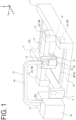
- FIG. 1 is a schematic illustration of an exterior configuration of a laser-beam working machine 1 according to an embodiment of the present invention.
- An X axis illustrated in FIG. 1 extends in a depth direction of the laser-beam working machine 1
- a Y axis extends in a width direction of the laser-beam working machine 1
- a Z axis extends in a height direction of the laser-beam working machine 1.
- directions along the X axis, the Y axis, and the Z axis will be respectively referred to as X direction, Y direction, and Z direction.
- the laser-beam working machine 1 includes a base 10, first guide rails 11, columns 12, a second guide rail 13, a saddle 14, a nozzle 15, a first pump 16, a laser head 20, at least one laser oscillator 30, an optical fiber 40, and a numerical control apparatus 6.
- the laser-beam working machine 1 is an apparatus or a device that machines a metal plate MP on the base 10. Examples of the metal plate MP include soft steel, SUS, aluminum steel, brass, and copper. It is to be noted that the metal plate MP may be referred to as workpiece W.
- the base 10 may include a plurality of elongated projections.
- a pair of first guide rails 11 are mounted on the base 10, one first guide rail 11 being provided at one end of the base 10 in the Y direction and the other first guide rail 11 being provided at another end of the base 10 in the Y direction.
- One of the columns 12 is movably mounted on the one first guide rail 11, and another column 12 is movably mounted on the other first guide rails 11.
- Each column 12 is caused to move on the corresponding first guide rail 11 by, for example, driving force of a driver D1.
- the driver D1 such as a motor, is provided at the first guide rail 11 or the column 12.
- the second guide rail 13 extends along the Y axis, which is orthogonal to the X axis, and is provided across the columns 12.
- the saddle 14 is mounted on second guide rail 13 movably in the Y direction.
- the saddle 14 is caused to move on the second guide rail 13 by, for example, driving force of a driver D2.
- the driver D2 such as a motor, is provided at the second guide rail 13 or the saddle 14.
- Each column 12 may be covered by a bellows cover, which is not illustrated.
- the laser head 20 is mounted on the saddle 14 movably in the Z direction, which extends along the Z axis, which is perpendicular to the X axis and the Y axis.
- the laser head 20 is caused to move on the saddle 14 by, for example, driving force of a driver D3.
- the driver D3, such as a motor, is provided at the saddle 14 or the laser head 20.
- the laser head 20 is configured to machine the metal plate MP on the base 10.
- the laser head 20 includes an optical system to which laser beams sent from the at least one laser oscillator 30 are introduced.
- the laser head 20 includes a torch 28.
- the torch 28 is used for laser machining purposes.
- the nozzle 15 is configured to spray oil to the workpiece W before laser is radiated to the workpiece W by the laser head 20, described later.
- the first pump 16 is configured to send oil to the nozzle 15.
- the oil is stored in an oil tank, not illustrated. While in FIG. 1 the nozzle 15 and the first pump 16 are mounted on the saddle 14, the nozzle 15 and the first pump 16 may be mounted on the base 10.
- the at least one laser oscillator 30 outputs laser beams used to machine the metal plate MP.
- the optical fiber 40 telescopically connects the at least one laser oscillator 30 and the laser head 20 to each other to supply laser beams output from the at least one laser oscillator 30 to the laser head 20.
- the optical fiber 40 includes a first end 40a and a second end 40b.
- the first end 40a receives laser beams from the at least one laser oscillator 30.
- the second end 40b is opposite to the first end 40a.
- the numerical control apparatus 6 includes a control circuit 7.
- the control circuit 7 includes elements such as a hardware processor and a memory.
- the control circuit 7 is configured to control the at least one laser oscillator 30, the drivers M1 to M3, and the first pump 16 to machine the metal plate MP.
- the driver D1 to D3 will be collectively referred to as transfer mechanism TM.
- the transfer mechanism TM is configured to move the torch 28.
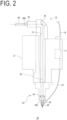
- FIG. 2 is a cross-sectional view of the laser head 20 of the laser-beam working machine 1 according to the embodiment. Specifically, FIG. 2 is a cross-sectional view of the laser head 20 cut along a plane passing through an optical axis RZ of a laser beam radiated from the torch 28.
- the optical system of the laser head 20 will be described.
- the laser head 20 includes a head body 21, an upper unit 22, and a lower unit 23.
- the upper unit 22 is mounted on the head body 21.
- the upper unit 22 includes a connector 25 and a mirror 26.
- the connector 25 is a connector that connects the second end 40b of the optical fiber 40 to the laser head 20. It is to be noted that the mirror 26 reflects the laser beam output from the connector 25 toward the lower unit 23.
- the lower unit 23 is mounted on the head body 21.
- the lower unit 23 includes a lens 24.
- the lens 24 is provided to face the second end 40b of the optical fiber 40, and is configured to focus, toward the workpiece W, the laser beam transmitted through the optical fiber 40. That is, the laser-beam working machine 1 includes the lens 24. It is to be noted that an additional lens may be provided between the connector 25 and the lens 24, which additional lens is not illustrated in FIG. 2 , to focus the laser beam from the second end 40b of the optical fiber 40.
- the torch 28 is mounted on a leading end portion of the lower unit 23. An optical path 27 extends through the upper unit 22, the head body 21, the lower unit 23, and the torch 28 to pass the laser beam through the optical path 27.
- the laser-beam working machine 1 includes a second pump 17 at the head body 21.
- the second pump 17 is configured to send gas to the torch 28.
- the control circuit 7 is configured to control the second pump 17.
- An example of this gas is oxygen gas to promote melting of the workpiece W.
- Other examples include air, nitrogen gas, and argon gas.
- the gas sent from the second pump will be referred to as assist gas AG.
- the assist gas AG is stored in a gas storage 18 (see FIG. 1 ), and is sent to the torch 28 via a gas supply conduit 19.
- the torch 28 includes a connector 29. Via the connector 29, the torch 28 is connected to the gas supply conduit 19.
- the torch 28 includes an opening 28h. The opening 28h is for the laser beam focused by the lens 24 and the gas to be sprayed to the workpiece W to pass.
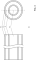
- FIG. 3 is a schematic illustration of an internal configuration of the optical fiber 40 according to the embodiment.
- the optical fiber 40 includes a first transmission portion 42, a second transmission portion 44, a reflector 46, and an additional reflector 48.
- the first transmission portion 42 has a cylindrical shape, and is configured to permit a laser beam to transmit through the first transmission portion 42.
- the reflector 46 is a tubular member that covers the outer circumference of the first transmission portion 42, and is configured to reflect a laser beam at an interface with the first transmission portion 42.
- the second transmission portion 44 is a tubular member that covers the outer circumference of the reflector 46, and is configured to permit a laser beam to transmit through the second transmission portion 44. In other words, the second transmission portion 44 is provided around the first transmission portion 42.
- the reflector 46 is provided between the first transmission portion 42 and the second transmission portion 44.
- the reflector 46 is configured to reflect a laser beam an interface with the second transmission portion 44.
- the additional reflector 48 is a tubular member that covers the outer circumference of the second transmission portion 44, and is configured to reflect a laser beam at an interface with the second transmission portion 44.
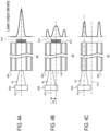
- FIGs. 4A to 4C each are a schematic illustration of an example of output of a laser beam RL according to the embodiment.
- the at least one laser oscillator 30 includes one laser oscillator 30A.
- the laser oscillator 30A emits the laser beam RL.
- the laser oscillator 30A is configured to change a positional relationship between an optical axis Ax1 and a center axis Ax2 in the manners illustrated in FIGs. 4Ato 4C .
- the optical axis Ax1 is an optical axis of the laser beam RL output from the laser oscillator 30A.
- the center axis Ax2 is a center axis of the optical fiber 40.
- FIG. 4A is a schematic illustration of an example in which the optical axis Ax1 of the laser beam RL and the center axis Ax2 of the optical fiber 40 coincide with each other.
- FIG. 4B is a schematic illustration of an example in which the optical axis Ax1 of the laser beam RL extends through a part of the first transmission portion 42 which part is located slightly inward relative to the reflector 46.
- FIG. 4C is a schematic illustration of an example in which the optical axis Ax1 of the laser beam RL extends through a part of the second transmission portion 44 which part is located at or around the center of the second transmission portion 44.
- FIGs. 4A to 4C laser output density level is illustrated.
- a greater laser output density is indicated by the graph line extending further to the right.
- the laser beam RL does not strike the second transmission portion 44. Therefore, the laser output density is at its maximum at and around the center axis Ax2 of the optical fiber 40, and gradually decreases in a direction away from the center axis Ax2.
- FIG. 4B illustrates a case that the optical fiber 40 is sufficiently long.
- the laser output density has two peaks, one at or around the center of the second transmission portion 44 and the other at and around the center axis Ax2 of the optical fiber 40.
- the peak at and around the center axis Ax2 of the optical fiber 40 is larger than the peak at or around the center of the second transmission portion 44.
- substantially no laser beam RL strikes the first transmission portion 42. Therefore, the laser output density has its peak only at or around the center of the second transmission portion 44.
- the peak at or around the center of the second transmission portion 44 is larger than the peak at and around the center axis Ax2 of the optical fiber 40.
- the laser oscillator 30A is positioned as illustrated in FIG. 4B to make the laser output density at the first transmission portion 42 larger than the laser output density at the second transmission portion 44. That is, the direction of the laser beam RL emitted from the one laser oscillator 30A is adjusted so that a part of the laser beam RL enters the first transmission portion 42 and another part of the laser beam RL enters the second transmission portion 44.
- a first laser beam RL1 and a second laser beam RL2 are generated by emitting the laser beam RL from the one laser oscillator 30A in such a manner that a part of the laser beam RL enters the first transmission portion 42 and another part of the laser beam RL enters the second transmission portion 44.
- the laser beam output from the first transmission portion 42 referred to as first laser beam RL1
- the laser beam output from the second transmission portion 44 will be referred to second laser beam RL2.
- the at least one laser oscillator 30 is configured to emit the first laser beam RL1 and the second laser beam RL2.
- the first transmission portion 42 permits the first laser beam RL1 to transmit through the first transmission portion 42.
- the second transmission portion 44 permits the second laser beam RL2 to transmit through the second transmission portion 44.
- FIG. 5 is a schematic illustration of a piercing method according to the embodiment.
- the control circuit 7 is configured to control the first pump 16 to spray oil OIL to the workpiece W to generate a coating portion WCP of oil OIL on the workpiece W.
- the control circuit 7 is configured to control the at least one laser oscillator 30 to radiate the first laser beam RL1 and the second laser beam RL2 to the coating portion WCP.
- the control circuit 7 is configured to control the second pump 17 to spray gas (assist gas AG) to a part MEW of the workpiece W which part MEW has been melted by the first laser beam RL1.
- the control circuit 7 causes a pierced hole PH to be opened in the workpiece W.
- the control circuit 7 is configured to control the second laser beam RL2 to heat a base portion RT of each spatter SPT.
- the spatter SPT is a scatter around the pierced hole PH and generated by the spraying of the gas (assist gas AG) to the melted part MEW of the workpiece W.
- the melted part MEW of the workpiece W is intended to mean a part of the workpiece W which part has been heated to a level of viscosity low enough to be scattered by the assist gas AG.
- the base portion RT is intended to mean a part of the spatter SPT which part contacts, without intervention of the oil OIL, a hole defining part of a machined workpiece MAW.
- the workpiece MAW is a workpiece into which the workpiece W has been machined.
- the hole defining part defines the pierced hole PH.
- FIG. 6 is another schematic illustration of the piercing method according to the embodiment.
- the workpiece W's part MEW which has been melted by the first laser beam RL1
- the control circuit 7 is configured to control the transfer mechanism TM and the second pump 17 to further spray the gas (for example, the assist gas AG) to each spatter SPT.
- the direction of the spraying of the gas to each spatter SPT is different from the direction of the spraying of the gas to the melted part MEW of the workpiece W.
- the control circuit 7 is configured to control the TM and the second pump 17 to spray gas (for example, the assist gas AG) to around the pierced hole PH while moving the torch 28 along a circle CIR.
- gas for example, the assist gas AG
- the circle CIR surrounds the pierced hole PH.
- FIG. 7 is a schematic illustration of a part of the laser beam RL which part is beyond the torch 28 according to the embodiment.
- the laser beam RL is focused most narrowly at a focal point FP, and is slightly widened when striking the surface of the coating portion WCP.
- a part of the coating portion WCP which part is irradiated with the first laser beam RL1 will be referred to as center portion CP, and another part of the coating portion WCP which part is irradiated with the second laser beam RL2 will be referred to as peripheral portion PP.
- the peripheral portion PP surrounds the center portion CP in a radial direction relative to the optical axis RZ of the laser beam RL.
- the boundary between the center portion CP and the peripheral portion PP may be determined based on a position on the workpiece W to which a laser beam imaginarily emitted from the reflectors 46 and 48 of the optical fiber 40 reaches. It is to be noted that as illustrated in FIG. 7 , the assist gas AG is sprayed from the torch 28 to reach both of the center portion CP and the peripheral portion PP.
- the laser output density of the first laser beam RL1 in the center portion CP will be referred to as first laser output density
- the laser output density of the second laser beam RL2 in the peripheral portion PP will be referred to second laser output density.
- the first laser output density is larger than the second laser output density.
- the laser output density at a boundary portion BP (where the principle described by referring to FIG. 4B applies) of the coating portion WCP between the center portion CP and the peripheral portion PP will be referred to third laser output density.
- the third laser output density is smaller than the first laser output density and the second laser output density.
- each of the first to third laser output densities varies between the top portion WTP of the workpiece W and the bottom portion WBP of the workpiece W.
- the diameter of the center portion CP at the top portion WTP of the workpiece W is smaller than the diameter of the center portion CP at the bottom portion WBP of the workpiece W.
- the diameter, DBT, of the peripheral portion PP at the top portion WTP of the workpiece W is smaller than the diameter, DBB, of the peripheral portion PP at the bottom portion WBP of the workpiece W.
- the first to third laser output densities at the top portion WTP of the workpiece W are respectively larger than the first to third laser output densities at the bottom portion WBP of the workpiece W.
- the laser output density at each of the center portion CP, the peripheral portion PP, and the boundary portion BP on the same plane varies throughout each portion.
- each of the first to third laser output densities is an average of laser output densities throughout each of the center portion CP, the peripheral portion PP, and the boundary portion BP, which are determined based on an imaginary optical path between the reflectors 46 and 48.
- the first to third laser output densities are determined based on a cross-section of the workpiece W cut along a center plane CTP between the top portion WTP and the bottom portion WBP of the workpiece W.
- the first laser output density is an average of laser output densities throughout the cross-section of the center portion CP
- the second laser output density is an average of laser output densities throughout the cross-section of the peripheral portion PP
- the third laser output density is an average of laser output densities throughout the cross-section of the boundary portion BP.
- the center portion CP may be regarded as a solid-cylindrical shape whose diameter is equivalent to the diameter, DCC, of the cross-section at the center plane CTP; and the peripheral portion PP may be regarded as a tubular shape whose outer diameter and inner diameter are respectively equivalent to the outer diameter DBC and the inner diameter DCC of the cross-section at the center plane CTP.
- the first laser output density and the second laser output density are determined based on the output of the at least one laser oscillator 30 (the laser oscillator 30A), the shift, DX (see FIG. 4B ), between the optical axis Ax1 of the laser beam RL and the center axis Ax2 of the optical fiber 40, and the distance, LW, between the focal point FP and the coating portion WCP.
- the control circuit 7 is capable of controlling the at least one laser oscillator 30 and the position of the torch 28 to adjust these values.
- the first laser output density and the second laser output density satisfy the following conditions.
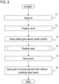
- FIG. 9 is a flowchart of the laser piercing method according to the embodiment.
- the method includes spraying the oil OIL to the workpiece W to generate the coating portion WCP, is a cover of the oil OIL over the workpiece W.
- the method includes positioning the torch 28 relative to the workpiece W to align the center portion CP with a target position on the workpiece W.
- the method includes: setting the laser output density of the laser beam RL to the first laser output density at the coating portion WCP's center portion CP, which is irradiated with the laser beam RL; setting the laser output density of the laser beam RL to the second laser output density, which is smaller than the first laser output density, at the coating portion WCP's peripheral portion PP, which surrounds the center portion CP; and setting the laser output density of the laser beam RL to the third laser output density, which is smaller than the first laser output density and the second laser output density, at the coating portion WCP's boundary portion BP, which is between the center portion CP and the peripheral portion PP.
- the method includes spraying, from the torch 28, the assist gas AG toward the positioned center portion CP of the workpiece W.
- the method includes adjusting the output of the laser oscillator 30A and the shift DX between the optical axis Ax1 of the laser beam RL and the center axis Ax2 of the optical fiber 40, and radiates the laser beam RL toward the coating portion WCP.
- the first laser beam RL1 which is radiated to the center portion CP, melts a part of the workpiece W, which is provided under the coating portion WCP, and gas (assist gas AG) is sprayed to the melted part MEW of the workpiece W to scatter the melted part MEW of the workpiece W to around the center portion CP.
- gas assistant gas AG
- the method includes causing the first laser beam RL1 to melt a part of the workpiece W, which is provided under the coating portion WCP, to a degree that the outer side portion surrounding the peripheral portion PP is not pierced through.
- the method also includes causing the second laser beam RL2, which is radiated to the peripheral portion PP, to heat the base portion RT of the spatter SPT.
- the base portion RT is the scattered part of the workpiece W and contacts, without intervention of the oil OII,, the hole defining part of the machined workpiece MAW which hole defining part defines the pierced hole PH.
- the method includes causing the second laser beam RL2 to heat the spatter SPT to a degree that prevents the spatter SPT from adhering to the machined workpiece MAW and from solidifying on the machined workpiece MAW.
- the method further includes causing the second laser beam RL2 to heat the workpiece W to a degree that the outer side portion surrounding the peripheral portion PP is not pierced through.
- the method includes causing the second laser beam RL2 to heat the workpiece W to a degree that a spatter SPT does not occur at the outer side portion surrounding the peripheral portion PP.
- the method includes, after heating the base portion RT of the spatter SPT, moving the torch 28 that is spraying gas (assist gas AG) along a circle surrounding the base portion RT from outside the base portion RT.
- the method may include a motion of raising and lowering the torch 28 to float the spatter SPT.
- the method includes, without radiating the laser beam RL, spraying gas (assist gas AG) from the torch 28 to around the base portion RT.
- this method which includes spraying gas (assist gas AG) to the spatter SPT, the spatter SPT is removed from the machined workpiece MAW.
- the metal plate MP used in the experiment is a SS400 steel having a plate thickness of 9.0 mm.
- the position of the torch 28 is adjusted such that the top portion WTP of the workpiece W is positioned at a height of 8.5 mm from the focal point.
- the first laser beam RL1 passes through a region R1.
- the region R1 has a diameter DC (see FIG. 7 ) of 0.234 mm.
- the second laser beam RL2 passes through a region R2.
- the region R2 has a diameter DP (see FIG. 7 ) of 0.806 mm.
- the center plane CTP of the workpiece W, the center portion CP has a diameter DCC of 1.066 mm.
- the peripheral portion PP has a diameter DBC of 1.492 mm.
- the optical axis Ax1 of the laser beam RL is positioned in the manner illustrated in FIG. 8A .
- the laser oscillator 30A opens a punched hole in the metal plate MP by heating the metal plate MP for 0.1 seconds at 1000W and a duty ratio of 15%.
- the shift DXbetween the optical axis Ax1 and the center axis Ax2 was changed, and the laser oscillator 30A was caused to output the laser beam RL at 9000W and a duty ratio of 25%.
- the air pressure of the assist gas sprayed at step S3 is 0.4 MPa.
- FIG. 10 illustrates the diameters of the pierced holes and images of piercing marks.
- the images of piercing marks and the diameters of the pierced holes illustrated in FIG. 10 are equivalent to results of the processings up to step S4.
- the generated pierced hole has a hole diameter of greater than 1.1 mm. Therefore, samples 1 to 9 satisfy [Condition 1].
- the generated pierced hole has a hole diameter of greater than 1.4 mm.
- the second laser output density is substantially small. Therefore, sample 0 do not satisfy [Condition 4].
- samples 1 to 3 As the sample number increases, the number of spatters SPT increases whose base portions RT are heated ideally, and the number of such spatters SPT decreases by being removed by the assist gas sprayed at step S3.
- Samples 1 to 3 satisfy [Condition 1] through [Condition 5]. As the sample number increases, [Condition 4] is satisfied more ideally. Sample 3 satisfies [Condition 4] more ideally. In this case, the strength of the base portion of the spatter SPT can be degraded enough to enable the spatter SPT to be removed only by the air pressure of the assist gas sprayed at step S3.
- Whether [Condition 4] is satisfied can be judged by comparing the amount of spatter with the amount of spatter in a case that the second laser output density is substantially 0 to determine whether the amount of spatter is decreased.
- the case that the second laser output density is substantially 0 is intended to mean a case that the optical axis Ax 1 of the laser beam RL output from the laser oscillator 30A is set to align with the center axis Ax2 of the optical fiber 40, and the laser beam RL is output.
- the at least one laser oscillator 30 is made up of two laser oscillators, one laser oscillator being configured to output the first laser beam RL1 and the other laser oscillator being configured to output the second laser beam RL2, the case that the second laser output density is substantially 0 is intended to mean a case that the output of the laser oscillator configured to output the second laser beam RL2 is set to 0 without changing the output of the laser oscillator configured to output the first laser beam RL1.
- Whether [Condition 5] is satisfied can be judged by: increasing the second laser output density stepwise; and determining whether the amount of spatter has increased as compared with the amount of spatter in the immediately previous step, even though the diameter of the pierced hole remains unchanged.
- the base portion RT of the spatter SPT is heated by the second laser beam RL2, which is radiated to the peripheral portion PP.
- the spatter SPT is equivalent to the scattered part of the workpiece W and contacts, without intervention of the oil OIL, the hole defining part of the machined workpiece MAW which hole defining part defines the pierced hole PH.
- the at least one laser oscillator 30 includes one laser oscillator 30A, which emits a laser beam.
- the laser beam may include a first laser beam emitted from one laser oscillator and a second laser beam emitted from a different laser oscillator.
- the manner of moving the torch 28 at step S5 will not be limited to along the circle CIR; the manner of moving may be along an ellipse or may be such that the torch 28 is moved toward or away from the workpiece W during rotation.
- the laser-beam working machine 1 is described as machining the metal plate MP.
- the embodiment is also applicable to a laser-beam working machine that machines any other material such as a pipe.
- the laser head 20 may be rotatable about rotation axes respectively parallel to the X axis and the Y axis in order to be capable of three-dimensional machining.
- a component suffixed with a term such as "member”, “portion”, “part”, “element”, “body”, and “structure” is intended to mean that there is a single such component or a plurality of such components.
- ordinal terms such as “first” and “second” are merely used for distinguishing purposes and there is no other intention (such as to connote a particular order) in using ordinal terms.
- first element does not connote the existence of “second element”; otherwise, the mere use of “second element” does not connote the existence of "first element”.
- approximating language such as “approximately”, “about”, and “substantially” may be applied to modify any quantitative representation that could permissibly vary without a significant change in the final result obtained. All of the quantitative representations recited in the present application shall be construed to be modified by approximating language such as “approximately”, “about”, and “substantially”.
Landscapes
- Engineering & Computer Science (AREA)
- Physics & Mathematics (AREA)
- Optics & Photonics (AREA)
- Plasma & Fusion (AREA)
- Mechanical Engineering (AREA)
- Laser Beam Processing (AREA)
- Light Guides In General And Applications Therefor (AREA)
Abstract
Description
- The present invention relates to a laser piercing method and a laser-beam working machine.
- Many laser-beam working machines use a single laser source (for example, Patent Literature 1).
Patent Literature 2 recites a machine tool that controls the strength of laser at a center portion and a peripheral portion of a laser spot to minimize adherence of spatter to a workpiece with its thickness taken into consideration, in an attempt to provide high-quality piercing.Patent Literature 3 discloses a technique to prevent piercing-caused adherence of spatter by applying oil before piercing. -
- PTL1:
JP H8-192283 A - PTL2:
WO/2017/134964 . - PTL3:
JP 2000-84686 A - Even if oil is applied before piercing, a base portion of spatter adjacent to a pierced hole is directly connected to the material of the workpiece, without oil intervention. If the base portion is cooled and solidified in the process of piercing, it is difficult to remove spatter.
- An object of the technique disclosed in the present application is to provide a laser piercing method and a laser-beam working machine that improve machining quality by preventing a base portion of a piercing-caused spatter from solidifying.
- A laser piercing method according to a first embodiment of the present disclosure includes spraying oil to a workpiece to generate a coating portion made of the oil over the workpiece. The method includes radiating a laser beam to the coating portion to: set a laser output density of the laser beam to a first laser output density at a center portion of the coating portion which center portion is irradiated with the laser beam; set the laser output density to a second laser output density at a peripheral portion of the coating portion which peripheral portion surrounds the center portion, the second laser output density being smaller than the first laser output density; and set the laser output density to a third laser output density at a boundary portion of the coating portion which boundary portion is between the center portion and the peripheral portion, the third laser output density being smaller than the second laser output density. The method includes opening a pierced hole through the coating portion by: melting a part of the workpiece which part is under the coating portion by a first laser beam, among the laser beam, that is radiated to the center portion; and spraying gas to the melted part of the workpiece to scatter the melted part of the workpiece to around the center portion. The method includes heating a base portion of a spatter by a second laser beam, among the laser beam, that is radiated to the peripheral portion. The spatter is made of the scattered part of the workpiece and contacts, without intervention of the oil, a hole defining part of the workpiece that has been machined which hole defining part defines the pierced hole.
- According to a second embodiment of the present disclosure, the laser piercing method according to the first embodiment includes, after heating the base portion, spraying the gas to the spatter to remove the spatter from the machined workpiece. It is to be noted that the direction in which gas is sprayed to the spatter is preferably different from the direction in which gas is sprayed to scatter the melted part of the workpiece.
- According to a third embodiment of the present disclosure, in the laser piercing method according to the second embodiment, removing the spatter from the machined workpiece includes spraying the gas to around the base portion through a torch while moving the torch along a circle surrounding the base portion from outside the base portion.
- According to a fourth embodiment of the present disclosure, in the laser piercing method according to any one of the first to third embodiments, the spatter is heated by the second laser beam to a degree that prevents the spatter from adhering to the machined workpiece and from solidifying on the machined workpiece. In a case that a plurality of spatters occur by the first laser beam, the plurality of spatters may be heated by the second laser beam to a degree that prevents at least one spatter of the plurality of spatters from adhering to the machined workpiece and from solidifying on the machined workpiece. In this case, the plurality of spatters are preferably heated by the second laser beam to a degree that causes at least one spatter of the plurality of spatters to be scattered by the gas according to the second or third embodiment. Also, the plurality of spatters are further preferably heated by the second laser beam to a degree that causes all the spatters of the plurality of spatters to be scattered by the gas according to the second or third embodiment. The plurality of spatters are further preferably heated by the second laser beam to a degree that prevents all the spatters of the plurality of spatters from adhering to the machined workpiece and from solidifying on the machined workpiece.
- According to a fifth embodiment of the present disclosure, in the laser piercing method according to any one of the first to fourth embodiments, the workpiece is heated by the second laser beam to a degree that prevents an outer side portion surrounding the peripheral portion from being pierced through.
- According to a sixth embodiment of the present disclosure, in the laser piercing method according to the fifth embodiment, the part of the workpiece under the coating portion is melted by the first laser beam to a degree that prevents the outer side portion surrounding the peripheral portion from being pierced through.
- According to a seventh embodiment of the present disclosure, in the laser piercing method according to the fifth embodiment or the sixth embodiment, the workpiece is heated by the second laser beam to a degree that prevents a spatter from occurring at the outer side portion surrounding the peripheral portion.
- According to an eighth embodiment of the present disclosure, the laser piercing method according to any one of the first to seventh embodiments further includes preparing an optical fiber that includes a first transmission portion, a second transmission portion provided around the first transmission portion, and a reflector provided between the first transmission portion and the second transmission portion. The method further includes generating the first laser beam and the second laser beam by emitting the laser beam from one laser oscillator such that a part of the laser beam enters the first transmission portion and another part of the laser beam enters the second transmission portion.
- A laser-beam working machine according to a ninth embodiment of the present disclosure includes at least one laser oscillator, an optical fiber, a lens, a torch, a transfer mechanism, a nozzle, a first pump, a second pump, and a control circuit. The at least one laser oscillator is configured to emit a first laser beam and a second laser beam. The optical fiber has a first end at which the first laser beam and the second laser beam are received from the at least one laser oscillator and having a second end opposite to the first end. The optical fiber includes a first transmission portion through which the first laser beam is passed, a second transmission portion which is provided around the first transmission portion and through which the second laser beam is passed, and a reflector provided between the first transmission portion and the second transmission portion. The lens is provided to face the second end of the optical fiber and configured to focus the first laser beam and the second laser beam toward a workpiece after the first laser beam and the second laser beam have been transmitted through the optical fiber. The torch has an opening through which the beams focused by the lens and gas to be sprayed to the workpiece are passed. The transfer mechanism is configured to move the torch. The nozzle is configured to spray oil to the workpiece. The first pump is configured to send the oil to the nozzle. The second pump is configured to send the gas to the torch. The control circuit is configured to control the at least one laser oscillator, the first pump, the second pump, and the transfer mechanism. The control circuit is configured to control the first pump to spray the oil to the workpiece to generate a coating portion made of the oil over the workpiece. Then, the control circuit is configured to control the at least one laser oscillator and the second pump to radiate the first laser beam and the second laser beam to the coating portion and spray the gas to the workpiece melted by the first laser beam to open a pierced hole through the coating portion. A laser output density at a center portion of the coating portion which center portion is irradiated with the first laser beam is set to a first laser output density, a laser output density at a peripheral portion of the coating portion which peripheral portion is irradiated with the second laser beam is set to a second laser output density that is smaller than the first laser output density, and a laser output density at a boundary portion of the coating portion which boundary portion is between the center portion and the peripheral portion is set to a third laser output density that is smaller than the second laser output density.
- According to a tenth embodiment of the present disclosure, in the laser-beam working machine according to the ninth embodiment, the control circuit is configured to control the transfer mechanism and the second pump to spray the gas to a spatter made of the workpiece melted by the first laser beam and scattered to around the pierced hole by the gas. It is to be noted that the direction in which gas is sprayed to the spatter is preferably different from the direction in which the gas is sprayed to scatter the melted part of the workpiece.
- According to an eleventh embodiment of the present disclosure, in the laser-beam working machine according to the tenth embodiment, the control circuit is configured to control the transfer mechanism and the second pump to spray the gas to around the pierced hole while moving the torch along a circle surrounding the pierced hole.
- According to a twelfth embodiment of the present disclosure, in the laser-beam working machine according to any one of the ninth to eleventh embodiments, the second laser output density is such a degree of laser output density that causes the second laser beam to heat the workpiece to such a degree that a spatter made of the workpiece melted by the first laser beam and scattered to around the pierced hole by the gas is prevented from adhering to and solidifying on a hole defining part of the workpiece that has been machined which hole defining part defines the pierced hole. In a case that a plurality of spatters occur by the first laser beam, the laser output density may have such a degree that causes the second laser beam to heat the workpiece to a degree that prevents at least one spatter of the plurality of spatters from adhering to the machined workpiece and from solidifying on the machined workpiece. In this case, the laser output density may preferably have such a degree that causes the second laser beam to heat the workpiece to a degree that causes at least one spatter of the plurality of spatters to be scattered by the gas according to the second or third embodiment. Also, the laser output density may further preferably have such a degree that causes the second laser beam to heat the workpiece to a degree that causes all the spatters of the plurality of spatters to be scattered by the gas according to the second or third embodiment. The laser output density may further preferably have such a degree that causes the second laser beam to heat the workpiece to a degree that prevents all the spatters of the plurality of spatters from adhering to the machined workpiece and from solidifying on the machined workpiece.
- According to a thirteenth embodiment of the present disclosure, in the laser-beam working machine according to any one of the ninth to twelfth embodiments, the first laser output density is such a degree of laser output density that causes the first laser beam to heat the workpiece to a degree that prevents an outer side portion surrounding the peripheral portion from being pierced through, and the second laser output density is such a degree of laser output density that causes the second laser beam to heat the workpiece to a degree that prevents the outer side portion surrounding the peripheral portion from being pierced through.
- According to a fourteenth embodiment of the present disclosure, in the laser-beam working machine according to the thirteenth embodiment, the second laser output density is such a degree of laser output density that causes the second laser beam to heat the workpiece to a degree that prevents a spatter from occurring at the outer side portion surrounding the peripheral portion.
- According to a fifteenth embodiment of the present disclosure, in the laser-beam working machine according to any one of the ninth to fourteenth embodiments, the at least one laser oscillator includes one laser oscillator configured to emit a laser beam. In the laser-beam working machine, a direction of the laser beam of the one laser oscillator is adjusted so that a part of the laser beam enters the first transmission portion and another part of the laser beam enters the second transmission portion.
- In the laser piercing method according to the first embodiment, the base portion of the spatter is heated by the second laser beam. The second laser beam has a second laser output density lower than the output density of the first laser beam, by which the pierced hole has been opened. This prevents the base portion of the spatter from adhering to the part of the workpiece defining the periphery of the pierced hole, and thus makes the spatter easily removable. The laser-beam working machine according to the ninth embodiment is capable of heating the base portion of the spatter by the second laser beam, which has the second laser output density.
- In the laser piercing method according to the second embodiment and the laser-beam working machine according to the tenth embodiment, a spatter is easily removable by gas since its base portion is heated to be kept from adhering to the workpiece.
- In the laser piercing method according to the third embodiment and the laser-beam working machine according to the eleventh embodiment, gas is sprayed from outside the spatter toward its base portion. This ensures that more spatters can be removed by gas.
- In the laser piercing method according to the fourth embodiment and the laser-beam working machine according to the twelfth embodiment, a spatter is easily removable by gas since the base portion of the spatter is not adhered to the workpiece and not solidified on the workpiece.
- If a portion of the workpiece located outside its heated region where the second laser beam is directed is pierced through, a base portion of a spatter resulting from the heating can not be heated directly by the second laser beam. As a result, the base portion is cooled and adheres to the workpiece. In the laser piercing method according to the fifth embodiment, the workpiece is heated by the second laser beam to a degree that the outside portion of the heated region is not pierced through. This configuration reduces the above-described adhesion risk. A similar adhesion problem occurs if the second laser beam is weak or if the heated region is small as compared with a pierced region, in which case the outside portion of the heated region may be pierced through by the first laser beam. In the laser piercing method according to the sixth embodiment, the workpiece is heated by the first laser beam to a degree that the outside portion of the heated region is not pierced through. This configuration further reduces the above-described adhesion risk. In the laser-beam working machine according to the thirteenth embodiment, the workpiece is heated by the first laser beam and the second laser beam to a degree that the outside portion of the heated region is not pierced through. This configuration reduces the above-described risk.
- Even if the outside portion of the heated region is not pierced through, there may be a case that the second laser beam melts a part of a peripheral portion of a pierced hole outside the region where the second laser beam is directed. If the melted part is scattered by assist gas, turning into a spatter, the base portion of the spatter can not be heated directly by the second laser beam. As a result, the base portion is cooled and adheres to the workpiece. In the laser piercing method according to the seventh embodiment and the laser-beam working machine according to the fourteenth embodiment, the workpiece is heated by the second laser beam to a degree that prevents a spatter from occurring at the outside of the machining region. This configuration reduces the above-described adhesion risk.
- In the laser piercing method according to the eighth embodiment and the laser-beam working machine according to the fifteenth embodiment, the first laser beam and the second laser beam are generated by one laser oscillator. This configuration reduces the cost of production.
- The technique disclosed in the present application provides a laser piercing method and a laser-beam working machine that improve machining quality by preventing a base portion of a piercing-caused spatter from solidifying.
-
- [
FIG. 1] FIG. 1 is a schematic illustration of an exterior configuration of a laser-beam working machine according to an embodiment. - [
FIG. 2] FIG. 2 is a cross-sectional view of a laser head of the laser-beam working machine according to the embodiment. - [
FIG. 3] FIG. 3 is a schematic illustration of an internal configuration of an optical fiber according to the embodiment. - [
FIG. 4A] FIG. 4A is a schematic illustration of an example of a laser beam output according to the embodiment. - [
FIG. 4B] FIG. 4B is a schematic illustration of an example of a laser beam output according to the embodiment. - [
FIG. 4C] FIG. 4C is a schematic illustration of an example of a laser beam output according to the embodiment. - [
FIG. 5] FIG. 5 is a schematic illustration of a piercing method according to the embodiment. - [
FIG. 6] FIG. 6 is another schematic illustration of the piercing method according to the embodiment. - [
FIG. 7] FIG. 7 is a schematic illustration of a part of a laser beam which part is beyond a torch according to the embodiment. - [
FIG. 8A] FIG. 8A is a schematic illustration of an example of an undesirable piercing method according to the embodiment. - [
FIG. 8B] FIG. 8B is a schematic illustration of an example of an undesirable piercing method according to the embodiment. - [
FIG. 9] FIG. 9 is a flowchart of the piercing method according to the embodiment. - [
FIG. 10] FIG. 10 shows results of a verification experiment. - The present invention will now be described with reference to the accompanying drawings, wherein like reference numerals designate corresponding or identical elements throughout the various drawings.
-
FIG. 1 is a schematic illustration of an exterior configuration of a laser-beam working machine 1 according to an embodiment of the present invention. An X axis illustrated inFIG. 1 extends in a depth direction of the laser-beam working machine 1, a Y axis extends in a width direction of the laser-beam working machine 1, and a Z axis extends in a height direction of the laser-beam working machine 1. In the following description, directions along the X axis, the Y axis, and the Z axis will be respectively referred to as X direction, Y direction, and Z direction. As illustrated inFIG. 1 , the laser-beam working machine 1 includes abase 10,first guide rails 11,columns 12, asecond guide rail 13, asaddle 14, anozzle 15, afirst pump 16, alaser head 20, at least onelaser oscillator 30, anoptical fiber 40, and anumerical control apparatus 6. The laser-beam working machine 1 is an apparatus or a device that machines a metal plate MP on thebase 10. Examples of the metal plate MP include soft steel, SUS, aluminum steel, brass, and copper. It is to be noted that the metal plate MP may be referred to as workpiece W. The base 10 may include a plurality of elongated projections. A pair offirst guide rails 11 are mounted on thebase 10, onefirst guide rail 11 being provided at one end of the base 10 in the Y direction and the otherfirst guide rail 11 being provided at another end of the base 10 in the Y direction. One of thecolumns 12 is movably mounted on the onefirst guide rail 11, and anothercolumn 12 is movably mounted on the other first guide rails 11. Eachcolumn 12 is caused to move on the correspondingfirst guide rail 11 by, for example, driving force of a driver D1. The driver D1, such as a motor, is provided at thefirst guide rail 11 or thecolumn 12. - The
second guide rail 13 extends along the Y axis, which is orthogonal to the X axis, and is provided across thecolumns 12. Thesaddle 14 is mounted onsecond guide rail 13 movably in the Y direction. Thesaddle 14 is caused to move on thesecond guide rail 13 by, for example, driving force of a driver D2. The driver D2, such as a motor, is provided at thesecond guide rail 13 or thesaddle 14. Eachcolumn 12 may be covered by a bellows cover, which is not illustrated. Thelaser head 20 is mounted on thesaddle 14 movably in the Z direction, which extends along the Z axis, which is perpendicular to the X axis and the Y axis. Thelaser head 20 is caused to move on thesaddle 14 by, for example, driving force of a driver D3. The driver D3, such as a motor, is provided at thesaddle 14 or thelaser head 20. Thelaser head 20 is configured to machine the metal plate MP on thebase 10. Thelaser head 20 includes an optical system to which laser beams sent from the at least onelaser oscillator 30 are introduced. Thelaser head 20 includes atorch 28. Thetorch 28 is used for laser machining purposes. - The
nozzle 15 is configured to spray oil to the workpiece W before laser is radiated to the workpiece W by thelaser head 20, described later. Thefirst pump 16 is configured to send oil to thenozzle 15. The oil is stored in an oil tank, not illustrated. While inFIG. 1 thenozzle 15 and thefirst pump 16 are mounted on thesaddle 14, thenozzle 15 and thefirst pump 16 may be mounted on thebase 10. The at least onelaser oscillator 30 outputs laser beams used to machine the metal plate MP. Theoptical fiber 40 telescopically connects the at least onelaser oscillator 30 and thelaser head 20 to each other to supply laser beams output from the at least onelaser oscillator 30 to thelaser head 20. Theoptical fiber 40 includes afirst end 40a and asecond end 40b. Thefirst end 40a receives laser beams from the at least onelaser oscillator 30. Thesecond end 40b is opposite to thefirst end 40a. Thenumerical control apparatus 6 includes acontrol circuit 7. Thecontrol circuit 7 includes elements such as a hardware processor and a memory. Thecontrol circuit 7 is configured to control the at least onelaser oscillator 30, the drivers M1 to M3, and thefirst pump 16 to machine the metal plate MP. In the following description of the embodiment, the driver D1 to D3 will be collectively referred to as transfer mechanism TM. The transfer mechanism TM is configured to move thetorch 28. -
FIG. 2 is a cross-sectional view of thelaser head 20 of the laser-beam working machine 1 according to the embodiment. Specifically,FIG. 2 is a cross-sectional view of thelaser head 20 cut along a plane passing through an optical axis RZ of a laser beam radiated from thetorch 28. By referring toFIG. 2 , the optical system of thelaser head 20 will be described. As illustrated inFIG. 2 , thelaser head 20 includes ahead body 21, anupper unit 22, and alower unit 23. Theupper unit 22 is mounted on thehead body 21. Theupper unit 22 includes aconnector 25 and amirror 26. Theconnector 25 is a connector that connects thesecond end 40b of theoptical fiber 40 to thelaser head 20. It is to be noted that themirror 26 reflects the laser beam output from theconnector 25 toward thelower unit 23. - The
lower unit 23 is mounted on thehead body 21. Thelower unit 23 includes alens 24. Thelens 24 is provided to face thesecond end 40b of theoptical fiber 40, and is configured to focus, toward the workpiece W, the laser beam transmitted through theoptical fiber 40. That is, the laser-beam working machine 1 includes thelens 24. It is to be noted that an additional lens may be provided between theconnector 25 and thelens 24, which additional lens is not illustrated inFIG. 2 , to focus the laser beam from thesecond end 40b of theoptical fiber 40. Thetorch 28 is mounted on a leading end portion of thelower unit 23. Anoptical path 27 extends through theupper unit 22, thehead body 21, thelower unit 23, and thetorch 28 to pass the laser beam through theoptical path 27. - As illustrated in
FIG. 2 , the laser-beam working machine 1 includes asecond pump 17 at thehead body 21. Thesecond pump 17 is configured to send gas to thetorch 28. Thecontrol circuit 7 is configured to control thesecond pump 17. An example of this gas is oxygen gas to promote melting of the workpiece W. Other examples include air, nitrogen gas, and argon gas. In the following description of the embodiment, the gas sent from the second pump will be referred to as assist gas AG. The assist gas AG is stored in a gas storage 18 (seeFIG. 1 ), and is sent to thetorch 28 via agas supply conduit 19. Thetorch 28 includes aconnector 29. Via theconnector 29, thetorch 28 is connected to thegas supply conduit 19. Thetorch 28 includes anopening 28h. Theopening 28h is for the laser beam focused by thelens 24 and the gas to be sprayed to the workpiece W to pass. -
FIG. 3 is a schematic illustration of an internal configuration of theoptical fiber 40 according to the embodiment. Theoptical fiber 40 includes afirst transmission portion 42, asecond transmission portion 44, areflector 46, and anadditional reflector 48. Thefirst transmission portion 42 has a cylindrical shape, and is configured to permit a laser beam to transmit through thefirst transmission portion 42. Thereflector 46 is a tubular member that covers the outer circumference of thefirst transmission portion 42, and is configured to reflect a laser beam at an interface with thefirst transmission portion 42. Thesecond transmission portion 44 is a tubular member that covers the outer circumference of thereflector 46, and is configured to permit a laser beam to transmit through thesecond transmission portion 44. In other words, thesecond transmission portion 44 is provided around thefirst transmission portion 42. Thereflector 46 is provided between thefirst transmission portion 42 and thesecond transmission portion 44. Thereflector 46 is configured to reflect a laser beam an interface with thesecond transmission portion 44. Theadditional reflector 48 is a tubular member that covers the outer circumference of thesecond transmission portion 44, and is configured to reflect a laser beam at an interface with thesecond transmission portion 44. -
FIGs. 4A to 4C each are a schematic illustration of an example of output of a laser beam RL according to the embodiment. In this embodiment, the at least onelaser oscillator 30 includes onelaser oscillator 30A. Thelaser oscillator 30A emits the laser beam RL. Thelaser oscillator 30A is configured to change a positional relationship between an optical axis Ax1 and a center axis Ax2 in the manners illustrated inFIGs. 4Ato 4C . The optical axis Ax1 is an optical axis of the laser beam RL output from thelaser oscillator 30A. The center axis Ax2 is a center axis of theoptical fiber 40.FIG. 4A is a schematic illustration of an example in which the optical axis Ax1 of the laser beam RL and the center axis Ax2 of theoptical fiber 40 coincide with each other.FIG. 4B is a schematic illustration of an example in which the optical axis Ax1 of the laser beam RL extends through a part of thefirst transmission portion 42 which part is located slightly inward relative to thereflector 46.FIG. 4C is a schematic illustration of an example in which the optical axis Ax1 of the laser beam RL extends through a part of thesecond transmission portion 44 which part is located at or around the center of thesecond transmission portion 44. - On the right side of the figure of the
optical fiber 40 inFIGs. 4A to 4C , laser output density level is illustrated. InFIGs. 4A to 4C , a greater laser output density is indicated by the graph line extending further to the right. InFIG. 4A , the laser beam RL does not strike thesecond transmission portion 44. Therefore, the laser output density is at its maximum at and around the center axis Ax2 of theoptical fiber 40, and gradually decreases in a direction away from the center axis Ax2.FIG. 4B , illustrates a case that theoptical fiber 40 is sufficiently long. In this case, due to the influence of irregular reflection at thereflector 46 and theadditional reflector 48, the laser output density has two peaks, one at or around the center of thesecond transmission portion 44 and the other at and around the center axis Ax2 of theoptical fiber 40. Specifically, the peak at and around the center axis Ax2 of theoptical fiber 40 is larger than the peak at or around the center of thesecond transmission portion 44. InFIG. 4C , substantially no laser beam RL strikes thefirst transmission portion 42. Therefore, the laser output density has its peak only at or around the center of thesecond transmission portion 44. Alternatively, the peak at or around the center of thesecond transmission portion 44 is larger than the peak at and around the center axis Ax2 of theoptical fiber 40. - In this embodiment, the
laser oscillator 30A is positioned as illustrated inFIG. 4B to make the laser output density at thefirst transmission portion 42 larger than the laser output density at thesecond transmission portion 44. That is, the direction of the laser beam RL emitted from the onelaser oscillator 30A is adjusted so that a part of the laser beam RL enters thefirst transmission portion 42 and another part of the laser beam RL enters thesecond transmission portion 44. In other words, a first laser beam RL1 and a second laser beam RL2 are generated by emitting the laser beam RL from the onelaser oscillator 30A in such a manner that a part of the laser beam RL enters thefirst transmission portion 42 and another part of the laser beam RL enters thesecond transmission portion 44. In the following description of the embodiment, the laser beam output from thefirst transmission portion 42 referred to as first laser beam RL1, and the laser beam output from thesecond transmission portion 44 will be referred to second laser beam RL2. Thus, the at least onelaser oscillator 30 is configured to emit the first laser beam RL1 and the second laser beam RL2. Thefirst transmission portion 42 permits the first laser beam RL1 to transmit through thefirst transmission portion 42. Thesecond transmission portion 44 permits the second laser beam RL2 to transmit through thesecond transmission portion 44. -
FIG. 5 is a schematic illustration of a piercing method according to the embodiment. In this embodiment, as illustrated inFIG. 5 , thecontrol circuit 7 is configured to control thefirst pump 16 to spray oil OIL to the workpiece W to generate a coating portion WCP of oil OIL on the workpiece W. Then, thecontrol circuit 7 is configured to control the at least onelaser oscillator 30 to radiate the first laser beam RL1 and the second laser beam RL2 to the coating portion WCP. At the same time, thecontrol circuit 7 is configured to control thesecond pump 17 to spray gas (assist gas AG) to a part MEW of the workpiece W which part MEW has been melted by the first laser beam RL1. Thus, thecontrol circuit 7 causes a pierced hole PH to be opened in the workpiece W. In particular, thecontrol circuit 7 is configured to control the second laser beam RL2 to heat a base portion RT of each spatter SPT. The spatter SPT is a scatter around the pierced hole PH and generated by the spraying of the gas (assist gas AG) to the melted part MEW of the workpiece W. The melted part MEW of the workpiece W is intended to mean a part of the workpiece W which part has been heated to a level of viscosity low enough to be scattered by the assist gas AG. The base portion RT is intended to mean a part of the spatter SPT which part contacts, without intervention of the oil OIL, a hole defining part of a machined workpiece MAW. The workpiece MAW is a workpiece into which the workpiece W has been machined. The hole defining part defines the pierced hole PH. -
FIG. 6 is another schematic illustration of the piercing method according to the embodiment. In this embodiment, the workpiece W's part MEW, which has been melted by the first laser beam RL1, is scattered to around the pierced hole PH by gas (for example, the assist gas AG) to become spatters SPT as illustrated inFIG. 6 . Thecontrol circuit 7 is configured to control the transfer mechanism TM and thesecond pump 17 to further spray the gas (for example, the assist gas AG) to each spatter SPT. It is to be noted that the direction of the spraying of the gas to each spatter SPT is different from the direction of the spraying of the gas to the melted part MEW of the workpiece W. It is also to be noted that the gas sprayed to each spatter SPT may be different from the gas used to scatter the melted part of the workpiece. Specifically, as illustrated inFIG. 6 , thecontrol circuit 7 is configured to control the TM and thesecond pump 17 to spray gas (for example, the assist gas AG) to around the pierced hole PH while moving thetorch 28 along a circle CIR. The circle CIR surrounds the pierced hole PH. -
FIG. 7 is a schematic illustration of a part of the laser beam RL which part is beyond thetorch 28 according to the embodiment. As illustrated inFIG. 7 , the laser beam RL is focused most narrowly at a focal point FP, and is slightly widened when striking the surface of the coating portion WCP. A part of the coating portion WCP which part is irradiated with the first laser beam RL1 will be referred to as center portion CP, and another part of the coating portion WCP which part is irradiated with the second laser beam RL2 will be referred to as peripheral portion PP. The peripheral portion PP surrounds the center portion CP in a radial direction relative to the optical axis RZ of the laser beam RL. The boundary between the center portion CP and the peripheral portion PP may be determined based on a position on the workpiece W to which a laser beam imaginarily emitted from thereflectors optical fiber 40 reaches. It is to be noted that as illustrated inFIG. 7 , the assist gas AG is sprayed from thetorch 28 to reach both of the center portion CP and the peripheral portion PP. - In this respect, the laser output density of the first laser beam RL1 in the center portion CP will be referred to as first laser output density, and the laser output density of the second laser beam RL2 in the peripheral portion PP will be referred to second laser output density. The first laser output density is larger than the second laser output density. Also, the laser output density at a boundary portion BP (where the principle described by referring to
FIG. 4B applies) of the coating portion WCP between the center portion CP and the peripheral portion PP will be referred to third laser output density. The third laser output density is smaller than the first laser output density and the second laser output density. - It is to be noted that due to expanding characteristics of the first laser beam RL1 and the second laser beam RL2, each of the first to third laser output densities varies between the top portion WTP of the workpiece W and the bottom portion WBP of the workpiece W. Specifically, the diameter of the center portion CP at the top portion WTP of the workpiece W is smaller than the diameter of the center portion CP at the bottom portion WBP of the workpiece W. The diameter, DBT, of the peripheral portion PP at the top portion WTP of the workpiece W is smaller than the diameter, DBB, of the peripheral portion PP at the bottom portion WBP of the workpiece W. Therefore, the first to third laser output densities at the top portion WTP of the workpiece W are respectively larger than the first to third laser output densities at the bottom portion WBP of the workpiece W. From a micro-scale point of view, the laser output density at each of the center portion CP, the peripheral portion PP, and the boundary portion BP on the same plane varies throughout each portion. In this embodiment, however, each of the first to third laser output densities is an average of laser output densities throughout each of the center portion CP, the peripheral portion PP, and the boundary portion BP, which are determined based on an imaginary optical path between the
reflectors - In this embodiment, the first to third laser output densities are determined based on a cross-section of the workpiece W cut along a center plane CTP between the top portion WTP and the bottom portion WBP of the workpiece W. Specifically, the first laser output density is an average of laser output densities throughout the cross-section of the center portion CP, the second laser output density is an average of laser output densities throughout the cross-section of the peripheral portion PP, and the third laser output density is an average of laser output densities throughout the cross-section of the boundary portion BP. When the
torch 28 opens the pierced hole PH while moving in a direction (Z direction) along the optical axis RZ, the average of each of the first to third laser output densities is defined as the each laser output density. In the example illustrated inFIG. 7 , the center portion CP may be regarded as a solid-cylindrical shape whose diameter is equivalent to the diameter, DCC, of the cross-section at the center plane CTP; and the peripheral portion PP may be regarded as a tubular shape whose outer diameter and inner diameter are respectively equivalent to the outer diameter DBC and the inner diameter DCC of the cross-section at the center plane CTP. - The first laser output density and the second laser output density are determined based on the output of the at least one laser oscillator 30 (the
laser oscillator 30A), the shift, DX (seeFIG. 4B ), between the optical axis Ax1 of the laser beam RL and the center axis Ax2 of theoptical fiber 40, and the distance, LW, between the focal point FP and the coating portion WCP. Thecontrol circuit 7 is capable of controlling the at least onelaser oscillator 30 and the position of thetorch 28 to adjust these values. In this embodiment, the first laser output density and the second laser output density satisfy the following conditions. - [Condition 1] The first laser output density and the second laser output density are determined to a degree that the center portion CP is pierced through by the first laser beam RL1 and the second laser beam RL2. This condition is judged by determining whether the center portion CP is pierced through when the laser beam RL, which includes the first laser beam RL1 and the second laser beam RL2, is radiated to the workpiece W. It is to be noted that the first laser output density and the second laser output density may also be determined in view of the fact that the workpiece W is also heated by the assist gas AG.
- [Condition 2] The first laser output density is such a degree of laser output density that causes the first laser beam RL1 to heat the workpiece W to a degree that an outer side portion of the workpiece W which outer side portion surrounds the peripheral portion PP is not pierced through. This condition is not satisfied if the output of the first laser beam RL1 is so intense that the outer side portion surrounding the peripheral portion PP is melted, or if the peripheral portion PP is too small. As illustrated in
FIG. 8A , if the outer side portion surrounding the peripheral portion PP is pierced through by the first laser beam RL1, the base portion RT of the spatter SPT can not be heated by the second laser beam RL2. In this case, the base portion RT of the spatter SPT solidifies, adhering to the machined workpiece MAW. The first laser output density is determined to avoid this situation. The first laser output density may also be determined in view of the fact that the workpiece W is also heated by the assist gas AG. - [Condition 3] The second laser output density is such a degree of laser output density that causes the second laser beam RL2 to heat the workpiece W to a degree that the outer side portion surrounding the peripheral portion PP is not pierced through. This condition is not satisfied if the output of the second laser beam RL2 is so intense that the outer side portion surrounding the peripheral portion PP is melted. This condition, similarly to the above condition, is imposed to avoid such a situation that as illustrated in
FIG. 8A , the base portion RT of the spatter SPT can not be heated by the second laser beam RL2, causing the base portion RT of the spatter SPT to adhere to the machined workpiece MAW and solidify on the machined workpiece MAW. In this case, the second laser output density may also be determined in view of the fact that the workpiece W is also heated by the first laser beam RL1 and the assist gas AG. - [Condition 4] The second laser output density is such a degree of laser output density that causes the second laser beam RL2 to heat the workpiece W to a degree that prevents the spatter SPT from adhering to the machined workpiece MAW which hole defining part defines the pierced hole PH, and from solidifying on the machined workpiece MAW, after the workpiece W's part MEW, which has been melted by the first laser beam RL1, has been scattered to around the pierced hole PH by gas (assist gas AG) to become the spatter SPT. If the second laser output density is so weak that the base portion RT of the spatter SPT adheres to the hole defining part of the machined workpiece MAW, the spatter SPT can not be removed from the hole defining part of the machined workpiece MAW even if gas (assist gas AG) is sprayed to the spatter SPT in the manner illustrated in
FIG. 6 . In this case, the second laser output density may also be determined in view of the fact that the workpiece W is also heated by the first laser beam RL1 and the assist gas AG. - [Condition 5] The second laser output density is such a degree of laser output density that causes the second laser beam RL2 to heat the workpiece to a degree that prevents a spatter from occurring at the outer side portion surrounding the peripheral portion PP. The intensity of the second laser output density is insufficient to pierce through the outer side portion surrounding the peripheral portion PP. The second laser output density, however, is lower than a laser output density that causes the situation illustrated in
FIG. 8B . InFIG. 8B , the second laser beam RL2 melts a part of the outer side portion surrounding the peripheral portion PP, and the melted part of the outer side portion has such a viscosity that causes the melted part to be scattered by the assist gas AG. In the situation illustrated inFIG. 8B , the base portion RT of the spatter SPT can not be heated by the second laser beam RL2, causing the base portion RT of the spatter SPT to adhere to the machined workpiece MAW and solidify on the machined workpiece MAW. The second laser output density is determined to avoid this situation. In this case as well, the second laser output density may also be determined in view of the fact that the workpiece W is also heated by the first laser beam RL1 and the assist gas AG. -
FIG. 9 is a flowchart of the laser piercing method according to the embodiment. Atstep S 1, the method includes spraying the oil OIL to the workpiece W to generate the coating portion WCP, is a cover of the oil OIL over the workpiece W. At step S2, the method includes positioning thetorch 28 relative to the workpiece W to align the center portion CP with a target position on the workpiece W. Specifically, the method includes: setting the laser output density of the laser beam RL to the first laser output density at the coating portion WCP's center portion CP, which is irradiated with the laser beam RL; setting the laser output density of the laser beam RL to the second laser output density, which is smaller than the first laser output density, at the coating portion WCP's peripheral portion PP, which surrounds the center portion CP; and setting the laser output density of the laser beam RL to the third laser output density, which is smaller than the first laser output density and the second laser output density, at the coating portion WCP's boundary portion BP, which is between the center portion CP and the peripheral portion PP. - At step S3, the method includes spraying, from the
torch 28, the assist gas AG toward the positioned center portion CP of the workpiece W. At step S4, to satisfy [Condition 1] through [Condition 5], the method includes adjusting the output of thelaser oscillator 30A and the shift DX between the optical axis Ax1 of the laser beam RL and the center axis Ax2 of theoptical fiber 40, and radiates the laser beam RL toward the coating portion WCP. By this method, the first laser beam RL1, which is radiated to the center portion CP, melts a part of the workpiece W, which is provided under the coating portion WCP, and gas (assist gas AG) is sprayed to the melted part MEW of the workpiece W to scatter the melted part MEW of the workpiece W to around the center portion CP. In this manner, the pierced hole PH is opened in the coating portion WCP. Specifically, the method includes causing the first laser beam RL1 to melt a part of the workpiece W, which is provided under the coating portion WCP, to a degree that the outer side portion surrounding the peripheral portion PP is not pierced through. - The method also includes causing the second laser beam RL2, which is radiated to the peripheral portion PP, to heat the base portion RT of the spatter SPT. The base portion RT is the scattered part of the workpiece W and contacts, without intervention of the oil OII,, the hole defining part of the machined workpiece MAW which hole defining part defines the pierced hole PH. Specifically, the method includes causing the second laser beam RL2 to heat the spatter SPT to a degree that prevents the spatter SPT from adhering to the machined workpiece MAW and from solidifying on the machined workpiece MAW. The method further includes causing the second laser beam RL2 to heat the workpiece W to a degree that the outer side portion surrounding the peripheral portion PP is not pierced through. The method includes causing the second laser beam RL2 to heat the workpiece W to a degree that a spatter SPT does not occur at the outer side portion surrounding the peripheral portion PP.
- At step S5, the method includes, after heating the base portion RT of the spatter SPT, moving the
torch 28 that is spraying gas (assist gas AG) along a circle surrounding the base portion RT from outside the base portion RT. In this respect, the method may include a motion of raising and lowering thetorch 28 to float the spatter SPT. At step S6, the method includes, without radiating the laser beam RL, spraying gas (assist gas AG) from thetorch 28 to around the base portion RT. By this method, which includes spraying gas (assist gas AG) to the spatter SPT, the spatter SPT is removed from the machined workpiece MAW. - The following verification experiment was conducted in order to verify the effectiveness of the above-described laser piercing method and the effectiveness of the above-described conditions. The metal plate MP used in the experiment is a SS400 steel having a plate thickness of 9.0 mm. The position of the
torch 28 is adjusted such that the top portion WTP of the workpiece W is positioned at a height of 8.5 mm from the focal point. At the focal point, the first laser beam RL1 passes through a region R1. The region R1 has a diameter DC (seeFIG. 7 ) of 0.234 mm. Also at the focal point, the second laser beam RL2 passes through a region R2. The region R2 has a diameter DP (seeFIG. 7 ) of 0.806 mm. The center plane CTP of the workpiece W, the center portion CP has a diameter DCC of 1.066 mm. At the center plane CTP of the workpiece W, the peripheral portion PP has a diameter DBC of 1.492 mm. As a preparation, the optical axis Ax1 of the laser beam RL is positioned in the manner illustrated inFIG. 8A . Then, thelaser oscillator 30A opens a punched hole in the metal plate MP by heating the metal plate MP for 0.1 seconds at 1000W and a duty ratio of 15%. Then, the shift DXbetween the optical axis Ax1 and the center axis Ax2 was changed, and thelaser oscillator 30A was caused to output the laser beam RL at 9000W and a duty ratio of 25%. It is to be noted that the air pressure of the assist gas sprayed at step S3 is 0.4 MPa. - Pierced holes were opened each with a different output ratio between the
first transmission portion 42 and thesecond transmission portion 44 in accordance with the shift DX.FIG. 10 illustrates the diameters of the pierced holes and images of piercing marks. The images of piercing marks and the diameters of the pierced holes illustrated inFIG. 10 are equivalent to results of the processings up to step S4. In allsamples 1 to 9, the generated pierced hole has a hole diameter of greater than 1.1 mm. Therefore,samples 1 to 9 satisfy [Condition 1]. In allsamples 5 to 9, the generated pierced hole has a hole diameter of greater than 1.4 mm. In view of the fact that the first laser output density in these samples is smaller than the first laser output density insample 4, these samples do not satisfy [Condition 3]. Insample 0, the second laser output density is substantially small. Therefore,sample 0 do not satisfy [Condition 4]. - In
samples 1 to 3, as the sample number increases, the number of spatters SPT increases whose base portions RT are heated ideally, and the number of such spatters SPT decreases by being removed by the assist gas sprayed at step S3.Samples 1 to 3 satisfy [Condition 1] through [Condition 5]. As the sample number increases, [Condition 4] is satisfied more ideally.Sample 3 satisfies [Condition 4] more ideally. In this case, the strength of the base portion of the spatter SPT can be degraded enough to enable the spatter SPT to be removed only by the air pressure of the assist gas sprayed at step S3. - In
sample 4, the second laser output density increased to a degree that [Condition 5] is not satisfied, resulting in the situation illustrated inFIG. 8B . As a result, some spatters remained unremoved by the assist gas sprayed at step S3. It is to be noted that insample 4, the spatters may not necessarily be removed as in the above-described experiment result, and thus it is possible to perform steps S5 and S6 later to remove the spatters SPT completely. - As has been described hereinbefore, whether [Condition 1] through [Condition 3] are satisfied can be judged by comparing the diameter of the actually opened pierced hole with a theoretically obtained diameter of the center portion CP and a theoretically obtained diameter of the peripheral portion PP of the workpiece W. The judgment as to whether the pierced hole PH exists at the outer side portion surrounding the peripheral portion PP for [Condition 2] and [Condition 3] is done by taking into consideration a reasonable measurement error and a reasonable difference between a theoretically value and an actually measured value. In a case that the existence of the pierced hole PH at the outer side portion surrounding the peripheral portion PP is clearly confirmed even if such error and difference is taken into consideration, [Condition 2] or [Condition 3] is determined as unsatisfied.
- Whether [Condition 4] is satisfied can be judged by comparing the amount of spatter with the amount of spatter in a case that the second laser output density is substantially 0 to determine whether the amount of spatter is decreased. As used herein, the case that the second laser output density is substantially 0 is intended to mean a case that the
optical axis Ax 1 of the laser beam RL output from thelaser oscillator 30A is set to align with the center axis Ax2 of theoptical fiber 40, and the laser beam RL is output. Alternatively, in a case that the at least onelaser oscillator 30 is made up of two laser oscillators, one laser oscillator being configured to output the first laser beam RL1 and the other laser oscillator being configured to output the second laser beam RL2, the case that the second laser output density is substantially 0 is intended to mean a case that the output of the laser oscillator configured to output the second laser beam RL2 is set to 0 without changing the output of the laser oscillator configured to output the first laser beam RL1. - Whether [Condition 5] is satisfied can be judged by: increasing the second laser output density stepwise; and determining whether the amount of spatter has increased as compared with the amount of spatter in the immediately previous step, even though the diameter of the pierced hole remains unchanged.
- In the laser piercing method and the laser-
beam working machine 1 according to this embodiment, the base portion RT of the spatter SPT is heated by the second laser beam RL2, which is radiated to the peripheral portion PP. The spatter SPT is equivalent to the scattered part of the workpiece W and contacts, without intervention of the oil OIL, the hole defining part of the machined workpiece MAW which hole defining part defines the pierced hole PH. With this configuration, the laser piercing method and the laser-beam working machine 1 prevent the base portion RT from solidifying, making it easy to remove the spatter SPT. As a result, the quality of the machining improves. - In the above-described embodiment, the at least one
laser oscillator 30 includes onelaser oscillator 30A, which emits a laser beam. The laser beam, however, may include a first laser beam emitted from one laser oscillator and a second laser beam emitted from a different laser oscillator. The manner of moving thetorch 28 at step S5 will not be limited to along the circle CIR; the manner of moving may be along an ellipse or may be such that thetorch 28 is moved toward or away from the workpiece W during rotation. - In the above-described embodiment, the laser-
beam working machine 1 is described as machining the metal plate MP. The embodiment, however, is also applicable to a laser-beam working machine that machines any other material such as a pipe. In this case, thelaser head 20 may be rotatable about rotation axes respectively parallel to the X axis and the Y axis in order to be capable of three-dimensional machining. - In the present application, the term "comprise" and its variations are intended to mean open-ended terms, not excluding any other elements and/or components that are not recited herein. The same applies to the terms "include", "have", and their variations.
- Also in the present application, a component suffixed with a term such as "member", "portion", "part", "element", "body", and "structure" is intended to mean that there is a single such component or a plurality of such components.
- Also in the present application, ordinal terms such as "first" and "second" are merely used for distinguishing purposes and there is no other intention (such as to connote a particular order) in using ordinal terms. For example, the mere use of "first element" does not connote the existence of "second element"; otherwise, the mere use of "second element" does not connote the existence of "first element".
- In the present disclosure, approximating language such as "approximately", "about", and "substantially" may be applied to modify any quantitative representation that could permissibly vary without a significant change in the final result obtained. All of the quantitative representations recited in the present application shall be construed to be modified by approximating language such as "approximately", "about", and "substantially".
- Also in the present application, the phrase "at least one of A and B" is intended to be interpreted as "only A", "only B", or "both A and B".
- Obviously, numerous modifications and variations of the present invention are possible in light of the above teachings. It is therefore to be understood that within the scope of the appended claims, the present invention may be practiced otherwise than as specifically described herein.
Claims (15)
- A laser piercing method comprising:spraying oil to a workpiece to generate a coating portion made of the oil over the workpiece;radiating a laser beam to the coating portion to:set a laser output density of the laser beam to a first laser output density at a center portion of the coating portion, which center portion is irradiated with the laser beam;set the laser output density to a second laser output density at a peripheral portion of the coating portion, which peripheral portion surrounds the center portion, the second laser output density being smaller than the first laser output density; andset the laser output density to a third laser output density at a boundary portion of the coating portion, which boundary portion is between the center portion and the peripheral portion, the third laser output density being smaller than the second laser output density;opening a pierced hole through the coating portion by:melting a part of the workpiece under the coating portion by a first laser beam, among the laser beam, that is radiated to the center portion; andspraying gas to a melted part of the workpiece to scatter the melted part of the workpiece to around the center portion; andheating a base portion of a spatter by a second laser beam, among the laser beam, that is radiated to the peripheral portion, the spatter being made of a scattered part of the workpiece and contacting, without intervention of the oil, a machined workpiece that is a part of the workpiece that has been machined, which defines the pierced hole.
- The laser piercing method according to claim 1, further comprising, after heating the base portion, spraying the gas to the spatter to remove the spatter from the machined workpiece.
- The laser piercing method according to claim 2, wherein removing the spatter from the machined workpiece comprises spraying the gas to around the base portion through a torch while moving the torch along a circle surrounding the base portion from outside the base portion.
- The laser piercing method according to any one of claims 1 to 3, wherein the spatter is heated by the second laser beam to a degree that prevents the spatter from adhering to the machined workpiece and from solidifying on the machined workpiece.
- The laser piercing method according to any one of claims 1 to 4, wherein the workpiece is heated by the second laser beam to a degree that prevents an outer side portion of the workpiece from being pierced through, the outer side portion surrounding the peripheral portion.
- The laser piercing method according to claim 5, wherein the part of the workpiece under the coating portion is melted by the first laser beam to a degree that prevents the outer side portion surrounding the peripheral portion from being pierced through.
- The laser piercing method according to claim 5 or 6, wherein the workpiece is heated by the second laser beam to a degree that prevents a spatter from occurring at the outer side portion surrounding the peripheral portion.
- The laser piercing method according to any one of claims 1 to 7, further comprising:preparing an optical fiber that comprises a first transmission portion, a second transmission portion provided around the first transmission portion, and a reflector provided between the first transmission portion and the second transmission portion; andgenerating the first laser beam and the second laser beam by emitting the laser beam from one laser oscillator such that a part of the laser beam enters the first transmission portion and another part of the laser beam enters the second transmission portion.
- A laser-beam working machine comprising:at least one laser oscillator configured to emit a first laser beam and a second laser beam;an optical fiber having a first end at which the first laser beam and the second laser beam are received from the at least one laser oscillator and having a second end opposite to the first end, the optical fiber comprising:a first transmission portion through which the first laser beam is passed;a second transmission portion which is provided around the first transmission portion and through which the second laser beam is passed; anda reflector provided between the first transmission portion and the second transmission portion;a lens provided to face the second end of the optical fiber and configured to focus the first laser beam and the second laser beam toward a workpiece after the first laser beam and the second laser beam have been transmitted through the optical fiber;a torch having an opening through which the beams focused by the lens and gas to be sprayed to the workpiece are passed;a transfer mechanism configured to move the torch;a nozzle configured to spray oil to the workpiece;a first pump configured to send the oil to the nozzle;a second pump configured to send the gas to the torch; anda control circuit configured to control the at least one laser oscillator, the first pump, the second pump, and the transfer mechanism,wherein the control circuit is configured to:control the first pump to spray the oil to the workpiece to generate a coating portion made of the oil over the workpiece; andthen control the at least one laser oscillator and the second pump to radiate the first laser beam and the second laser beam to the coating portion and spray the gas to the workpiece melted by the first laser beam to open a pierced hole through the coating portion, andwherein a laser output density at a center portion of the coating portion, which center portion is irradiated with the first laser beam, is set to a first laser output density, a laser output density at a peripheral portion of the coating portion, which peripheral portion is irradiated with the second laser beam, is set to a second laser output density that is smaller than the first laser output density, and a laser output density at a boundary portion of the coating portion, which boundary portion is between the center portion and the peripheral portion, is set to a third laser output density that is smaller than the second laser output density.
- The laser-beam working machine according to claim 9, wherein the control circuit is configured to control the transfer mechanism and the second pump to further spray the gas to a spatter made of the workpiece melted by the first laser beam and scattered to around the pierced hole by the gas.
- The laser-beam working machine according to claim 10, wherein the control circuit is configured to control the transfer mechanism and the second pump to spray the gas to around the pierced hole while moving the torch along a circle surrounding the pierced hole.
- The laser-beam working machine according to any one of claims 9 to 11,
wherein the second laser output density is such a degree of laser output density that causes the second laser beam to heat the workpiece to such a degree that a spatter made of the workpiece melted by the first laser beam and scattered to around the pierced hole by the gas is prevented from adhering to and solidifying on a machined workpiece that is a part of the workpiece that has been machined, which defines the pierced hole. - The laser-beam working machine according to any one of claims 9 to 12,wherein the first laser output density is such a degree of laser output density that causes the first laser beam to heat the workpiece to a degree that prevents an outer side portion of the workpiece from being pierced through, the outer side portion surrounding the peripheral portion, andwherein the second laser output density is such a degree of laser output density that causes the second laser beam to heat the workpiece to a degree that prevents the outer side portion surrounding the peripheral portion from being pierced through.
- The laser-beam working machine according to claim 13, wherein the second laser output density is such a degree of laser output density that causes the second laser beam to heat the workpiece to a degree that prevents a spatter from occurring at the outer side portion surrounding the peripheral portion.
- The laser-beam working machine according to any one of claims 9 to 14,wherein the at least one laser oscillator comprises one laser oscillator configured to emit a laser beam, andwherein a direction of the laser beam of the one laser oscillator is adjusted so that a part of the laser beam enters the first transmission portion and another part of the laser beam enters the second transmission portion.
Applications Claiming Priority (1)
| Application Number | Priority Date | Filing Date | Title |
|---|---|---|---|
| PCT/JP2022/030533 WO2024034041A1 (en) | 2022-08-10 | 2022-08-10 | Laser piercing method, and laser machine |
Publications (2)
| Publication Number | Publication Date |
|---|---|
| EP4501526A1 true EP4501526A1 (en) | 2025-02-05 |
| EP4501526A4 EP4501526A4 (en) | 2025-07-09 |
Family
ID=85320378
Family Applications (1)
| Application Number | Title | Priority Date | Filing Date |
|---|---|---|---|
| EP22954959.7A Pending EP4501526A4 (en) | 2022-08-10 | 2022-08-10 | LASER PIERCING PROCESS AND LASER MACHINE |
Country Status (5)
| Country | Link |
|---|---|
| US (1) | US20250135577A1 (en) |
| EP (1) | EP4501526A4 (en) |
| JP (1) | JP7229441B1 (en) |
| CN (1) | CN119325416B (en) |
| WO (1) | WO2024034041A1 (en) |
Family Cites Families (12)
| Publication number | Priority date | Publication date | Assignee | Title |
|---|---|---|---|---|
| JP3749349B2 (en) * | 1997-05-08 | 2006-02-22 | 株式会社アマダ | Laser processing method and laser processing machine |
| JPH11123583A (en) * | 1997-10-27 | 1999-05-11 | Hitachi Constr Mach Co Ltd | Laser cutting device and method therefor |
| JPH11151590A (en) * | 1997-11-17 | 1999-06-08 | Tanaka Seisakusho Kk | Laser cutting device |
| JP4162772B2 (en) * | 1998-09-09 | 2008-10-08 | 日酸Tanaka株式会社 | Laser piercing method and laser cutting apparatus |
| JP4562995B2 (en) * | 2003-04-22 | 2010-10-13 | 三菱電機株式会社 | Laser piercing processing method, laser cutting product production method, and laser processing machine |
| JP2007075878A (en) * | 2005-09-16 | 2007-03-29 | Mitsubishi Electric Corp | Laser processing method |
| WO2016059730A1 (en) * | 2014-10-17 | 2016-04-21 | 三菱電機株式会社 | Laser processing method and laser processing device |
| WO2017134964A1 (en) * | 2016-02-05 | 2017-08-10 | 村田機械株式会社 | Laser processing machine and laser processing method |
| CN110087817B (en) * | 2016-12-08 | 2022-05-17 | 可利雷斯股份有限公司 | Laser processing equipment and method |
| WO2020101970A1 (en) * | 2018-11-12 | 2020-05-22 | Panasonic intellectual property Management co., Ltd | Optical fiber structures and methods for beam shaping |
| CN111618430A (en) * | 2019-02-28 | 2020-09-04 | 通快机床两合公司 | Laser puncturing method and corresponding controller, laser processing machine and readable program carrier |
| WO2020241138A1 (en) * | 2019-05-29 | 2020-12-03 | パナソニックIpマネジメント株式会社 | Laser machining device and laser machining method using same |
-
2022
- 2022-08-10 CN CN202280096634.4A patent/CN119325416B/en active Active
- 2022-08-10 EP EP22954959.7A patent/EP4501526A4/en active Pending
- 2022-08-10 WO PCT/JP2022/030533 patent/WO2024034041A1/en not_active Ceased
- 2022-08-10 JP JP2022568448A patent/JP7229441B1/en active Active
-
2024
- 2024-12-25 US US19/001,415 patent/US20250135577A1/en active Pending
Also Published As
| Publication number | Publication date |
|---|---|
| CN119325416B (en) | 2025-08-22 |
| JPWO2024034041A1 (en) | 2024-02-15 |
| JP7229441B1 (en) | 2023-02-27 |
| CN119325416A (en) | 2025-01-17 |
| WO2024034041A1 (en) | 2024-02-15 |
| US20250135577A1 (en) | 2025-05-01 |
| EP4501526A4 (en) | 2025-07-09 |
Similar Documents
| Publication | Publication Date | Title |
|---|---|---|
| EP2263823B1 (en) | Hybrid welding method and hybrid welding apparatus | |
| JP5276699B2 (en) | Laser processing method and laser processing apparatus for piercing | |
| CA3026330C (en) | Laser processing apparatus and method | |
| US5767479A (en) | Laser beam machining apparatus and corresponding method which employs a laser beam to pretreat and machine a workpiece | |
| KR100489692B1 (en) | Continuous butt welding method using plasma and laser, and fabricating method for metal tube using the same | |
| US20210162539A1 (en) | Welding method and welding apparatus | |
| US10328513B2 (en) | Welding process, welding system, and welded article | |
| RU2547987C1 (en) | Laser welding method | |
| WO2003082511A1 (en) | Yag laser induced arc filler wire composite welding method and welding equipment | |
| US11786989B2 (en) | Method for splash-free welding, in particular using a solid-state laser | |
| CN107530830A (en) | laser welding method | |
| EP1830980B1 (en) | A laser welding process | |
| JPH10505791A (en) | How to weld a workpiece | |
| DE10113471B4 (en) | Method for hybrid welding by means of a laser double focus | |
| EP3766629A1 (en) | Cutting machine and cutting method | |
| CA2973498A1 (en) | Oscillating remote laser welding on a fillet lap joint | |
| JP2009269036A (en) | Laser welding method | |
| JP2003136262A (en) | Laser welding method for material of different thickness | |
| US8803029B2 (en) | Dual beam laser welding head | |
| US20250135577A1 (en) | Laser piercing method and laser-beam working machine | |
| US20200331098A1 (en) | Laser clad-welding method and laser clad-welding apparatus | |
| JP2002079371A (en) | Method and device for brazing sheet | |
| JP2001105163A (en) | Laser welding method | |
| JP2002301583A (en) | Laser welding method and equipment | |
| CN117564454B (en) | Laser coaxial hot filament device and method |
Legal Events
| Date | Code | Title | Description |
|---|---|---|---|
| STAA | Information on the status of an ep patent application or granted ep patent |
Free format text: STATUS: THE INTERNATIONAL PUBLICATION HAS BEEN MADE |
|
| PUAI | Public reference made under article 153(3) epc to a published international application that has entered the european phase |
Free format text: ORIGINAL CODE: 0009012 |
|
| STAA | Information on the status of an ep patent application or granted ep patent |
Free format text: STATUS: REQUEST FOR EXAMINATION WAS MADE |
|
| 17P | Request for examination filed |
Effective date: 20241031 |
|
| AK | Designated contracting states |
Kind code of ref document: A1 Designated state(s): AL AT BE BG CH CY CZ DE DK EE ES FI FR GB GR HR HU IE IS IT LI LT LU LV MC MK MT NL NO PL PT RO RS SE SI SK SM TR |
|
| STAA | Information on the status of an ep patent application or granted ep patent |
Free format text: STATUS: EXAMINATION IS IN PROGRESS |
|
| A4 | Supplementary search report drawn up and despatched |
Effective date: 20250605 |
|
| RIC1 | Information provided on ipc code assigned before grant |
Ipc: B23K 101/34 20060101ALI20250530BHEP Ipc: B23K 26/70 20140101ALI20250530BHEP Ipc: B23K 26/402 20140101ALI20250530BHEP Ipc: B23K 26/16 20060101ALI20250530BHEP Ipc: B23K 26/142 20140101ALI20250530BHEP Ipc: B23K 26/14 20140101ALI20250530BHEP Ipc: B23K 26/06 20140101ALI20250530BHEP Ipc: B23K 26/00 20140101ALI20250530BHEP Ipc: G02B 6/26 20060101ALI20250530BHEP Ipc: B23K 26/36 20140101ALI20250530BHEP Ipc: B23K 26/382 20140101AFI20250530BHEP |
|
| 17Q | First examination report despatched |
Effective date: 20250617 |
|
| DAV | Request for validation of the european patent (deleted) | ||
| DAX | Request for extension of the european patent (deleted) |