EP4501469A1 - Coating method and sheet material - Google Patents
Coating method and sheet material Download PDFInfo
- Publication number
- EP4501469A1 EP4501469A1 EP23778717.1A EP23778717A EP4501469A1 EP 4501469 A1 EP4501469 A1 EP 4501469A1 EP 23778717 A EP23778717 A EP 23778717A EP 4501469 A1 EP4501469 A1 EP 4501469A1
- Authority
- EP
- European Patent Office
- Prior art keywords
- coating
- filler
- conveying roller
- liquid
- coating film
- Prior art date
- Legal status (The legal status is an assumption and is not a legal conclusion. Google has not performed a legal analysis and makes no representation as to the accuracy of the status listed.)
- Pending
Links
Images




Classifications
-
- C—CHEMISTRY; METALLURGY
- C09—DYES; PAINTS; POLISHES; NATURAL RESINS; ADHESIVES; COMPOSITIONS NOT OTHERWISE PROVIDED FOR; APPLICATIONS OF MATERIALS NOT OTHERWISE PROVIDED FOR
- C09D—COATING COMPOSITIONS, e.g. PAINTS, VARNISHES OR LACQUERS; FILLING PASTES; CHEMICAL PAINT OR INK REMOVERS; INKS; CORRECTING FLUIDS; WOODSTAINS; PASTES OR SOLIDS FOR COLOURING OR PRINTING; USE OF MATERIALS THEREFOR
- C09D7/00—Features of coating compositions, not provided for in group C09D5/00; Processes for incorporating ingredients in coating compositions
- C09D7/40—Additives
- C09D7/60—Additives non-macromolecular
- C09D7/61—Additives non-macromolecular inorganic
-
- B—PERFORMING OPERATIONS; TRANSPORTING
- B05—SPRAYING OR ATOMISING IN GENERAL; APPLYING FLUENT MATERIALS TO SURFACES, IN GENERAL
- B05C—APPARATUS FOR APPLYING FLUENT MATERIALS TO SURFACES, IN GENERAL
- B05C11/00—Component parts, details or accessories not specifically provided for in groups B05C1/00 - B05C9/00
- B05C11/02—Apparatus for spreading or distributing liquids or other fluent materials already applied to a surface ; Controlling means therefor; Control of the thickness of a coating by spreading or distributing liquids or other fluent materials already applied to the coated surface
- B05C11/023—Apparatus for spreading or distributing liquids or other fluent materials already applied to a surface
- B05C11/025—Apparatus for spreading or distributing liquids or other fluent materials already applied to a surface with an essentially cylindrical body, e.g. roll or rod
-
- B—PERFORMING OPERATIONS; TRANSPORTING
- B05—SPRAYING OR ATOMISING IN GENERAL; APPLYING FLUENT MATERIALS TO SURFACES, IN GENERAL
- B05C—APPARATUS FOR APPLYING FLUENT MATERIALS TO SURFACES, IN GENERAL
- B05C11/00—Component parts, details or accessories not specifically provided for in groups B05C1/00 - B05C9/00
- B05C11/02—Apparatus for spreading or distributing liquids or other fluent materials already applied to a surface ; Controlling means therefor; Control of the thickness of a coating by spreading or distributing liquids or other fluent materials already applied to the coated surface
- B05C11/04—Apparatus for spreading or distributing liquids or other fluent materials already applied to a surface ; Controlling means therefor; Control of the thickness of a coating by spreading or distributing liquids or other fluent materials already applied to the coated surface with blades
-
- B—PERFORMING OPERATIONS; TRANSPORTING
- B05—SPRAYING OR ATOMISING IN GENERAL; APPLYING FLUENT MATERIALS TO SURFACES, IN GENERAL
- B05C—APPARATUS FOR APPLYING FLUENT MATERIALS TO SURFACES, IN GENERAL
- B05C11/00—Component parts, details or accessories not specifically provided for in groups B05C1/00 - B05C9/00
- B05C11/02—Apparatus for spreading or distributing liquids or other fluent materials already applied to a surface ; Controlling means therefor; Control of the thickness of a coating by spreading or distributing liquids or other fluent materials already applied to the coated surface
- B05C11/04—Apparatus for spreading or distributing liquids or other fluent materials already applied to a surface ; Controlling means therefor; Control of the thickness of a coating by spreading or distributing liquids or other fluent materials already applied to the coated surface with blades
- B05C11/041—Apparatus for spreading or distributing liquids or other fluent materials already applied to a surface ; Controlling means therefor; Control of the thickness of a coating by spreading or distributing liquids or other fluent materials already applied to the coated surface with blades characterised by means for positioning, loading, or deforming the blades
-
- B—PERFORMING OPERATIONS; TRANSPORTING
- B05—SPRAYING OR ATOMISING IN GENERAL; APPLYING FLUENT MATERIALS TO SURFACES, IN GENERAL
- B05C—APPARATUS FOR APPLYING FLUENT MATERIALS TO SURFACES, IN GENERAL
- B05C3/00—Apparatus in which the work is brought into contact with a bulk quantity of liquid or other fluent material
- B05C3/18—Apparatus in which the work is brought into contact with a bulk quantity of liquid or other fluent material only one side of the work coming into contact with the liquid or other fluent material
-
- B—PERFORMING OPERATIONS; TRANSPORTING
- B05—SPRAYING OR ATOMISING IN GENERAL; APPLYING FLUENT MATERIALS TO SURFACES, IN GENERAL
- B05C—APPARATUS FOR APPLYING FLUENT MATERIALS TO SURFACES, IN GENERAL
- B05C5/00—Apparatus in which liquid or other fluent material is projected, poured or allowed to flow on to the surface of the work
- B05C5/02—Apparatus in which liquid or other fluent material is projected, poured or allowed to flow on to the surface of the work the liquid or other fluent material being discharged through an outlet orifice by pressure, e.g. from an outlet device in contact or almost in contact, with the work
- B05C5/0254—Coating heads with slot-shaped outlet
-
- B—PERFORMING OPERATIONS; TRANSPORTING
- B05—SPRAYING OR ATOMISING IN GENERAL; APPLYING FLUENT MATERIALS TO SURFACES, IN GENERAL
- B05D—PROCESSES FOR APPLYING FLUENT MATERIALS TO SURFACES, IN GENERAL
- B05D1/00—Processes for applying liquids or other fluent materials
- B05D1/28—Processes for applying liquids or other fluent materials performed by transfer from the surfaces of elements carrying the liquid or other fluent material, e.g. brushes, pads, rollers
-
- B—PERFORMING OPERATIONS; TRANSPORTING
- B05—SPRAYING OR ATOMISING IN GENERAL; APPLYING FLUENT MATERIALS TO SURFACES, IN GENERAL
- B05D—PROCESSES FOR APPLYING FLUENT MATERIALS TO SURFACES, IN GENERAL
- B05D3/00—Pretreatment of surfaces to which liquids or other fluent materials are to be applied; After-treatment of applied coatings, e.g. intermediate treating of an applied coating preparatory to subsequent applications of liquids or other fluent materials
- B05D3/10—Pretreatment of surfaces to which liquids or other fluent materials are to be applied; After-treatment of applied coatings, e.g. intermediate treating of an applied coating preparatory to subsequent applications of liquids or other fluent materials by other chemical means
- B05D3/107—Post-treatment of applied coatings
- B05D3/108—Curing
-
- B—PERFORMING OPERATIONS; TRANSPORTING
- B05—SPRAYING OR ATOMISING IN GENERAL; APPLYING FLUENT MATERIALS TO SURFACES, IN GENERAL
- B05D—PROCESSES FOR APPLYING FLUENT MATERIALS TO SURFACES, IN GENERAL
- B05D7/00—Processes, other than flocking, specially adapted for applying liquids or other fluent materials to particular surfaces or for applying particular liquids or other fluent materials
- B05D7/24—Processes, other than flocking, specially adapted for applying liquids or other fluent materials to particular surfaces or for applying particular liquids or other fluent materials for applying particular liquids or other fluent materials
-
- C—CHEMISTRY; METALLURGY
- C09—DYES; PAINTS; POLISHES; NATURAL RESINS; ADHESIVES; COMPOSITIONS NOT OTHERWISE PROVIDED FOR; APPLICATIONS OF MATERIALS NOT OTHERWISE PROVIDED FOR
- C09D—COATING COMPOSITIONS, e.g. PAINTS, VARNISHES OR LACQUERS; FILLING PASTES; CHEMICAL PAINT OR INK REMOVERS; INKS; CORRECTING FLUIDS; WOODSTAINS; PASTES OR SOLIDS FOR COLOURING OR PRINTING; USE OF MATERIALS THEREFOR
- C09D163/00—Coating compositions based on epoxy resins; Coating compositions based on derivatives of epoxy resins
-
- C—CHEMISTRY; METALLURGY
- C09—DYES; PAINTS; POLISHES; NATURAL RESINS; ADHESIVES; COMPOSITIONS NOT OTHERWISE PROVIDED FOR; APPLICATIONS OF MATERIALS NOT OTHERWISE PROVIDED FOR
- C09D—COATING COMPOSITIONS, e.g. PAINTS, VARNISHES OR LACQUERS; FILLING PASTES; CHEMICAL PAINT OR INK REMOVERS; INKS; CORRECTING FLUIDS; WOODSTAINS; PASTES OR SOLIDS FOR COLOURING OR PRINTING; USE OF MATERIALS THEREFOR
- C09D201/00—Coating compositions based on unspecified macromolecular compounds
-
- B—PERFORMING OPERATIONS; TRANSPORTING
- B05—SPRAYING OR ATOMISING IN GENERAL; APPLYING FLUENT MATERIALS TO SURFACES, IN GENERAL
- B05D—PROCESSES FOR APPLYING FLUENT MATERIALS TO SURFACES, IN GENERAL
- B05D1/00—Processes for applying liquids or other fluent materials
- B05D1/18—Processes for applying liquids or other fluent materials performed by dipping
-
- B—PERFORMING OPERATIONS; TRANSPORTING
- B05—SPRAYING OR ATOMISING IN GENERAL; APPLYING FLUENT MATERIALS TO SURFACES, IN GENERAL
- B05D—PROCESSES FOR APPLYING FLUENT MATERIALS TO SURFACES, IN GENERAL
- B05D2201/00—Polymeric substrate or laminate
-
- B—PERFORMING OPERATIONS; TRANSPORTING
- B05—SPRAYING OR ATOMISING IN GENERAL; APPLYING FLUENT MATERIALS TO SURFACES, IN GENERAL
- B05D—PROCESSES FOR APPLYING FLUENT MATERIALS TO SURFACES, IN GENERAL
- B05D2252/00—Sheets
- B05D2252/02—Sheets of indefinite length
-
- B—PERFORMING OPERATIONS; TRANSPORTING
- B05—SPRAYING OR ATOMISING IN GENERAL; APPLYING FLUENT MATERIALS TO SURFACES, IN GENERAL
- B05D—PROCESSES FOR APPLYING FLUENT MATERIALS TO SURFACES, IN GENERAL
- B05D2601/00—Inorganic fillers
- B05D2601/20—Inorganic fillers used for non-pigmentation effect
-
- C—CHEMISTRY; METALLURGY
- C08—ORGANIC MACROMOLECULAR COMPOUNDS; THEIR PREPARATION OR CHEMICAL WORKING-UP; COMPOSITIONS BASED THEREON
- C08K—Use of inorganic or non-macromolecular organic substances as compounding ingredients
- C08K3/00—Use of inorganic substances as compounding ingredients
- C08K3/18—Oxygen-containing compounds, e.g. metal carbonyls
- C08K3/20—Oxides; Hydroxides
- C08K3/22—Oxides; Hydroxides of metals
- C08K2003/2227—Oxides; Hydroxides of metals of aluminium
-
- C—CHEMISTRY; METALLURGY
- C08—ORGANIC MACROMOLECULAR COMPOUNDS; THEIR PREPARATION OR CHEMICAL WORKING-UP; COMPOSITIONS BASED THEREON
- C08K—Use of inorganic or non-macromolecular organic substances as compounding ingredients
- C08K3/00—Use of inorganic substances as compounding ingredients
- C08K3/38—Boron-containing compounds
- C08K2003/382—Boron-containing compounds and nitrogen
- C08K2003/385—Binary compounds of nitrogen with boron
Definitions
- the present invention relates to a coating method and a sheet material.
- Patent Literatures 1 and 2 show a circuit board in which a circuit pattern is laminated on a base substrate with an insulating layer interposed therebetween.
- the insulating layer has a role of securing a withstand voltage between the base substrate and the circuit pattern.
- the filler can ensure thermal conductivity of the insulating layer.
- heat generated by an electronic component provided on the circuit pattern and transferred to the circuit pattern can be transmitted to the base substrate via the insulating layer and released from the base substrate to the outside.
- the insulating layer can be obtained, for example, by preparing a sheet material in which a coating film of a composition for forming an insulating layer is formed on the surface of a substrate such as a PET film, and thermally transferring the coating film of the sheet material to the base substrate or the circuit pattern.
- a coating apparatus and a coating method to form the coating film on the surface of the substrate are disclosed in, for example, Patent Literature 3.
- an object of the present invention is to provide a coating method capable of suppressing coating film unevenness and suppressing coating film thickness variation when a coating film is formed on the surface of a substrate by using a coating liquid in which the content ratio of a filler is increased, and a sheet material obtained by the coating method.
- the present invention is a coating method including: using a coating apparatus including a conveying roller that feeds a substrate that is wound and has an elongated shape; a knife coater that is disposed above the conveying roller with a gap from the conveying roller, has a columnar or cylindrical shape, and is provided with a knife portion; and a liquid-reserving member having a one end portion positioned on a side of the conveying roller and partitioning a liquid-reserving space together with the conveying roller, to form a coating film of a coating liquid stored by the liquid-reserving member on a surface of the substrate, wherein the coating liquid contains a resin, a solvent, and a filler, and the filler is contained in a content ratio of 65 to 95 parts by mass with respect to 100 parts by mass of a mixture of the resin and the filler, an outer diameter of the conveying roller is 50 to 270 mm, an outer diameter of the knife coater is 50 to 170 mm, and a distance from the gap to the one end portion
- the solvent is preferably contained in a content ratio of 10 to 50 parts by mass with respect to 100 parts by mass of a mixture of the resin and the filler.
- the coating liquid preferably has a viscosity of 100 to 20000 cP at a temperature of 25°C.
- the filler is a mixture of boron nitride and aluminum oxide, and the boron nitride is contained in a content ratio of 60 to 90 parts by mass with respect to 100 parts by mass of a mixture of the boron nitride and the aluminum oxide.
- the present invention is also a sheet material including the substrate and the coating film as described above.
- the coating method of the present invention is capable of suppressing unevenness of a coating film formed on the surface of a substrate, and suppressing coating film thickness variation, when a coating liquid in which the content ratio of a filler is increased is used.
- a coating apparatus 1 includes a conveying roller 2, a knife coater 3, and a liquid-reserving member 4, and provides a coating film C on the surface of a substrate W having an elongated shape to form a sheet material including the substrate W and the coating film C.
- the conveying roller 2 has a columnar or cylindrical shape, and is configured to rotate in the direction of the illustrated arrow with a motor (not illustrated) or the like.
- the substrate W is wound around the conveying roller 2, and the substrate W can be fed out with the rotation of the conveying roller 2.
- the conveying roller 2 has a length enough to use the substrate W having a width of about 1 m at the maximum.
- the outer diameter D1 of the conveying roller 2 will be described later.
- the knife coater 3 includes a main body 3a having a columnar or cylindrical shape, and a knife portion 3b provided on the outer peripheral surface of the main body 3a. As illustrated in the drawing, the knife portion 3b has an edge-like (sharp) cross-sectional shape, and extends long along the axial direction of the main body 3a.
- the length of the knife coater 3 is set substantially equal to that of the conveying roller 2.
- the outer diameter D2 of the knife coater 3 will be described later.
- the knife coater 3 is held above the conveying roller 2 in a state where the knife portion 3b comes closest to the conveying roller 2 and a gap is made between the tip portion of the knife portion 3b and the outer peripheral surface of the conveying roller 2.
- the gap is set such that the coating film C having a predetermined thickness is formed on the surface of the substrate W in a state where the substrate W is wound and rotated around the conveying roller 2 (for example, the thickness of the coating film C is about 200 ⁇ m).
- the liquid-reserving member 4 is disposed in an inclined state with respect to the vertical direction as illustrated in the drawing, and the liquid-reserving member 4 has a one end portion 4a that is positioned on the side of the conveying roller 2.
- the reference sign D3 shown in Fig. 1 indicates the distance from the gap to the one end portion 4a (the length of a string connecting the portion closest to the knife portion 3b to the portion closest to the one end portion 4a on the outer peripheral surface of the conveying roller 2).
- the coating apparatus 1 includes a liquid-reserving space S partitioned by the conveying roller 2 and the liquid-reserving member 4.
- the liquid-reserving space S stores a coating liquid L to form the coating film C. While the coating liquid L is stored in the liquid-reserving space S, the lower portion of the knife coater 3 is immersed in the coating liquid L.
- the substrate W is formed of, for example, a peelable PET film or the like.
- the coating liquid L contains a resin, a solvent, and a filler.
- the resin include thermosetting resins such as an epoxy resin, a phenol resin, a melamine resin, a urea resin, an unsaturated polyester resin, an alkyd resin, and a cyanate resin.
- the resin may be other high thermal conductive resins such as a liquid crystal polymer, a resin having a mesogen skeleton, or an engineering plastic such as polycarbonate, nylon, or polyamide.
- the resins may be used singly or in combination of two or more kinds thereof.
- a glycol ether-based solvent for example, a glycol ether-based solvent (examples thereof include ethyl carbitol, methyl carbitol, and butyl carbitol) is used.
- the filler is preferably one having excellent insulation properties and high thermal conductivity, and examples thereof include aluminum oxide, boron nitride, silica, aluminum nitride, silicon nitride, and magnesium oxide.
- an additive curing agent that cures the resin as a main agent is contained in the coating liquid L.
- the curing agent is not particularly limited as long as it is selected according to the type of the resin and reacts with the resin.
- examples of the curing agent include an amine-based curing agent, an imidazole-based curing agent, and a phenol-based curing agent.
- a catalyst may be added to accelerate curing of the resin.
- a phosphorus-based, thiol-based, tertiary amine-based, or imidazole-based catalyst may be used.
- the content ratio of the resin contained in the coating liquid L when a curing agent or a catalyst (additive) is used together with the resin (main agent), the content ratio of the resin is calculated including the curing agent and the catalyst.
- the filler is contained in a content ratio greatly higher than the content ratio where the insulating layer is formed from the coating film C as usual. Specifically, the filler is contained in a content ratio of 65 to 95 parts by mass with respect to 100 parts by mass of a mixture of the resin and the filler contained in the coating liquid L.
- the thermal conductivity of the insulating layer can be 15 W/mk or more, and high thermal conductivity can be imparted to the insulating layer.
- the filler is contained in a content ratio of more effectively 70 to 90 parts by mass, and further effectively 75 to 85 parts by mass, with respect to 100 parts by mass of a mixture of the resin and the filler.
- a mixture of boron nitride and aluminum oxide is preferably used, for example.
- the boron nitride is contained in a content ratio of effectively 60 to 90 parts by mass, more effectively 65 to 85 parts by mass, and still more effectively 70 to 80 parts by mass, with respect to 100 parts by mass of a mixture of boron nitride and aluminum oxide.
- the solvent is contained in a content ratio of preferably 10 to 50 parts by mass, more preferably 20 to 45 parts by mass, and still more preferably 30 to 40 parts by mass, with respect to 100 parts by mass of a mixture of the resin and the filler.
- the coating method for forming the coating film C on the surface of the substrate W using the coating apparatus 1 will be described.
- the substrate W is wound around the conveying roller 2 as illustrated in Fig. 1 , and the coating liquid L is stored in the liquid-reserving space S.
- a motor (not illustrated) or the like is driven to rotate the conveying roller 2 in the direction of the illustrated arrow.
- the substrate W is fed in the direction of the illustrated arrow, and accordingly, the coating liquid L passes through the gap between the conveying roller 2 and the knife coater 3, and the coating film C is formed on the surface of the substrate W.
- the diameter D1 of the conveying roller 2 is set to about 300 mm
- the diameter D2 of the knife coater 3 is set to about 200 mm
- the distance D3 from the gap between the conveying roller 2 and the knife coater 3 to the one end portion 4a is set to about 140 mm.
- the coating liquid L used has an increased content ratio of the filler, and otherwise has a reduced content ratio of the resin, which is one of the factors. That is, when the substrate W is fed, the coating liquid L is continuously supplied to the gap between the conveying roller 2 and the knife coater 3. Therefore, in the gap, a compressive force is strongly applied by the sequentially supplied coating liquid L.
- the compressive force acts to squeeze the resin from the coating liquid L, which leads to occurrence of unevenness and variation in film thickness.
- the content ratio of the filler is increased, it is presumed that one of the factors is that the filler easily settles in the storing liquid-reserving space S.
- the inventor of the present application considered that the compressive force is reduced by reducing the amount of the coating liquid L supplied to the gap between the conveying roller 2 and the knife coater 3 as much as possible, whereby the mixed state of the resin and the filler is hardly disturbed even when the coating liquid L passes through the gap. That is, the inventors considered that it is effective to reduce the amount of the coating liquid L supplied to the gap between the conveying roller 2 and the knife coater 3 by reducing the outer diameter of the conveying roller 2 and the knife coater 3.
- the inventor considered that it is effective to reduce the volume of the liquid-reserving space S by bringing the liquid-reserving member 4 close to the conveying roller 2.
- the outer diameter D1 of the conveying roller 2 is 50 to 270 mm
- the outer diameter D2 of the knife coater 3 is 50 to 170 mm
- the distance D3 from the gap to the one end portion 4a is 1 to 120 mm
- unevenness occurring in the coating film C is suppressed
- film thickness variation of the coating film C is also suppressed.
- the outer diameter D1 of the conveying roller 2 is more preferably 75 to 250 mm, and still more preferably 100 to 200 mm in order to suppress the occurrence of such unevenness and suppress the variation in film thickness in the coating film C.
- the outer diameter D2 of the knife coater 3 is more preferably 75 to 170 mm, and still more preferably 100 to 150 mm. Then, it has been found that the distance D3 from the gap to the one end portion 4a is more preferably 1 to 100 mm, and still more preferably 1 to 50 mm.
- the inventor of the present application has also studied the viscosity of the coating liquid L in addition to the study of the diameter D1 and the like of the conveying roller 2 in the coating apparatus 1. This is presumably because the coating liquid L having a reduced viscosity can prevent the coating film C from having unevenness in appearance. However, when the viscosity of the coating liquid L is reduced, sedimentation of the filler is observed in the formed coating film C. For this reason, as a result of repeated studies on the viscosity capable of suppressing sedimentation of the filler while suppressing occurrence of unevenness, it has been found that when the viscosity of the coating liquid L is 100 to 20000 cP at a temperature of 25°C, occurrence of unevenness and sedimentation of the filler can be suppressed.
- the viscosity is more preferably 2000 to 10000 cP, and still more preferably 4000 to 6000 cP.
- the viscosity is a value measured at a shear rate of 8 (1/s) using a B-type viscometer (Brookfield rotational viscometer, digital viscometer DV2T (manufactured by EKO INSTRUMENTS CO.,
- a PET film was prepared as the substrate W.
- As the coating liquid L a composition containing a resin (a main agent and an additive (curing agent)), a solvent, and a filler was prepared. The content ratio of each component with respect to the coating liquid L (parts by mass of each component with respect to 100 parts by mass of the coating liquid L) is also shown.
- the content ratio of the filler (A) and the filler (B) is 78.7 parts by mass with respect to 100 parts by mass of the mixture of the resin (main agent and curing agent), the filler (A), and the filler (B), and the content ratio of the solvent is 38.1 parts by mass with respect to 100 parts by mass of the mixture of the resin (main agent and curing agent), the filler (A), and the filler (B).
- the content ratio of the filler (A) is 75.4 parts by mass with respect to 100 parts by mass of the mixture of the filler (A) and the filler (B).
- the viscosity of the coating liquid L is 4300 cP in terms of a value measured at a shear rate of 8 (1/s) using a B-type viscometer (Brookfield rotational viscometer, digital viscometer DV2T (manufactured by EKO INSTRUMENTS CO., LTD.)).
- the diameter D1 of the conveying roller 2, the diameter D2 of the knife coater 3, and the distance D3 from the gap between the conveying roller 2 and the knife coater 3 to the one end portion 4a in the coating apparatus 1 are as in Comparative Example and Examples 1 to 3 shown in Table 1 below.
- the coating film C was formed from the substrate W and the coating liquid L using the coating apparatuses 1 of Comparative Example and Examples 1 to 3, the results were as shown in Table 1.
- Example 3 Coating apparatus D1(mm) 300 200 200 160 D2(mm) 200 80 120 120 D3(mm) 144 76.7 75 50 Coating width to substrate (mm) 510 155 510 510 Coating film Appearance Poor Good Good Excellent Film thickness ( ⁇ m) Average value 230.0 183.1 233.8 239.6 Maximum value 289.0 188.5 238.7 244.1 Minimum value 208.0 180.0 231.0 237.1 Maximum value - Minimum value 81.0 8.5 7.7 7.0
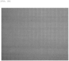
- Fig. 2A is a photograph of the surface of the coating film C in Comparative Example. Note that Fig. 2A shows this photograph in gray scale, and Fig. 2C shows the same photograph as Fig. 2A in binary.
- the coating film C of Comparative Example also had a large variation in film thickness.
- unevenness was slightly observed in appearance.
- the film thickness variation of the coating film C was also sufficiently small.
- unevenness was hardly observed in appearance (See Fig. 2B.
- Fig. 2B shows a photograph of the surface of the coating film C in gray scale
- Fig. 2D shows the same photograph as Fig. 2B in binary.). Further, the film thickness variation of the coating film C was smaller than those in Examples 1 and 2.
- the coating film C was formed using the coating liquid L having a reduced viscosity (the amount of the solvent described above was increased, while other components were left as they were to have a viscosity of 3300 cP).
- the cross section thereof was observed by SEM, sedimentation of the filler (aluminum oxide) was observed (See Fig. 3A.
- Fig. 3A shows the SEM observation photograph in gray scale
- Fig. 3C shows the same photograph as Fig. 3A in binary.).
- the coating film C was obtained with the coating apparatus 1 of Example 3 by using the above-described coating liquid L (viscosity: 4300 cP).
- L viscosity: 4300 cP
- Fig. 3B shows the SEM observation photograph in gray scale
- Fig. 3D shows the same photograph as Fig. 3B in binary.
- the rigidity of the conveying roller 2 and the knife coater 3 may be reduced to cause a bend.
- a reinforcing roller to suppress bend may be provided on the side where the conveying roller 2 and the knife coater 3 bend, and the coating film C may be formed with the coating apparatus 1.
Landscapes
- Chemical & Material Sciences (AREA)
- Life Sciences & Earth Sciences (AREA)
- Engineering & Computer Science (AREA)
- Wood Science & Technology (AREA)
- Materials Engineering (AREA)
- Organic Chemistry (AREA)
- Inorganic Chemistry (AREA)
- Chemical Kinetics & Catalysis (AREA)
- General Chemical & Material Sciences (AREA)
- Application Of Or Painting With Fluid Materials (AREA)
- Paints Or Removers (AREA)
Abstract
Description
- The present invention relates to a coating method and a sheet material.
- Conventionally, various circuit boards have been used. For example,
Patent Literatures 1 and 2 show a circuit board in which a circuit pattern is laminated on a base substrate with an insulating layer interposed therebetween. The insulating layer has a role of securing a withstand voltage between the base substrate and the circuit pattern. When the insulating layer contains a filler, the filler can ensure thermal conductivity of the insulating layer. According to such a circuit board, heat generated by an electronic component provided on the circuit pattern and transferred to the circuit pattern can be transmitted to the base substrate via the insulating layer and released from the base substrate to the outside. - The insulating layer can be obtained, for example, by preparing a sheet material in which a coating film of a composition for forming an insulating layer is formed on the surface of a substrate such as a PET film, and thermally transferring the coating film of the sheet material to the base substrate or the circuit pattern. A coating apparatus and a coating method to form the coating film on the surface of the substrate are disclosed in, for example, Patent Literature 3.
-
- Patent Literature 1:
JP 2009-246079 A - Patent Literature 2:
JP 2013-254921 A - Patent Literature 3:
JP 4857217 B2 - By the way, in recent years, as electronic devices have been advanced in high performance and downsizing, electronic components have an increasing heat generation amount. Accordingly, heat dissipation of an insulating layer is regarded as important. The inventor of the present application conducted studies on this point, and found that an insulating layer having excellent heat dissipation can be obtained when the composition for forming an insulating layer contains a filler in a content ratio greatly higher than before. However, when a coating film is provided on the surface of a substrate by using such a coating liquid in which the content ratio of a filler is increased, conventional coating methods as shown in Patent Literature 3 have difficulties in mass production because the coating film has unevenness in appearance and the coating film has a large film thickness variation.
- In view of such problems, an object of the present invention is to provide a coating method capable of suppressing coating film unevenness and suppressing coating film thickness variation when a coating film is formed on the surface of a substrate by using a coating liquid in which the content ratio of a filler is increased, and a sheet material obtained by the coating method.
- The present invention is a coating method including: using a coating apparatus including a conveying roller that feeds a substrate that is wound and has an elongated shape; a knife coater that is disposed above the conveying roller with a gap from the conveying roller, has a columnar or cylindrical shape, and is provided with a knife portion; and a liquid-reserving member having a one end portion positioned on a side of the conveying roller and partitioning a liquid-reserving space together with the conveying roller, to form a coating film of a coating liquid stored by the liquid-reserving member on a surface of the substrate, wherein the coating liquid contains a resin, a solvent, and a filler, and the filler is contained in a content ratio of 65 to 95 parts by mass with respect to 100 parts by mass of a mixture of the resin and the filler, an outer diameter of the conveying roller is 50 to 270 mm, an outer diameter of the knife coater is 50 to 170 mm, and a distance from the gap to the one end portion of the liquid-reserving member is 1 to 120 mm.
- In the coating method, the solvent is preferably contained in a content ratio of 10 to 50 parts by mass with respect to 100 parts by mass of a mixture of the resin and the filler.
- In the coating method, the coating liquid preferably has a viscosity of 100 to 20000 cP at a temperature of 25°C.
- In the coating method, preferably, the filler is a mixture of boron nitride and aluminum oxide, and the boron nitride is contained in a content ratio of 60 to 90 parts by mass with respect to 100 parts by mass of a mixture of the boron nitride and the aluminum oxide.
- In addition, the present invention is also a sheet material including the substrate and the coating film as described above.
- The coating method of the present invention is capable of suppressing unevenness of a coating film formed on the surface of a substrate, and suppressing coating film thickness variation, when a coating liquid in which the content ratio of a filler is increased is used.
-
-
Fig. 1 is a view illustrating an embodiment of a coating apparatus used in a coating method according to the present invention. -
Fig. 2A is a view (gray scale) relating to unevenness of a coating film. -
Fig. 2B is a view (gray scale) relating to unevenness of a coating film. -
Fig. 2C is a view (a binarized view ofFig. 2A ) relating to unevenness of a coating film. -
Fig. 2D is a view (a binarized view ofFig. 2B ) relating to unevenness of a coating film. -
Fig. 3A is a view (gray scale) relating to a cross section of a coating film by SEM analysis. -
Fig. 3B is a view (gray scale) relating to a cross section of a coating film by SEM analysis. -
Fig. 3C is a view (a binarized view ofFig. 3A ) relating to a cross section of a coating film by SEM analysis. -
Fig. 3D is a view (a binarized view ofFig. 3B ) relating to a cross section of a coating film by SEM analysis. - Hereinafter, an embodiment of the coating method according to the present invention will be described with reference to the accompanying drawings. Note that the views illustrated in the accompanying drawings are schematic, and the thickness and width of each portion, the ratio between the portions, and the like may be different from those actually implemented.
- First, the coating apparatus used in the coating method according to the present invention will be described with reference to
Fig. 1 . In the embodiment, acoating apparatus 1 includes a conveying roller 2, a knife coater 3, and a liquid-reserving member 4, and provides a coating film C on the surface of a substrate W having an elongated shape to form a sheet material including the substrate W and the coating film C. - The conveying roller 2 has a columnar or cylindrical shape, and is configured to rotate in the direction of the illustrated arrow with a motor (not illustrated) or the like. The substrate W is wound around the conveying roller 2, and the substrate W can be fed out with the rotation of the conveying roller 2. In the embodiment, the conveying roller 2 has a length enough to use the substrate W having a width of about 1 m at the maximum. The outer diameter D1 of the conveying roller 2 will be described later.
- The knife coater 3 includes a
main body 3a having a columnar or cylindrical shape, and aknife portion 3b provided on the outer peripheral surface of themain body 3a. As illustrated in the drawing, theknife portion 3b has an edge-like (sharp) cross-sectional shape, and extends long along the axial direction of themain body 3a. The length of the knife coater 3 is set substantially equal to that of the conveying roller 2. The outer diameter D2 of the knife coater 3 will be described later. - As illustrated in the drawing, the knife coater 3 is held above the conveying roller 2 in a state where the
knife portion 3b comes closest to the conveying roller 2 and a gap is made between the tip portion of theknife portion 3b and the outer peripheral surface of the conveying roller 2. The gap is set such that the coating film C having a predetermined thickness is formed on the surface of the substrate W in a state where the substrate W is wound and rotated around the conveying roller 2 (for example, the thickness of the coating film C is about 200 µm). - The liquid-reserving member 4 is disposed in an inclined state with respect to the vertical direction as illustrated in the drawing, and the liquid-reserving member 4 has a one
end portion 4a that is positioned on the side of the conveying roller 2. Note that the reference sign D3 shown inFig. 1 indicates the distance from the gap to the oneend portion 4a (the length of a string connecting the portion closest to theknife portion 3b to the portion closest to the oneend portion 4a on the outer peripheral surface of the conveying roller 2). - As illustrated in the drawing, the
coating apparatus 1 includes a liquid-reserving space S partitioned by the conveying roller 2 and the liquid-reserving member 4. The liquid-reserving space S stores a coating liquid L to form the coating film C. While the coating liquid L is stored in the liquid-reserving space S, the lower portion of the knife coater 3 is immersed in the coating liquid L. - The substrate W is formed of, for example, a peelable PET film or the like.
- The coating liquid L contains a resin, a solvent, and a filler. Examples of the resin include thermosetting resins such as an epoxy resin, a phenol resin, a melamine resin, a urea resin, an unsaturated polyester resin, an alkyd resin, and a cyanate resin. In addition, the resin may be other high thermal conductive resins such as a liquid crystal polymer, a resin having a mesogen skeleton, or an engineering plastic such as polycarbonate, nylon, or polyamide. The resins may be used singly or in combination of two or more kinds thereof. As the solvent, for example, a glycol ether-based solvent (examples thereof include ethyl carbitol, methyl carbitol, and butyl carbitol) is used. The filler is preferably one having excellent insulation properties and high thermal conductivity, and examples thereof include aluminum oxide, boron nitride, silica, aluminum nitride, silicon nitride, and magnesium oxide. In addition, for example, an additive (curing agent) that cures the resin as a main agent is contained in the coating liquid L. The curing agent is not particularly limited as long as it is selected according to the type of the resin and reacts with the resin. When an epoxy resin is used, examples of the curing agent include an amine-based curing agent, an imidazole-based curing agent, and a phenol-based curing agent. In addition, a catalyst may be added to accelerate curing of the resin. For example, when an epoxy resin is used, a phosphorus-based, thiol-based, tertiary amine-based, or imidazole-based catalyst may be used. Regarding the content ratio of the resin contained in the coating liquid L, when a curing agent or a catalyst (additive) is used together with the resin (main agent), the content ratio of the resin is calculated including the curing agent and the catalyst.
- In the coating liquid L of the embodiment, the filler is contained in a content ratio greatly higher than the content ratio where the insulating layer is formed from the coating film C as usual. Specifically, the filler is contained in a content ratio of 65 to 95 parts by mass with respect to 100 parts by mass of a mixture of the resin and the filler contained in the coating liquid L. When the insulating layer of the circuit board is formed from the coating film C obtained from the coating liquid L by greatly increasing the content ratio of the filler as described above, for example, the thermal conductivity of the insulating layer can be 15 W/mk or more, and high thermal conductivity can be imparted to the insulating layer. In consideration of the quality and productivity when the coating film C is formed from the coating liquid L while securing high thermal conductivity obtained as an insulating layer, the filler is contained in a content ratio of more effectively 70 to 90 parts by mass, and further effectively 75 to 85 parts by mass, with respect to 100 parts by mass of a mixture of the resin and the filler. Regarding the filler, from the viewpoint of the quality of the coating film C and the thermal conductivity of the insulating layer, a mixture of boron nitride and aluminum oxide is preferably used, for example. In this case, the boron nitride is contained in a content ratio of effectively 60 to 90 parts by mass, more effectively 65 to 85 parts by mass, and still more effectively 70 to 80 parts by mass, with respect to 100 parts by mass of a mixture of boron nitride and aluminum oxide.
- In view of the quality and productivity of the coating film C, the solvent is contained in a content ratio of preferably 10 to 50 parts by mass, more preferably 20 to 45 parts by mass, and still more preferably 30 to 40 parts by mass, with respect to 100 parts by mass of a mixture of the resin and the filler.
- Next, the coating method for forming the coating film C on the surface of the substrate W using the
coating apparatus 1 will be described. When the coating method is carried out, the substrate W is wound around the conveying roller 2 as illustrated inFig. 1 , and the coating liquid L is stored in the liquid-reserving space S. Then, a motor (not illustrated) or the like is driven to rotate the conveying roller 2 in the direction of the illustrated arrow. As a result, the substrate W is fed in the direction of the illustrated arrow, and accordingly, the coating liquid L passes through the gap between the conveying roller 2 and the knife coater 3, and the coating film C is formed on the surface of the substrate W. - Conventionally, in the
coating apparatus 1, as in the comparative example described later, the diameter D1 of the conveying roller 2 is set to about 300 mm, the diameter D2 of the knife coater 3 is set to about 200 mm, and the distance D3 from the gap between the conveying roller 2 and the knife coater 3 to the oneend portion 4a is set to about 140 mm. When the coating film C is formed on the surface of the substrate W using the coating liquid L in which the content ratio of the filler is increased by using such acoating apparatus 1, the coating film C has unevenness in appearance and the coating film C has an increased film thickness variation. When the coating film C has unevenness, it is difficult to perform automatic foreign matter inspection, which automatically detects foreign matter contained in the coating film C with an appearance inspection machine or the like. Further, when the variation in the film thickness of the coating film C increases, and for example, the coating film C is used as an insulating layer of a circuit board, uniform contact with a base substrate or a circuit pattern may fail to be secured. - As a result of repeated studies on such unevenness and film thickness variation of the coating film C, it is inferred that the coating liquid L used has an increased content ratio of the filler, and otherwise has a reduced content ratio of the resin, which is one of the factors. That is, when the substrate W is fed, the coating liquid L is continuously supplied to the gap between the conveying roller 2 and the knife coater 3. Therefore, in the gap, a compressive force is strongly applied by the sequentially supplied coating liquid L. Here, since the fluidity of the resin is higher than that of the filler, the inventor of the present application has inferred that the compressive force acts to squeeze the resin from the coating liquid L, which leads to occurrence of unevenness and variation in film thickness. In addition, since the content ratio of the filler is increased, it is presumed that one of the factors is that the filler easily settles in the storing liquid-reserving space S.
- For this reason, the inventor of the present application considered that the compressive force is reduced by reducing the amount of the coating liquid L supplied to the gap between the conveying roller 2 and the knife coater 3 as much as possible, whereby the mixed state of the resin and the filler is hardly disturbed even when the coating liquid L passes through the gap. That is, the inventors considered that it is effective to reduce the amount of the coating liquid L supplied to the gap between the conveying roller 2 and the knife coater 3 by reducing the outer diameter of the conveying roller 2 and the knife coater 3. In addition, in order to suppress the sedimentation of the filler in the liquid-reserving space S and reduce the amount of the coating liquid L, the inventor considered that it is effective to reduce the volume of the liquid-reserving space S by bringing the liquid-reserving member 4 close to the conveying roller 2.
- Further, as a result of repeated studies under such considerations, it has been found that when the outer diameter D1 of the conveying roller 2 is 50 to 270 mm, the outer diameter D2 of the knife coater 3 is 50 to 170 mm, and the distance D3 from the gap to the one
end portion 4a is 1 to 120 mm, unevenness occurring in the coating film C is suppressed, and film thickness variation of the coating film C is also suppressed. As a result of further studies, it has been found that the outer diameter D1 of the conveying roller 2 is more preferably 75 to 250 mm, and still more preferably 100 to 200 mm in order to suppress the occurrence of such unevenness and suppress the variation in film thickness in the coating film C. It has been also found that the outer diameter D2 of the knife coater 3 is more preferably 75 to 170 mm, and still more preferably 100 to 150 mm. Then, it has been found that the distance D3 from the gap to the oneend portion 4a is more preferably 1 to 100 mm, and still more preferably 1 to 50 mm. - The inventor of the present application has also studied the viscosity of the coating liquid L in addition to the study of the diameter D1 and the like of the conveying roller 2 in the
coating apparatus 1. This is presumably because the coating liquid L having a reduced viscosity can prevent the coating film C from having unevenness in appearance. However, when the viscosity of the coating liquid L is reduced, sedimentation of the filler is observed in the formed coating film C. For this reason, as a result of repeated studies on the viscosity capable of suppressing sedimentation of the filler while suppressing occurrence of unevenness, it has been found that when the viscosity of the coating liquid L is 100 to 20000 cP at a temperature of 25°C, occurrence of unevenness and sedimentation of the filler can be suppressed. As a result of further studies on this point, it has been found that the viscosity is more preferably 2000 to 10000 cP, and still more preferably 4000 to 6000 cP. The viscosity is a value measured at a shear rate of 8 (1/s) using a B-type viscometer (Brookfield rotational viscometer, digital viscometer DV2T (manufactured by EKO INSTRUMENTS CO., - Examples of the present invention will be described below. Note that the present invention is not limited to Examples.
- A PET film was prepared as the substrate W. As the coating liquid L, a composition containing a resin (a main agent and an additive (curing agent)), a solvent, and a filler was prepared. The content ratio of each component with respect to the coating liquid L (parts by mass of each component with respect to 100 parts by mass of the coating liquid L) is also shown.
- [Main agent]
Bisphenol A epoxy resin (Trade name: EXA-850CRP; manufactured by DIC Corporation), 11.2 parts by mass - [Curing agent]
4,4'-diaminodiphenyl sulfone (Trade name: SEIKACURE-S; manufactured by Wakayama Seika Kogyo Co., Ltd.), 4.2 parts by mass - [Solvent]
Ethyl carbitol (Trade name: ethyl carbitol; manufactured by SANKYO CHEMICAL CO., LTD.), 27.6 parts by mass - [Filler (A)]
Boron nitride (BN) (Trade name: HP-40, particle shape: aggregation, average particle diameter (d50): 36 µm; manufactured by Mizushima Ferroalloy Co., Ltd.), 43 parts by mass - [Filler (B)]
Aluminum oxide (Trade name: AS20, particle shape: rounded, average particle diameter (d50): 22 µm; manufactured by SHOWA DENKO K.K.), 14 parts by mass - That is, in the prepared coating liquid L, the content ratio of the filler (A) and the filler (B) is 78.7 parts by mass with respect to 100 parts by mass of the mixture of the resin (main agent and curing agent), the filler (A), and the filler (B), and the content ratio of the solvent is 38.1 parts by mass with respect to 100 parts by mass of the mixture of the resin (main agent and curing agent), the filler (A), and the filler (B). The content ratio of the filler (A) is 75.4 parts by mass with respect to 100 parts by mass of the mixture of the filler (A) and the filler (B).
- The viscosity of the coating liquid L is 4300 cP in terms of a value measured at a shear rate of 8 (1/s) using a B-type viscometer (Brookfield rotational viscometer, digital viscometer DV2T (manufactured by EKO INSTRUMENTS CO., LTD.)).
- The diameter D1 of the conveying roller 2, the diameter D2 of the knife coater 3, and the distance D3 from the gap between the conveying roller 2 and the knife coater 3 to the one
end portion 4a in thecoating apparatus 1 are as in Comparative Example and Examples 1 to 3 shown in Table 1 below. When the coating film C was formed from the substrate W and the coating liquid L using thecoating apparatuses 1 of Comparative Example and Examples 1 to 3, the results were as shown in Table 1.[Table 1] Comparative Example Example 1 Example 2 Example 3 Coating apparatus D1(mm) 300 200 200 160 D2(mm) 200 80 120 120 D3(mm) 144 76.7 75 50 Coating width to substrate (mm) 510 155 510 510 Coating film Appearance Poor Good Good Excellent Film thickness (µ m) Average value 230.0 183.1 233.8 239.6 Maximum value 289.0 188.5 238.7 244.1 Minimum value 208.0 180.0 231.0 237.1 Maximum value - Minimum value 81.0 8.5 7.7 7.0 - In Table 1, the "Appearance" is rated as follows.
- Excellent: Unevenness is hardly observed in the coating film C in appearance.
- Good: Some unevenness is observed in the coating film C in appearance.
- Poor: Much unevenness is observed in the coating film C in appearance.
- As shown in Table 1, much unevenness was observed in the appearance of the coating film C obtained with the
coating apparatus 1 of Comparative Example.Fig. 2A is a photograph of the surface of the coating film C in Comparative Example. Note thatFig. 2A shows this photograph in gray scale, andFig. 2C shows the same photograph asFig. 2A in binary. The coating film C of Comparative Example also had a large variation in film thickness. On the other hand, in the coating films C obtained with thecoating apparatuses 1 of Examples 1 and 2, unevenness was slightly observed in appearance. The film thickness variation of the coating film C was also sufficiently small. In the coating film C obtained with thecoating apparatus 1 of Example 3, unevenness was hardly observed in appearance (SeeFig. 2B. Fig. 2B shows a photograph of the surface of the coating film C in gray scale, andFig. 2D shows the same photograph asFig. 2B in binary.). Further, the film thickness variation of the coating film C was smaller than those in Examples 1 and 2. - As described above, depending on the viscosity of the coating liquid L, sedimentation of the filler is observed in the formed coating film C. Here, using the
coating apparatus 1 of Example 3, the coating film C was formed using the coating liquid L having a reduced viscosity (the amount of the solvent described above was increased, while other components were left as they were to have a viscosity of 3300 cP). When the cross section thereof was observed by SEM, sedimentation of the filler (aluminum oxide) was observed (SeeFig. 3A. Fig. 3A shows the SEM observation photograph in gray scale, andFig. 3C shows the same photograph asFig. 3A in binary.). On the other hand, the coating film C was obtained with thecoating apparatus 1 of Example 3 by using the above-described coating liquid L (viscosity: 4300 cP). When the cross section thereof was observed by SEM, sedimentation of the filler was not observed, and the result was preferable (SeeFig. 3B. Fig. 3B shows the SEM observation photograph in gray scale, andFig. 3D shows the same photograph asFig. 3B in binary.). - Although an embodiment of the present invention has been described above, the present invention is not limited to the specific embodiment, and various modifications and changes can be made within the scope of the gist of the present invention described in the claims unless otherwise limited in the above description. In addition, the effects of the above embodiment are merely examples of the effects caused by the present invention, and do not mean that the effects of the present invention are limited to the above effects.
- For example, when the outer diameter D1 of the conveying roller 2 and the outer diameter D2 of the knife coater 3 are reduced, the rigidity of the conveying roller 2 and the knife coater 3 may be reduced to cause a bend. In such a case, for example, a reinforcing roller to suppress bend may be provided on the side where the conveying roller 2 and the knife coater 3 bend, and the coating film C may be formed with the
coating apparatus 1. -
- 1
- Coating apparatus
- 2
- Conveying roller
- 3
- Knife coater
- 3b
- Knife portion
- 4
- Liquid-reserving member
- 4a
- One end portion
- C
- Coating film
- L
- Coating liquid
- S
- Liquid-reserving space
- W
- Substrate
Claims (5)
- A coating method comprising: using a coating apparatus including a conveying roller that feeds a substrate that is wound and has an elongated shape; a knife coater that is disposed above the conveying roller with a gap from the conveying roller, has a columnar or cylindrical shape, and is provided with a knife portion; and a liquid-reserving member having a one end portion positioned on a side of the conveying roller and partitioning a liquid-reserving space together with the conveying roller, to form a coating film of a coating liquid stored by the liquid-reserving member on a surface of the substrate, whereinthe coating liquid contains a resin, a solvent, and a filler, and the filler is contained in a content ratio of 65 to 95 parts by mass with respect to 100 parts by mass of a mixture of the resin and the filler,an outer diameter of the conveying roller is 50 to 270 mm,an outer diameter of the knife coater is 50 to 170 mm, anda distance from the gap to the one end portion of the liquid-reserving member is 1 to 120 mm.
- The coating method according to claim 1, wherein the solvent is contained in a content ratio of 10 to 50 parts by mass with respect to 100 parts by mass of a mixture of the resin and the filler.
- The coating method according to claim 1 or 2, wherein the coating liquid has a viscosity of 100 to 20000 cP at a temperature of 25°C.
- The coating method according to any one of claims 1 to 3, whereinthe filler is a mixture of boron nitride and aluminum oxide, andthe boron nitride is contained in a content ratio of 60 to 90 parts by mass with respect to 100 parts by mass of a mixture of the boron nitride and the aluminum oxide.
- A sheet material comprising the substrate and the coating film according to any one of claims 1 to 4.
Applications Claiming Priority (2)
| Application Number | Priority Date | Filing Date | Title |
|---|---|---|---|
| JP2022060185 | 2022-03-31 | ||
| PCT/JP2023/000368 WO2023188677A1 (en) | 2022-03-31 | 2023-01-11 | Coating method and sheet material |
Publications (2)
| Publication Number | Publication Date |
|---|---|
| EP4501469A1 true EP4501469A1 (en) | 2025-02-05 |
| EP4501469A4 EP4501469A4 (en) | 2025-07-16 |
Family
ID=87882241
Family Applications (1)
| Application Number | Title | Priority Date | Filing Date |
|---|---|---|---|
| EP23778717.1A Pending EP4501469A4 (en) | 2022-03-31 | 2023-01-11 | Coating method and sheet material |
Country Status (5)
| Country | Link |
|---|---|
| US (1) | US20250215246A1 (en) |
| EP (1) | EP4501469A4 (en) |
| JP (1) | JP7339472B1 (en) |
| KR (1) | KR20240154626A (en) |
| CN (1) | CN118946414A (en) |
Family Cites Families (15)
| Publication number | Priority date | Publication date | Assignee | Title |
|---|---|---|---|---|
| JPS4857217U (en) | 1971-11-01 | 1973-07-21 | ||
| JP2000117170A (en) * | 1998-10-13 | 2000-04-25 | Konica Corp | Method and apparatus for coating high viscosity coating- liquid |
| JP4163457B2 (en) * | 2002-07-08 | 2008-10-08 | 株式会社日本触媒 | Method for producing microcapsule-containing sheet |
| JP2006128649A (en) * | 2004-09-30 | 2006-05-18 | Nitta Ind Corp | Electromagnetic interference suppressor and method for manufacturing the same |
| JP4857217B2 (en) * | 2007-08-21 | 2012-01-18 | 日東電工株式会社 | Coating method and coating apparatus |
| JP2009246079A (en) | 2008-03-31 | 2009-10-22 | Furukawa Electric Co Ltd:The | Semiconductor package and method of manufacturing the same |
| KR101123198B1 (en) * | 2009-11-30 | 2012-03-19 | (주)프로템 | Coating type-selectable coating apparatus |
| KR20110062339A (en) * | 2009-12-03 | 2011-06-10 | 주식회사 아모 | Comma coating machine |
| JP5487010B2 (en) * | 2010-05-27 | 2014-05-07 | 日本発條株式会社 | Circuit board laminate and metal base circuit board |
| JP5816901B2 (en) * | 2011-10-20 | 2015-11-18 | 新神戸電機株式会社 | Coating equipment |
| JP2013254921A (en) | 2012-06-08 | 2013-12-19 | Denki Kagaku Kogyo Kk | Circuit board and electronic-component mounting board |
| KR20160010792A (en) * | 2014-07-18 | 2016-01-28 | (주)나노피엔씨 | comma coating device and gap control method between comma roll and master roll for the same |
| JP2020175332A (en) * | 2019-04-18 | 2020-10-29 | 住友化学株式会社 | Coating equipment, coating method and manufacturing method of laminate |
| JP7283208B2 (en) * | 2019-04-26 | 2023-05-30 | Agc株式会社 | Powder dispersion, method for producing laminate, method for producing laminate and printed circuit board |
| JP2021181068A (en) * | 2020-05-20 | 2021-11-25 | 昭和電工株式会社 | Manufacturing method for sheet-like article |
-
2023
- 2023-01-11 US US18/851,942 patent/US20250215246A1/en active Pending
- 2023-01-11 JP JP2023530890A patent/JP7339472B1/en active Active
- 2023-01-11 CN CN202380030146.8A patent/CN118946414A/en active Pending
- 2023-01-11 EP EP23778717.1A patent/EP4501469A4/en active Pending
- 2023-01-11 KR KR1020247032098A patent/KR20240154626A/en active Pending
Also Published As
| Publication number | Publication date |
|---|---|
| KR20240154626A (en) | 2024-10-25 |
| JPWO2023188677A1 (en) | 2023-10-05 |
| EP4501469A4 (en) | 2025-07-16 |
| CN118946414A (en) | 2024-11-12 |
| JP7339472B1 (en) | 2023-09-05 |
| US20250215246A1 (en) | 2025-07-03 |
Similar Documents
| Publication | Publication Date | Title |
|---|---|---|
| JP6843460B2 (en) | Thermal conductivity composition, thermal conductive member, manufacturing method of thermal conductive member, heat dissipation structure, heat generation composite member, heat dissipation composite member | |
| KR101397221B1 (en) | Insulation resin composition for printed circuit board having thermal conductivity and improved electrical properties, insulating film, prepreg and printed circuit board | |
| TWI480369B (en) | Thermally conductive sheet | |
| KR20130091683A (en) | Thermal conductive sheet | |
| EP2571342A1 (en) | Method of manufacturing metal-base substrate and method of manufacturing circuit board | |
| JP2013254880A (en) | Heat-conductive insulator sheet, metal based board and circuit board, and manufacturing method thereof | |
| JP2009049062A (en) | Method for manufacturing metal base circuit board and metal base circuit board | |
| TWI701126B (en) | Manufacturing method and manufacturing device of fiber reinforced plastic precursor | |
| CN104427750A (en) | Insulating film for printed circuit board and products having the same | |
| JP5266461B2 (en) | Resin for electronic board filling | |
| TW201905055A (en) | Resin material, manufacturing method of resin material, and laminated body | |
| KR101626237B1 (en) | Method for manufacturing thermally conductive sheet | |
| US20250215246A1 (en) | Coating method and sheet material | |
| JP2002275433A (en) | Adhesive film | |
| EP4502000A1 (en) | Thermosetting resin composition, resin cured product and composite molded body | |
| TW201900553A (en) | Insulating sheet and laminate | |
| WO2017086474A1 (en) | Metal base substrate, circuit board, and substrate with heat-generating body mounted thereon | |
| TWI855571B (en) | Application method and sheet material | |
| JP7069967B2 (en) | Heat dissipation board | |
| US20190345325A1 (en) | Resin composition for printed circuit board and integrated circuit package, and product using the same | |
| JP6645496B2 (en) | Method and apparatus for producing FRP precursor | |
| JP2006310788A (en) | Method of manufacturing resin-filled substrate | |
| CN101934618A (en) | Thermocompression release sheet for aeolotropism conductive film and method for producing the same | |
| EP4134398A1 (en) | Method for producing resin composition layer, resin composition layer produced by said production method, and composite molded article including said resin composition layer | |
| JP5821845B2 (en) | Resin composition used for formation of resin layer constituting metal base substrate, metal base substrate, and method of manufacturing metal base substrate |
Legal Events
| Date | Code | Title | Description |
|---|---|---|---|
| STAA | Information on the status of an ep patent application or granted ep patent |
Free format text: STATUS: THE INTERNATIONAL PUBLICATION HAS BEEN MADE |
|
| PUAI | Public reference made under article 153(3) epc to a published international application that has entered the european phase |
Free format text: ORIGINAL CODE: 0009012 |
|
| STAA | Information on the status of an ep patent application or granted ep patent |
Free format text: STATUS: REQUEST FOR EXAMINATION WAS MADE |
|
| 17P | Request for examination filed |
Effective date: 20240927 |
|
| AK | Designated contracting states |
Kind code of ref document: A1 Designated state(s): AL AT BE BG CH CY CZ DE DK EE ES FI FR GB GR HR HU IE IS IT LI LT LU LV MC ME MK MT NL NO PL PT RO RS SE SI SK SM TR |
|
| DAV | Request for validation of the european patent (deleted) | ||
| DAX | Request for extension of the european patent (deleted) | ||
| A4 | Supplementary search report drawn up and despatched |
Effective date: 20250617 |
|
| RIC1 | Information provided on ipc code assigned before grant |
Ipc: B05D 1/28 20060101AFI20250611BHEP Ipc: B05D 3/00 20060101ALI20250611BHEP Ipc: B05D 7/00 20060101ALI20250611BHEP Ipc: B05D 7/24 20060101ALI20250611BHEP Ipc: C09D 201/00 20060101ALI20250611BHEP Ipc: C09D 7/61 20180101ALI20250611BHEP Ipc: B05C 3/18 20060101ALI20250611BHEP Ipc: B05C 11/02 20060101ALI20250611BHEP Ipc: B05C 11/04 20060101ALI20250611BHEP Ipc: B05D 1/18 20060101ALN20250611BHEP |