EP4501466A1 - Slit die - Google Patents
Slit die Download PDFInfo
- Publication number
- EP4501466A1 EP4501466A1 EP22935712.4A EP22935712A EP4501466A1 EP 4501466 A1 EP4501466 A1 EP 4501466A1 EP 22935712 A EP22935712 A EP 22935712A EP 4501466 A1 EP4501466 A1 EP 4501466A1
- Authority
- EP
- European Patent Office
- Prior art keywords
- manifold
- small
- coating liquid
- width direction
- slit
- Prior art date
- Legal status (The legal status is an assumption and is not a legal conclusion. Google has not performed a legal analysis and makes no representation as to the accuracy of the status listed.)
- Pending
Links
Images



Classifications
-
- B—PERFORMING OPERATIONS; TRANSPORTING
- B05—SPRAYING OR ATOMISING IN GENERAL; APPLYING FLUENT MATERIALS TO SURFACES, IN GENERAL
- B05C—APPARATUS FOR APPLYING FLUENT MATERIALS TO SURFACES, IN GENERAL
- B05C5/00—Apparatus in which liquid or other fluent material is projected, poured or allowed to flow on to the surface of the work
- B05C5/02—Apparatus in which liquid or other fluent material is projected, poured or allowed to flow on to the surface of the work the liquid or other fluent material being discharged through an outlet orifice by pressure, e.g. from an outlet device in contact or almost in contact, with the work
- B05C5/0254—Coating heads with slot-shaped outlet
-
- B—PERFORMING OPERATIONS; TRANSPORTING
- B05—SPRAYING OR ATOMISING IN GENERAL; APPLYING FLUENT MATERIALS TO SURFACES, IN GENERAL
- B05C—APPARATUS FOR APPLYING FLUENT MATERIALS TO SURFACES, IN GENERAL
- B05C11/00—Component parts, details or accessories not specifically provided for in groups B05C1/00 - B05C9/00
- B05C11/10—Storage, supply or control of liquid or other fluent material; Recovery of excess liquid or other fluent material
-
- B—PERFORMING OPERATIONS; TRANSPORTING
- B05—SPRAYING OR ATOMISING IN GENERAL; APPLYING FLUENT MATERIALS TO SURFACES, IN GENERAL
- B05C—APPARATUS FOR APPLYING FLUENT MATERIALS TO SURFACES, IN GENERAL
- B05C5/00—Apparatus in which liquid or other fluent material is projected, poured or allowed to flow on to the surface of the work
- B05C5/02—Apparatus in which liquid or other fluent material is projected, poured or allowed to flow on to the surface of the work the liquid or other fluent material being discharged through an outlet orifice by pressure, e.g. from an outlet device in contact or almost in contact, with the work
- B05C5/027—Coating heads with several outlets, e.g. aligned transversally to the moving direction of a web to be coated
Definitions
- the present invention relates to a slit die for applying a coating liquid on a substrate.
- battery electrode plates are manufactured by coating and drying a surface of a substrate, such as aluminum foil or copper foil, with a slurry (hereinafter referred to as coating liquid) obtained by mixing an active material, a binder, and a conductive assistant, in a solvent.
- a slurry hereinafter referred to as coating liquid
- a coating device in this manufacturing process continuously transports a substrate using a roll-to-roll method and causes a slit die to discharge a coating liquid, thereby applying the coating liquid on the substrate and forming a coating film (for example, Patent Document 1).
- Application methods include single-line coating, where the coating liquid is applied in a wide strip across the width direction of the substrate, and multi-line coating (hereinafter referred to as stripe coating) where the coating liquid is applied in a stripe pattern across the width direction of the substrate.
- Patent Document 1 Japanese Laid-Open Patent Application Publication No. 2022-041501
- a conventional slit die is formed elongated in the width direction (hereinafter referred to as the width direction) of a substrate 960 (refer to Figure 5 ), as shown in Figures 4(a) and 4(b) , and comprises a manifold 910, which is a space that holds a coating liquid, supply ports 950, a plurality of which are formed in the manifold 910 so as to be arranged in the width direction and supply the coating liquid to the manifold 910, a slit 920 connected to the manifold 910 and that is elongated in the width direction, and a discharge port 930 that discharges the coating liquid from the manifold 910 via the slit 920.
- a manifold 910 which is a space that holds a coating liquid
- supply ports 950 a plurality of which are formed in the manifold 910 so as to be arranged in the width direction and supply the coating liquid to the manifold 910
- a slit 920 connected to the man
- a shim 940 that partitions the slit 920 into a plurality of spaces in the width direction is provided in the slit 920, as shown in Figures 4(a) and 4(b) , and the shim 940 partitions the slit 920 in the width direction, thereby applying the coating liquid on the substrate 960 in a stripe pattern in the width direction.
- coating liquid that is supplied to the manifold 910 from each of the plurality of supply ports 950 flows into each of the spaces of the slit 920 partitioned by the shim 940 and is discharged from the discharge port 930.
- the coating liquid supplied from the supply port 950 located near the shim 940, among the plurality of supply ports 950 flows in the width direction while avoiding where the shim 940 is located.
- This coating liquid collides, inside the manifold 910, with coating liquid that is supplied from the other supply ports 950 and that flows toward each of the adjacent spaces of the slit 920.
- an object of the present invention is to provide a slit die that can make the width-direction shape of the coating film more uniform compared to conventional methods, when the coating film is formed in a stripe pattern in the width direction.
- a slit die of the present invention for solving the problem described above is a slit die configured to apply a coating liquid on a substrate, the slit die comprising a manifold that is formed elongated in a width direction of the substrate and is a space that is configured to hold the coating liquid, a plurality of supply ports that are provided in the manifold so as to be arranged in the width direction and are configured to supply the coating liquid to the manifold, a slit that is connected to the manifold and is elongated in the width direction, a discharge port that is configured to discharge the coating liquid from the manifold via the slit, a shim that partitions the slit into a plurality of spaces in the width direction and forms small slits, and a partition portion that partitions the manifold into a plurality of spaces in the width direction and forms small manifolds, the partition portion being disposed at a position that partitions the manifold such that at least one of the supply ports is located in each small
- the slit die described above has a partition portion, and this partition portion partitions the manifold in the width direction of the substrate such that one small manifold connects to one small slit, thereby preventing the coating liquid from moving between adjacent small manifolds, so that it is possible to suppress collisions of the coating liquid in the manifold.
- the coating liquid flows into each small slit from each small manifold so as to be uniform in the width direction of the substrate, and is discharged from the discharge port.
- the partition portion may be formed so as to form a communication portion that connects, in the width direction, each of the small manifolds that are adjacent to each other, and the communication portion may be formed such that pressure loss experienced by the coating liquid, which is supplied from the supply ports to each of the small manifolds, when flowing from the small manifolds to the adjacent small manifolds via the communication portion is greater than the pressure loss experienced by the coating liquid when flowing from the small manifolds to the discharge port via the small slits.
- At least one of the small manifolds may be provided with an exhaust means for exhausting air that is present in the manifold.
- the manifold may be provided with a plurality of partition attaching portions for attaching the partition portion, and the partition portion may be formed so as to be detachable with respect to each of the partition attaching portions.
- the slit die of the present invention it is possible to make the width-direction shape of the coating film uniform, when the coating film is formed in a stripe pattern in the width direction.
- the three axes of a Cartesian coordinate system are X, Y, and Z, wherein the horizontal directions are referred to as the X-axis direction and the Y-axis direction, and the direction perpendicular to the XY plane (i.e., the vertical direction) is referred to as the Z-axis direction.
- Figure 1 is a schematic diagram showing a coating device 100 equipped with a slit die 2 according to the present embodiment.
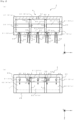
- Figure 2 is a diagram for explaining the slit die 2 according to the present embodiment; (a) is a cross-sectional view taken along the line indicated by arrow a in Figure 1 , and (b) is a cross-sectional view taken along the line indicated by arrow b in Figure 1 .
- Figure 3 is a diagram showing a coating film M formed by the slit die 2 according to the present embodiment.
- the coating device 100 comprises a transport means 1 for transporting a substrate W, the slit die 2 for applying a coating liquid on the substrate W, and a supply means 3 for supplying the coating liquid to the slit die 2.
- the coating device 100 in the present embodiment uses the slit die 2 to apply coating liquid on a prescribed surface of the substrate W, which is transported by the transport means 1, to form the coating film M (refer to Figure 3 ).
- the substrate W in the present embodiment is a metal foil that will become a battery electrode plate of a battery, such as a lithium ion battery; aluminum foil, etc., is used when forming a positive electrode, and a copper foil, etc., is used when forming a negative electrode.
- This substrate W is a strip-shaped sheet that is elongated in one direction, and is transported by the transport means 1.
- a coating liquid in the present embodiment is, for example, a slurry containing an active material, a binder, a conductive assistant, and a solvent, and is used as a material (so-called electrode material) of a battery electrode plate for a battery, such as a lithium ion battery.
- the coating film M is formed on the substrate W by applying this coating liquid to the substrate W.
- the transport means 1 in the present embodiment is for transporting the substrate W which employs the roll-to-roll method in which the substrate W is transported by the rotation of a plurality of rollers.
- the transport speed of the substrate W by this transport means 1 is controlled by an undiagrammed control unit.
- the control unit is, for example, a general-purpose computer.
- only a coating roller 11 that guides the substrate W to the location where the coating liquid is applied is shown in Figure 1 .
- the coating roller 11 is disposed so as to face the slit die 2 and to be a prescribed distance away from a discharge port 23, described further below, at the time that the slit die 2 applies the coating liquid. Therefore, it is possible to transport the substrate W while maintaining a constant distance from the slit die 2.
- the slit die 2 in the present embodiment is for applying a coating liquid on the substrate W that is transported to form the coating film M.
- the slit die 2 is formed elongated along the width direction of the substrate W (Y-axis direction in Figure 1 ).
- the above-mentioned coating roller 11 is disposed at a prescribed distance from a coating unit 2 such that the rotational axis direction of the coating roller 11 and the width direction of the coating unit 2 are parallel to each other.
- the width direction of the substrate W is referred to as the width direction.
- the slit die 2 of the present embodiment is configured by combining a first split body 24 having a tapered first lip 24a, as shown in Figure 1 , and a second split body 25 having a tapered second lip 25a, with a shim plate 26 sandwiched therebetween.
- a manifold 21 composed of a space that is elongated in the width direction and that holds the coating liquid, and a slit 22 that is connected to this manifold 21 and that is wide in the width direction.
- the discharge port 23, which is the open end of the slit 22, is formed between the first lip 24a and the second lip 25a. That is, the first manifold 21 and the discharge port 23 are connected via the slit 22.
- the manifold 21 in the present embodiment is formed in an essentially cylindrical shape extending in the width direction, as shown in Figures 1 and 2(a) . Coating liquid is supplied to this manifold 21 by the supply means 3, described further below.
- the dimension of the slit 22 that is connected to the manifold 21 is determined by the inner dimension L (refer to Figure 2(b) ) of the shim plate 26.
- the slit die 2 applies, on the substrate W, coating liquid having essentially the same width-direction dimension as the dimension of the slit 22.
- the pressure inside the manifold 21 can be adjusted by changing the thickness of the shim plate 26, and the coating film M that has various thicknesses can be formed on the substrate W with this adjustment.
- the discharge port 23 faces the coating roller 11 with the substrate W sandwiched therebetween. That is, the discharge port 23 faces the substrate W on the front surface side of the substrate W.
- the supply means 3 in the present embodiment is for supplying coating liquid to the slit die 2.
- the supply means 3 has a tank 31 for storing the coating liquid, a supply path 32 that connects the tank 31 to the slit die 2, a supply port 33 that connects the supply path 32 from outside of the slit die 2 to the manifold 21, and an undiagrammed pump that feeds the coating liquid, as shown in Figures 1 and 2(a) .
- a plurality of the supply ports 33 are formed at the bottom of the manifold 21, arranged in the width direction, as shown in Figures 2(a) and 2(b) .
- the supply path 32 is connected to each of these supply ports 33. That is, the supply means 3 supplies the coating liquid to the manifold 21 from a plurality of locations.
- the supply path 32 that is connected to each of the supply ports 33 may be provided individually for each of the supply ports 33, or one supply path 32 extending from the tank 31 may branch out before reaching the supply port 33.
- the pump is configured to be able to adjust the flow rate of the coating liquid to be fed to the supply port 33 via the supply path 32.
- this pump is provided to each of the supply paths 32 connected to each of the supply ports 33 so that the flow rate of the coating liquid to be fed from the tank 31 to each of the supply ports 33 can be adjusted. As a result, it is possible to adjust the flow rate of the coating liquid to be fed to the manifold 21 across the width direction.
- the slit die 2 in the present embodiment forms the coating film M in a stripe pattern in the width direction.
- Forming the coating film M in a stripe pattern in the width direction here means to form the coating film M in the width direction of the substrate W (Y-axis direction in Figure 3 ) such that the substrate W has a plurality of coated areas T where the coating film M is formed, as shown in Figure 3 , and uncoated areas N where the coating film M is not formed between the plurality of coated areas T.
- the slit die 2 in the present embodiment comprises a shim 4 that partitions the slit 22 into a plurality of spaces in the width direction, as shown in Figures 2(a) and 2(b) .
- the shim 4 in the present embodiment is a block that extends from the start end of the slit 22, which is the boundary between the manifold 21 and the slit 22, to the open end, and has the same thickness as the above-mentioned shim plate 26 in the height direction, as shown in Figure 2(a) .
- the present embodiment an example in which two of the shims 4 are used will be described. These two shims 4 are sandwiched by the first split body 24 and the second split body 25 so as to be arranged in the width direction, thereby being fixed in a state of partitioning the slit 22 into a plurality of spaces in the width direction.
- the space of the slit 22 is partitioned into a small slit 41a, a small slit 41b, and a small slit 41 c, as shown in Figures 2(a) and 2(b) .
- the coating liquid flows into each of the small slit 41a, the small slit 41b, and the small slit 41c, and the coating liquid is applied from the discharge ports 23, which are the open ends thereof. That is, the coating liquid is applied from where the shim 4 is not present, and the coating liquid is not applied from where the shim 4 is present. Therefore, it is possible to form the coating film M on the substrate W in a stripe pattern in the width direction.
- the width of the coating film M can be adjusted by changing the width-direction dimension of the shim 4. That is, it is possible to adjust the widths of the coated areas T and the uncoated areas N in the width direction of the substrate W.
- the position where the shim 4 is fixed that is, the position where the shim 4 is sandwiched between the first split body 24 and the second split body 25 may be changed to adjust the width of the coating film M. That is, it is possible to adjust the widths of the coated areas T and the uncoated areas N in the width direction of the substrate W.
- the slit die 2 can form, on the substrate W, the coating film M in a stripe pattern in the width direction.
- the slit die 2 in the present embodiment comprises the partition portion 5, which partitions the manifold 21 into a plurality of spaces in the width direction, as shown in Figures 2(a) and 2(b) .
- the partition portion 5 in the present embodiment is a block that is formed to match the shape of the manifold 21.
- the manifold 21 in the present embodiment is formed in an essentially cylindrical shape extending in the width direction.
- the partition portion 5 is formed in an essentially columnar shape, and is disposed such that the outer circumferential surface of this column faces the inner circumferential surface of the manifold 21, as shown in Figures 2(a) and 2(b) .
- the width-direction dimension of the partition portion 5 is formed to be smaller than, or the same as, the width-direction dimension of the above-mentioned shim 4.
- the number and positions of the partition portions 5 to be disposed are linked to the number and positions of the shims 4 to be disposed.
- two of the partition portions 5 are disposed in the manifold 21. These two partition portions 5 are disposed so as to be arranged in the width direction of the manifold 21, as shown in Figures 2(a) and 2(b) , thereby partitioning the space of the manifold 21 in the width direction into a small manifold 51a, a small manifold 51b, and a small manifold 51c.
- the partition portion 5 is arranged to partition the manifold 21 such that one small manifold 51 is connected to one small slit 41. That is, the partition portion 5 is disposed so as to face the shim 4 in a direction (X-axis direction in Figure 2(a) ) in which the coating liquid flows from the manifold 21 to the discharge port 23. When viewed from the direction of the discharge port 23, the partition portion 5 is preferably arranged such that the partition portion 5 is hidden by the shim 4.
- the small slit 41a and the small manifold 51a, the small slit 41b and the small manifold 51b, and the small slit 41c and the small manifold 51c are respectively connected to each other.
- the partition portion 5 is disposed such that at least one of the supply ports 33 is located in each of the small manifolds 51.
- the partition portion 5 in the present embodiment is formed so as to form a communication portion 52 that connects, in the width direction, the small manifolds 51 that are adjacent to each other, as shown in Figures 2(a) and 2(b) .
- the communication portion 52 in the present embodiment is a gap, and is referred to as gap portion 52 in the description hereinbelow.
- the partition portion 5 is formed in a shape in which the above-mentioned inner circumferential surface of the manifold 21 and a portion of the outer circumferential surface of the partition portion 5 face each other with a prescribed gap therebetween.
- the gap portion 52 is formed between the inner circumferential surface of the manifold 21 and a portion of the outer circumferential surface of the partition portion 5, and the adjacent small manifolds 51, that is, the small manifold 51a, the small manifold 51b, and the small manifold 51c are connected via the gap portion 52.
- a pump included in the supply means 3 is used to adjust the flow rate of the coating liquid that is supplied from the tank 31 to each of the supply ports 33 such that the flow rate is uniform for each of the small manifolds 51. That is, the amount of the coating liquid in each of the small manifolds 51 becomes uniform.
- the gap portion 52 is formed such that the pressure loss experienced by the coating liquid, which is supplied from the supply ports 33 to each of the small manifolds 51, when flowing from the small manifolds 51 to the adjacent small manifolds 51 via the gap portion 52 is greater than the pressure loss experienced by the coating liquid when flowing from the small manifolds 51 to the discharge port 23 via the small slits 41.
- At least the cross sectional area of the gap between the inner circumferential surface of the manifold 21 and the outer circumferential surface of the partition portion 5, which forms the gap portion 52, is set to be smaller than the cross sectional area of the small slit 41.
- the dimension of the gap portion 52 that is, the distance between the inner circumferential surface of the manifold 21 and the outer circumferential surface of the partition portion 5, to be as small as possible; preferably, the dimension is such that the movement of the coating liquid between the adjacent small manifolds 51 is minimized while allowing the movement of air. More preferably, the dimension of the above-mentioned gap portion 52 is about 0.5-1.0 mm.
- air here refers to atmospheric air, which enters the supply path 32 from an undiagrammed joint of the supply path 32 or an undiagrammed sliding member of the pump and is mixed into the manifold 21, before the coating liquid from the tank 31 reaches the manifold 21.
- the partition portion 5 partitions the manifold 21 in the width direction into a plurality of the small manifolds 51.
- the slit die 2 in the present embodiment is equipped with an exhaust means 6 for exhausting the air that is present in the manifold 21, as shown in Figures 1 and 2(a) .
- the exhaust means 6 has at least one exhaust hole 61 that is provided on the upper surface of the manifold 21 and that exhausts the air present in the manifold 21 to the outside.
- the exhaust hole 61 is provided so as to communicate with any one of the plurality of small manifolds 51 that are partitioned by the partition portion 5.
- the partition portion 5 is formed so as to form the gap portion 52 near the upper surface of the manifold 21. As a result, it becomes easier to exhaust, from the exhaust hole 61 via the gap portion 52, the air that moves to the upper surface of the small manifolds 51 due to buoyant force.
- the slit die 2 in the present embodiment is provided with a partition attaching portion 53 for attaching the partition portion 5, as shown in Figure 2(b) .
- the partition attaching portion 53 in the present embodiment is a groove provided so as to be arranged on the bottom surface of the manifold 21 in the width direction.
- the outer circumferential surface of the partition portion 5 is provided with a protrusion 54 that fits into the partition attaching portion 53, as shown in Figures 2(a) and 2(b) . It is possible to attach the partition portion 5 to the partition attaching portion 53 by fitting this protrusion 54 into the partition attaching portion 53. That is, the partition portion 35 is detachable.
- the protrusion 54 is fitted into any one of the plurality of partition attaching portions 53 in accordance with the arrangement of the shim 4 to attach the partition portion 5. It is thereby possible to attach the partition portion 5 to the manifold 21 in accordance with the arrangement of the shim 4.
- the slit die 2 of the present embodiment it is possible to make the width-direction shape of the coating film M more uniform than in the prior art, when the coating film M is formed in a stripe pattern in the width direction.
- the coating liquid that is supplied to the manifold 910 from each of the plurality of supply ports 950 flows into each space of the slit 920 partitioned by the shims 940, and is discharged from the discharge port 930, as shown in Figures 4(a) and 4(b) .
- the coating liquid that is supplied from the supply port 950 located near the shim 940, from among the plurality of supply ports 950 flows in the width direction while avoiding the portion where the shim 940 is located.
- the direction in which the coating liquid supplied from each of the supply ports 950 flows changes while flowing from the manifold 910 into the slit 920.
- variation occurs in the amount of coating liquid that flows into each of the spaces in the slit 920 partitioned by the shim 940.
- the slit die 2 in the present embodiment has the partition portion 5, and this partition portion 5 partitions the manifold 21 in the width direction such that one of the small manifolds 51 is connected to one of the small slits 41, formed by the slit 22 being partitioned in the width direction by the shim 4.
- this partition portion 5 partitions the manifold 21 in the width direction such that one of the small manifolds 51 is connected to one of the small slits 41, formed by the slit 22 being partitioned in the width direction by the shim 4.
- the coating liquid flows from each of the small manifolds 51 into each of the small slits 41 so as to be uniform in the width direction of the substrate W it is possible to suppress the width-direction variation in the coating liquid that is discharged from the discharge port 23 via each of the small slits 41. Accordingly, it is possible to make the width-direction shape of the coating film more uniform compared to conventional methods, when the coating film is formed in a stripe pattern in the width direction, as shown in Figure 3 .
- the partition portion 5 in the present embodiment is formed so as to form the gap portion 52 that connects, in the width direction, the small manifolds 51 that are adjacent to each other.
- the gap portion 52 is formed such that the pressure loss experienced by the coating liquid, which is supplied from the supply ports 33 to each of the small manifolds 51, when flowing from the small manifolds 51 to the adjacent small manifolds 51 via the gap portion 52 is greater than the pressure loss experienced by the coating liquid when flowing from the small manifolds 41 to the discharge port 23 via the small slits 41.
- the exhaust means 6 it becomes easier for the exhaust means 6 to exhaust the air present in the manifold 21 to the outside.
- the air present in each of the small manifolds 51 can be moved between the adjacent small manifolds 51 via the gap portion 52.
- the air that is present in each of the small manifolds 51 can be exhausted to the outside at once.
- the partition portion 5 is formed so as to form the gap portion 52 to be positioned near the upper surface of the manifold 21, and the exhaust hole 61 is provided on the upper surface of the manifold 21. Therefore, it becomes easier to move, via the gap portion 52, the air that moves to the upper surface of the small manifolds 51 due to buoyant force, so it becomes easier to exhaust the air that is present in each of the small manifolds 51 from the exhaust hole 61 to the outside.
- the slit die 2 in the present embodiment has a plurality of the partition attaching portions 53 so as to be arranged in the width direction of the manifold, and protrusions 54 that fit into these partition attaching portions 53 are formed in the partition portion 5. Therefore, the partition portion 5 can be attached to / detached from the manifold 21, and it is possible to change the mounting position of the partition portion 5 in accordance with the position of the shim 4. As a result, it becomes possible to change the position of the partition portion 5 as appropriate so that it becomes possible to apply the coating liquid in accordance with coating conditions, such as adjusting the width of the coating film M to be formed on the substrate W.
- the partition portion 5 is formed so as to form the gap portion 52, the partition portion 5 can be more readily attached to / detached from the manifold 21 than in a case where the gap portion 52 is not present.
- the partition portion 5 is formed so as to form the gap portion 52, but the partition portion 5 may be formed so as not to form the gap portion 52. That is, the outer circumferential surface of the partition portion 5 and the inner circumferential surface of the manifold 21 may be in close contact with each other. In this case, one of the exhaust holes 61 may be provided to each of the small manifolds 51 partitioned by the partition portion 5.
- the dimension of the gap portion 52 which is the distance between the inner circumferential surface of the manifold 21 and the outer circumferential surface of the partition portion 5, is about 0.5-1.0 mm, but no limitation is imposed thereby; the dimension may be any dimension as long as air can move between the small manifolds 51. That is, it suffices if the dimension of the gap portion 52 is sufficiently large to allow air to pass through.
- the communication portion 52 is the gap portion 52, but the invention is not limited thereto.
- the communication portion may be a through-hole formed in a part of the partition portion 5 so as to penetrate in the width direction.
- the cross sectional area of the through-hole is configured to be smaller than the cross sectional area of the slit 22.
- the through-hole is formed such that the pressure loss experienced by the coating liquid, which is supplied from the supply ports 33 to each of the small manifolds 51, when flowing from the small manifolds 51 to the adjacent small manifolds 51 via the through-hole is greater than the pressure loss experienced by the coating liquid when flowing from the small manifolds 51 to the discharge port 23 via the small slits 41.
- this through-hole it is preferable for this through-hole to be formed near the upper surface of the manifold 21.
Landscapes
- Coating Apparatus (AREA)
Abstract
Description
- The present invention relates to a slit die for applying a coating liquid on a substrate.
- Conventionally, battery electrode plates are manufactured by coating and drying a surface of a substrate, such as aluminum foil or copper foil, with a slurry (hereinafter referred to as coating liquid) obtained by mixing an active material, a binder, and a conductive assistant, in a solvent.
- A coating device in this manufacturing process continuously transports a substrate using a roll-to-roll method and causes a slit die to discharge a coating liquid, thereby applying the coating liquid on the substrate and forming a coating film (for example, Patent Document 1). Application methods include single-line coating, where the coating liquid is applied in a wide strip across the width direction of the substrate, and multi-line coating (hereinafter referred to as stripe coating) where the coating liquid is applied in a stripe pattern across the width direction of the substrate.
- [Patent Document 1]
Japanese Laid-Open Patent Application Publication No. 2022-041501 - However, in a conventional slit die, there are cases in which the width-direction shape of the coating film is not uniform, when the coating film is formed in a stripe pattern in the width direction.
- A conventional slit die is formed elongated in the width direction (hereinafter referred to as the width direction) of a substrate 960 (refer to
Figure 5 ), as shown inFigures 4(a) and 4(b) , and comprises a manifold 910, which is a space that holds a coating liquid, supply ports 950, a plurality of which are formed in the manifold 910 so as to be arranged in the width direction and supply the coating liquid to the manifold 910, a slit 920 connected to the manifold 910 and that is elongated in the width direction, and a discharge port 930 that discharges the coating liquid from the manifold 910 via the slit 920. In general, in order to carry out stripe coating with thisslit die 900, ashim 940 that partitions the slit 920 into a plurality of spaces in the width direction is provided in the slit 920, as shown inFigures 4(a) and 4(b) , and theshim 940 partitions the slit 920 in the width direction, thereby applying the coating liquid on the substrate 960 in a stripe pattern in the width direction. - In such a
slit die 900, coating liquid that is supplied to the manifold 910 from each of the plurality of supply ports 950 flows into each of the spaces of the slit 920 partitioned by theshim 940 and is discharged from the discharge port 930. Here, as shown inFigure 4(b) , the coating liquid supplied from the supply port 950 located near theshim 940, among the plurality of supply ports 950, flows in the width direction while avoiding where theshim 940 is located. This coating liquid collides, inside the manifold 910, with coating liquid that is supplied from the other supply ports 950 and that flows toward each of the adjacent spaces of the slit 920. This leads to a change in the direction of flow of the coating liquid that is supplied from each of the supply ports 950 and flows toward the slit 920 via the manifold 910, causing variation in the amount of coating liquid that flows into each of the spaces in the slit 920 partitioned by theshim 940. - As a result, when the coating liquid that has flowed into each of the spaces of the slit 920 partitioned by the
shim 940 is discharged from the discharge port 930 and forms acoating film 970 on the substrate 960, variation occurs in the shape of thecoating film 970 in the width direction, as shown inFigure 5 . - In view of the problem described above, an object of the present invention is to provide a slit die that can make the width-direction shape of the coating film more uniform compared to conventional methods, when the coating film is formed in a stripe pattern in the width direction.
- A slit die of the present invention for solving the problem described above is a slit die configured to apply a coating liquid on a substrate, the slit die comprising a manifold that is formed elongated in a width direction of the substrate and is a space that is configured to hold the coating liquid, a plurality of supply ports that are provided in the manifold so as to be arranged in the width direction and are configured to supply the coating liquid to the manifold, a slit that is connected to the manifold and is elongated in the width direction, a discharge port that is configured to discharge the coating liquid from the manifold via the slit, a shim that partitions the slit into a plurality of spaces in the width direction and forms small slits, and a partition portion that partitions the manifold into a plurality of spaces in the width direction and forms small manifolds, the partition portion being disposed at a position that partitions the manifold such that at least one of the supply ports is located in each small manifold, and one of the small manifolds connects to one of the small slits.
- The slit die described above has a partition portion, and this partition portion partitions the manifold in the width direction of the substrate such that one small manifold connects to one small slit, thereby preventing the coating liquid from moving between adjacent small manifolds, so that it is possible to suppress collisions of the coating liquid in the manifold. As a result, the coating liquid flows into each small slit from each small manifold so as to be uniform in the width direction of the substrate, and is discharged from the discharge port. As a result, it is possible to suppress the variation, in the width direction of the substrate, in the coating liquid that is discharged from the discharge port via each small slit. Accordingly, it is possible to make the width-direction shape of the coating film more uniform compared to conventional methods, when the coating film is formed in a stripe pattern in the width direction.
- In addition, the partition portion may be formed so as to form a communication portion that connects, in the width direction, each of the small manifolds that are adjacent to each other, and the communication portion may be formed such that pressure loss experienced by the coating liquid, which is supplied from the supply ports to each of the small manifolds, when flowing from the small manifolds to the adjacent small manifolds via the communication portion is greater than the pressure loss experienced by the coating liquid when flowing from the small manifolds to the discharge port via the small slits.
- In addition, at least one of the small manifolds may be provided with an exhaust means for exhausting air that is present in the manifold.
- According to these configurations, it is possible to exhaust air from each of the small manifolds via the communication portion formed by the partition portion, while suppressing the coating liquid from moving between adjacent manifolds.
- Additionally, the manifold may be provided with a plurality of partition attaching portions for attaching the partition portion, and the partition portion may be formed so as to be detachable with respect to each of the partition attaching portions.
- According to this configuration, it is possible to change the position of the partition portion as appropriate such that it becomes possible to apply the coating liquid in accordance with coating conditions, such as adjusting the width of the coating film to be formed on the substrate.
- According to the slit die of the present invention, it is possible to make the width-direction shape of the coating film uniform, when the coating film is formed in a stripe pattern in the width direction.
-
- [
Figure 1 ] is a schematic diagram showing a coating device equipped with a slit die according to one embodiment of the present invention. - [
Figure 2 ] is a diagram for explaining the slit die according to one embodiment of the present invention. - [
Figure 3 ] is a diagram showing a coating film formed by the slit die according to one embodiment of the present invention. - [
Figure 4 ] is a diagram for explaining a conventional slit die. - [
Figure 5 ] is a diagram showing a coating film formed by a conventional slit die. - A coating device according to one embodiment of the present invention will be described, with reference to the drawings. In the following description, the three axes of a Cartesian coordinate system are X, Y, and Z, wherein the horizontal directions are referred to as the X-axis direction and the Y-axis direction, and the direction perpendicular to the XY plane (i.e., the vertical direction) is referred to as the Z-axis direction.
-
Figure 1 is a schematic diagram showing a coating device 100 equipped with aslit die 2 according to the present embodiment.Figure 2 is a diagram for explaining theslit die 2 according to the present embodiment; (a) is a cross-sectional view taken along the line indicated by arrow a inFigure 1 , and (b) is a cross-sectional view taken along the line indicated by arrow b inFigure 1 .Figure 3 is a diagram showing a coating film M formed by theslit die 2 according to the present embodiment. - As shown in
Figure 1 , the coating device 100 according to the present embodiment comprises a transport means 1 for transporting a substrate W, theslit die 2 for applying a coating liquid on the substrate W, and a supply means 3 for supplying the coating liquid to theslit die 2. - The coating device 100 in the present embodiment uses the
slit die 2 to apply coating liquid on a prescribed surface of the substrate W, which is transported by the transport means 1, to form the coating film M (refer toFigure 3 ). - The substrate W in the present embodiment is a metal foil that will become a battery electrode plate of a battery, such as a lithium ion battery; aluminum foil, etc., is used when forming a positive electrode, and a copper foil, etc., is used when forming a negative electrode. This substrate W is a strip-shaped sheet that is elongated in one direction, and is transported by the transport means 1.
- A coating liquid in the present embodiment is, for example, a slurry containing an active material, a binder, a conductive assistant, and a solvent, and is used as a material (so-called electrode material) of a battery electrode plate for a battery, such as a lithium ion battery. The coating film M is formed on the substrate W by applying this coating liquid to the substrate W.
- The transport means 1 in the present embodiment is for transporting the substrate W which employs the roll-to-roll method in which the substrate W is transported by the rotation of a plurality of rollers. The transport speed of the substrate W by this transport means 1 is controlled by an undiagrammed control unit. The control unit is, for example, a general-purpose computer. In the present embodiment, only a
coating roller 11 that guides the substrate W to the location where the coating liquid is applied is shown inFigure 1 . - In addition, the
coating roller 11 is disposed so as to face theslit die 2 and to be a prescribed distance away from a discharge port 23, described further below, at the time that theslit die 2 applies the coating liquid. Therefore, it is possible to transport the substrate W while maintaining a constant distance from theslit die 2. - The
slit die 2 in the present embodiment is for applying a coating liquid on the substrate W that is transported to form the coating film M. Theslit die 2 is formed elongated along the width direction of the substrate W (Y-axis direction inFigure 1 ). The above-mentionedcoating roller 11 is disposed at a prescribed distance from acoating unit 2 such that the rotational axis direction of thecoating roller 11 and the width direction of thecoating unit 2 are parallel to each other. In the following description, the width direction of the substrate W is referred to as the width direction. - In addition, the
slit die 2 of the present embodiment is configured by combining a first split body 24 having a tapered first lip 24a, as shown inFigure 1 , and a second split body 25 having a tapered second lip 25a, with a shim plate 26 sandwiched therebetween. - Inside the
slit die 2 are formed amanifold 21, composed of a space that is elongated in the width direction and that holds the coating liquid, and a slit 22 that is connected to thismanifold 21 and that is wide in the width direction. The discharge port 23, which is the open end of the slit 22, is formed between the first lip 24a and the second lip 25a. That is, thefirst manifold 21 and the discharge port 23 are connected via the slit 22. - The
manifold 21 in the present embodiment is formed in an essentially cylindrical shape extending in the width direction, as shown inFigures 1 and2(a) . Coating liquid is supplied to thismanifold 21 by the supply means 3, described further below. - In addition, the dimension of the slit 22 that is connected to the
manifold 21 is determined by the inner dimension L (refer toFigure 2(b) ) of the shim plate 26. The slit die 2 applies, on the substrate W, coating liquid having essentially the same width-direction dimension as the dimension of the slit 22. The pressure inside the manifold 21 can be adjusted by changing the thickness of the shim plate 26, and the coating film M that has various thicknesses can be formed on the substrate W with this adjustment. - In addition, the discharge port 23 faces the
coating roller 11 with the substrate W sandwiched therebetween. That is, the discharge port 23 faces the substrate W on the front surface side of the substrate W With these configurations, the slit die 2 discharges, onto the substrate W, the coating liquid held in the manifold 21 from the discharge port 23 via the slit 22, in a state in which the distance between the discharge port 23 and the substrate W is maintained constant. - The supply means 3 in the present embodiment is for supplying coating liquid to the slit die 2. The supply means 3 has a
tank 31 for storing the coating liquid, a supply path 32 that connects thetank 31 to the slit die 2, a supply port 33 that connects the supply path 32 from outside of the slit die 2 to the manifold 21, and an undiagrammed pump that feeds the coating liquid, as shown inFigures 1 and2(a) . - In the present embodiment, a plurality of the supply ports 33 are formed at the bottom of the manifold 21, arranged in the width direction, as shown in
Figures 2(a) and 2(b) . The supply path 32 is connected to each of these supply ports 33. That is, the supply means 3 supplies the coating liquid to the manifold 21 from a plurality of locations. The supply path 32 that is connected to each of the supply ports 33 may be provided individually for each of the supply ports 33, or one supply path 32 extending from thetank 31 may branch out before reaching the supply port 33. - In addition, the pump is configured to be able to adjust the flow rate of the coating liquid to be fed to the supply port 33 via the supply path 32. In the present embodiment, this pump is provided to each of the supply paths 32 connected to each of the supply ports 33 so that the flow rate of the coating liquid to be fed from the
tank 31 to each of the supply ports 33 can be adjusted. As a result, it is possible to adjust the flow rate of the coating liquid to be fed to the manifold 21 across the width direction. - In addition, the slit die 2 in the present embodiment forms the coating film M in a stripe pattern in the width direction. Forming the coating film M in a stripe pattern in the width direction here means to form the coating film M in the width direction of the substrate W (Y-axis direction in
Figure 3 ) such that the substrate W has a plurality of coated areas T where the coating film M is formed, as shown inFigure 3 , and uncoated areas N where the coating film M is not formed between the plurality of coated areas T. - In order to realize the foregoing, the slit die 2 in the present embodiment comprises a
shim 4 that partitions the slit 22 into a plurality of spaces in the width direction, as shown inFigures 2(a) and 2(b) . - As shown in
Figure 2(b) , theshim 4 in the present embodiment is a block that extends from the start end of the slit 22, which is the boundary between the manifold 21 and the slit 22, to the open end, and has the same thickness as the above-mentioned shim plate 26 in the height direction, as shown inFigure 2(a) . In the present embodiment, an example in which two of theshims 4 are used will be described. These twoshims 4 are sandwiched by the first split body 24 and the second split body 25 so as to be arranged in the width direction, thereby being fixed in a state of partitioning the slit 22 into a plurality of spaces in the width direction. - As a result, the space of the slit 22 is partitioned into a small slit 41a, a small slit 41b, and a small slit 41 c, as shown in
Figures 2(a) and 2(b) . - When the supply means 3 supplies the coating liquid to the manifold 21 in such a state, the coating liquid flows into each of the small slit 41a, the small slit 41b, and the small slit 41c, and the coating liquid is applied from the discharge ports 23, which are the open ends thereof. That is, the coating liquid is applied from where the
shim 4 is not present, and the coating liquid is not applied from where theshim 4 is present. Therefore, it is possible to form the coating film M on the substrate W in a stripe pattern in the width direction. - The width of the coating film M can be adjusted by changing the width-direction dimension of the
shim 4. That is, it is possible to adjust the widths of the coated areas T and the uncoated areas N in the width direction of the substrate W. In addition, the position where theshim 4 is fixed, that is, the position where theshim 4 is sandwiched between the first split body 24 and the second split body 25 may be changed to adjust the width of the coating film M. That is, it is possible to adjust the widths of the coated areas T and the uncoated areas N in the width direction of the substrate W. - With these configurations, the slit die 2 can form, on the substrate W, the coating film M in a stripe pattern in the width direction.
- In addition, the slit die 2 in the present embodiment comprises the
partition portion 5, which partitions the manifold 21 into a plurality of spaces in the width direction, as shown inFigures 2(a) and 2(b) . - The
partition portion 5 in the present embodiment is a block that is formed to match the shape of the manifold 21. As described above, the manifold 21 in the present embodiment is formed in an essentially cylindrical shape extending in the width direction. In order to partition this essentiallycylindrical manifold 21 into a plurality of spaces in the width direction, thepartition portion 5 is formed in an essentially columnar shape, and is disposed such that the outer circumferential surface of this column faces the inner circumferential surface of the manifold 21, as shown inFigures 2(a) and 2(b) . The width-direction dimension of thepartition portion 5 is formed to be smaller than, or the same as, the width-direction dimension of the above-mentionedshim 4. - The number and positions of the
partition portions 5 to be disposed are linked to the number and positions of theshims 4 to be disposed. In the present embodiment, two of thepartition portions 5 are disposed in themanifold 21. These twopartition portions 5 are disposed so as to be arranged in the width direction of the manifold 21, as shown inFigures 2(a) and 2(b) , thereby partitioning the space of the manifold 21 in the width direction into asmall manifold 51a, a small manifold 51b, and asmall manifold 51c. - In the present embodiment, as shown in
Figures 2(a) and 2(b) , thepartition portion 5 is arranged to partition the manifold 21 such that onesmall manifold 51 is connected to onesmall slit 41. That is, thepartition portion 5 is disposed so as to face theshim 4 in a direction (X-axis direction inFigure 2(a) ) in which the coating liquid flows from the manifold 21 to the discharge port 23. When viewed from the direction of the discharge port 23, thepartition portion 5 is preferably arranged such that thepartition portion 5 is hidden by theshim 4. As a result, in the present embodiment, the small slit 41a and thesmall manifold 51a, the small slit 41b and the small manifold 51b, and the small slit 41c and thesmall manifold 51c, are respectively connected to each other. In addition, thepartition portion 5 is disposed such that at least one of the supply ports 33 is located in each of thesmall manifolds 51. - In addition, the
partition portion 5 in the present embodiment is formed so as to form a communication portion 52 that connects, in the width direction, thesmall manifolds 51 that are adjacent to each other, as shown inFigures 2(a) and 2(b) . The communication portion 52 in the present embodiment is a gap, and is referred to as gap portion 52 in the description hereinbelow. Specifically, thepartition portion 5 is formed in a shape in which the above-mentioned inner circumferential surface of the manifold 21 and a portion of the outer circumferential surface of thepartition portion 5 face each other with a prescribed gap therebetween. As a result, the gap portion 52 is formed between the inner circumferential surface of the manifold 21 and a portion of the outer circumferential surface of thepartition portion 5, and the adjacentsmall manifolds 51, that is, thesmall manifold 51a, the small manifold 51b, and thesmall manifold 51c are connected via the gap portion 52. A pump included in the supply means 3 is used to adjust the flow rate of the coating liquid that is supplied from thetank 31 to each of the supply ports 33 such that the flow rate is uniform for each of thesmall manifolds 51. That is, the amount of the coating liquid in each of thesmall manifolds 51 becomes uniform. - Here, the gap portion 52 is formed such that the pressure loss experienced by the coating liquid, which is supplied from the supply ports 33 to each of the
small manifolds 51, when flowing from thesmall manifolds 51 to the adjacentsmall manifolds 51 via the gap portion 52 is greater than the pressure loss experienced by the coating liquid when flowing from thesmall manifolds 51 to the discharge port 23 via the small slits 41. - Specifically, at least the cross sectional area of the gap between the inner circumferential surface of the manifold 21 and the outer circumferential surface of the
partition portion 5, which forms the gap portion 52, is set to be smaller than the cross sectional area of thesmall slit 41. As a result, it becomes difficult for the coating liquid to flow into the gap portion 52, and it becomes possible to prevent the coating liquid from moving between the adjacentsmall manifolds 51. - It is preferable for the dimension of the gap portion 52, that is, the distance between the inner circumferential surface of the manifold 21 and the outer circumferential surface of the
partition portion 5, to be as small as possible; preferably, the dimension is such that the movement of the coating liquid between the adjacentsmall manifolds 51 is minimized while allowing the movement of air. More preferably, the dimension of the above-mentioned gap portion 52 is about 0.5-1.0 mm. Note that air here refers to atmospheric air, which enters the supply path 32 from an undiagrammed joint of the supply path 32 or an undiagrammed sliding member of the pump and is mixed into the manifold 21, before the coating liquid from thetank 31 reaches the manifold 21. - As a result of the gap portion 52 being formed in this manner, even though the
partition portion 5 does not completely partition thesmall manifolds 51 from each other, it is possible to prevent the coating liquid from moving between the adjacentsmall manifolds 51, with the configuration described above. As a result, in the present embodiment, even in a state in which the gap portion 52 is formed, thepartition portion 5 partitions the manifold 21 in the width direction into a plurality of thesmall manifolds 51. - In addition, the slit die 2 in the present embodiment is equipped with an exhaust means 6 for exhausting the air that is present in the manifold 21, as shown in
Figures 1 and2(a) . As shown inFigure 2(a) , the exhaust means 6 has at least oneexhaust hole 61 that is provided on the upper surface of the manifold 21 and that exhausts the air present in the manifold 21 to the outside. Theexhaust hole 61 is provided so as to communicate with any one of the plurality ofsmall manifolds 51 that are partitioned by thepartition portion 5. - As a result of the
exhaust hole 61 being provided on the upper surface of the manifold 21, air that has moved to the upper surface of the manifold 21 due to buoyant force is exhausted to the outside. - Here, since the adjacent
small manifolds 51 are connected to each other via the above-mentioned gap portion 52, the air that exists in thesmall manifolds 51 move between the adjacentsmall manifolds 51 and is exhausted from theexhaust hole 61. In addition, in the present embodiment, thepartition portion 5 is formed so as to form the gap portion 52 near the upper surface of the manifold 21. As a result, it becomes easier to exhaust, from theexhaust hole 61 via the gap portion 52, the air that moves to the upper surface of thesmall manifolds 51 due to buoyant force. - The slit die 2 in the present embodiment is provided with a partition attaching portion 53 for attaching the
partition portion 5, as shown inFigure 2(b) . The partition attaching portion 53 in the present embodiment is a groove provided so as to be arranged on the bottom surface of the manifold 21 in the width direction. - Here, the outer circumferential surface of the
partition portion 5 is provided with a protrusion 54 that fits into the partition attaching portion 53, as shown inFigures 2(a) and 2(b) . It is possible to attach thepartition portion 5 to the partition attaching portion 53 by fitting this protrusion 54 into the partition attaching portion 53. That is, the partition portion 35 is detachable. - When the first split body 24 and the second split body 25 sandwich the shim plate 26 and the
shim 4, the protrusion 54 is fitted into any one of the plurality of partition attaching portions 53 in accordance with the arrangement of theshim 4 to attach thepartition portion 5. It is thereby possible to attach thepartition portion 5 to the manifold 21 in accordance with the arrangement of theshim 4. - According to the slit die 2 of the present embodiment, it is possible to make the width-direction shape of the coating film M more uniform than in the prior art, when the coating film M is formed in a stripe pattern in the width direction.
- A specific explanation will be given. Conventionally, when forming a striped coating film on the substrate W in the width direction without partitioning the manifold 21 in the width direction, the coating liquid that is supplied to the manifold 910 from each of the plurality of supply ports 950 flows into each space of the slit 920 partitioned by the
shims 940, and is discharged from the discharge port 930, as shown inFigures 4(a) and 4(b) . Here, as shown inFigure 4(b) , the coating liquid that is supplied from the supply port 950 located near theshim 940, from among the plurality of supply ports 950, flows in the width direction while avoiding the portion where theshim 940 is located. - This coating liquid that flows in the width direction and the coating liquid that is supplied from the other supply ports 950 and flows toward each space of the slit collides inside the manifold 910. As a result, the direction in which the coating liquid supplied from each of the supply ports 950 flows changes while flowing from the manifold 910 into the slit 920. As a result, variation occurs in the amount of coating liquid that flows into each of the spaces in the slit 920 partitioned by the
shim 940. - As a result, when the coating liquid that flows into each of the spaces of the slit 920 partitioned by the
shim 940 is discharged from the discharge port 930 and forms thecoating film 970 on the substrate 960, variation occurs in the shape of thecoating film 970 in the width direction, as shown inFigure 5 . - In contrast, the slit die 2 in the present embodiment has the
partition portion 5, and thispartition portion 5 partitions the manifold 21 in the width direction such that one of thesmall manifolds 51 is connected to one of thesmall slits 41, formed by the slit 22 being partitioned in the width direction by theshim 4. As a result, it is possible to prevent the coating liquid supplied from each of the supply ports 33 from moving between the adjacentsmall manifolds 51, so it is possible to prevent the coating liquid that is supplied from the supply port 33 that is located near theshim 4 from avoiding theshim 4 and colliding with the coating liquid that is supplied from the other supply ports 33 and flows toward each of the small slits 22, as in the prior art. - As a result, compared to the conventional slit die 900, it is possible to prevent the direction in which the coating liquid supplied from each of the supply ports 35 flows from changing while flowing from the manifold 21 into each of the small slits 41. In addition, since the coating liquid flows from each of the
small manifolds 51 into each of thesmall slits 41 so as to be uniform in the width direction of the substrate W, it is possible to suppress the width-direction variation in the coating liquid that is discharged from the discharge port 23 via each of the small slits 41. Accordingly, it is possible to make the width-direction shape of the coating film more uniform compared to conventional methods, when the coating film is formed in a stripe pattern in the width direction, as shown inFigure 3 . - In addition, the
partition portion 5 in the present embodiment is formed so as to form the gap portion 52 that connects, in the width direction, thesmall manifolds 51 that are adjacent to each other. The gap portion 52 is formed such that the pressure loss experienced by the coating liquid, which is supplied from the supply ports 33 to each of thesmall manifolds 51, when flowing from thesmall manifolds 51 to the adjacentsmall manifolds 51 via the gap portion 52 is greater than the pressure loss experienced by the coating liquid when flowing from thesmall manifolds 41 to the discharge port 23 via the small slits 41. - As a result, it becomes easier for the exhaust means 6 to exhaust the air present in the manifold 21 to the outside. Specifically, the air present in each of the
small manifolds 51 can be moved between the adjacentsmall manifolds 51 via the gap portion 52. As a result, if one of theexhaust hole 61 of the exhaust means 6 is provided to any one of the plurality ofsmall manifolds 51, the air that is present in each of thesmall manifolds 51 can be exhausted to the outside at once. - Additionally, in the present embodiment, the
partition portion 5 is formed so as to form the gap portion 52 to be positioned near the upper surface of the manifold 21, and theexhaust hole 61 is provided on the upper surface of the manifold 21. Therefore, it becomes easier to move, via the gap portion 52, the air that moves to the upper surface of thesmall manifolds 51 due to buoyant force, so it becomes easier to exhaust the air that is present in each of thesmall manifolds 51 from theexhaust hole 61 to the outside. - In addition, the slit die 2 in the present embodiment has a plurality of the partition attaching portions 53 so as to be arranged in the width direction of the manifold, and protrusions 54 that fit into these partition attaching portions 53 are formed in the
partition portion 5. Therefore, thepartition portion 5 can be attached to / detached from the manifold 21, and it is possible to change the mounting position of thepartition portion 5 in accordance with the position of theshim 4. As a result, it becomes possible to change the position of thepartition portion 5 as appropriate so that it becomes possible to apply the coating liquid in accordance with coating conditions, such as adjusting the width of the coating film M to be formed on the substrate W. - Since the
partition portion 5 is formed so as to form the gap portion 52, thepartition portion 5 can be more readily attached to / detached from the manifold 21 than in a case where the gap portion 52 is not present. - Additionally, in the present embodiment, since a pump is provided in each of the supply paths 32 connected to each of the supply ports 33, even if there is a difference in the number of supply ports 33 arranged in each of the
small manifolds 51 partitioned by thepartition portion 5, it is possible to appropriately adjust the flow rate of the coating liquid that is supplied to each of thesmall manifolds 51. - An embodiment of the present invention was described in detail above with reference to the drawings, but the configurations in the embodiment and combinations thereof are merely examples, and additions, omissions, substitutions, and other modifications can be made without departing from the scope of the invention. For example, in the embodiment described above, an example was presented in which the slit 22 is partitioned by two of the
shims 4, but the invention is not limited thereto. The same number of thepartition portions 5 as theshims 4 are arranged in themanifold 21. - In addition, in the present embodiment, the
partition portion 5 is formed so as to form the gap portion 52, but thepartition portion 5 may be formed so as not to form the gap portion 52. That is, the outer circumferential surface of thepartition portion 5 and the inner circumferential surface of the manifold 21 may be in close contact with each other. In this case, one of the exhaust holes 61 may be provided to each of thesmall manifolds 51 partitioned by thepartition portion 5. - In addition, in the present embodiment, it is described that the dimension of the gap portion 52, which is the distance between the inner circumferential surface of the manifold 21 and the outer circumferential surface of the
partition portion 5, is about 0.5-1.0 mm, but no limitation is imposed thereby; the dimension may be any dimension as long as air can move between thesmall manifolds 51. That is, it suffices if the dimension of the gap portion 52 is sufficiently large to allow air to pass through. - In addition, in the present embodiment, an example was presented in which the communication portion 52 is the gap portion 52, but the invention is not limited thereto. For example, the communication portion may be a through-hole formed in a part of the
partition portion 5 so as to penetrate in the width direction. In this case, the cross sectional area of the through-hole is configured to be smaller than the cross sectional area of the slit 22. That is, the through-hole is formed such that the pressure loss experienced by the coating liquid, which is supplied from the supply ports 33 to each of thesmall manifolds 51, when flowing from thesmall manifolds 51 to the adjacentsmall manifolds 51 via the through-hole is greater than the pressure loss experienced by the coating liquid when flowing from thesmall manifolds 51 to the discharge port 23 via the small slits 41. In addition, it is preferable for this through-hole to be formed near the upper surface of the manifold 21. -
- 100 Coating device
- 1 Transport means
- 11 Coating roller
- 2 Slit die
- 21 Manifold
- 22 Slit
- 23 Discharge port
- 24 First split body
- 24a First lip
- 25 Second split body
- 25a Second lip
- 26 Shim body
- 3 Supply means
- 31 Tank
- 32 Supply path
- 33 Supply port
- 4 Shim
- 41 Small slit
- 41a Small slit
- 41b Small slit
- 41c Small slit
- 5 Partition portion
- 51 Small manifold
- 51a Small manifold
- 51b Small manifold
- 51c Small manifold
- 52 Communication portion (gap portion)
- 53 Partition attaching portion
- 54 Protrusion
- 6 Exhaust means
- 61 Exhaust hole
- W Substrate
- M Coating film
- T Coated area
- N Uncoated area
Claims (4)
- A slit die configured to apply a coating liquid on a substrate, the slit die comprising:a manifold that is formed elongated in a width direction of the substrate and is a space that is configured to hold the coating liquid;a plurality of supply ports that are provided in the manifold so as to be arranged in the width direction and are configured to supply the coating liquid to the manifold;a slit that is connected to the manifold and is elongated in the width direction;a discharge port that is configured to discharge the coating liquid from the manifold via the slit;a shim that partitions the slit into a plurality of spaces in the width direction and forms small slits; anda partition portion that partitions the manifold into a plurality of spaces in the width direction and forms small manifolds,the partition portion being disposed at a position that partitions the manifold such that at least one of the supply ports is located in each small manifold, and one of the small manifolds connects to one of the small slits.
- The slit die according to claim 1, whereinthe partition portion is formed so as to form a communication portion that connects, in the width direction, each of the small manifolds that are adjacent to each other, andthe communication portion is formed such that pressure loss experienced by the coating liquid, which is supplied from the supply ports to each of the small manifolds, when flowing from the small manifolds to the adjacent small manifolds via the communication portion is greater than the pressure loss experienced by the coating liquid when flowing from the small manifolds to the discharge port via the small slits.
- The slit die according to claim 2, wherein
at least one of the small manifolds is provided with an exhaust means for exhausting air that is present in the manifold. - The slit die according to any one of claims 1 to 3, whereinthe manifold is provided with a plurality of partition attaching portions for attaching the partition portion, andthe partition portion is formed so as to be detachable with respect to each of the partition attaching portions.
Applications Claiming Priority (2)
| Application Number | Priority Date | Filing Date | Title |
|---|---|---|---|
| JP2022057234A JP2023148939A (en) | 2022-03-30 | 2022-03-30 | slit die |
| PCT/JP2022/046001 WO2023188584A1 (en) | 2022-03-30 | 2022-12-14 | Slit die |
Publications (2)
| Publication Number | Publication Date |
|---|---|
| EP4501466A1 true EP4501466A1 (en) | 2025-02-05 |
| EP4501466A4 EP4501466A4 (en) | 2026-04-22 |
Family
ID=88200031
Family Applications (1)
| Application Number | Title | Priority Date | Filing Date |
|---|---|---|---|
| EP22935712.4A Pending EP4501466A4 (en) | 2022-03-30 | 2022-12-14 | SLOTTED DIE |
Country Status (6)
| Country | Link |
|---|---|
| US (1) | US20250205730A1 (en) |
| EP (1) | EP4501466A4 (en) |
| JP (1) | JP2023148939A (en) |
| CN (1) | CN119095675A (en) |
| CA (1) | CA3246330A1 (en) |
| WO (1) | WO2023188584A1 (en) |
Families Citing this family (1)
| Publication number | Priority date | Publication date | Assignee | Title |
|---|---|---|---|---|
| JP7813988B2 (en) * | 2020-11-11 | 2026-02-16 | パナソニックIpマネジメント株式会社 | Electrode mixture slurry coating device |
Family Cites Families (12)
| Publication number | Priority date | Publication date | Assignee | Title |
|---|---|---|---|---|
| JPH11226469A (en) * | 1998-02-16 | 1999-08-24 | Nitto Denko Corp | Stripe coating method, method for producing pressure-sensitive adhesive tape, and die for stripe coating |
| JP3969690B2 (en) * | 1999-08-17 | 2007-09-05 | 三菱化学株式会社 | Application method |
| JP2001272756A (en) * | 2000-03-27 | 2001-10-05 | Mitsubishi Paper Mills Ltd | Processing equipment for photosensitive materials |
| JP2011131116A (en) * | 2009-12-22 | 2011-07-07 | Konica Minolta Holdings Inc | Coating method and organic electroluminescence element |
| JP6121203B2 (en) * | 2013-03-13 | 2017-04-26 | 東レエンジニアリング株式会社 | Coating device, pattern coating device, and pattern coating method |
| JP6280383B2 (en) * | 2014-02-12 | 2018-02-14 | 東レエンジニアリング株式会社 | Battery plate manufacturing equipment |
| JP2016167402A (en) * | 2015-03-10 | 2016-09-15 | 東レエンジニアリング株式会社 | Apparatus for manufacturing electrode plate for battery |
| CN210279700U (en) * | 2019-07-17 | 2020-04-10 | 宁波维科电池有限公司 | Coating die head for single-group or multi-group lithium battery pole piece |
| JP7163334B2 (en) * | 2020-03-13 | 2022-10-31 | 東レエンジニアリング株式会社 | slit die |
| JP7398347B2 (en) | 2020-09-01 | 2023-12-14 | 東レエンジニアリング株式会社 | Coating equipment |
| CN215586995U (en) * | 2021-06-30 | 2022-01-21 | 宁德时代新能源科技股份有限公司 | A coating die and coating device |
| CN216173758U (en) * | 2021-11-12 | 2022-04-05 | 江苏时代新能源科技有限公司 | Extrusion coating head and coating device |
-
2022
- 2022-03-30 JP JP2022057234A patent/JP2023148939A/en active Pending
- 2022-12-14 WO PCT/JP2022/046001 patent/WO2023188584A1/en not_active Ceased
- 2022-12-14 CN CN202280094195.3A patent/CN119095675A/en active Pending
- 2022-12-14 EP EP22935712.4A patent/EP4501466A4/en active Pending
- 2022-12-14 CA CA3246330A patent/CA3246330A1/en active Pending
- 2022-12-14 US US18/845,586 patent/US20250205730A1/en active Pending
Also Published As
| Publication number | Publication date |
|---|---|
| CA3246330A1 (en) | 2025-06-13 |
| WO2023188584A1 (en) | 2023-10-05 |
| CN119095675A (en) | 2024-12-06 |
| EP4501466A4 (en) | 2026-04-22 |
| JP2023148939A (en) | 2023-10-13 |
| US20250205730A1 (en) | 2025-06-26 |
Similar Documents
| Publication | Publication Date | Title |
|---|---|---|
| JP6781967B1 (en) | Die head | |
| US12103036B2 (en) | Multi-slot die coater | |
| JP2023147625A (en) | die head | |
| EP4119240B1 (en) | Coating system | |
| US20250205730A1 (en) | Slit die | |
| KR102934166B1 (en) | slit die | |
| EP4104938B1 (en) | Multiple slot die coater | |
| EP4147790B1 (en) | Multi-slot die coater | |
| US20220288623A1 (en) | Coating head | |
| KR102588367B1 (en) | Die head | |
| CN113714034B (en) | Sewing mold and coating device equipped with the sewing mold | |
| JP2017079180A (en) | Battery electrode plate manufacturing device and battery electrode plate manufacturing method | |
| CN110813633A (en) | Coating tool | |
| JP2025147796A (en) | Slit Die | |
| JP6781941B1 (en) | Die head | |
| WO2023190405A1 (en) | Coating device | |
| EP4691649A1 (en) | Coating device | |
| EP4585311A1 (en) | Slot-type spray nozzle | |
| KR20260070805A (en) | A coating apparatus | |
| JP2026064272A (en) | coating device | |
| KR20200089233A (en) | Apparatus of Atomic Layer Deposition | |
| JP2023133667A (en) | Application device | |
| JP2642282B2 (en) | Liquid supply device | |
| KR102880141B1 (en) | Apparatus of Atomic Layer Deposition | |
| JP2026058115A (en) | Die head |
Legal Events
| Date | Code | Title | Description |
|---|---|---|---|
| STAA | Information on the status of an ep patent application or granted ep patent |
Free format text: STATUS: THE INTERNATIONAL PUBLICATION HAS BEEN MADE |
|
| PUAI | Public reference made under article 153(3) epc to a published international application that has entered the european phase |
Free format text: ORIGINAL CODE: 0009012 |
|
| STAA | Information on the status of an ep patent application or granted ep patent |
Free format text: STATUS: REQUEST FOR EXAMINATION WAS MADE |
|
| 17P | Request for examination filed |
Effective date: 20240926 |
|
| AK | Designated contracting states |
Kind code of ref document: A1 Designated state(s): AL AT BE BG CH CY CZ DE DK EE ES FI FR GB GR HR HU IE IS IT LI LT LU LV MC ME MK MT NL NO PL PT RO RS SE SI SK SM TR |
|
| DAV | Request for validation of the european patent (deleted) | ||
| DAX | Request for extension of the european patent (deleted) | ||
| A4 | Supplementary search report drawn up and despatched |
Effective date: 20260324 |
|
| RIC1 | Information provided on ipc code assigned before grant |
Ipc: B05C 5/02 20060101AFI20260318BHEP |