EP4498596A1 - Stillstandserkennung eines schrittmotors - Google Patents
Stillstandserkennung eines schrittmotors Download PDFInfo
- Publication number
- EP4498596A1 EP4498596A1 EP24171610.9A EP24171610A EP4498596A1 EP 4498596 A1 EP4498596 A1 EP 4498596A1 EP 24171610 A EP24171610 A EP 24171610A EP 4498596 A1 EP4498596 A1 EP 4498596A1
- Authority
- EP
- European Patent Office
- Prior art keywords
- stepper motor
- load
- motor
- stall
- step value
- Prior art date
- Legal status (The legal status is an assumption and is not a legal conclusion. Google has not performed a legal analysis and makes no representation as to the accuracy of the status listed.)
- Pending
Links
- 238000001514 detection method Methods 0.000 title claims abstract description 121
- 238000000034 method Methods 0.000 claims abstract description 81
- 230000008859 change Effects 0.000 claims description 50
- 238000001914 filtration Methods 0.000 claims description 24
- 238000012935 Averaging Methods 0.000 claims description 18
- 238000005070 sampling Methods 0.000 claims description 11
- 230000004044 response Effects 0.000 claims description 9
- 230000008569 process Effects 0.000 description 9
- 238000004364 calculation method Methods 0.000 description 7
- 239000000523 sample Substances 0.000 description 7
- 238000005259 measurement Methods 0.000 description 6
- 230000003071 parasitic effect Effects 0.000 description 6
- 230000007423 decrease Effects 0.000 description 5
- 230000002829 reductive effect Effects 0.000 description 5
- 230000001276 controlling effect Effects 0.000 description 4
- 230000001419 dependent effect Effects 0.000 description 4
- 230000000694 effects Effects 0.000 description 4
- 238000004422 calculation algorithm Methods 0.000 description 3
- 230000001010 compromised effect Effects 0.000 description 3
- 238000013461 design Methods 0.000 description 3
- 238000010586 diagram Methods 0.000 description 3
- 230000000670 limiting effect Effects 0.000 description 3
- 230000001105 regulatory effect Effects 0.000 description 3
- 101100129500 Caenorhabditis elegans max-2 gene Proteins 0.000 description 2
- 230000008901 benefit Effects 0.000 description 2
- 230000001934 delay Effects 0.000 description 2
- 230000005415 magnetization Effects 0.000 description 2
- 230000007935 neutral effect Effects 0.000 description 2
- RYGMFSIKBFXOCR-UHFFFAOYSA-N Copper Chemical compound [Cu] RYGMFSIKBFXOCR-UHFFFAOYSA-N 0.000 description 1
- CYTYCFOTNPOANT-UHFFFAOYSA-N Perchloroethylene Chemical compound ClC(Cl)=C(Cl)Cl CYTYCFOTNPOANT-UHFFFAOYSA-N 0.000 description 1
- 238000013459 approach Methods 0.000 description 1
- 230000009286 beneficial effect Effects 0.000 description 1
- 230000000903 blocking effect Effects 0.000 description 1
- 238000004891 communication Methods 0.000 description 1
- 238000004590 computer program Methods 0.000 description 1
- 229910052802 copper Inorganic materials 0.000 description 1
- 239000010949 copper Substances 0.000 description 1
- 230000003247 decreasing effect Effects 0.000 description 1
- 230000005672 electromagnetic field Effects 0.000 description 1
- 238000009499 grossing Methods 0.000 description 1
- 230000008676 import Effects 0.000 description 1
- 238000004519 manufacturing process Methods 0.000 description 1
- 230000010363 phase shift Effects 0.000 description 1
- 230000002441 reversible effect Effects 0.000 description 1
- 238000010561 standard procedure Methods 0.000 description 1
- 230000001360 synchronised effect Effects 0.000 description 1
- 230000001052 transient effect Effects 0.000 description 1
Images


Classifications
-
- H—ELECTRICITY
- H02—GENERATION; CONVERSION OR DISTRIBUTION OF ELECTRIC POWER
- H02P—CONTROL OR REGULATION OF ELECTRIC MOTORS, ELECTRIC GENERATORS OR DYNAMO-ELECTRIC CONVERTERS; CONTROLLING TRANSFORMERS, REACTORS OR CHOKE COILS
- H02P8/00—Arrangements for controlling dynamo-electric motors rotating step by step
- H02P8/34—Monitoring operation
-
- G—PHYSICS
- G01—MEASURING; TESTING
- G01R—MEASURING ELECTRIC VARIABLES; MEASURING MAGNETIC VARIABLES
- G01R31/00—Arrangements for testing electric properties; Arrangements for locating electric faults; Arrangements for electrical testing characterised by what is being tested not provided for elsewhere
- G01R31/34—Testing dynamo-electric machines
- G01R31/343—Testing dynamo-electric machines in operation
-
- H—ELECTRICITY
- H02—GENERATION; CONVERSION OR DISTRIBUTION OF ELECTRIC POWER
- H02P—CONTROL OR REGULATION OF ELECTRIC MOTORS, ELECTRIC GENERATORS OR DYNAMO-ELECTRIC CONVERTERS; CONTROLLING TRANSFORMERS, REACTORS OR CHOKE COILS
- H02P8/00—Arrangements for controlling dynamo-electric motors rotating step by step
- H02P8/22—Control of step size; Intermediate stepping, e.g. microstepping
-
- H—ELECTRICITY
- H02—GENERATION; CONVERSION OR DISTRIBUTION OF ELECTRIC POWER
- H02P—CONTROL OR REGULATION OF ELECTRIC MOTORS, ELECTRIC GENERATORS OR DYNAMO-ELECTRIC CONVERTERS; CONTROLLING TRANSFORMERS, REACTORS OR CHOKE COILS
- H02P8/00—Arrangements for controlling dynamo-electric motors rotating step by step
- H02P8/36—Protection against faults, e.g. against overheating or step-out; Indicating faults
- H02P8/38—Protection against faults, e.g. against overheating or step-out; Indicating faults the fault being step-out
-
- H—ELECTRICITY
- H02—GENERATION; CONVERSION OR DISTRIBUTION OF ELECTRIC POWER
- H02P—CONTROL OR REGULATION OF ELECTRIC MOTORS, ELECTRIC GENERATORS OR DYNAMO-ELECTRIC CONVERTERS; CONTROLLING TRANSFORMERS, REACTORS OR CHOKE COILS
- H02P6/00—Arrangements for controlling synchronous motors or other dynamo-electric motors using electronic commutation dependent on the rotor position; Electronic commutators therefor
- H02P6/14—Electronic commutators
- H02P6/16—Circuit arrangements for detecting position
- H02P6/18—Circuit arrangements for detecting position without separate position detecting elements
- H02P6/182—Circuit arrangements for detecting position without separate position detecting elements using back-emf in windings
Definitions
- This application relates to methods and circuit arrangements for controlling a stepper motor. Specifically, this application relates to methods and circuit arrangements for controlling a stepper motor with a control loop to detect motor stall.
- stepper motors a magnetic rotor is turned stepwise by one or more small angles by means of a controlled rotating electromagnetic field which is generated by the motor's stator coils.
- the maximum electrical power that can be driven into a stepper motor may be physically limited by: the motor (which defines the maximum current rating); the system supply voltage; and the maximum drive current of the motor drive circuit.
- stepper motors are over dimensioned so that the maximum current rating is greater than what is needed for the stepper motor's application.
- stepper motors are operated in an open loop, i.e., the control system does not receive position or load feedback from the stepper motor.
- the stepper motor is controlled operating a driver stage to provide a target current to the motor coils to move a mechanical load.
- open loop operation does not provide any means in which to avoid motor stall (which leads to step loss), caused by an error between the commanded position and the actual rotor position.
- Sensor-based closed loop systems are known to provide means to avoid motor stall. Such methods are known to receive an input from the stepper motor itself using sensors, such as encoders which can detect the position of the rotor (which can be compared to the successively commanded position). Sensor-based closed loop methods of controlling stepper motors have higher associated implementation cost and design effort than open loop methods.
- the so called micro-step operation may be preferred in which the currents flowing through the motor coils are not only switched on and off, but also increase and decrease in a certain manner.
- the resolution and the uniformity with which the stepper motor conducts the micro-steps is in this case substantially dependent on the number of different current amplitude values with which the motor coils can be operated and how exactly these can be kept.
- One chopper method is a voltage-based (i.e. voltage-controlled or voltage-regulated) operating mode in which the required coil current is generated by means of a voltage which is applied to the motor coils and which is adjusted by changing its amount (or its amplitude) and its direction (or polarity).
- stepper motor stall occurs when a stepper motor (and/or associated circuitry) is operated beyond its power limits.
- stepper motors are over-dimensioned such that they can tolerate a much larger mechanical load than expected.
- over-dimensioning requires additional resources (e.g., a larger, heavier, more expensive stepper motor, and a larger, more expensive driver circuitry) to remain compliant during larger than expected mechanical load (i.e., outliers).
- the controller may assume that the stepper motor is in a first position, when it is actually in a second position.
- the present disclosure provides a new method and circuit arrangement for operating a stepper motor in a control loop.
- Load values associated with a mechanical load of a stepper motor in operation are filtered to generate stall detection values.
- a step value is determined based on the difference between two stall detection values.
- the step value is compared to a threshold, and the stepper motor is determined to be in a stall condition based on the comparison between the step value to the threshold.
- a stepper motor comprising:
- the stepper motor comprises at least a first motor coil and a second motor coil.
- filtering the load values comprises averaging the load values over at least 90 degrees of an electrical cycle of current in a motor coil of the stepper motor.
- filtering the load values comprises averaging the load values over one electrical cycle of current in a motor coil of the stepper motor.
- comparing the step value to the predetermined threshold comprises comparing the rate of change in the stall detection values to the predetermined threshold.
- the predetermined threshold is a rate of change threshold.
- the receiving load values comprises: sampling a first motor coil current from the first stepper motor coil; and sampling a second motor coil current from the second stepper motor coil.
- each load value is proportional to a load angle of the stepper motor.
- the load values are associated with the mechanical loads detected by the operating stepper motor.
- filtering the load values comprises averaging the load values.
- determining the step value is further based on the difference between two consecutive stall detection values.
- stepper motor in response to determining that the stepper motor is in a stall condition.
- determining that the step value is based on the difference between two stall detection values comprises determining the rate of change in the stall detection values.
- the two stall detection values are a first and second stall detection values, and the step value is a first step value.
- the method comprises determining a second step value based on the difference between the second stall detection value and a third stall detection value.
- the method comprises comparing the combination of the first and second step values to the predetermined threshold.
- the method comprises determining that the stepper motor is in a stall condition based on the comparison between the combination of the first and second step values to the predetermined threshold.
- the two stall detection values are a first and second stall detection values
- the predetermined threshold is a first predetermined threshold
- the step value is a first step value.
- the method comprises determining a second step value based on the difference between the second stall detection value and a third stall detection value.
- the method comprises comparing second step values to a second predetermined threshold.
- the method comprises determining that the stepper motor is in a stall condition based on: the comparison between the first step value to the first predetermined threshold; and, the comparison between the second step value to the second predetermined threshold.
- operating the stepper motor in a control loop comprises operating the stepper motor at less than 60 revolutions per minute (RPM), preferably less than 30 RPM, and more preferably less than 10 RPM.
- RPM revolutions per minute
- a circuit arrangement for operating a stepper motor in a control loop comprising at least a first motor coil and a second motor coil
- the circuit comprising: a controller, configured to: operate the stepper motor at a velocity:
- the stepper motor comprises at least a first motor coil and a second motor coil.
- the controller is further configured to stop the stepper motor in response to determining that the stepper motor is in a stall condition.
- filtering the load values comprises averaging the load values over at least 90 degrees of an electrical cycle of current in a motor coil of the stepper motor.
- filtering the load values comprises averaging the load values over one electrical cycle of current in a motor coil of the stepper motor.
- comparing the step value to the predetermined threshold comprises comparing the rate of change in the stall detection values to the predetermined threshold, wherein the predetermined threshold is a rate of change threshold.
- the receiving load values comprises sampling a first motor coil current from the first stepper motor coil; and sampling a second motor coil current from the second stepper motor coil.
- each load value is proportional to a load angle of the stepper motor.
- the load values are associated with the mechanical loads detected by the operating stepper motor.
- filtering the load values comprises averaging the load values.
- determining the step value is further based on the difference between two consecutive stall detection values.
- determining that the step value is based on the difference between two stall detection values is further configured to: determine the rate of change in the stall detection values.
- the two stall detection values are a first and second stall detection values
- the step value is a first step value.
- the controller is further configured to: determine a second step value based on the difference between the second stall detection value and a third stall detection value.
- the controller is further configured to compare the combination of the first and second step values to the predetermined threshold.
- the controller is further configured to determine that the stepper motor is in a stall condition based on the comparison between the combination of the first and second step values to the predetermined threshold.
- the two stall detection values are a first and second stall detection values
- the predetermined threshold is a first predetermined threshold
- the step value is a first step value.
- the controller is further configured to determine a second step value based on the difference between the second stall detection value and a third stall detection value.
- the controller is further configured to compare second step values to a second predetermined threshold.
- the controller is further configured to determine that the stepper motor is in a stall condition based on: the comparison between the first step value to the first predetermined threshold; and, the comparison between the second step value to the second predetermined threshold.
- operating the stepper motor in a control loop comprises operating the stepper motor at less than 60 revolutions per minute (RPM), preferably less than 30 RPM, and more preferably less than 10 RPM.
- RPM revolutions per minute
- the method and circuit arrangement of the first and second aspects may provide improved stall detection.
- the present aspects thus allow a stall event to be detected at stepper motor velocities 4 to 10 times lower than known sensorless examples (e.g., stall may be reliably detected at 2 RPM).
- the present aspects thus allow a stall detection which is insensitive to slow changes like thermal heat up of the motor coils leading to increased coil resistance.
- An operating mode with a control loop i.e., an industrial control loop, or closed loop control
- a control loop generally includes a process variable sensor for sensing a variable of a process, a controller for receiving an input signal representative of the process variable and for generating an output signal based on the input signal and a setpoint signal representing a desired value of the process variable, and an actuation device for receiving the output signal and for adjusting the process in response to the output signal.
- the controller may be implemented as a computer program executing on a processor, and the process variable sensor, actuation device, and setpoint input may be connected to the controller via electrical or communication links.
- a voltage-based operating mode with a control loop is a control loop operating mode which uses voltage signals to generate a control signal for operating a device.
- a current-based operating mode with a control loop is a control loop operating mode which uses current signals to generate a control signal for operating a device.
- Regulating involves correcting for an error between the commanded setpoint and the actual value based on some type of feedback. That is, the output of a regulator is determined which, upon a new iteration of a control loop adjusts the actual value to the commanded setpoint.
- Operating the stepper motor involves providing a voltage/current to the motor coils of the stepper motor to induce movement in the rotor/stator of the stepper motor.
- Over dimensioning is a standard practice in industry in which an oversized (on the NEMA scale) stepper motor is selected for an industrial/consumer application to ensure compliance.
- a mechanical load is the load which is coupled to the stepper motor's rotating element (typically the rotor).
- Motor stall occurs when a stepper motor (and/or associated circuitry) is operated beyond its power limits. For example, if the payload is too large for the motor's rotor to rotate as commanded. This results in step loss because the stepper motor is unable to 'step' when commanded causing an error between the commanded position of the stepper motor's rotor and the actual rotor position.
- a motor stall event is an event which causes the stepper motor to stall and possibly step loss to occur (if no feedback on the actual rotor position is received by the controller, e.g., in a sensorless operating mode).
- the stepper motor is in a stall condition when the stepper motor has stalled, or when the stepper motor is at risk of stalling (i.e., if the mechanical load increases further, then the stepper motor will stall) and the controller changes the operation of the stepper motor in response to the stall condition.
- An electrical cycle i.e., electrical period
- an electrical waveform e.g., current, voltage
- the electrical cycle is 360 degrees. Non-sinusoidal waveforms are possible.
- a stepper motor is typically operated to target an operating velocity tailored to the stepper motor's application. If the mechanical load coupled to the stepper motor increases beyond expectations, then the stepper motor will likely stall.
- stepper motors are over-dimensioned such that they can tolerate a much larger mechanical load than expected.
- over-dimensioning requires additional resources (e.g., a larger, heavier, more expensive stepper motor, and a larger, more expensive driver circuitry) to remain compliant during larger than expected mechanical load (i.e., outliers).
- the controller may assume that the stepper motor is in a first position, when it is actually in a second position. This mismatch can cause the controller to operate the stepper motor with reduced accuracy and efficiency.
- the back EMF voltage becomes very small compared to parasitic effects like voltage drop in the motor coils inner resistance.
- parasitic effects especially the value of the motor coil resistance, may change during operation, e.g. due to heat up of the coils leading to a higher resistance value. This effect, and an increased noise on the extracted BEMF signal, leads to difficulty in detecting stall conditions at lower motor velocities.
- Embodiments of the invention solve the above problems associated with previous stepper motor control methods.
- the present disclosure provides a method and circuit arrangement for operating a stepper motor in a control loop.
- the stepper motor is operated, for example, to a velocity. If the mechanical load coupled to the stepper motor increases then, to detect motor stall, the method monitors a torque load or a representation of the torque load (e.g. load-based scaled motor coil current). The torque load is filtered and the resulting filtered values are compared to each other to detect a rate of change in the filtered values. This enables the stepper motor to detect a stall event by comparing the rate of change in the filtered values to a predetermined threshold.
- a torque load or a representation of the torque load e.g. load-based scaled motor coil current
- the present disclosure thus allows a stall event to be detected at stepper motor velocities 4 to 10 times lower than other sensorless examples (e.g., stall may be reliably detected at 2 RPM). It uses filtering of the sensorless load value to get a much more stable and noise-free read out and reacts to a change in the load value corresponding to hitting a mechanical obstacle, rather than to an absolute load. This makes it insensitive to slow changes like thermal heat up of the motor coils leading to increased coil resistance.
- the disclosed methods may also be implemented with significantly reduced implementation cost and design effort. That is, the method may be applied directly to a closed loop stepper motor system without changing the existing operating control system, but also benefit from increased resilience to motor stall events.
- the torque load or representation of the torque load will be referred to herein as a load value.
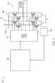
- FIG 1 shows an example of a schematic block wiring diagram of a circuit arrangement 10 for an electric motor, such as a stepper motor.
- the circuit arrangement 10 shows a stepper motor 12 controlled by a controller 18.
- the stepper motor 12 is controlled with a motor driver circuit 14, for example a voltage chopper.
- the motor driver circuit 14 generates a drive voltage for each coil of the stepper motor 12, for example the drive voltage may be a pulse width modulation (PWM) voltage for operating the stepper motor 12.
- PWM pulse width modulation
- a two-phase stepper motor 12 it may be assumed that one of the two coils (e.g., coil x) is subjected to a sinusoidal current course and the other coil (e.g., coil y) is supplied with a current course which is phase-shifted by 90° and thus co-sinusoidal.
- the stepper motor 12 may also be controlled in micro-step operation with a PWM voltage which results in a substantially sinusoidal motor coil current within the coils x, y.
- non-sinusoidal motor coil current stepper motors with the same or a different number of phases; an associated phase shift of the motor coil currents relative to one another which is not 90°; and/or a stepper motor operated in a full-, a half-, or a micro-step operation.
- a PWM voltage may be generated from a motor supply voltage, such that the amplitude of the motor supply voltage defines the amplitude of the PWM voltage.
- the motor supply voltage can be pulse-width-modulated and applied with corresponding polarity to the motor coils x, y.
- the duty factor of this modulation being controlled or regulated in such a way that the resulting effective voltage across the motor coils each has an amount which causes an instantaneous motor coil current value to flow.
- other methods may be used to cause the instantaneous target motor coil currents to flow.
- the control of the PWM may be based on a voltage-based control signal using known methods.
- the circuit arrangement 10 comprises, as components known per se, an integrated motor driver circuit 14, with which via outputs, first and second bridge circuits 16a, 16b are controlled.
- the bridge circuits 16 are arranged between a supply voltage +VM and ground.
- a first PWM voltage signal is applied to the coil x and a second PWM voltage signal is applied to the coil y.
- the motor driver circuit 14 receives a voltage or current-based control signal in order to control the amplitude or the amount of the voltage applied to each coil, or the duty factor of the PWM voltages, e.g. via a controller 18. Since these motor driver circuit 14 units are known per se, they do not need to be described in more detail.
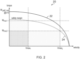
- Figure 2 shows a representation of an open loop operating mode on a graph 20.
- the velocity of the stepper motor is shown on the x-axis, and the torque of the stepper motor is shown on the y-axis.
- the graph 20 shows a line 22 representing the maximum power output of the stepper motor 12.
- the line 22 also represents the limitation in electrical power and the dependency of the mechanical power on the velocity in combination with the external applied force. Thus, there is a trade-off between the maximum allowed velocity and the maximum allowed torque. If the stepper motor 12 is operated to exceed the line 22 then motor stall will occur. All stepper motors may be characterised such that the line 22 represents the maximum power output of any stepper motor and can be determined (e.g., through experimentation) or may be generally readily available (e.g., from datasheets).
- the purpose of the safety margin line 24 is to set an artificial limit to the drive operation of the stepper motor 12 so that if a transient increase in the mechanical load is provided to the stepper motor, then torque can increase beyond the safety margin line 24, but within the line 22, temporarily without motor stall. This reduces the risk of motor stall, however, this also reduces the power handling of the stepper motor 12 because it is not being operated near its maximum power. This leads to system designers over dimensioning stepper motors for certain applications, and in particular maintaining a large torque safety margin at low velocities.
- the graph 20 shows how a high torque requirement M max 1 limits the maximum allowed velocity to V max 1 .
- the high velocity requirement of V max 2 limits the maximum allowed torque to M max 2 .
- a problem with a known operating mode is that if a control system is operated to target a specific velocity and a load on the stepper motor is increased, then to maintain the target velocity the torque on the stepper motor must increase.
- the combination of velocity and torque may require more power than the driver circuit can provide (or the stepper motor is rated for) which may result in motor stall, also called step loss.
- known closed loop systems may be implemented which use encoders to detect the position of the rotor of the stepper motor 12. Such systems may remove the need for a safety margin and operate a stepper motor close to the line 22. However, such systems require significantly higher design effort, die space, and cost to implement. Moreover, encoders may not be suitable for all applications and may require additional calibrations.
- Figure 3 shows a circuit arrangement 28 according to an example of the invention.
- the circuit arrangement 28 of Figure 3 is similar to the circuit arrangement 10 of Figure 1 and for brevity the following description will focus on the differences and like parts have been given the same reference numerals.
- the circuit arrangement 28 operates the stepper motor 12 in a control loop.
- the control loop may be implemented with, for example, a hysteresis controller or a PI regulator.
- a controller 26 receives a feedback signal from the stepper motor 12, e.g., a coil current (for one or more motor coils of the stepper motor 12), and/or a sensor measurement from an encoder, etc., via a feedback means 25.
- the controller 26 may receive a measurement of the actual motor coil current to regulate a duty factor of the PWM voltage applied to the respective motor coil via a control loop (that is, a voltage-based operating mode with a control loop).
- the actual motor coil current can be detected by the feedback means 25, for example, by means of an analog-to-digital converter (ADC) in order to control the amplitude or the amount of the voltage applied to the coil, or the duty factor of the PWM voltage, e.g. via a regulator, preferably a PI-regulator.
- the circuit arrangement 28 may operate in a current-based operating mode with a control loop.
- the ADC can sample the motor coil currents such that the load values comprise samples of a first motor coil current from the first stepper motor coil; and, samples of a second motor coil current from the second stepper motor coil.
- the motor driver circuit 14 may also receive as an input a coil current via the feedback means 25 to aid in operating the stepper motor 12.
- the controller 26 may be configured to implement a method which may output a signal suitable for operating the stepper motor 12 in accordance with examples of the invention.
- Figure 4a shows a simplified example of the actual motor coil currents I x , I y on each coil over a time period when the stepper motor is micro-stepped.
- the ADC 25 may sample the actual motor currents I x , I y to generate a first and second motor coil currents I ADC x , I ADC y respectively.
- Figure 4b shows a graphical representation of the first and second motor coil currents I ADCx , I ADC y on a graph with an x-axis representing the phase of the coil x, and a y-axis representing the phase of the coil y.
- the phase angle relationship between the first motor coil current I ADC x and the second motor coil current I ADC y is represented by the shape of a dashed circle 15.
- the phase angle relationship may be predetermined by the shape of the waveforms in Figure 4a and/or the phase angle between actual motor coil currents I x , I y . This may be predetermined via knowledge of the stepper motor 12 through known means per se. Therefore, the absolute value of the coil current vector
- can be determined by measuring the first and second motor coil currents I ADC x , I ADC y . Specifically, l I ADC x 2 + I ADC y 2 .
- the coil current phase angle ⁇ I can be determined between the coil current vector I and a pre-defined reference angle.
- the pre-defined reference angle may be 0 0 , or any other pre-determined angle.
- the coil current vector I is defined by the absolute value
- the coil current phase angle ⁇ I may be calculated based on the first and second motor coil currents I ADCx , I ADC y measurements using an ATAN2 function. It will be appreciated that the phase angle relationship between the first motor coil current I ADC x and the second motor coil current I ADC y shown is a result of micro-stepping (i.e., the controller 26 generates or receives a micro-step sequencer signal for operating the stepper motor).
- Current probes may be in series with a respective coil x, y (i.e., at the connection of the first and second bridge circuits 16a, 16b to the coils x, y). Additionally or alternatively, the motor coil currents I x , I y flowing through the coils x, y may be measured by probes at the base point (e.g., source of a bridge MOSFET) of the bridge circuit 16. The current probes may be coupled to the ADC 25 to measure the first and second motor coil currents I ADC x , I ADC y .
- the load value (e.g., load angle, load reserve, or any representation of the torque load) may be (directly, inversely, or indirectly) proportional to a mechanical load on the rotor of the stepper motor 12, such that if the rotor requires more torque to rotate at a given velocity, then the load value will increase.
- the load value may be a motor coil current or a load angle of the stepper motor 12.
- the load value therefore has a maximum load value L max which may be equivalent to the maximum power output of the stepper motor 12 (i.e., a stall load value: a load value which results in motor stall of the stepper motor 12), or a safety margin (reduced in comparison to Figure 2 ).
- Each load value may be proportional to a load angle of the stepper motor, or could be proportional to an encoder signal.
- the direction of the rotor is defined by its magnetization. If there is no mechanical load, the angle of the rotor corresponds to the main direction of the magnetic field that is generated by the coils-this corresponds to a load angle of 0°. If the direction of the magnetization of the rotor in a two-pole motor is orthogonal to the main direction of the magnetic field that is generated by the coils, then this corresponds to a load angle of 90°.
- the load angle when the motor is at a standstill, corresponds directly to the mechanical deflection by the neutral position on the motor shaft caused directly prior to the torque (without load and with a load angle of 0°).
- the load angle is an integral multiple of this mechanical deflection by the neutral position. In high pole-count motors the determination of the load angle therefore would require very high resolution rotary pulse generators and very precise current measurements.
- the load angle calculation may determine a load reserve ⁇ .
- the determination of the mechanical motor load may be represented by the load angle based on the voltage that is counter-induced in the motor coils by the rotation of the rotor (Back-electromotive force, Back-EMF, or counter-electromotive force, CEMF) and especially on the amount of this Back-EMF, which is position controlled in order to achieve a specified current flow in the respective stepper motor coil.
- the Back-EMF voltage angle may be further calculated based on any of: the supply voltage + V M ; the resistance R of the stepper motor coil x; the resistance R of the stepper motor coil y; and the inductance L of the stepper motor coil x; the inductance L of the stepper motor coil y.
- a stepper motor coil x, y may be typically modeled as a voltage source (in opposition to the coil driving voltage (e.g., PWM voltage signals) and a resistor.
- the supply voltage may correspond to the amplitude/scaling of PWM voltage signals, which can improve the calculation of the Back-EMF voltage angle.
- a stepper motor coil may be modeled as a voltage source (in opposition to the coil driving voltage), a resistor, and an inductor.
- the controller 26 enables a load angle of the stepper motor 12 to be detected in a sensor-free manner.
- a load angle may be calculated based on the absolute value
- the controller 26 receives load values associated with a mechanical load of the operating stepper motor. That is, the load values may be based on a mechanical load of the operating stepper motor. At relatively high velocities, the load values may provide a good indicator of the stall condition of the stepper motor. However, at low motor velocities (such as less than 10, less than 30 RPM, or less than 60 RPM) the received load values can be compromised by parasitic effects. The low motor velocity at which the received load values can be compromised by parasitic effects depends on (and can be determined based on) the motor characteristics and change in motor temperature, although in practice the disclosed method may be particularly beneficial if stall detection is required at velocities which are likely to approach said low motor velocities.
- load angle calculation schemes all generally function poorly at low motor velocities and provide a poor indicator of motor stall.
- the Back-EMF signal is very weak compared to each coil's voltage drop (e.g., due to resistance) which makes the calculation of the load angle unreliable.
- the load angle calculation may vary due to temperature related coil resistance, BBM delays, measurement errors, and to parasitic effects. For this reason, at low motor velocities it is difficult for a stepper motor controller to detect motor stall.
- a low motor velocity (at which the received load values can be compromised by parasitic effects) may be determined if the motor Back-EMF voltage is lower than the resistive voltage drop in a motor coil caused by coil current.
- the disclosed method is designed to extend this limit to at least velocities 4 to 10 times lower than standard techniques. It uses a floating mean value (generated by a moving average calculation) of the sensorless load value to get a much more stable and noise-free read out and reacts to a change in the load value corresponding to hitting a mechanical obstacle, rather than to an absolute load. This makes it insensitive to slow changes like thermal heat up of the motor coils leading to increased coil resistance.
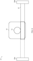
- Figure 5 shows an example of a system 21 comprising a stepper motor 12 with a rotor 13 (of the stepper motor) coupled to a linear actuator 27.
- the linear actuator 27 is limited by endpoints 29a, 29b such that the first endpoint 29b mechanically limits the rotation of the stepper motor 12 when the linear actuator 27 reaches the first endpoint 29b.
- the stepper motor 12 is coupled to the controller 26 to implement any method disclosed herein.
- the disclosed method is particularly useful when applied to a stepper motor coupled to a system with at least a first [pre-defined] endpoint which mechanically limits the rotation of the stepper motor when a component of the system reaches the first endpoint.
- a component of the system e.g., a linear actuation system.
- the mechanical endpoints of the stepper motors rotor are typically detected with distinct switches at either end of the system.
- the current system enables detection of the mechanical endpoints (of the stepper motors rotor) to be achieved without additional components.
- Figure 6 shows an exemplary method of the present disclosure implemented by the controller 26.
- Step S7 upon determining that the stepper motor is in the stall condition, the controller 26 may be configured to stop and reverse the stepper motor (i.e., move back a bit) to a position after which the torque initially started increasing. That is, to a position where the step value exceeded the predetermined threshold.
- this may allow for the removal of strain from the stepper motor and any associated mechanical apparatus.
- the controller 26 of the stepper motor 12 may determine that the method should be implemented if the controller 26 detects (or commands that) the stepper motor 12 is operating at a low velocity. Alternatively, the controller 26 of the stepper motor 12 may determine that the method should be implemented if the controller 26: determines the absolute value of the Back-EMF of the stepper motor 12; and compares the absolute value of the Back-EMF (as determined from a motor Back-EMF constant multiplied by the commanded operating velocity) to the absolute value of the temperature dependent change of resistive voltage drop in the motor coils (as determined by coil resistance change multiplied by motor current. Coil resistance change can be determined by expected motor temperature change during operation multiplied by the specific temperature coefficient (i.e. 0.038/K for copper). If the voltage drop due to effect of resistance change is significant (e.g., more than 10% of Back-EMF), then the method described herein may be beneficially used.
- Figure 7 shows a graph with a load value amplitude on the y-axis (specifically, a load reserve ⁇ ), by time on the x-axis (i.e., t).
- the graph of Figure 7 represents operational data from the stepper motor 12.
- the load values received or calculated by the controller 26 are shown by line 30, and are associated with the mechanical loads detected (that is, experienced) by the operating stepper motor over time.
- the load values are shown as a continuous line 30, however, the load values may be discretely calculated or determined.
- Stall detection values are shown by lines 32a, 32b.
- Line 32a shows the step value change between consecutive stall detection values.
- Line 32b shows the gradient between consecutive stall detection values.
- Stall detection values are determined by filtering the load values (or a sampled version of line 30 generated from the load values), that is, lines 32a, 32b are a filtered representation of line 30.
- Figure 7 shows captured experimental data of an operating stepper motor 12.
- the stepper motor 12 is operating at a low velocity.
- the mechanical load of the operating stepper motor 12 increases.
- the stepper motor 12 experiences a sudden mechanical load increase due to a sudden blocking of the rotor, or due to a mechanical limit of the rotor being reached. It can be seen from Figure 7 , that this causes a change between two stall detection values at point (t1) and point (t2), and also a change between two stall detection values at point (t2) and point (t3).
- the sudden mechanical load increase causes a change in consecutive and/or subsequent stall detection values. This change in subsequent stall detection values can be quantified as a step value. If the step value is greater than a predetermined threshold, then this indicates a stall event.
- the cause of the increased mechanical load is overcome, and the stepper motor 12 may be operated under normal conditions.
- a stepper motor stall condition may be detected from a change between only two stall detection values, or may detected from a change over multiple stall detection values. That is, the change (i.e., the step value) is compared to a predetermined threshold to determine that the stepper motor 12 is in a stall condition.
- the predetermined threshold may be an absolute value, or it may represent a rate of change (i.e., a gradient) of the stall detection values and/or line 32b.
- a rate of change of the stall detection values may be used to determine that the stepper motor is in a stall condition.
- the steepness of the gradient of the line 32b connecting the stall detection values correlates to more mechanical resistance on the stepper motor rotor. Therefore, the rate of change in the stall detection values may be compared to a predetermined threshold to determine if the stepper motor is in a stall condition.
- the predetermined threshold may be pre-determined based on the application of the stepper motor, and/or found via stepper motor experimentation.
- the stall condition may signal that the stepper motor has stalled, or that the stepper motor is at risk of stalling (i.e., if the mechanical load increases further, then the stepper motor will stall).
- the predetermined threshold may be an absolute value, for example, if the change between two stall detection values occurs over a known time period between the two stall detection values. For example, depending on the filtering type the time period may be determined or estimated based on the sampling rate of the load values.
- the step value may be determined from consecutive stall detection values, or the step value may be determined from any two stall detection values with a known time period between them. Therefore, determining that the step value is based on the difference between two stall detection values can comprise determining the rate of change in the stall detection values.
- comparing the step value to the predetermined threshold may comprise comparing the rate of change in the stall detection values to the threshold, wherein the predetermined threshold is a rate of change threshold.
- the method may be unaffected by non-load dependent operational conditions of the stepper motor 12. For example, the stepper motor temperature or thermal heat up of the stepper motor.
- Figure 8 shows a graph with a load value amplitude on the y-axis (specifically, a load reserve ⁇ determined from motor coil currents), by time on the x-axis (i.e., t).
- the graph of Figure 8 represents operational data from the stepper motor 12 which has a constant mechanical load. Over time, the temperature of the stepper motor 12 rises which affects the resistance of the stepper motor coils. Therefore, since the load value is a function of motor coil currents, then as the temperature increases overtime, the load reserve decreases. This change (and other non-load dependent operational conditions of the stepper motor 12) occurs over a relatively large time period, which may be neglected by setting the predetermined threshold to account for the time period between stall detection values and/or the rate of change of the stall detection values.
- Filtering the load values comprises averaging the load values, for example, with a moving average.
- the moving average averages a defined set of load values (i.e., a window).
- other methods of filtering may be used such as, smoothing, low pass filtering, etc.
- Figures 9a and 9b both show a graph with a load value amplitude on the y-axis (specifically, a load reserve ⁇ ), by time on the x-axis (i.e., t).
- the graph of Figures 9a, 9b represents operational data from the stepper motor 12 which has a constant mechanical load, and load values are averaged using a moving average with a window.
- Figure 9a filters the load values (to determine the stall detection values) by averaging the load values over 90 degrees of an electrical cycle of current in a motor coil of the stepper motor 12. That is, the window of the moving average is 90 degrees of an electrical cycle of current in a motor coil of the stepper motor 12.
- Figure 9a shows a repeating pattern of stall detection values, which each consist of four stall detection values before repeating. This effect has been found to occur as a result of the stepper motor manufacturing process.
- a benefit of selecting the window as 90 degrees of an electrical cycle of current in a motor coil of the stepper motor 12, is that the system may be able to react quickly to a possible stall condition.
- the filtered signal i.e., stall detection values
- the effect of a repeating pattern of stall detection values may be reduced or eliminated by decreasing component tolerances of the stepper motor, or as shown in Figure 9b , by averaging the load values over one electrical cycle of current in a motor coil of the stepper motor. That is, in Figure 9b , the window of the moving average is a whole electrical cycle of current in a motor coil of the stepper motor 12.
- the stability of the stall detection method is improved by averaging the load values over one electrical cycle of current in a motor coil of the stepper motor.
- the stall detection values would not necessarily reach maximum load (0 load reserve), when the motor becomes overloaded (i.e., the stepper motor is in a stall condition), as the motor might stall before the filter has covered a full electrical period. Theoretically, a sudden stop of the rotor starting with 0-load will lead to a step loss in 1 ⁇ 2 electrical period. Practically, limited mechanical stiffness of the stepper motor system will lead to a non-instantaneous and longer period where load increases, until the motor stalls. The stall detection values would thus result in at least two consecutive step value decreases. This result may enable the system to determine that the stepper motor 12 is in a stall condition.
- the window of the moving average may be any fraction of the electrical cycle of current in a motor coil of the stepper motor or rotation. However, it should be taken into account that measurement noise may only be cancelled out by filtering over somewhat higher periods (i.e., greater than 45 degrees of an electrical cycle), as shown herein.
- the predetermined threshold may be adapted to represent an absolute value between the stall detection values when the stepper motor 12 is determined to be running without a mechanical load.
- the predetermined threshold may be adapted to represent the gradient between the stall detection values when the stepper motor 12 is determined to be running with a mechanical load. Therefore, the predetermined threshold may be predetermined: before the stepper motor is operated; based on a determination that the stepper motor is operating with a mechanical load; or based on a determination that the stepper motor is operating in one of many operating scenarios.
- the time period between consecutive stall detection values may be calculated based on a known load value sampling rate.
- the length of the moving average window as a ratio of an electrical cycle may be determined based on the known load value sampling rate or the time period.
- the change in subsequent stall detection values is a decrease.
- the load values represent the load angle
- the change in subsequent stall detection values is an increase.
- the load values represent the mechanical torque
- the change in subsequent stall detection values is an increase. That is, the change, either an increase or decrease, between subsequent stall detection values depends on the particular load values received.
- a stepper motor stall condition may be detected from a change over multiple stall detection values. For example, returning to Figure 7 , a first step value may be determined based on the difference between the first stall detection value at point (t1), and the second stall detection value at point (t2), and a second step value may be determined based on the difference between the second stall detection value at point (t2) and a third stall detection value at point (t3).
- a combination of the first and second step values may be compared to the predetermined threshold (for example, the combination may be an average of any type: mean, weighted, etc.). The method may determine that the stepper motor is in a stall condition based on the comparison between the combination of the first and second step values to the predetermined threshold.
- the first step value may be compared to a first predetermined threshold
- the second step value may be compared to a second predetermined threshold, and only if both the first and second predetermined thresholds are exceeded is a stall condition detected.
- the first and second predetermined thresholds may be equivalent.
- Clause 1 A method of operating a stepper motor, the method comprising:
- Clause 2 The method of clause 1, wherein filtering the load values comprises averaging the load values over at least 90 degrees of an electrical cycle of current in a motor coil of the stepper motor.
- Clause 3 The method of any of clauses 1 or 2, wherein filtering the load values comprises averaging the load values over one electrical cycle of current in a motor coil of the stepper motor.
- comparing the step value to the predetermined threshold comprises comparing the rate of change in the stall detection values to the predetermined threshold, wherein the predetermined threshold is a rate of change threshold.
- Clause 5 The method of any preceding clause, wherein load values are received by: sampling a first motor coil current from the first motor coil; and sampling a second motor coil current from the second motor coil.
- Clause 7 The method of any preceding clause, wherein the load values are associated with the mechanical loads detected by the operating stepper motor.
- Clause 8 The method of any preceding clause, wherein filtering the load values comprises averaging the load values.
- Clause 9 The method of any preceding clause, wherein determining the step value is further based on the difference between two consecutive stall detection values.
- Clause 10 The method of any preceding clause, further comprising stopping the stepper motor in response to determining that the stepper motor is in a stall condition.
- Clause 11 The method of any preceding clause, wherein determining that the step value is based on the difference between two stall detection values comprises determining the rate of change in the stall detection values.
- Clause 12 The method of any preceding clause, wherein the two stall detection values are a first and second stall detection values, and the step value is a first step value;
- Clause 13 The method of any of clauses 1 to 11, wherein the two stall detection values are a first and second stall detection values, the predetermined threshold is a first predetermined threshold, and the step value is a first step value;
- Clause 14 The method of any preceding clause, wherein operating the stepper motor in a control loop comprises operating the stepper motor at less than: 60, 30, 20 or 10 revolutions per minute.
- a circuit arrangement for operating a stepper motor in a control loop comprising: a controller, configured to: operate the stepper motor at a velocity:
- Clause 16 The circuit arrangement of clause 15, wherein the controller is further configured to stop the stepper motor in response to determining that the stepper motor is in a stall condition.
- Clause 17 The circuit arrangement of any of clauses 15 or 16, wherein filtering the load values comprises averaging the load values over at least 90 degrees of an electrical cycle of current in a motor coil of the stepper motor.
- Clause 18 The circuit arrangement of any of clauses 15 to 17, wherein filtering the load values comprises averaging the load values over one electrical cycle of current in a motor coil of the stepper motor.
- Clause 19 The circuit arrangement of any of clauses 15 to 18, wherein comparing the step value to the predetermined threshold comprises comparing the rate of change in the stall detection values to the predetermined threshold, wherein the predetermined threshold is a rate of change threshold.
- Clause 20 The circuit arrangement of any of clauses 15 to 19, the circuit arrangement configured to:
- each block of Figure 1 and Figure 3 is shown and defined for explanatory purposes only, it would be well understood that the algorithm or function which each block represents may be implemented in a plurality of other ways so long as the functionality as described is present.
- the blocks of Figure 1 and/or 3 may be combined and implemented as part of a circuit arrangement, on a single integrated circuit, processor, or computer, or implemented by a plurality of circuit arrangements, integrated circuits, processors, and/or computers. That is, the controller comprises one or more circuit arrangements, integrated circuits, processors, and/or computers.
Landscapes
- Engineering & Computer Science (AREA)
- Power Engineering (AREA)
- Physics & Mathematics (AREA)
- General Physics & Mathematics (AREA)
- Control Of Stepping Motors (AREA)
Applications Claiming Priority (1)
| Application Number | Priority Date | Filing Date | Title |
|---|---|---|---|
| US18/358,568 US12549117B2 (en) | 2023-07-25 | 2023-07-25 | Stepper motor stall detection |
Publications (1)
| Publication Number | Publication Date |
|---|---|
| EP4498596A1 true EP4498596A1 (de) | 2025-01-29 |
Family
ID=90826426
Family Applications (1)
| Application Number | Title | Priority Date | Filing Date |
|---|---|---|---|
| EP24171610.9A Pending EP4498596A1 (de) | 2023-07-25 | 2024-04-22 | Stillstandserkennung eines schrittmotors |
Country Status (3)
| Country | Link |
|---|---|
| US (1) | US12549117B2 (de) |
| EP (1) | EP4498596A1 (de) |
| CN (1) | CN119382550A (de) |
Citations (3)
| Publication number | Priority date | Publication date | Assignee | Title |
|---|---|---|---|---|
| EP2966772A1 (de) * | 2014-07-11 | 2016-01-13 | Melexis Technologies NV | Verfahren und elektronische schaltung für motorstillstandserkennung |
| EP3261245A1 (de) * | 2016-06-22 | 2017-12-27 | Melexis Technologies NV | Verfahren und elektronische schaltung zur stillstandserkennung |
| US10153718B2 (en) * | 2017-02-17 | 2018-12-11 | Stmicroelectronics, Inc. | Stepper motor drive and stall detection circuit |
Family Cites Families (7)
| Publication number | Priority date | Publication date | Assignee | Title |
|---|---|---|---|---|
| DE102009040139B4 (de) | 2009-09-05 | 2012-10-04 | Trinamic Motion Control Gmbh & Co. Kg | Verfahren und Schaltungsanordnung zur sensorlosen Motorlasterfassung und zur lastwertabhängigen Motorstromregelung bei Schrittmotoren |
| DE102009053564B4 (de) | 2009-11-18 | 2020-03-19 | Trinamic Motion Control Gmbh & Co. Kg | Verfahren und Schaltungsanordnung zur Stromregelung bei Motoren |
| US9112439B2 (en) | 2010-11-09 | 2015-08-18 | Trinamic Motion Control Gmbh & Co. Kg | Method and circuit arrangement for detecting motor load without sensors and for controlling motor current according to load for a stepper motor |
| DE102014108637A1 (de) | 2014-06-18 | 2015-12-24 | Trinamic Motion Control Gmbh & Co. Kg | Verfahren und Schaltungsanordnung zum Ansteuern eines Schrittmotors |
| DE102017118837A1 (de) | 2017-08-17 | 2019-02-21 | Trinamic Motion Control Gmbh & Co. Kg | Verfahren und Schaltungsanordnung zur Resonanzdämpfung bei Schrittmotoren |
| DE102018126954A1 (de) | 2018-10-29 | 2020-04-30 | Trinamic Motion Control Gmbh & Co. Kg | Verfahren und Schaltungsanordnung zur sensorlosen Lasterfassung bei Schrittmotoren |
| US12316266B2 (en) * | 2023-05-31 | 2025-05-27 | Texas Instruments Incorporated | Methods and apparatus to detect a stall of a stepper motor |
-
2023
- 2023-07-25 US US18/358,568 patent/US12549117B2/en active Active
-
2024
- 2024-04-22 EP EP24171610.9A patent/EP4498596A1/de active Pending
- 2024-04-23 CN CN202410490505.4A patent/CN119382550A/zh active Pending
Patent Citations (3)
| Publication number | Priority date | Publication date | Assignee | Title |
|---|---|---|---|---|
| EP2966772A1 (de) * | 2014-07-11 | 2016-01-13 | Melexis Technologies NV | Verfahren und elektronische schaltung für motorstillstandserkennung |
| EP3261245A1 (de) * | 2016-06-22 | 2017-12-27 | Melexis Technologies NV | Verfahren und elektronische schaltung zur stillstandserkennung |
| US10153718B2 (en) * | 2017-02-17 | 2018-12-11 | Stmicroelectronics, Inc. | Stepper motor drive and stall detection circuit |
Also Published As
| Publication number | Publication date |
|---|---|
| US12549117B2 (en) | 2026-02-10 |
| CN119382550A (zh) | 2025-01-28 |
| US20250038684A1 (en) | 2025-01-30 |
Similar Documents
| Publication | Publication Date | Title |
|---|---|---|
| JP5411428B2 (ja) | 電気モータのための制御回路、電気モータの角度位置を決定し、電気モータの回転方向を決定するための方法 | |
| TWI463788B (zh) | 用於檢測失步情況的方法 | |
| US6738718B2 (en) | Method and apparatus for measuring torque and flux current in a synchronous motor | |
| EP3261245B1 (de) | Verfahren und elektronische schaltung zur stillstandserkennung | |
| WO2012046410A1 (ja) | Pmモータの電流制御ゲイン調整方法、電流制御方法および制御装置 | |
| KR101448677B1 (ko) | Bldc 모터의 회전자 위치 추정 장치 및 방법 | |
| US11101754B2 (en) | Stall detection in stepper motors using differential back-EMF between rising and falling commutation phase of motor current | |
| JP5078676B2 (ja) | ステッピングモータ駆動制御装置及びステッピングモータ駆動制御方法 | |
| EP4498596A1 (de) | Stillstandserkennung eines schrittmotors | |
| US12255558B2 (en) | Motor controller, motor system and method for controlling motor | |
| JP5464793B2 (ja) | モータ駆動装置 | |
| EP1575158B1 (de) | Positionsbestimmung des Rotors eines bürstenlosen Gleichstrommotors | |
| EP1806835B1 (de) | Motorantriebsvorrichtung | |
| US20220385216A1 (en) | Motor drive control device, motor unit, and motor drive control method | |
| EP3244528B1 (de) | Leistungswandler und steuerungsverfahren für leistungswandler | |
| JP4470445B2 (ja) | モータケーブル抵抗検出方法およびその装置 | |
| JP3797484B2 (ja) | ステッピングモータの駆動装置 | |
| JP7294917B2 (ja) | ステッピングモータ制御装置、ステッピングモータ制御方法 | |
| US12261565B2 (en) | Electric motor control system | |
| JP7763096B2 (ja) | モータ駆動制御装置 | |
| CN119790589A (zh) | 用于不具有位置传感器的多相无刷马达的控制系统 | |
| JP2022037441A (ja) | 制御装置および電動アクチュエータ |
Legal Events
| Date | Code | Title | Description |
|---|---|---|---|
| PUAI | Public reference made under article 153(3) epc to a published international application that has entered the european phase |
Free format text: ORIGINAL CODE: 0009012 |
|
| STAA | Information on the status of an ep patent application or granted ep patent |
Free format text: STATUS: REQUEST FOR EXAMINATION WAS MADE |
|
| 17P | Request for examination filed |
Effective date: 20240422 |
|
| AK | Designated contracting states |
Kind code of ref document: A1 Designated state(s): AL AT BE BG CH CY CZ DE DK EE ES FI FR GB GR HR HU IE IS IT LI LT LU LV MC ME MK MT NL NO PL PT RO RS SE SI SK SM TR |