EP4498564A1 - Vorrichtung und verfahren zur bestimmung der quellenkapazität zum laden einer elektronischen vorrichtung - Google Patents
Vorrichtung und verfahren zur bestimmung der quellenkapazität zum laden einer elektronischen vorrichtung Download PDFInfo
- Publication number
- EP4498564A1 EP4498564A1 EP23850281.9A EP23850281A EP4498564A1 EP 4498564 A1 EP4498564 A1 EP 4498564A1 EP 23850281 A EP23850281 A EP 23850281A EP 4498564 A1 EP4498564 A1 EP 4498564A1
- Authority
- EP
- European Patent Office
- Prior art keywords
- source capability
- electronic device
- charger
- charging
- capability message
- Prior art date
- Legal status (The legal status is an assumption and is not a legal conclusion. Google has not performed a legal analysis and makes no representation as to the accuracy of the status listed.)
- Pending
Links
Images
Classifications
-
- H—ELECTRICITY
- H02—GENERATION; CONVERSION OR DISTRIBUTION OF ELECTRIC POWER
- H02J—ELECTRIC POWER NETWORKS; CIRCUIT ARRANGEMENTS OR SYSTEMS FOR SUPPLYING OR DISTRIBUTING ELECTRIC POWER; SYSTEMS FOR STORING ELECTRIC ENERGY
- H02J7/00—Circuit arrangements for charging or discharging batteries or for supplying loads from batteries
- H02J7/40—Circuit arrangements for charging or discharging batteries or for supplying loads from batteries characterised by the exchange of charge or discharge related data
- H02J7/47—Arrangements for checking compatibility or authentication between one component, e.g. a battery or a battery charger, and another component, e.g. a power source
-
- G—PHYSICS
- G06—COMPUTING OR CALCULATING; COUNTING
- G06F—ELECTRIC DIGITAL DATA PROCESSING
- G06F1/00—Details not covered by groups G06F3/00 - G06F13/00 and G06F21/00
- G06F1/26—Power supply means, e.g. regulation thereof
-
- G—PHYSICS
- G06—COMPUTING OR CALCULATING; COUNTING
- G06F—ELECTRIC DIGITAL DATA PROCESSING
- G06F3/00—Input arrangements for transferring data to be processed into a form capable of being handled by the computer; Output arrangements for transferring data from processing unit to output unit, e.g. interface arrangements
- G06F3/06—Digital input from, or digital output to, record carriers, e.g. RAID, emulated record carriers or networked record carriers
- G06F3/0601—Interfaces specially adapted for storage systems
- G06F3/0628—Interfaces specially adapted for storage systems making use of a particular technique
- G06F3/0655—Vertical data movement, i.e. input-output transfer; data movement between one or more hosts and one or more storage devices
- G06F3/0658—Controller construction arrangements
-
- G—PHYSICS
- G06—COMPUTING OR CALCULATING; COUNTING
- G06F—ELECTRIC DIGITAL DATA PROCESSING
- G06F3/00—Input arrangements for transferring data to be processed into a form capable of being handled by the computer; Output arrangements for transferring data from processing unit to output unit, e.g. interface arrangements
- G06F3/06—Digital input from, or digital output to, record carriers, e.g. RAID, emulated record carriers or networked record carriers
- G06F3/0601—Interfaces specially adapted for storage systems
- G06F3/0628—Interfaces specially adapted for storage systems making use of a particular technique
- G06F3/0655—Vertical data movement, i.e. input-output transfer; data movement between one or more hosts and one or more storage devices
- G06F3/0659—Command handling arrangements, e.g. command buffers, queues, command scheduling
-
- H—ELECTRICITY
- H02—GENERATION; CONVERSION OR DISTRIBUTION OF ELECTRIC POWER
- H02J—ELECTRIC POWER NETWORKS; CIRCUIT ARRANGEMENTS OR SYSTEMS FOR SUPPLYING OR DISTRIBUTING ELECTRIC POWER; SYSTEMS FOR STORING ELECTRIC ENERGY
- H02J7/00—Circuit arrangements for charging or discharging batteries or for supplying loads from batteries
- H02J7/40—Circuit arrangements for charging or discharging batteries or for supplying loads from batteries characterised by the exchange of charge or discharge related data
- H02J7/42—Circuit arrangements for charging or discharging batteries or for supplying loads from batteries characterised by the exchange of charge or discharge related data with electronic devices having internal batteries, e.g. mobile phones
-
- H—ELECTRICITY
- H02—GENERATION; CONVERSION OR DISTRIBUTION OF ELECTRIC POWER
- H02J—ELECTRIC POWER NETWORKS; CIRCUIT ARRANGEMENTS OR SYSTEMS FOR SUPPLYING OR DISTRIBUTING ELECTRIC POWER; SYSTEMS FOR STORING ELECTRIC ENERGY
- H02J7/00—Circuit arrangements for charging or discharging batteries or for supplying loads from batteries
- H02J7/90—Regulation of charging or discharging current or voltage
- H02J7/933—Regulation of charging or discharging current or voltage the cycle being controlled or terminated in response to electric parameters
Definitions
- the disclosure relates to a method of displaying a screen of an application executed by using at least one of pieces of subscriber identification module information read by an electronic device.
- USB universal serial bus
- USB power delivery (PD).
- Embodiments of the disclosure may provide the determining of whether charging is available based on a received source capability message, the determining of a target source capability, and the instructing of a charger to transmit power through the target source capability.
- an electronic device includes a memory configured to store computer-executable instructions and a processor configured to execute the instructions by accessing the memory, in which, when executed by the processor, the instructions cause the electronic device to receive a source capability message of a charger from the charger, determine whether charging is available based on the received source capability message, in response to charging being unavailable based on the received source capability message, instruct the charger to retransmit a source capability message, and, based on the number of determining that charging is unavailable based on the source capability message received from the charger, exclude the source capability message and instruct the charger to transmit power through a predetermined source capability.
- an operating method, implemented by a processor, of an electronic device includes receiving a source capability message of a charger from the charger, determining whether charging is available based on the received source capability message, in response to charging being unavailable based on the received source capability message, instructing the charger to retransmit a source capability message, and, based on the number of determining that charging is unavailable based on the source capability message received from the charger, excluding the source capability message and instructing the charger to transmit power through a predetermined source capability.
- Embodiments of the disclosure may determine whether charging is available based on a received source capability message, determine a target source capability, and instruct a charger to transmit power through the target source capability.
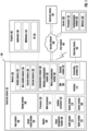
- FIG. 1 is a block diagram illustrating an electronic device 101 in a network environment 100, according to various embodiments.
- the electronic device 101 in the network environment 100 may communicate with an electronic device 102 via a first network 198 (e.g., a short-range wireless communication network), or communicate with at least one of an electronic device 104 or a server 108 via a second network 199 (e.g., a long-range wireless communication network).
- the electronic device 101 may communicate with the electronic device 104 via the server 108.
- the electronic device 101 may include a processor 120, a memory 130, an input module 150, a sound output module 155, a display module 160, an audio module 170, and a sensor module 176, an interface 177, a connecting terminal 178, a haptic module 179, a camera module 180, a power management module 188, a battery 189, a communication module 190, a subscriber identification module (SIM) 196, or an antenna module 197.
- at least one of the components e.g., the connecting terminal 178) may be omitted from the electronic device 101, or one or more other components may be added in the electronic device 101.
- some of the components e.g., the sensor module 176, the camera module 180, or the antenna module 197) may be integrated as a single component (e.g., the display module 160).
- the processor 120 may execute, for example, software (e.g., a program 140) to control at least one other component (e.g., a hardware or software component) of the electronic device 101 connected to the processor 120 and may perform various data processing or computation.
- the processor 120 may store a command or data received from another component (e.g., the sensor module 176 or the communication module 190) in a volatile memory 132, process the command or the data stored in the volatile memory 132, and store resulting data in a non-volatile memory 134.
- the processor 120 may include a main processor 121 (e.g., a central processing unit (CPU) or an application processor (AP)), or an auxiliary processor 123 (e.g., a graphics processing unit (GPU), a neural processing unit (NPU), an image signal processor (ISP), a sensor hub processor, or a communication processor (CP)) that is operable independently from or in conjunction with the main processor 121.
- a main processor 121 e.g., a central processing unit (CPU) or an application processor (AP)
- auxiliary processor 123 e.g., a graphics processing unit (GPU), a neural processing unit (NPU), an image signal processor (ISP), a sensor hub processor, or a communication processor (CP)
- the auxiliary processor 123 may be adapted to consume less power than the main processor 121 or to be specific to a specified function.
- the assistance processor 123 may be implemented separately from the main processor 121 or as a part of the main processor 121.
- the auxiliary processor 123 may control at least some of functions or states related to at least one (e.g., the display module 160, the sensor module 176, or the communication module 190) of the components of the electronic device 101 instead of the main processor 121 while the main processor 121 is in an inactive (e.g., sleep) state or along with the main processor 121 while the main processor 121 is an active state (e.g., executing an application).
- the auxiliary processor 123 e.g., an ISP or a CP
- the auxiliary processor 123 may include a hardware structure specifically for artificial intelligence model processing.
- An artificial intelligence (AI) model may be generated by machine learning.
- the machine learning may be performed by, for example, the electronic device 101, in which artificial intelligence is performed, or performed via a separate server (e.g., the server 108).
- Learning algorithms may include, but are not limited to, for example, supervised learning, unsupervised learning, semi-supervised learning, or reinforcement learning.
- the AI model may include a plurality of artificial neural network layers.
- An artificial neural network may include, for example, a deep neural network (DNN), a convolutional neural network (CNN), a recurrent neural network (RNN), a restricted Boltzmann machine (RBM), a deep belief network (DBN), a bidirectional recurrent deep neural network (BRDNN), and a deep Q-network or a combination of two or more thereof but is not limited thereto.
- the AI model may additionally or alternatively include a software structure other than the hardware structure.
- the memory 130 may store various pieces of data used by at least one component (e.g., the processor 120 or the sensor module 176) of the electronic device 101.
- the various pieces of data may include, for example, software (e.g., the program 140) and input data or output data for a command related thereto.
- the memory 130 may include the volatile memory 132 or the non-volatile memory 134.
- the program 140 may be stored as software in the memory 130, and may include, for example, an operating system (OS) 142, middleware 144, or an application 146.
- OS operating system
- middleware middleware
- application application
- the input module 150 may receive a command or data to be used by another component (e.g., the processor 120) of the electronic device 101, from the outside (e.g., a user) of the electronic device 101.
- the input module 150 may include, for example, a microphone, a mouse, a keyboard, a key (e.g., a button), or a digital pen (e.g., a stylus pen).
- the sound output module 155 may output a sound signal to the outside of the electronic device 101.
- the sound output module 155 may include, for example, a speaker or a receiver.
- the speaker may be used for general purposes, such as playing multimedia or playing record.
- the receiver may be used to receive an incoming call. According to an embodiment, the receiver may be implemented separately from the speaker or as a portion of the speaker.
- the display module 160 may visually provide information to the outside (e.g., a user) of the electronic device 101.
- the display module 160 may include, for example, a display, a hologram device, or a projector and control circuitry to control a corresponding one of the display, the hologram device, and the projector.
- the display module 160 may include a touch sensor adapted to detect a touch, or a pressure sensor adapted to measure the intensity of force incurred by the touch.
- the audio module 170 may convert a sound into an electrical signal or vice versa. According to an embodiment, the audio module 170 may obtain the sound via the input module 150 or output the sound via the sound output module 155 or an external electronic device (e.g., the electronic device 102 such as a speaker or a headphone) directly or wirelessly connected to the electronic device 101.
- an external electronic device e.g., the electronic device 102 such as a speaker or a headphone
- the sensor module 176 may detect an operational state (e.g., power or temperature) of the electronic device 101 or an environmental state (e.g., a state of a user) external to the electronic device 101, and then generate an electrical signal or data value corresponding to the detected state.
- the sensor module 176 may include, for example, a gesture sensor, a gyro sensor, an atmospheric pressure sensor, a magnetic sensor, an acceleration sensor, a grip sensor, a proximity sensor, a color sensor, an infrared (IR) sensor, a biometric sensor, a temperature sensor, a humidity sensor, or an illuminance sensor.
- the interface 177 may support one or more specified protocols to be used for the electronic device 101 to be coupled with the external electronic device (e.g., the electronic device 102) directly (e.g., by wire) or wirelessly.
- the interface 177 may include, for example, a high-definition multimedia interface (HDMI), a universal serial bus (USB) interface, a secure digital (SD) card interface, or an audio interface.
- HDMI high-definition multimedia interface
- USB universal serial bus
- SD secure digital
- the connecting terminal 178 may include a connector via which the electronic device 101 may be physically connected with the external electronic device (e.g., the electronic device 102).
- the connecting terminal 178 may include, for example, an HDMI connector, a USB connector, an SD card connector, or an audio connector (e.g., a headphones connector).
- the haptic module 179 may convert an electric signal into a mechanical stimulus (e.g., a vibration or a movement) or an electrical stimulus, which may be recognized by a user via their tactile sensation or kinesthetic sensation.
- the haptic module 179 may include, for example, a motor, a piezoelectric element, or an electric stimulator.
- the camera module 180 may capture a still image and moving images.
- the camera module 180 may include one or more lenses, image sensors, image signal processors, or flashes.
- the power management module 188 may manage power supplied to the electronic device 101.
- the power management module 188 may be implemented as, for example, at least a part of a power management integrated circuit (PMIC).
- PMIC power management integrated circuit
- the battery 189 may supply power to at least one component of the electronic device 101.
- the battery 189 may include, for example, a primary cell, which is not rechargeable, a secondary cell, which is rechargeable, or a fuel cell.
- the communication module 190 may support establishing a direct (e.g., wired) communication channel or a wireless communication channel between the electronic device 101 and the external electronic device (e.g., the electronic device 102, the electronic device 104, or the server 108) and performing communication via the established communication channel.
- the communication module 190 may include one or more CPs that are operable independently from the processor 120 (e.g., an AP) and that support direct (e.g., wired) communication or wireless communication.
- the communication module 190 may include a wireless communication module 192 (e.g., a cellular communication module, a short-range wireless communication module, or a global navigation satellite system (GNSS) communication module) or a wired communication module 194 (e.g., a local area network (LAN) communication module, or a power line communication (PLC) module).
- a wireless communication module 192 e.g., a cellular communication module, a short-range wireless communication module, or a global navigation satellite system (GNSS) communication module
- GNSS global navigation satellite system
- wired communication module 194 e.g., a local area network (LAN) communication module, or a power line communication (PLC) module.
- LAN local area network
- PLC power line communication
- a corresponding one of these communication modules may communicate with the external electronic device 104 via the first network 198 (e.g., a short-range communication network, such as BluetoothTM, Wi-Fi direct, or infrared data association (IrDA)) or the second network 199 (e.g., a long-range communication network, such as a legacy cellular network, a 5G network, a next-generation communication network, the Internet, or a computer network (e.g., LAN or wide area network (WAN)).
- first network 198 e.g., a short-range communication network, such as BluetoothTM, Wi-Fi direct, or infrared data association (IrDA)
- the second network 199 e.g., a long-range communication network, such as a legacy cellular network, a 5G network, a next-generation communication network, the Internet, or a computer network (e.g., LAN or wide area network (WAN)
- These various types of communication modules may be implemented as a single component (e
- the wireless communication module 192 may identify and authenticate the electronic device 101 in a communication network, such as the first network 198 or the second network 199, using subscriber information (e.g., international mobile subscriber identity (IMSI)) stored in the SIM 196.
- subscriber information e.g., international mobile subscriber identity (IMSI)
- the communication module may establish communication with a target device (e.g., the electronic device 104) for mirroring display.
- the wireless communication module 192 may support a 5G network after a 4G network, and next-generation communication technology, e.g., new radio (NR) access technology.
- the NR access technology may support enhanced mobile broadband (eMBB), massive machine type communications (mMTC), or ultra-reliable and low-latency communications (URLLC).
- eMBB enhanced mobile broadband
- mMTC massive machine type communications
- URLLC ultra-reliable and low-latency communications
- the wireless communication module 192 may support a high-frequency band (e.g., a mmWave band) to achieve, e.g., a high data transmission rate.
- a high-frequency band e.g., a mmWave band
- the wireless communication module 192 may support various technologies for securing performance on a high-frequency band, such as, e.g., beamforming, massive multiple-input and multiple-output (MIMO), full dimensional MIMO (FD-MIMO), an array antenna, analog beamforming, or a large-scale antenna.
- MIMO massive multiple-input and multiple-output
- FD-MIMO full dimensional MIMO
- the wireless communication module 192 may support various requirements specified in the electronic device 101, an external electronic device (e.g., the electronic device 104), or a network system (e.g., the second network 199).
- the wireless communication module 192 may support a peak data rate (e.g., 20 Gbps or more) for implementing eMBB, loss coverage (e.g., 164 dB or less) for implementing mMTC, or U-plane latency (e.g., 0.5 ms or less for each of downlink (DL) and uplink (UL), or a round trip of 1 ms or less) for implementing URLLC.
- a peak data rate e.g., 20 Gbps or more
- loss coverage e.g., 164 dB or less
- U-plane latency e.g., 0.5 ms or less for each of downlink (DL) and uplink (UL), or a round trip of 1 ms or less
- the antenna module 197 may transmit or receive a signal or power to or from the outside (e.g., the external electronic device) of the electronic device 101.
- the antenna module 197 may include an antenna including a radiating element including a conductive material or a conductive pattern formed in or on a substrate (e.g., a printed circuit board (PCB)).
- the antenna module 197 may include a plurality of antennas (e.g., an antenna array). In such a case, at least one antenna appropriate for a communication scheme used in a communication network, such as the first network 198 or the second network 199, may be selected by, for example, the communication module 190 from the plurality of antennas.
- the signal or the power may be transmitted or received between the communication module 190 and the external electronic device via the at least one selected antenna.
- another component e.g., a radio frequency integrated circuit (RFIC)
- RFIC radio frequency integrated circuit
- the antenna module 197 may form a mmWave antenna module.
- the mm Wave antenna module may include a PCB, an RFIC disposed on a first surface (e.g., a bottom surface) of the PCB or adjacent to the first surface and capable of supporting a designated a high-frequency band (e.g., the mm Wave band), and a plurality of antennas (e.g., array antennas) disposed on a second surface (e.g., a top or a side surface) of the PCB, or adjacent to the second surface and capable of transmitting or receiving signals in the designated high-frequency band.
- At least some of the above-described components may be coupled mutually and communicate signals (e.g., commands or data) therebetween via an inter-peripheral communication scheme (e.g., a bus, general purpose input and output (GPIO), serial peripheral interface (SPI), or mobile industry processor interface (MIPI)).
- an inter-peripheral communication scheme e.g., a bus, general purpose input and output (GPIO), serial peripheral interface (SPI), or mobile industry processor interface (MIPI)
- commands or data may be transmitted or received between the electronic device 101 and the external electronic device 104 via the server 108 coupled with the second network 199.
- Each of the external electronic devices 102 or 104 may be a device of the same type as or a different type from the electronic device 101.
- all or some of operations to be executed by the electronic device 101 may be executed by one or more external electronic devices (e.g., the electronic devices 102 and 104 and the server 108).
- the electronic device 101 may request one or more external electronic devices to perform at least portion of the function or the service.
- the one or more external electronic devices receiving the request may perform the at least part of the function or service, or an additional function or an additional service related to the request and may transfer a result of the performance to the electronic device 101.
- the electronic device 101 may provide the result, with or without further processing the result, as at least part of a response to the request.
- a cloud computing, distributed computing, mobile edge computing (MEC), or client-server computing technology may be used, for example.
- the electronic device 101 may provide ultra-low-latency services using, e.g., distributed computing or MEC.
- the external electronic device 104 may be a target device with a target display that may output an image.
- the external electronic device e.g., the electronic device 104
- the server 108 may be an intelligent server using machine learning and/or a neural network.
- the external electronic device 104 or the server 108 may be included in the second network 199.
- the electronic device 101 may be applied to intelligent services (e.g., smart home, smart city, smart car, or healthcare) based on 5G communication technology or IoT-related technology.
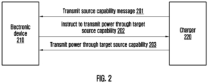
- FIG. 2 is a diagram illustrating an operation of an electronic device and a charger, according to various embodiments.
- an electronic device 210 may communicate with a charger 220 according to a USB type-C standard.
- the charger 220 may communicate with the electronic device 210 through VBUS pin(s) and CC pin(s).
- the charger 220 may be connected to a USB type-C cable bundle.
- a type-C cable bundle may include VBUS pin(s) and CC pin(s) and other pins (not shown), like SBU1, SBU2, or GND.
- the charger 220 may transmit a source capability message to the electronic device 210 after the communication between the electronic device 210 and the charger 220 is established.
- the charger 220 may transmit a source capability message as defined by a USB PD 2.0 standard through CC pin(s).
- the electronic device 210 may receive the source capability message from the charger 220.
- the source capability message may include at least one source capability indicating information on the voltage and current of power that may be transmitted by the charger 220 to the electronic device 210.
- a source capability may include one of or a combination of two or more of a power data object (PDO) or an augmented power data object (APDO).
- PDO is a source capability corresponding to a fixed voltage and may be, for example, a PDO corresponding to a voltage of 5 V and a current of 3 A, a PDO corresponding to a voltage of 9 V and a current of 2 A, or a PDO corresponding to a voltage of 12 V and a current of 1.5 A.
- the APDO may be a source capability that is programmable in a voltage range that is greater than or equal to a minimum voltage and less than or equal to a maximum voltage.
- the APDO may be a source capability corresponding to a voltage range between a minimum voltage and a maximum voltage and may be, for example, an APDO corresponding to a voltage range (e.g., a voltage range that is greater than or equal to 3 V and less than or equal to 5.9 V) having a minimum voltage of 3 V and a maximum voltage of 9 V and a current of 3 A.
- a source capability message may have to include an essential vSafe5V PDO (e.g., a PDO corresponding to 5 V).
- an essential vSafe5V PDO e.g., a PDO corresponding to 5 V.
- the electronic device 210 may determine that charging based on a source capability message is unavailable not including the PDO corresponding to 5 V.
- the electronic device 210 may instruct the charger 220 to transmit power through a target source capability.
- the instruction to transmit power through the target source capability may be transmitted through CC pin(s) of a USB type-C cable bundle.
- the electronic device 210 may select the target source capability among source capabilities included in the source capability message received from the charger 220. In addition, the electronic device 210 may exclude the received source capability message and may determine a predetermined source capability as the target source capability. The operation of electronic device 210, which determines the target source capability, is described below with reference to FIG. 3 .
- the charger 220 may transmit power to the electronic device 210 through the target source capability.
- the electronic device 210 may receive power through the target source capability from the charger 220.
- power may be transmitted from the charger 220 to the electronic device 210 via the VBUS pin(s) of a USB type-C cable.
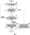
- FIG. 3 is a diagram illustrating an operation of an electronic device receiving power from a charger, according to various embodiments.
- a processor may receive a source capability message from the charger (e.g., the charger 220 of FIG. 2 ).
- the source capability message may include at least one source capability, and a source capability may indicate the performance information of voltage and current of power that may be transmitted by the charger to the electronic device.
- the processor may determine (or identify) whether charging is available based on the source capability message received from the charger.
- the processor may determine whether charging based on a source capability message is available, based at least on a voltage among received source capability messages.
- the processor may determine whether charging based on a source capability message is available, based on a USB PD standard. For example, if the source capability message received from the charger does not satisfy the USB PD standard, the processor may determine that charging is unavailable based on the source capability message. The operation of determining whether charging based on a source capability message is available, based on the USB PD standard, is described below with reference to FIGS. 4 and 5 .
- the processor may determine whether charging based on a source capability message is available, based on whether a logical error is in a source capability included in the source capability message. For example, if a minimum voltage of an APDO included in a source capability message is less than a maximum voltage, the processor may determine that charging is unavailable based on the source capability message.
- the operation of determining whether charging based on a source capability message is available, based on whether a logical error is in a source capability is described below with reference to FIG. 6 .
- the processor may determine whether charging based on a source capability message is available, based on a voltage related to the electronic device.
- the voltage related to the electronic device may include one of or a combination of one or more of a maximum voltage of power that is receivable by the electronic device or a minimum voltage required for the charging of the electronic device. For example, if a source capability message does not include a source capability of a voltage greater than or equal to the minimum voltage required for the charging of the electronic device, the processor may determine that charging is unavailable based on the source capability message. If a source capability message does not include a source capability of a voltage less than or equal to the maximum voltage that is receivable by the electronic device, the processor may determine that charging is unavailable based on the source capability message.
- the operation of determining whether charging based on a source capability message is available, based on the maximum voltage of power that is receivable by the electronic device or the minimum voltage required for the charging of the electronic device is described below with reference to FIGS. 7 to 9 .
- the processor may determine whether charging based on a source capability message is available, based on one of or a combination of two or more of the voltage (e.g., the maximum voltage of power that is receivable by the electronic device or the minimum voltage required for the charging of the electronic device) related to the electronic device, whether the source capability message satisfies the USB PD standard, or whether a logical error is in a source capability included in the source capability message.
- the voltage e.g., the maximum voltage of power that is receivable by the electronic device or the minimum voltage required for the charging of the electronic device
- the processor may determine whether charging is available based sequentially on whether a logical error is in a source capability included in the source capability message, the voltage related to the electronic device, and whether the source capability message satisfies the USB PD standard.
- the processor may determine whether charging based on a source capability message is available, based on whether the source capability message satisfies the USB PD standard. Then, if the processor does not determine that charging based on a source capability message is unavailable, based on whether the source capability message satisfies the USB PD standard, the processor may determine whether charging based on a source capability message is available, based on whether a logical error is in a source capability included in the source capability message.
- the processor may determine whether charging based on a source capability message is available, based on the voltage related to the electronic device.
- the processor may determine whether charging is available based on one of the voltage related to the electronic device or whether a source capability message satisfies the USB PD standard together with whether a logical error is in a source capability included in the source capability message.
- the processor may determine whether charging based on a source capability message is available, based on whether a logical error is in a source capability included in the source capability message. Then, if the processor does not determine that charging is unavailable based on whether a logical error is in a source capability included in the source capability message, the processor may determine whether charging based on a source capability message is available, based on the voltage related to the electronic device. Alternatively, if the processor does not determine that charging is unavailable based on whether a logical error is in a source capability included in the source capability message, the processor may determine whether charging based on a source capability message is available, based on the USB PD standard.
- the processor may determine whether to request a source capability message again from the charger. For example, based on the number of determining that charging based on a source capability message is unavailable, the processor may determine whether to instruct the charger to retransmit a source capability message. If the number of determining that charging is unavailable based on the source capability message received from the charger is greater than or equal to a threshold number, the processor may omit the instructing of the charger to retransmit a source capability message. If the number of determining that charging is unavailable based on the source capability message received from the charger is less than the threshold number, the processor may instruct the charger to retransmit a source capability message.
- the processor in response to charging being unavailable based on the received source capability message, may instruct the charger to retransmit a source capability message. If the number of determining that charging is unavailable based on the source capability message from the charger is greater than or equal to a threshold number, the processor may omit the instructing to retransmit a source capability message.
- the processor may instruct the charger to retransmit the source capability message.
- the charger may retransmit the source capability message to the electronic device.
- the processor may resume communication with the charger after blocking the communication with the charger and may instruct the charger to retransmit a source capability message. For example, the processor may resume communication with the charger after blocking the communication with the charger by initializing CC pin(s). If communication with the electronic device is resumed, the charger may retransmit the source capability message to the electronic device.
- the processor may repeat the operations of receiving the source capability message and determining whether charging is available for the retransmitted source capability message. Specifically, the processor may receive the source capability message retransmitted from the charger. The processor may determine whether charging is available based on the retransmitted source capability message.
- the processor may instruct the charger to exclude the source capability message received from the charger and transmit power to a predetermined source capability. For example, in response to the number of determining that charging is unavailable based on the source capability message being greater than or equal to the threshold number, the processor may instruct the charger to transmit power through a target source capability independent of a plurality of source capability messages received from the charger.
- the target source capability may be predetermined independently of the source capability messages.
- the target source capability may not be related to the source capability message received from the charger.
- the target source capability may be predetermined based on the USB PD standard.
- the processor may determine the target source capability to have a voltage of 5 V and a current of 3 A, based on a PDO (e.g., a vSafe5V PDO) corresponding to 5 V, which should be included in a source capability message of the charger that complies the USB PD standard.
- a PDO e.g., a vSafe5V PDO
- the electronic device may perform charging with a predetermined source capability instead of performing charging based on the source capability message. For example, if charging is performed based on a bad source capability message, the electronic device may receive a bad source capability message such that the electronic device may be at least substantially uncharged, slowly charged, or inefficiently charged. If receiving a bad source capability message, the electronic device may determine charging is unavailable based on the bad source capability message, may exclude the bad source capability message, and may instruct the charger to transmit power through a predetermined source capability independently. As a result, even if receiving a bad source capability message, the electronic device may receive power from the charger through the predetermined source capability.
- the processor may instruct the charger to transmit power through a source capability determined based on the source capability message.
- the processor may select a candidate source capability among source capabilities included in the source capability message received from the charger.
- the processor may select a candidate source capability based on a maximum voltage of receivable power of the electronic device.
- a PDO corresponding to a fixed voltage the processor may select a PDO, in which a voltage corresponding to the PDO is less than or equal to the maximum voltage of the receivable power of the electronic device, as a candidate source capability.
- the processor may select an APDO, in which a voltage range corresponding to the APDO includes a voltage value that is less than the maximum voltage of the receivable power of the electronic device, as a candidate source capability.
- the processor may select a candidate source capability based on the minimum voltage required for the charging of the electronic device.
- the processor may select a PDO, in which a voltage corresponding to the PDO is greater than or equal to the minimum voltage required for the charging of the electronic device, as a candidate source capability.
- the processor may select an APDO, in which a voltage range corresponding to the APDO includes a voltage value that is greater than or equal to the minimum voltage required for the charging of the electronic device, as a candidate source capability.
- the processor may determine the target source capability among candidate source capabilities, based on the size of power of the candidate source capabilities.
- the processor may instruct the charger to transmit power through the determined target source capability.
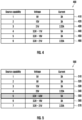
- FIGS. 4 and 5 are diagrams each illustrating an operation of an electronic device determining whether charging based on a source capability message is available, based on a USB PD standard, according to various embodiments.
- the electronic device may communicate with a charger according to the USB PD standard.
- the charger may transmit a source capability message that satisfies the USB PD standard to the electronic device.
- the source capability message transmitted from the charger to the electronic device may include a PDO corresponding to a predetermined voltage. For example, if satisfying the USB PD standard, the source capability message may include a PDO corresponding to 5 V If satisfying the USB PD standard and including an APDO, the source capability message may have a maximum voltage of a voltage range corresponding to the APDO is greater than or equal to a threshold voltage. For example, if satisfying the USB PD standard, the source capability message may have the maximum voltage of the voltage range corresponding to the APDO being greater than or equal to 5.9 V
- a processor of the electronic device may determine that charging is unavailable based on the source capability message.
- the electronic device in response to the source capability message not satisfying the USB PD standard, by determining that charging based on a source capability message is unavailable, the electronic device may instruct the charger to retransmit a source capability message or may exclude the received source capability message and instruct the charger to transmit power to a predetermined source capability.
- the charger may transmit a source capability message that does not satisfy the USB PD standard to the electronic device.
- the electronic device may receive a source capability message that does not satisfy the USB PD standard.
- communication between the charger and the electronic device may be performed abnormally without following the USB PD standard, for example, due to a problem of a cable for connecting the charger to the electronic device and/or a problem of the charger or the electronic device.
- the source capability message may be corrupted, and the electronic device may receive the source capability message that does not satisfy the USB PD standard.
- the source capability message that does not satisfy the USB PD standard may indicate one of or a combination of two or more of the problem of the electronic device, the problem of the charger, or the problem of communication between the electronic device and the charger. Thus, the reliability of the received source capability message may be low.
- the processor may determine whether the source capability message satisfies the USB PD standard, based at least on a voltage of the source capability message. The processor may determine that charging is available based on the source capability message when the source capability message satisfies the USB PD standard. The processor may determine that charging is unavailable based on the source capability message when the source capability message does not satisfy the USB PD standard.
- the processor may determine that charging is unavailable based on the source capability message.
- the processor may receive a source capability message 400 from the charger.
- the source capability message 400 may include a first source capability 410, a second source capability 420, a third source capability 430, a fourth source capability 440, a fifth source capability 450, and a sixth source capability 460.
- the first source capability 410, the second source capability 420, and the third source capability 430 may be PDOs corresponding to a fixed voltage and may respectively correspond to 9 V, 15 V, and 20 V.
- the fourth source capability 440, the fifth source capability 450, and the sixth source capability 460 may be APDOs corresponding to a voltage range and may respectively correspond to a voltage range having a minimum voltage of 3.3 V and a maximum voltage of 11 V, a voltage range having a minimum voltage of 3.3 V and a maximum voltage of 16 V, and a voltage range having a minimum voltage of 3.3 V and a maximum voltage of 21 V.
- the processor may determine that charging is unavailable based on the source capability message 400.
- a source capability message includes an APDO
- the processor may determine that charging based on a source capability message is available, based on a maximum voltage of a voltage range corresponding to the APDO.
- the processor may determine charging is unavailable based on the source capability message. If the source capability message includes a plurality of APDOs, in response to a maximum voltage of a voltage range corresponding to at least one APDO being less than the predetermined threshold voltage, the processor may determine charging is unavailable based on the source capability message.
- the processor may receive a source capability message 500 from the charger.
- the source capability message 500 may include a first source capability 510, a second source capability 520, a third source capability 530, a fourth source capability 540, a fifth source capability 550, a sixth source capability 560, and a seventh source capability 570.
- the first source capability 510, the second source capability 520, the third source capability 530, and the fourth source capability 540 may be PDOs corresponding to a fixed voltage and may respectively correspond to 5 V, 9 V, 15 V, and 20 V.
- the fifth source capability 550, the sixth source capability 560, and the seventh source capability 570 may be APDOs corresponding to a voltage range and may respectively correspond to a voltage range having a minimum voltage of 3.3 V and a maximum voltage of 4.8 V, a voltage range having a minimum voltage of 3.3 V and a maximum voltage of 16 V, and a voltage range having a minimum voltage of 3.3 V and a maximum voltage of 21 V.
- the processor may determine that charging is unavailable based on the source capability message 500.
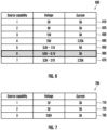
- FIG. 6 is a diagram illustrating an operation of an electronic device determining whether charging based on a source capability message is available, based on whether a logical error is in a source capability, according to various embodiments.
- the processor may determine whether charging based on a source capability message is available, based on whether a logical error is in at least one source capability included in the source capability message.
- the processor may determine charging is unavailable based on the source capability message in response to a logical error being in at least one source capability included in the source capability message.
- the processor may determine whether a logical error is in at least one source capability, based at least on a voltage of the source capability message.
- the source capability message may include an APDO corresponding to a voltage range.
- the voltage range corresponding to the APDO is expressed by a voltage that is greater than or equal to a minimum voltage and less than or equal to a maximum voltage by using the minimum voltage and the maximum voltage. If the minimum voltage of the voltage range corresponding to the APDO included in the source capability message is greater than the maximum voltage, the processor may determine that the APDO has a logical error.
- the processor may receive a source capability message 600 from the charger.
- the source capability message 600 may include a first source capability 610, a second source capability 620, a third source capability 630, a fourth source capability 640, a fifth source capability 650, a sixth source capability 660, and a seventh source capability 670.
- the first source capability 610, the second source capability 620, the third source capability 630, and the fourth source capability 640 may be PDOs corresponding to a fixed voltage and may respectively correspond to 5 V, 9 V, 16 V, and 20 V.
- the fifth source capability 650, the sixth source capability 660, and the seventh source capability 670 may be APDOs corresponding to a voltage range and may respectively correspond to a voltage range having a minimum voltage of 3.3 V and a maximum voltage of 11 V, a voltage range having a minimum voltage of 5.8 V and a maximum voltage of 4.1 V, and a voltage range having a minimum voltage of 3.3 V and a maximum voltage of 21 V.
- the processor may determine charging is unavailable based on the source capability message 600, based on the minimum voltage of 5.8 V of the voltage range exceeding the maximum voltage of 4.1 V of the voltage range corresponding to the sixth source capability 660 among the source capabilities included in the source capability message 600.
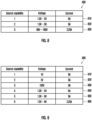
- FIGS. 7 to 9 are diagrams each illustrating an operation of determining whether charging based on a source capability message is available, based on a voltage related to an electronic device, according to various embodiments.
- a processor may determine whether charging based on a source capability message is available, based on one of or a combination of two or more of a minimum voltage required for the charging of the electronic device or a maximum voltage of power receivable by the electronic device.
- the processor may determine whether each source capability included in a source capability message is usable for the charging of the electronic device.
- the processor may determine whether a source capability is usable for the charging of the electronic device based on one of or a combination of two or more of the minimum voltage required for the charging of the electronic device or the maximum voltage of power receivable by the electronic device.
- the source capability may be a PDO corresponding to a fixed voltage. If a voltage corresponding to a PDO exceeds the maximum voltage of power receivable by the electronic device, the processor may determine that the PDO is not usable for the charging of the electronic device. If a voltage corresponding to a PDO is less than the minimum voltage required for the charging of the electronic device, the processor may determine the PDO is not usable for the charging of the electronic device. If a voltage corresponding to a PDO is greater than or equal to the minimum voltage required for the charging of the electronic device and less than or equal to the maximum voltage of power receivable by the electronic device, the processor may determine that the PDO is usable for the charging of the electronic device.
- the source capability may be an APDO corresponding to a voltage range. If a minimum voltage of a voltage range corresponding to an APDO exceeds the maximum voltage of power receivable by the electronic device, the processor may determine that the APDO is not usable for the charging of the electronic device. If a maximum voltage of a voltage range corresponding to an APDO is less than the minimum voltage required for the charging of the electronic device, the processor may determine the APDO is not usable for the charging of the electronic device.
- a voltage range corresponding to an APDO includes a voltage value that is greater than or equal to the minimum voltage required for the charging of the electronic device and less than or equal to the maximum voltage of power receivable by the electronic device
- the processor may determine that the APDO is usable for the charging of the electronic device. For example, if a minimum voltage of a voltage range corresponding to an APDO is less than or equal to the maximum voltage of power receivable by the electronic device and a maximum voltage of the voltage range corresponding to the APDO is greater than or equal to the minimum voltage required for the charging of the electronic device, the processor may determine that the APDO is usable for the charging of the electronic device.
- the processor may determine whether charging based on a source capability message is available, based on whether a source capability included in the source capability message is usable for the charging of the electronic device. For example, if the source capability included in the source capability message is usable for the charging of the electronic device, the processor may determine that charging is available based on the source capability message. If the source capability included in the source capability message is not usable for the charging of the electronic device, the processor may determine that charging is unavailable based on the source capability message.
- the processor may receive a source capability message including a plurality of source capabilities from a charger. If at least one source capability among the plurality of source capabilities included in the source capability message is usable for the charging of the electronic device, the processor may determine that charging is available based on the source capability message. If all the plurality of source capabilities included in the source capability message is not usable for the charging of the electronic device, the processor may determine that charging is unavailable based on the source capability message.
- the processor may receive a source capability message 700 from the charger.
- the source capability message 700 may include a first source capability 710, a second source capability 720, and a third source capability 730.
- the first source capability 710, the second source capability 720, and the third source capability 730 may be PDOs corresponding to a fixed voltage and may respectively correspond to 2 V, 3 V, and 100 V.
- the processor may determine that the first source capability 710 is not usable for the charging of the electronic device. Based on the voltage of 3 V corresponding to the second source capability 720 being less than the minimum voltage (e.g., 5 V) required for the charging of the electronic device, the processor may determine that the second source capability 720 is not usable for the charging of the electronic device. Based on the voltage of 100 V corresponding to the third source capability 730 exceeding a maximum voltage (e.g., 50 V) of power receivable by the electronic device, the processor may determine that the third source capability 730 is not usable for the charging of the electronic device.
- a minimum voltage e.g., 5 V
- the processor may determine that charging is unavailable based on the source capability message 700.
- the processor may receive a source capability message 800 from the charger.
- the source capability message 800 may include a first source capability 810, a second source capability 820, and a third source capability 830.
- the first source capability 810, the second source capability 820, and the third source capability 830 may be APDOs corresponding to a voltage range and may respectively correspond to a voltage range having a minimum voltage of 1.3 V and a maximum voltage of 2 V, a voltage range having a minimum voltage of 1.3 V and a maximum voltage of 3 V, and a voltage range having a minimum voltage of 99 V and a maximum voltage of 100 V
- the processor may determine that the first source capability 810 is not usable for the charging of the electronic device. Based on the maximum voltage of 3 V of the voltage range corresponding to the second source capability 820 being less than the minimum voltage (e.g., 5 V) required for the charging of the electronic device, the processor may determine that the second source capability 820 is not usable for the charging of the electronic device.
- the processor may determine that the third source capability 830 is not usable for the charging of the electronic device.
- the processor may determine that charging is unavailable based on the source capability message 800.
- the processor may receive a source capability message 900 from the charger.
- the source capability message 900 may include a first source capability 910, a second source capability 920, a third source capability 930, a fourth source capability 940, a fifth source capability 950, and a sixth source capability 960.
- the first source capability 910, the second source capability 920, and the third source capability 930 may be PDOs corresponding to a fixed voltage and may respectively correspond to 1 V, 2 V, and 100 V.
- the fourth source capability 940, the fifth source capability 950, and the sixth source capability 960 may be APDOs corresponding to a voltage range and may respectively correspond to a voltage range having a minimum voltage of 1.3 V and a maximum voltage of 2 V, a voltage range having a minimum voltage of 1.3 V and a maximum voltage of 3 V, and a voltage range having a minimum voltage of 1.5 V and a maximum voltage of 4 V.
- the processor may determine that the first source capability 910 is not usable for the charging of the electronic device. Based on the voltage of 2 V corresponding to the second source capability 920 being less than the minimum voltage (e.g., 5 V) required for the charging of the electronic device, the processor may determine that the second source capability 920 is not usable for the charging of the electronic device. Based on the voltage of 100 V corresponding to the third source capability 930 exceeding the maximum voltage (e.g., 50 V) of power receivable by the electronic device, the processor may determine that the third source capability 930 is not usable for the charging of the electronic device.
- the processor may determine that the third source capability 930 is not usable for the charging of the electronic device.
- the processor may determine that the fourth source capability 940 is not usable for the charging of the electronic device. Based on the maximum voltage of 3 V of the voltage range corresponding to the fifth source capability 950 being less than the minimum voltage (e.g., 5 V) required for the charging of the electronic device, the processor may determine that the fifth source capability 950 is not usable for the charging of the electronic device.
- the processor may determine that the sixth source capability 960 is not usable for the charging of the electronic device.
- the processor may determine that charging is unavailable based on the source capability message 900.
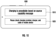
- FIG. 10 is a diagram illustrating an operation of an electronic device displaying whether charging is available through a display module, according to various embodiments.
- an electronic device 1000 may display a guidance message through the display module (e.g., the display module 160 of FIG. 1 ) when charging based on a source capability message is unavailable received from a charger (e.g., the charger 220 of FIG. 2 ).
- the guidance message may include a message explaining that charging is unavailable based on the source capability message to a user.
- the guidance message may include a message suggesting recommended actions to the user in addition to information that charging is unavailable based on the source capability message.
- a processor of the electronic device 1000 may display a guidance message including a message 1010 explaining that charging is unavailable based on the source capability message to the user and a message 1020 suggesting recommended actions to the user through a display.
- the electronic device may display a user-friendly display by displaying the message explaining that charging is unavailable based on the source capability message to the user.
- the electronic device may suggest required actions to the user such that charging may be available based on the source capability message by displaying the message suggesting recommended actions to the user.
- the electronic device 101; 210 may include the memory 130 storing computer-executable instructions and the processor 120 for executing the instructions by accessing the memory 130.
- the instructions when executed by the processor, may cause the electronic device to receive a source capability message of the charger 220 from the charger 220.
- the instructions when executed by the processor, may cause the electronic device to determine whether charging is available based on the received source capability message.
- the instructions when executed by the processor, may cause the electronic device to, in response to charging being unavailable based on the received source capability message, instruct the charger 220 to retransmit a source capability message.
- the instructions when executed by the processor, may cause the electronic device to, based on the number of determining that charging is unavailable based on the source capability message received from the charger 220, exclude the source capability message and instruct the charger 220 to transmit power to a predetermined source capability.
- the instructions when executed by the processor, may cause the electronic device to determine whether charging based on a source capability message is available, based at least on a voltage among the received source capability messages.
- the instructions when executed by the processor, may cause the electronic device to, in response to a PDO corresponding to a predetermined voltage being not included in the received source capability message of the charger 220, determine charging is unavailable based on the received source capability message of the charger 220.
- the instructions when executed by the processor, may cause the electronic device to, in response to a maximum voltage of a voltage range corresponding to an APDO included in the received source capability message of the charger 220 being less than a predetermined threshold voltage, determine charging is unavailable based on the received source capability message of the charger 220.
- the instructions when executed by the processor, may cause the electronic device to, in response to a minimum voltage of a voltage range corresponding to an APDO included in the received source capability message of the charger 220 being greater than the maximum voltage of the voltage range, determine charging is unavailable based on the received source capability message of the charger 220.
- the instructions when executed by the processor, may cause the electronic device to, based on one of or a combination of two or more of a minimum voltage required for the charging of the electronic device 101; 210 or a maximum voltage of power receivable by the electronic device 101; 210, determine whether a source capability comprised in the received source capability message of the charger 220 is usable for the charging of the electronic device 101; 210.
- the instructions when executed by the processor, may cause the electronic device to, in response to at least one of source capabilities comprised in the received source capability message of the charger 220 being usable for the charging of the electronic device 101; 210, determine charging is available based on the received source capability message of the charger 220.
- the instructions when executed by the processor, may cause the electronic device to, in response to a voltage corresponding to a PDO included in the received source capability message of the charger 220 being less than the minimum voltage required for the charging of the electronic device 101; 210, determine that the source capability is not usable for the charging of the electronic device 101; 201.
- the instructions when executed by the processor, may cause the electronic device to, in response to a maximum voltage of a voltage range corresponding to an APDO included in the received source capability message of the charger 220 being less than the minimum voltage required for the charging of the electronic device 101; 210, determine that the source capability is not usable for the charging of the electronic device 101; 201.
- the instructions when executed by the processor, may cause the electronic device to receive a source capability message including a PDO and an APDO from the charger 220.
- the instructions when executed by the processor, may cause the electronic device to, in response to a voltage corresponding to the PDO and a maximum voltage of a voltage range corresponding to the APDO being less than the minimum voltage required for the charging of the electronic device 101; 210, determine that the source capability is not usable for the charging of the electronic device 101; 201.
- the instructions when executed by the processor, may cause the electronic device to, in response to a voltage corresponding to a PDO included in the received source capability message of the charger 220 exceeding the maximum voltage of the power receivable by the electronic device 101; 210, determine that the source capability is not usable for the charging of the electronic device 101; 201.
- the instructions when executed by the processor, may cause the electronic device to, in response to a minimum voltage of a PDO included in the received source capability message of the charger 220 exceeding the maximum voltage of the power receivable by the electronic device 101; 210, determine that the source capability is not usable for the charging of the electronic device 101; 201.
- the instructions when executed by the processor, may cause the electronic device to receive a source capability message including a PDO and an APDO from the charger 220.
- the instructions when executed by the processor, may cause the electronic device to, in response to a voltage corresponding to the PDO and a maximum voltage of a voltage range corresponding to the APDO being less than the minimum voltage required for the charging of the electronic device 101; 210, determine that the source capability is not usable for the charging of the electronic device 101; 201.
- the instructions when executed by the processor, may cause the electronic device to resume communication with the charger 220 after blocking the communication with the charger 220 and instruct the charger 220 to retransmit a source capability message.
- the instructions when executed by the processor, may cause the electronic device to receive the source capability message retransmitted from the charger 220.
- the instructions when executed by the processor, may cause the electronic device to determine whether charging is available based on the retransmitted source capability message.
- the instructions when executed by the processor, may cause the electronic device to, in response to the number of determining that charging is unavailable based on the source capability message being greater than or equal to a threshold number, instruct the charger 220 to transmit power to a source capability independent of a plurality of source capability messages received from the charger 220.
- an operating method, implemented by a processor, of the electronic device 101; 210 may include receiving a source capability message of the charger 220 from the charger 220.
- the operating method, implemented by a processor, of the electronic device 101; 210 may include determining whether charging is available based on the received source capability message.
- the operating method, implemented by a processor, of the electronic device 101; 210 may include, in response to charging being unavailable based on the received source capability message, instructing the charger 220 to retransmit a source capability message.
- the operating method, implemented by a processor, of the electronic device 101; 210 may include, based on the number of determining that charging is unavailable based on the source capability message received from the charger 220, excluding the source capability message and instructing the charger 220 to transmit power to a predetermined source capability.
- an operation of determining whether charging is available may include determining whether charging based on a source capability message is available, based at least on a voltage among the received source capability messages.
- the operation of determining whether charging is available may include, in response to a PDO corresponding to a predetermined voltage being not included in the received source capability message of the charger 220, determining charging is unavailable based on the received source capability message of the charger 220.
- the operation of determining whether charging is available may include, in response to a maximum voltage of a voltage range corresponding to an APDO included in the received source capability message of the charger 220 being less than a predetermined threshold voltage, determining charging is unavailable based on the received source capability message of the charger 220.
- the operation of determining whether charging is available may include, in response to a minimum voltage of a voltage range corresponding to an APDO included in the received source capability message of the charger 220 being greater than the maximum voltage of the voltage range, determining charging is unavailable based on the received source capability message of the charger 220.
- the operation of determining whether charging is available may include, based on one of or a combination of two or more of a maximum voltage of power, determining whether a source capability included in the received source capability message of the charger 220 is usable for the charging of the electronic device 101; 210.
- the operation of determining whether charging is available may include, in response to at least one of source capabilities comprised in the received source capability message of the charger 220 being usable for the charging of the electronic device 101; 210, determining charging is available based on the received source capability message of the charger 220.
- the above-described hardware devices may be configured to act as one or more software modules in order to perform the operations of the above-described examples, or vice versa.
- the electronic device may be one of various types of electronic devices.
- the electronic device may include, for example, a portable communication device (e.g., a smartphone), a computer device, a portable multimedia device, a portable medical device, a camera, a wearable device, or a home appliance device. According to an embodiment, the electronic device is not limited to those described above.
- a or B at least one of A and B, “at least one of A or B”, “A, B or C”, “at least one of A, B and C", and “A, B, or C,” each of which may include any one of the items listed together in the corresponding one of the phrases, or all possible combinations thereof.
- Terms such as “first”, “second”, or “first” or “second” may simply be used to distinguish the component from other components in question and may refer to components in other aspects (e.g., importance or order) is not limited.
- a component e.g., a first component
- operatively or “communicatively”, as “coupled with”, “coupled to”, “connected with”, or “connected to” another component
- the component may be coupled with the other component directly (e.g., by wire), wirelessly, or via a third component.
- module may include a unit implemented in hardware, software, or firmware, and may interchangeably be used with other terms, for example, “logic,” “logic block,” “part,” or “circuitry”.
- a module may be a single integral component, or a minimum unit or part thereof, adapted to perform one or more functions.
- the module may be implemented in a form of an ASIC.
- Various embodiments as set forth herein may be implemented as software (e.g., the program 140) including one or more instructions that are stored in a storage medium (e.g., the internal memory 136 or the external memory 138) that is readable by a machine (e.g., the electronic device 101).
- a processor e.g., the processor 120
- the one or more instructions may include code generated by a compiler or code executable by an interpreter.
- the machine-readable storage medium may be provided in the form of a non-transitory storage medium.
- non-transitory simply means that the storage medium is a tangible device, and does not include a signal (e.g., an electromagnetic wave), but this term does not differentiate between where data is semi-permanently stored in the storage medium and where the data is temporarily stored in the storage medium.
- a signal e.g., an electromagnetic wave
- a method may be included and provided in a computer program product.
- the computer program product may be traded as a product between a seller and a buyer.
- the computer program product may be distributed in the form of a machine-readable storage medium (e.g., a compact disc read-only memory (CD-ROM)), or be distributed (e.g., downloaded or uploaded) online via an application store (e.g., PlayStoreTM), or between two user devices (e.g., smartphones) directly. If distributed online, at least part of the computer program product may be temporarily generated or at least temporarily stored in the machine-readable storage medium, such as memory of the manufacturer's server, a server of the application store, or a relay server.
- each component e.g., a module or a program of the above-described components may include a single entity or multiple entities, and some of the multiple entities may be separately disposed in different components.
- one or more of the above-described components may be omitted, or one or more other components may be added.
- a plurality of components e.g., modules or programs
- the integrated component may still perform one or more functions of each of the components in the same or similar manner as they are performed by a corresponding one among the components before the integration.
- operations performed by the module, the program, or another component may be carried out sequentially, in parallel, repeatedly, or heuristically, or one or more of the operations may be executed in a different order or omitted, or one or more other operations may be added.
Landscapes
- Engineering & Computer Science (AREA)
- Theoretical Computer Science (AREA)
- Power Engineering (AREA)
- Physics & Mathematics (AREA)
- General Engineering & Computer Science (AREA)
- General Physics & Mathematics (AREA)
- Human Computer Interaction (AREA)
- Telephone Function (AREA)
- Charge And Discharge Circuits For Batteries Or The Like (AREA)
Applications Claiming Priority (2)
| Application Number | Priority Date | Filing Date | Title |
|---|---|---|---|
| KR1020220097532A KR20240019623A (ko) | 2022-08-04 | 2022-08-04 | 전자 장치의 충전을 위한 소스 캐퍼빌리티를 결정하기 위한 장치 및 방법 |
| PCT/KR2023/009952 WO2024029774A1 (ko) | 2022-08-04 | 2023-07-12 | 전자 장치의 충전을 위한 소스 캐퍼빌리티를 결정하기 위한 장치 및 방법 |
Publications (2)
| Publication Number | Publication Date |
|---|---|
| EP4498564A1 true EP4498564A1 (de) | 2025-01-29 |
| EP4498564A4 EP4498564A4 (de) | 2025-07-16 |
Family
ID=89849209
Family Applications (1)
| Application Number | Title | Priority Date | Filing Date |
|---|---|---|---|
| EP23850281.9A Pending EP4498564A4 (de) | 2022-08-04 | 2023-07-12 | Vorrichtung und verfahren zur bestimmung der quellenkapazität zum laden einer elektronischen vorrichtung |
Country Status (4)
| Country | Link |
|---|---|
| US (1) | US20250158421A1 (de) |
| EP (1) | EP4498564A4 (de) |
| KR (1) | KR20240019623A (de) |
| WO (1) | WO2024029774A1 (de) |
Family Cites Families (9)
| Publication number | Priority date | Publication date | Assignee | Title |
|---|---|---|---|---|
| JP4479768B2 (ja) * | 2007-09-10 | 2010-06-09 | トヨタ自動車株式会社 | 自動車および自動車の充電方法 |
| KR20110022515A (ko) * | 2009-08-27 | 2011-03-07 | 한국전자통신연구원 | 차량의 충전 제어 방법 및 이를 위한 충전 제어 장치 |
| KR101214448B1 (ko) * | 2012-03-13 | 2012-12-21 | 한국전기연구원 | 충전기 간 통신 네트워크를 포함하여 구성되는 충전 설비와 그 충전 제어 방법 |
| KR102215085B1 (ko) * | 2013-12-23 | 2021-02-15 | 삼성전자주식회사 | 충전 기기 및 그 동작 방법 |
| KR101664557B1 (ko) * | 2014-09-16 | 2016-10-13 | 현대자동차주식회사 | 충전 차량, 충전 차량의 제어기 동작 방법 및 충전 시스템의 동작 방법 |
| US10050457B2 (en) * | 2015-08-07 | 2018-08-14 | Paypal, Inc. | Smart charging of user devices |
| WO2020132891A1 (zh) * | 2018-12-25 | 2020-07-02 | 华为技术有限公司 | 可选配终端充电的方法、图形用户界面及电子设备 |
| KR102782434B1 (ko) * | 2019-03-26 | 2025-03-18 | 삼성전자 주식회사 | 무선 전력 수신 장치 및 그 제어 방법 |
| EP4187750A4 (de) * | 2020-10-23 | 2024-03-06 | Samsung Electronics Co., Ltd. | Schnellladeverfahren und elektronische vorrichtung |
-
2022
- 2022-08-04 KR KR1020220097532A patent/KR20240019623A/ko active Pending
-
2023
- 2023-07-12 WO PCT/KR2023/009952 patent/WO2024029774A1/ko not_active Ceased
- 2023-07-12 EP EP23850281.9A patent/EP4498564A4/de active Pending
-
2024
- 2024-12-31 US US19/007,125 patent/US20250158421A1/en active Pending
Also Published As
| Publication number | Publication date |
|---|---|
| KR20240019623A (ko) | 2024-02-14 |
| US20250158421A1 (en) | 2025-05-15 |
| WO2024029774A1 (ko) | 2024-02-08 |
| EP4498564A4 (de) | 2025-07-16 |
Similar Documents
| Publication | Publication Date | Title |
|---|---|---|
| US20230259188A1 (en) | Electronic device comprising connector | |
| KR102822199B1 (ko) | 전자 장치 및 전자 장치에서 무선 충전 가이드 제공 방법 | |
| US20250096583A1 (en) | Electronic device and battery control method | |
| US20230300911A1 (en) | Wireless charging method and electronic device supporting same | |
| US20230402853A1 (en) | Electronic device for supporting fast battery charging | |
| US11973356B2 (en) | Method and electronic device for providing fast charging | |
| EP4395273B1 (de) | Elektronische vorrichtung zur bereitstellung einer rcs-funktion und betriebsverfahren dafür | |
| KR102944914B1 (ko) | 고속 충전 방법 및 전자 장치 | |
| US20230420960A1 (en) | Electronic device including battery pack, and operation method of electronic device | |
| US12308690B2 (en) | Electronic device and control method therefor | |
| US12315963B2 (en) | Electronic device and method of protecting battery in the electronic device | |
| EP4498564A1 (de) | Vorrichtung und verfahren zur bestimmung der quellenkapazität zum laden einer elektronischen vorrichtung | |
| US12294235B2 (en) | Electronic device for charging battery based on voltage of interface and method for controlling same | |
| EP4199535A1 (de) | Verfahren zum auffinden einer audioausgabevorrichtung unter verwendung einer stromversorgungsvorrichtung und stromversorgungsvorrichtung dafür | |
| US12050498B2 (en) | Electronic device and method of controlling discharge of external electronic device using the same | |
| US12608063B2 (en) | Power supply circuit and electronic device comprising same | |
| US20240022120A1 (en) | Method of providing wireless charging guide and electronic device performing same | |
| EP4373206A1 (de) | Verfahren zur durchführung von drahtloser kommunikation und elektronische vorrichtung zur unterstützung davon | |
| EP4583357A1 (de) | Verfahren und elektronische vorrichtung zum laden einer batterie | |
| EP4604628A1 (de) | Elektronische vorrichtung zur steuerung der übertragungsleistung und betriebsverfahren für elektronische vorrichtung | |
| EP4518169A1 (de) | Elektronische vorrichtung mit antenne | |
| US20250392145A1 (en) | Electronic device including charging cradle and method of operating same | |
| EP4258114A1 (de) | Dienstbetriebsverfahren und elektronische vorrichtung zur unterstützung davon | |
| US20250274857A1 (en) | Electronic device and method for identifying priority of connection, and non-transitory computer-readable storage medium | |
| KR20230171835A (ko) | 배터리 고속 충전을 지원하는 전자 장치 |
Legal Events
| Date | Code | Title | Description |
|---|---|---|---|
| STAA | Information on the status of an ep patent application or granted ep patent |
Free format text: STATUS: THE INTERNATIONAL PUBLICATION HAS BEEN MADE |
|
| PUAI | Public reference made under article 153(3) epc to a published international application that has entered the european phase |
Free format text: ORIGINAL CODE: 0009012 |
|
| STAA | Information on the status of an ep patent application or granted ep patent |
Free format text: STATUS: REQUEST FOR EXAMINATION WAS MADE |
|
| 17P | Request for examination filed |
Effective date: 20241023 |
|
| AK | Designated contracting states |
Kind code of ref document: A1 Designated state(s): AL AT BE BG CH CY CZ DE DK EE ES FI FR GB GR HR HU IE IS IT LI LT LU LV MC ME MK MT NL NO PL PT RO RS SE SI SK SM TR |
|
| A4 | Supplementary search report drawn up and despatched |
Effective date: 20250613 |
|
| RIC1 | Information provided on ipc code assigned before grant |
Ipc: H02J 7/00 20060101AFI20250606BHEP Ipc: G06F 1/26 20060101ALI20250606BHEP Ipc: G06F 3/06 20060101ALI20250606BHEP |
|
| DAV | Request for validation of the european patent (deleted) | ||
| DAX | Request for extension of the european patent (deleted) |