EP4498511A1 - Vier-vingt-dix-hybridkoppler - Google Patents
Vier-vingt-dix-hybridkoppler Download PDFInfo
- Publication number
- EP4498511A1 EP4498511A1 EP24190971.2A EP24190971A EP4498511A1 EP 4498511 A1 EP4498511 A1 EP 4498511A1 EP 24190971 A EP24190971 A EP 24190971A EP 4498511 A1 EP4498511 A1 EP 4498511A1
- Authority
- EP
- European Patent Office
- Prior art keywords
- input
- output
- assembly
- coupler
- unitary
- Prior art date
- Legal status (The legal status is an assumption and is not a legal conclusion. Google has not performed a legal analysis and makes no representation as to the accuracy of the status listed.)
- Pending
Links
Images



Classifications
-
- H—ELECTRICITY
- H01—ELECTRIC ELEMENTS
- H01P—WAVEGUIDES; RESONATORS, LINES, OR OTHER DEVICES OF THE WAVEGUIDE TYPE
- H01P5/00—Coupling devices of the waveguide type
- H01P5/12—Coupling devices having more than two ports
- H01P5/16—Conjugate devices, i.e. devices having at least one port decoupled from one other port
- H01P5/19—Conjugate devices, i.e. devices having at least one port decoupled from one other port of the junction type
- H01P5/22—Hybrid ring junctions
- H01P5/227—90° branch line couplers
-
- H—ELECTRICITY
- H01—ELECTRIC ELEMENTS
- H01P—WAVEGUIDES; RESONATORS, LINES, OR OTHER DEVICES OF THE WAVEGUIDE TYPE
- H01P5/00—Coupling devices of the waveguide type
- H01P5/12—Coupling devices having more than two ports
- H01P5/16—Conjugate devices, i.e. devices having at least one port decoupled from one other port
- H01P5/18—Conjugate devices, i.e. devices having at least one port decoupled from one other port consisting of two coupled guides, e.g. directional couplers
-
- H—ELECTRICITY
- H03—ELECTRONIC CIRCUITRY
- H03H—IMPEDANCE NETWORKS, e.g. RESONANT CIRCUITS; RESONATORS
- H03H7/00—Multiple-port networks comprising only passive electrical elements as network components
- H03H7/48—Networks for connecting several sources or loads, working on the same frequency or frequency band, to a common load or source
Definitions
- This description relates generally to electronic circuits and devices adapted to use signals, and in particular radio frequency signals.
- This description relates to a hybrid coupler, and more particularly to a ninety degree hybrid coupler.
- Couplers are electronic devices used to couple several electronic signals, and for example signals used in the radio frequency field, that is to say signals having frequencies between a few hertz and more than 300 kHz, for example between 3 kHz and 300 GHz.
- One embodiment overcomes all or part of the drawbacks of known couplers.
- One embodiment provides a coupler having a smaller footprint.
- One embodiment provides a coupler having less signal loss.
- the first input terminal of the unitary input element is a first input of said first assembly
- the second input terminal of the input unit element is a second input of said first assembly
- the first output terminal of the unitary output element is a first output of said first assembly
- the second output terminal of the unitary output element is a second output of said first assembly
- the first input of said assembly is configured to receive a first signal
- the second input of said assembly is configured to receive a second signal equal to the first phase-shifted signal
- the second signal is the first signal phase shifted by ninety degrees.
- the second signal is the first signal phase shifted by one hundred and eighty degrees.
- the coupler comprises at least one second assembly identical to the first assembly, in which the first output of said first assembly is connected to a first input of said second assembly, and the second output of said first assembly is connected to a second input of said second assembly.
- said unit elements all have the same dimensions.
- said unit elements have different dimensions.
- said unit elements are all placed in the same plane.
- said unit elements are all placed in different planes.
- said unit elements are placed in the form of a staircase.
- the first and second coils of said unit elements are windings of generally rectangular shape.
- the first and second coils of said unit elements are windings of general zig-zag shape.
- the coupler is a reversible coupler.
- the expressions “approximately”, “approximately”, “substantially”, and “of the order of” mean to within 10%, preferably to within 5%.
- FIG. 1 shows diagrams (A) and (B) of a coupler 100 according to one embodiment.
- Diagram (A) shows the electrical symbol of the coupler 100
- diagram (B) shows an equivalent electrical diagram of the coupler 100.
- the second signal is equal to the first signal phase shifted.
- the second signal is equal to the first signal phase shifted by ninety degrees.
- the second signal is equal to the first signal phase shifted by one hundred and eighty degrees.
- the third signal provided by the output OUT100, corresponds to the sum of the signals received at the input, and the fourth signal is a zero signal.
- the coupler 100 is reversible, and by inverting the inputs and outputs can be a signal separator circuit.
- Coupler 100 comprises two coils L101 and L102 and two capacitors C101 and C102.
- the input terminal of a coil is represented by a phase point, and the output terminal is left without a phase point. This means that the current through the coil flows from the input terminal to the output terminal.
- an input node of the coil L101 is connected, preferably connected, to the input IN100 of the coupler 100, and an output node of the coil L101 is connected, preferably connected, to the output OUT100 of the coupler 100.
- An input node of the coil L102 is connected, preferably connected, to the output ISO100 of the coupler 100, and an output node of the coil L102 is connected, preferably connected, to the output OUT100 of the coupler 100.
- a first node of the capacitor C101 is connected, preferably connected, to the input IN100 of the coupler 100, and a second node of the capacitor C101 is connected, preferably connected, to the output ISO100 of the coupler 100.
- a first node of the capacitor C102 is connected, preferably connected, to the input CPL100 of the coupler 100, and a second node of the capacitor C102 is connected, preferably connected, to the output OUT100 of the coupler 100.
- a physical implementation of the coupler 100 is described in connection with the figure 2 , and assemblies of these implementations forming a coupler are described in relation to the Figures 4 to 7 .
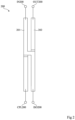
- FIG. 2 is a top view of a physical implementation of the coupler 100 described in connection with the figure 1 . More specifically, the figure 2 is a top view of a unit element 100 for forming the coupler 100.
- the unit element 100 comprises two coils 201 and 202 arranged in the form of a cross or "x". More particularly, the first coil 201 forms a first branch of the cross, or "x", and the second coil 202 forms a second branch of the cross, or "x".
- the two coils 201 are arranged in the form of a cross having a general "H" shape.
- all the branches of the cross formed by the coils 201 and 202 follow the same direction, and are thus parallel to each other.
- a cross having a general "H” shape is called the shape taken by the coils 201 and 202 shown in figure 2 .
- the capacitors of the coupler are in fact formed between the branches of the cross of the coils 201 and 202. More particularly, the capacitors represent the intrinsic capacities of the branches of the cross formed by the coils. According to a variant, capacitors can be added to the structure presented in figure 2 .
- first and second input terminals IN200 and CPL200 are both arranged on the same branch of the general "H” shape of the cross of the unit element 200.
- first and second output terminals OUT200 and ISO200 are both arranged on the same branch of the general "H” shape of the cross of the unit element 200. two on the other branch of the general "H” shape of the cross of the unit element 200.
- first and second input terminals IN200 and CPL200 are arranged on the same side (left side in figure 1 ) on a first large side of the unit element
- the first and second output terminals OUT200 and ISO200 are arranged on the same side (right side in figure 1 ) on the other large side of the unit element 200.
- first and second input terminals IN200 and CPL200 are not arranged on different branches of the general "H" shape of the cross of the unit element 200.
- first and second output terminals OUT200 and ISO200 are not arranged on different branches of the general "H” shape of the cross of the unit element 200.
- the dimensions of the unit element 200 make it possible to define the electrical characteristics of the coupler, such as the inductances of the coils 201 and 202 and the capacitances of the capacitors. It is therefore appropriate to adapt the dimensions of the unit element 200 to adjust the functionalities of the coupler that it forms.
- a unit element 200 makes it possible to implement a coupler of the type of the coupler 100, but it is also possible to assemble several unit elements 200 to obtain a coupler of the type of the coupler 100.
- An advantage of assembling several unit elements 200 to form is that this makes it possible to limit the size of a coupler 100 while making it possible to give it different shapes.
- a first example of an assembly of unit elements 200 is described in relation to the figure 3 , but this assembly has drawbacks. An embodiment of an assembly overcoming these drawbacks is described in relation to the figure 4 .
- figure 3 represents, very schematically, an example of an assembly 300 of unit elements of the type of the unit element 200 described in relation to the figure 2 .
- each unit element is represented very schematically by their general shape represented as a wire.
- the currents of the signals applied to the input terminals of the unit elements, and their directions, are represented by arrows.
- two "colors" of arrows are used to differentiate them.
- the assembly 300 forms a coupler of the type of the coupler 100 described in relation to the figure 1 , and therefore includes two inputs IN300 and CPL300, and two outputs OUT300 and ISO300.
- the unitary input element 301 is characterized in that its input terminals are connected to the inputs of the assembly. More particularly, a first input terminal of the element 301 is connected, preferably connected, to the input IN300 of the assembly, and a second input terminal of the element 301 is connected, preferably connected, to the input CPL300 of the assembly.
- the unitary output element 303 is characterized in that its output terminals are connected to the outputs of the assembly 300. More particularly, a first output terminal of the element 303 is connected, preferably connected, to the output OUT300 of the assembly 300, and a second terminal output of element 303 is connected, preferably connected, to the ISO300 output of the assembly 300.
- the intermediate unit element 302 is characterized in that it is positioned between the input 301 and output 303 unit elements. More particularly, a first input terminal of the element 302 is connected, preferably connected, to a first output terminal of the element 301, and a second input terminal of the element 302 is connected, preferably connected, to a second output terminal of the element 301. A first output terminal of the element 302 is connected, preferably connected, to a first input terminal of the element 303, and a second output terminal of the element 302 is connected, preferably connected, to a second input terminal of the element 303.
- a disadvantage of the assembly 300 is that the positioning of the unit elements presents constraints that can increase the area occupied by the assembly 300.
- parasitic coupling phenomena can appear at the connections between the unit elements.
- the unit elements are formed by coils, and, at the connections between the unit elements, two side-by-side coils are arranged in parallel and are crossed by the same current but in different directions, as shown in figure 3 .
- the unit elements must be spaced at a distance d300, which increases the bulk.
- FIG 4 represents, very schematically, an embodiment of an assembly 400 of unit elements of the type of the unit element 200 described in relation to the figure 2 .
- the assembly 400 forms a coupler of the type of the coupler 100 described in relation to the figure 1 , and therefore includes two inputs IN400 and CPL400, and two outputs OUT400 and ISO400.
- the unitary input element 401 is characterized in that its input terminals are connected to the inputs of the assembly. More particularly, a first input terminal of the element 401 is connected, preferably connected, to the input IN400 of the assembly 400, and a second input terminal of the element 401 is connected, preferably connected, to the input CPL400 of the assembly 400.
- the unitary output element 403 is characterized in that its output terminals are connected to the outputs of the assembly 400. More particularly, a first output terminal of the element 403 is connected, preferably connected, to the output OUT400 of the assembly 400, and a second output terminal of the element 403 is connected, preferably connected, to the output ISO400 of the assembly 400.
- the intermediate unit element 402 is characterized in that it is connected to the input unit elements 401 and output unit elements 403. More particularly, a first input terminal of the element 402 is connected, preferably connected, to a first output terminal of the element 401, and a second input terminal of the element 402 is connected, preferably connected, to a second output terminal of the element 401. A first output terminal of the element 402 is connected, preferably connected, to a first input terminal of the element 403, and a second output terminal of the element 403 is connected, preferably connected, to a second output terminal of the element 401. element 402 is connected, preferably connected, to a second input terminal of element 403.
- the unitary input element 401 is spatially arranged between the intermediate unitary element 402 and the unitary output element 403. In other words, the unitary input element 401 is physically positioned between the intermediate unitary element 402 and the unitary output element 403, without modifying the connections between the unitary elements.
- This embodiment has several advantages.
- a first advantage is that it allows to increase the distance between consecutive unit elements, while optimizing the space lost between the unit elements. Only a minimum distance d400 is imposed between the input unit element and the intermediate unit element to avoid a phenomenon of parasitic coupling less intense than those present in the assembly 300 of the figure 3 .
- a second advantage is that it avoids having coils crossed by the same current side by side, and thus avoids the appearance of parasitic coupling phenomena.
- a third advantage is that it allows to have a new coupling between the two input signals, this coupling being visible in figure 4 between the unit element 401 and the unit element 403. Indeed, as shown in figure 4 , two coils each traversed by a different current are placed side by side. Adding this coupling makes it possible to reduce the losses of the coupler formed by the assembly 400, and therefore to improve its performance.
- unit elements 401, 402 and 403 shown schematically in figure 4 all have similar dimensions, but, according to a variant, the unit elements 401, 402, and 403 may have different dimensions, and, in particular, different unit element lengths.
- unit elements 401, 402 and 403 are shown in the same plane.
- the person skilled in the art will know how to arrange the unit elements 401, 402 and 403 in a three-dimensional model.
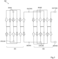
- FIG. 5 represents, very schematically, a coupler 500 according to one embodiment.
- the coupler 500 comprises two assemblies 501 and 502 of the type of the assembly 400 described in relation to the figure 4 .
- the assemblies 501 and 502 are connected "in series".
- the output terminal OUT501 of the assembly 501 is connected, preferably connected, to the input terminal IN502 of the assembly 502
- the output terminal ISO501 of the assembly 501 is connected, preferably connected, to the input terminal CPL502 of the assembly 502.
- FIGS. 6 and 7 represent top views of practical examples of implementation of the coupler 500 described in relation to the figure 5 . More specifically, the figure 6 represents a 600 coupler, and the figure 7 represents a 700 coupler.
- the difference between the couplers 600 and 700 is that the coupler 700 has zigzag-shaped coils while the coupler 600 has generally rectangular-shaped coils. These coils have the advantage of improving the coupling performance of the coupler 700. Indeed, when the unit elements of the assemblies of the coupler 700 are folded in a zigzag, the advantageous couplings, i.e. the couplings desired by the coupler, are increased, and the disadvantageous couplings, i.e. the couplings to be avoided are reduced.
Landscapes
- Coils Or Transformers For Communication (AREA)
Applications Claiming Priority (1)
| Application Number | Priority Date | Filing Date | Title |
|---|---|---|---|
| FR2308118A FR3151713A1 (fr) | 2023-07-27 | 2023-07-27 | Coupleur hybride à quatre-vingt-dix degrés |
Publications (1)
| Publication Number | Publication Date |
|---|---|
| EP4498511A1 true EP4498511A1 (de) | 2025-01-29 |
Family
ID=89157908
Family Applications (1)
| Application Number | Title | Priority Date | Filing Date |
|---|---|---|---|
| EP24190971.2A Pending EP4498511A1 (de) | 2023-07-27 | 2024-07-25 | Vier-vingt-dix-hybridkoppler |
Country Status (3)
| Country | Link |
|---|---|
| US (1) | US20250038391A1 (de) |
| EP (1) | EP4498511A1 (de) |
| FR (1) | FR3151713A1 (de) |
Citations (3)
| Publication number | Priority date | Publication date | Assignee | Title |
|---|---|---|---|---|
| JPS56110303A (en) * | 1980-02-05 | 1981-09-01 | Nec Corp | Cross-type hybrid circuit |
| EP1208615A1 (de) * | 1999-08-27 | 2002-05-29 | Allgon AB | Viertorhybrid |
| CN104767022A (zh) * | 2014-01-22 | 2015-07-08 | 南京米乐为微电子科技有限公司 | 新型超宽频90°集成耦合器 |
Family Cites Families (2)
| Publication number | Priority date | Publication date | Assignee | Title |
|---|---|---|---|---|
| WO2018011476A1 (fr) * | 2016-07-12 | 2018-01-18 | Stmicroelectronics Sa | Dispositif de couplage intégré, en particulier du type hybride 90° |
| EP4208746A1 (de) * | 2020-09-03 | 2023-07-12 | Telefonaktiebolaget LM Ericsson (publ) | Hochfrequenzschnittstelle für leiterplatte zu leiterplatte |
-
2023
- 2023-07-27 FR FR2308118A patent/FR3151713A1/fr active Pending
-
2024
- 2024-07-25 EP EP24190971.2A patent/EP4498511A1/de active Pending
- 2024-07-26 US US18/785,654 patent/US20250038391A1/en active Pending
Patent Citations (3)
| Publication number | Priority date | Publication date | Assignee | Title |
|---|---|---|---|---|
| JPS56110303A (en) * | 1980-02-05 | 1981-09-01 | Nec Corp | Cross-type hybrid circuit |
| EP1208615A1 (de) * | 1999-08-27 | 2002-05-29 | Allgon AB | Viertorhybrid |
| CN104767022A (zh) * | 2014-01-22 | 2015-07-08 | 南京米乐为微电子科技有限公司 | 新型超宽频90°集成耦合器 |
Non-Patent Citations (1)
| Title |
|---|
| TABARANI FILIPE ET AL: "Compact monolithic spiral quadrature coupler design", 2017 13TH CONFERENCE ON PH.D. RESEARCH IN MICROELECTRONICS AND ELECTRONICS (PRIME), IEEE, 12 June 2017 (2017-06-12), pages 181 - 184, XP033119697, DOI: 10.1109/PRIME.2017.7974137 * |
Also Published As
| Publication number | Publication date |
|---|---|
| US20250038391A1 (en) | 2025-01-30 |
| FR3151713A1 (fr) | 2025-01-31 |
Similar Documents
| Publication | Publication Date | Title |
|---|---|---|
| EP1601101B1 (de) | BALUN Transformator und Tiefpassfilter | |
| EP1659686B1 (de) | Balun mit diskreten Bauelementen | |
| EP2184801B1 (de) | Differentialfiltervorrichtung mit koplanar gekoppelten Resonatoren und Filterantenne mit einer entsprechenden Vorrichtung | |
| EP2345104A1 (de) | Differenz-dipolantennensystem mit einer koplanaren strahlungsstruktur und sender-/empfängereinrichtung | |
| FR2877163A1 (fr) | Reglage du rapport d'impedances d'un balun | |
| FR2894062A1 (fr) | Balun a rapport d'impedances 1/4 | |
| EP2184803A1 (de) | Vorrichtung zur Abdichtung eines Öffnungsfeldes eines Kraftfahrzeugs mit Hilfe eines Schiebepaneels, und entsprechendes Kraftfahrzeug | |
| EP0852846B1 (de) | Oberflächenfilter unter verwendung der kopplung zwischen drei akustischen spuren | |
| FR2476898A1 (fr) | Bobinage electromagnetique comportant des elements discrets et dispositif d'alimentation electrique comportant de tels bobinages | |
| EP1953775B1 (de) | Induktivität auf mehreren Stufen | |
| EP0660512A1 (de) | Phasenschiebverstärker und seine Verwendung in einer Zusammenführungsschaltung | |
| FR2916570A1 (fr) | Structure inductive plane | |
| EP2774211A1 (de) | Vorrichtung zur emv-filterung auf einer leiterplatte | |
| EP0387954B1 (de) | Bandpassfilter mit einstellbarer Bandbreite | |
| EP4498511A1 (de) | Vier-vingt-dix-hybridkoppler | |
| EP2396884B1 (de) | Filterungsnetz in der hr-si-siliziumtechnologie | |
| FR3004024A1 (fr) | Dispositif de transmission sans fil d'energie par induction a un recepteur | |
| CA2027885C (fr) | Cellule de filtrage et filtre correspondant | |
| FR3077432A1 (fr) | Filtre de mode commun | |
| TW201249102A (en) | Filter | |
| EP2507865B1 (de) | Kompakter planarer vhf/uhf-leistungsimpedanztransformator | |
| WO2017140661A1 (fr) | Procede d'interconnexion chip on chip miniaturisee d'un module electronique 3d | |
| EP3678151A1 (de) | Mehrphasiger induktiver filter | |
| WO2022018114A1 (fr) | Ensemble comprenant au moins une premiere et une deuxieme inductance en couplage magnetique partiel | |
| FR3065144A1 (fr) | Filtre radiofrequence et procede de fabrication associe |
Legal Events
| Date | Code | Title | Description |
|---|---|---|---|
| PUAI | Public reference made under article 153(3) epc to a published international application that has entered the european phase |
Free format text: ORIGINAL CODE: 0009012 |
|
| STAA | Information on the status of an ep patent application or granted ep patent |
Free format text: STATUS: REQUEST FOR EXAMINATION WAS MADE |
|
| 17P | Request for examination filed |
Effective date: 20240725 |
|
| AK | Designated contracting states |
Kind code of ref document: A1 Designated state(s): AL AT BE BG CH CY CZ DE DK EE ES FI FR GB GR HR HU IE IS IT LI LT LU LV MC ME MK MT NL NO PL PT RO RS SE SI SK SM TR |