EP4498359A1 - Sound source system, method, and program - Google Patents
Sound source system, method, and program Download PDFInfo
- Publication number
- EP4498359A1 EP4498359A1 EP23774346.3A EP23774346A EP4498359A1 EP 4498359 A1 EP4498359 A1 EP 4498359A1 EP 23774346 A EP23774346 A EP 23774346A EP 4498359 A1 EP4498359 A1 EP 4498359A1
- Authority
- EP
- European Patent Office
- Prior art keywords
- sound source
- cores
- data
- sound
- signal
- Prior art date
- Legal status (The legal status is an assumption and is not a legal conclusion. Google has not performed a legal analysis and makes no representation as to the accuracy of the status listed.)
- Pending
Links
Images



Classifications
-
- G—PHYSICS
- G10—MUSICAL INSTRUMENTS; ACOUSTICS
- G10H—ELECTROPHONIC MUSICAL INSTRUMENTS; INSTRUMENTS IN WHICH THE TONES ARE GENERATED BY ELECTROMECHANICAL MEANS OR ELECTRONIC GENERATORS, OR IN WHICH THE TONES ARE SYNTHESISED FROM A DATA STORE
- G10H1/00—Details of electrophonic musical instruments
- G10H1/0091—Means for obtaining special acoustic effects
-
- G—PHYSICS
- G10—MUSICAL INSTRUMENTS; ACOUSTICS
- G10H—ELECTROPHONIC MUSICAL INSTRUMENTS; INSTRUMENTS IN WHICH THE TONES ARE GENERATED BY ELECTROMECHANICAL MEANS OR ELECTRONIC GENERATORS, OR IN WHICH THE TONES ARE SYNTHESISED FROM A DATA STORE
- G10H1/00—Details of electrophonic musical instruments
- G10H1/0033—Recording/reproducing or transmission of music for electrophonic musical instruments
-
- G—PHYSICS
- G10—MUSICAL INSTRUMENTS; ACOUSTICS
- G10H—ELECTROPHONIC MUSICAL INSTRUMENTS; INSTRUMENTS IN WHICH THE TONES ARE GENERATED BY ELECTROMECHANICAL MEANS OR ELECTRONIC GENERATORS, OR IN WHICH THE TONES ARE SYNTHESISED FROM A DATA STORE
- G10H1/00—Details of electrophonic musical instruments
- G10H1/18—Selecting circuits
- G10H1/183—Channel-assigning means for polyphonic instruments
- G10H1/187—Channel-assigning means for polyphonic instruments using multiplexed channel processors
-
- G—PHYSICS
- G10—MUSICAL INSTRUMENTS; ACOUSTICS
- G10H—ELECTROPHONIC MUSICAL INSTRUMENTS; INSTRUMENTS IN WHICH THE TONES ARE GENERATED BY ELECTROMECHANICAL MEANS OR ELECTRONIC GENERATORS, OR IN WHICH THE TONES ARE SYNTHESISED FROM A DATA STORE
- G10H7/00—Instruments in which the tones are synthesised from a data store, e.g. computer organs
- G10H7/002—Instruments in which the tones are synthesised from a data store, e.g. computer organs using a common processing for different operations or calculations, and a set of microinstructions, e.g. programs, to control the sequence thereof
- G10H7/004—Instruments in which the tones are synthesised from a data store, e.g. computer organs using a common processing for different operations or calculations, and a set of microinstructions, e.g. programs, to control the sequence thereof with one or more auxiliary processor in addition to the main processing unit
-
- G—PHYSICS
- G10—MUSICAL INSTRUMENTS; ACOUSTICS
- G10H—ELECTROPHONIC MUSICAL INSTRUMENTS; INSTRUMENTS IN WHICH THE TONES ARE GENERATED BY ELECTROMECHANICAL MEANS OR ELECTRONIC GENERATORS, OR IN WHICH THE TONES ARE SYNTHESISED FROM A DATA STORE
- G10H2210/00—Aspects or methods of musical processing having intrinsic musical character, i.e. involving musical theory or musical parameters or relying on musical knowledge, as applied in electrophonic musical tools or instruments
- G10H2210/155—Musical effects
- G10H2210/245—Ensemble, i.e. adding one or more voices, also instrumental voices
- G10H2210/251—Chorus, i.e. automatic generation of two or more extra voices added to the melody, e.g. by a chorus effect processor or multiple voice harmonizer, to produce a chorus or unison effect, wherein individual sounds from multiple sources with roughly the same timbre converge and are perceived as one
-
- G—PHYSICS
- G10—MUSICAL INSTRUMENTS; ACOUSTICS
- G10H—ELECTROPHONIC MUSICAL INSTRUMENTS; INSTRUMENTS IN WHICH THE TONES ARE GENERATED BY ELECTROMECHANICAL MEANS OR ELECTRONIC GENERATORS, OR IN WHICH THE TONES ARE SYNTHESISED FROM A DATA STORE
- G10H2210/00—Aspects or methods of musical processing having intrinsic musical character, i.e. involving musical theory or musical parameters or relying on musical knowledge, as applied in electrophonic musical tools or instruments
- G10H2210/155—Musical effects
- G10H2210/265—Acoustic effect simulation, i.e. volume, spatial, resonance or reverberation effects added to a musical sound, usually by appropriate filtering or delays
- G10H2210/281—Reverberation or echo
-
- G—PHYSICS
- G10—MUSICAL INSTRUMENTS; ACOUSTICS
- G10H—ELECTROPHONIC MUSICAL INSTRUMENTS; INSTRUMENTS IN WHICH THE TONES ARE GENERATED BY ELECTROMECHANICAL MEANS OR ELECTRONIC GENERATORS, OR IN WHICH THE TONES ARE SYNTHESISED FROM A DATA STORE
- G10H2210/00—Aspects or methods of musical processing having intrinsic musical character, i.e. involving musical theory or musical parameters or relying on musical knowledge, as applied in electrophonic musical tools or instruments
- G10H2210/375—Tempo or beat alterations; Music timing control
-
- G—PHYSICS
- G10—MUSICAL INSTRUMENTS; ACOUSTICS
- G10H—ELECTROPHONIC MUSICAL INSTRUMENTS; INSTRUMENTS IN WHICH THE TONES ARE GENERATED BY ELECTROMECHANICAL MEANS OR ELECTRONIC GENERATORS, OR IN WHICH THE TONES ARE SYNTHESISED FROM A DATA STORE
- G10H2240/00—Data organisation or data communication aspects, specifically adapted for electrophonic musical tools or instruments
- G10H2240/171—Transmission of musical instrument data, control or status information; Transmission, remote access or control of music data for electrophonic musical instruments
- G10H2240/201—Physical layer or hardware aspects of transmission to or from an electrophonic musical instrument, e.g. voltage levels, bit streams, code words or symbols over a physical link connecting network nodes or instruments
- G10H2240/205—Synchronous transmission of an analog or digital signal, e.g. according to a specific intrinsic timing, or according to a separate clock
-
- G—PHYSICS
- G10—MUSICAL INSTRUMENTS; ACOUSTICS
- G10H—ELECTROPHONIC MUSICAL INSTRUMENTS; INSTRUMENTS IN WHICH THE TONES ARE GENERATED BY ELECTROMECHANICAL MEANS OR ELECTRONIC GENERATORS, OR IN WHICH THE TONES ARE SYNTHESISED FROM A DATA STORE
- G10H2240/00—Data organisation or data communication aspects, specifically adapted for electrophonic musical tools or instruments
- G10H2240/325—Synchronizing two or more audio tracks or files according to musical features or musical timings
Definitions
- the disclosure of the present specification relates to a sound source system, a method, and a program.
- Patent Literature 1 describes a specific configuration of this type of sound source system.
- the sound source system described in Patent Literature 1 mixes digital musical sound data output from a plurality of sound source cores by a mixer, applies effect processing to the mixed digital musical sound data, adds the digital musical sound data subjected to the effect processing, converts the digital musical sound data into an analog signal, and outputs the analog signal.
- Patent Literature 1 JP H7-129161 A
- the sound source System described in Patent Literature 1 has a configuration in which the effect processing and the like are performed on the digital musical sound data output from the plurality of sound source cores connected in parallel by a circuit at the subsequent stage of the sound source core.
- a configuration for example, it is not possible to adopt a configuration in which a signal of one sound source core is input to the other sound source core and sound is further processed using a digital signal processor (DSP) resource of the other sound source core.
- DSP digital signal processor
- the present invention has been made in view of the above circumstances, and an object thereof is to provide a sound source system, a method, and a program capable of sharing DSP resources among a plurality of sound source cores without increasing a circuit scale.
- a sound source system includes: a plurality of sound source cores that process musical sound data; a phase control unit that aligns phases of clocks defining an input/output timing of the musical sound data with respect to a sound source core among the plurality of sound source cores; and a connection control unit that controls connection among the plurality of sound source cores such that musical sound data in which phases of the clocks are aligned is transferred among the plurality of sound source cores.
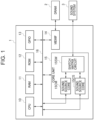
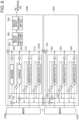
- Fig. 1 is a block diagram illustrating a configuration of a sound source system 1 according to an embodiment of the present invention.
- the sound source system 1 is configured as, for example, a large scale integration (LSI), and is built in an electronic musical instrument such as an electronic keyboard.
- the sound source system 1 is not limited to an electronic musical instrument, and may be built in a smartphone, a personal computer (PC), a tablet terminal, a portable game machine, a feature phone, a personal digital assistant (PDA), or the like.
- LSI large scale integration
- PDA personal digital assistant
- the sound source system 1 includes a central processing unit (CPU) 10, a random access memory (RAM) 11, and a read only memory (ROM) 12, a general purpose input/output (GPIO) 13, a memory interface (MEMIF) 14, and a core unit 15.
- CPU central processing unit
- RAM random access memory
- ROM read only memory
- GPIO general purpose input/output
- MEMIF memory interface
- Each unit of the sound source system 1 is connected via a bus 16.
- Each unit of the sound source system 1 operates with a basic operation clock supplied from a clock generator (not illustrated).
- the CPU 10 reads a program and data stored in the ROM 12 and uses the RAM 11 as a work area to integrally control the sound source system 1. That is, when the CPU 10 executes the program, the sound source system 1 operates.
- the CPU 10 is, for example, a single processor or a multiprocessor, and includes at least one processor. In the case of a configuration including a plurality of processors, the CPU 10 may be packaged as a single device, or may be configured by a plurality of devices physically separated in the sound source system 1.
- the RAM 11 is, for example, a static random access memory (SRAM), and operates at a higher speed than a dynamic random access memory (DRAM) 2 to be described later. Therefore, the RAM 11 temporarily holds data and programs in processing requiring high-speed operation.
- the RAM 11 holds programs and data read from the ROM 12 and other data necessary for communication.
- the RAM 11 operates as a shared memory shared among a plurality of sound source cores.
- the ROM 12 is a nonvolatile semiconductor memory such as a flash memory, an erasable programmable ROM (EPROM), or an electrically erasable programmable ROM (EEPROM).
- the ROM 12 stores programs and data used by the CPU 10 to perform various processing.
- the ROM 12 stores, for example, waveform data for each key number for each timbre (Guitars, bass, piano, and the like).
- the GPIO 13 is a general-purpose port mounted on the sound source system 1 which is an LSI.
- a musical instrument digital interface (MIDI) device (not illustrated) is connected to the GPIO 13.
- MIDI data an example of standard MIDI file (SMF) data
- SMS standard MIDI file
- the MEMIF 14 is, for example, an interface connected to the external DRAM 2.
- the DRAM 2 is slower in reading and writing data than the SRAM, but generally has a large capacity. Therefore, the DRAM 2 stores data that does not require high-speed processing or data with a large capacity, for example, SMF data. In this case, the SMF data is input from the DRAM 2 via the MEMIF 14.
- the music data input via the GPIO 13 or the MEMIF 14 is not limited to the SMF data, and may be music data conforming to another standard.
- the core unit 15 includes two sound source cores 15CM and 15CS and a switch matrix circuit 15SW.
- the sound source core 15CM and the sound source core 15CS have the same circuit structure. Note that, in a case where the sound source core 15CM and the sound source core 15CS are collectively described, each is referred to as a "sound source core 15C".
- the core unit 15 outputs the digital musical sound data generated by each sound source core 15C to a sound system 3 in the I 2 S format via the switch matrix circuit 15SW. Note that the number of sound source cores 15C included in the core unit 15 is not limited to two, and may be three or more.
- the sound system 3 includes a D/A converter, an amplifier, a speaker, and the like.
- the sound system 3 converts digital musical sound data input in the I 2 S format into an analog signal, amplifies the converted analog signal with the amplifier, and outputs the amplified analog signal from the speaker. Therefore, for example, a musical sound corresponding to the MIDI data is reproduced.
- the sound system 3 may include input means such as an A/D converter and a microphone.
- input means such as an A/D converter and a microphone.
- a singing voice input from the microphone may be converted into digital data by the A/D converter, then the digital data may be input to the core unit 15, and an effect may be added to the singing voice.
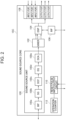
- Fig. 2 is a block diagram illustrating a configuration of the sound source core 15C that processes digital musical sound data.
- two sound source cores 15C having the same structure are included, and it is not necessary to prepare a plurality of types of sound source cores 15C having different structures. Therefore, the sound source system 1 can be reduced in cost, and the sound source core 15C can be easily managed.
- the sound source core 15C includes an n-channel (for example, 128 channels) sound source unit 100, a mixer 102, a DSP 104, a BIF 106, an I 2 S interface 108, a reset pulse input/output circuit 110, and an operation counter 112.
- the sound source unit 100 includes a bus interface (BIF) 100a, a sound generator (SG) 100b, a digital controlled filter (DCF) 100c, an equalizer (EQ) 100d, and a digital controlled amplifier (DCA) 100e.
- BIF bus interface
- SG sound generator
- DCF digital controlled filter
- EQ equalizer
- DCA digital controlled amplifier
- the BIF 100a is an interface connected to each unit of the sound source system 1 via the bus 16.
- the CPU 10 instructs the sound source core 15C to read the corresponding waveform data from among the plurality of waveform data stored in the ROM 12 according to the MIDI data input to the GPIO 13.
- This instruction signal is input to the SG 100b via the BIF 100a.
- the SG 100b reads waveform data from the ROM 12 in accordance with an instruction signal from the CPU 10, and generates digital musical sound data on the basis of the read waveform data. Since the sound source core 15C includes the 128-channel sound source unit 100, it is possible to simultaneously perform sound production processing of up to 128 musical sounds.
- the digital musical sound data generated by the SG 100b is output to the mixer 102 through the digital filter processing by the DCF 100c, the equalizer processing by the EQ 100d, and the amplification processing by the DCA 100e.
- the mixer 102 mixes digital musical sound data of up to 128 musical sounds input from the sound source unit 100 and outputs the digital musical sound data to the DSP 104.
- the DSP 104 performs effect processing on the digital musical sound data input from the mixer 102 and outputs the digital musical sound data to the I 2 S interface 108. Furthermore, the DSP 104 is connected to each unit of the sound source system 1 via the BIF 106.
- the I 2 S interface 108 is an interface for transferring the digital musical sound data in the I 2 S format between the DSPs 104 of the sound source cores 15C or between the DSP 104 and the switch matrix circuit 15SW.
- the digital musical sound data transferred in the I 2 S format is referred to as "I 2 S data”.
- the I 2 S data includes a BCK signal, an LRCK signal, and a DATA signal.
- the BCK signal is a clock for latching the DATA signal which is serial data at a rising edge, and may be referred to as a bit clock.
- the LRCK signal discriminates between the L channel and the R channel of the digital musical sound data and indicates the position of the most significant bit of the DATA signal, and is sometimes referred to as a word clock.
- the DATA signal is a signal of a bit string of musical sound data, and includes a most significant bit MSB and a least significant bit LSB.
- the I 2 S interface 108 includes three input ports and three output ports.
- the I 2 S interface 108 inputs and outputs the I 2 S data via each port. Note that each of the number of input ports and the number of output ports included in the I 2 S interface 108 is not limited to three. Each of the number of input ports and the number of output ports may be two or less, or may be four or more.
- Fig. 3 is a block diagram mainly illustrating a configuration of a reset pulse input/output circuit (control signal output unit) 110.
- the CPU 10 outputs an instruction signal instructing issuance of a reset pulse to the reset pulse input/output circuit 110 at a predetermined timing (for example, when the sound source system 1 is activated, or when the operation of the sound source core 15CS in the stopped state is restarted as described later).
- the reset pulse input/output circuit 110 generates a reset pulse (reset signal), which is an example of a trigger signal, in accordance with an instruction signal from the CPU 10, and outputs the generated reset pulse to the operation counter (value generation unit) 112.
- the reset pulse input/output circuit 110 includes a setting register (setting unit) 110a, an edge detection unit 110b, and an OR circuit (logical OR circuit or control signal output circuit) 110c.
- a setting register setting unit
- an edge detection unit 110b edge detection unit
- an OR circuit logical OR circuit or control signal output circuit
- one input terminal T1 is connected to the edge detection unit 110b, and the other input terminal T2 is connected to the other sound source core 15C.
- the input to the input terminal T2 is fixed to "0". Therefore, the OR circuit 110c outputs an output signal corresponding to the reset pulse from the edge detection unit 110b to the operation counter 112 only when the reset pulse from the edge detection unit 110b is input to the input terminal T1.
- the operation counter 112 is, for example, a timing generator, and always generates a value mc serving as an operation reference of the sound source core 15C during the operation of the sound source system 1.
- the value mc is used to generate, for example, a BCK signal and an LRCK signal which are clocks.
- the logic circuit mounted on the I 2 S interface 108 generates the BCK signal and the LRCK signal based on the value mc generated by the operation counter 112.
- the values mc of the operation counters 112 of the sound source cores 15C are synchronized (substantially matched). Therefore, the phases of the BCK signal and the LRCK signal generated based on the value mc are aligned between the two sound source cores 15C.
- the fact that the phases are aligned means that, for example, even in a case where the clock waveform is rounded or deformed due to a factor such as a capacity between wirings, or in a case where the clock is slightly shifted between the sound source cores 15C due to a delay, it is sufficient that the high section of the clock waveform of one sound source core 15C and the high section of the clock waveform of the other sound source core 15C substantially coincide with each other, and the low section of the clock waveform of one sound source core 15C and the low section of the clock waveform of the other sound source core 15C substantially coincide with each other.
- the CPU 10 instructs all the sound source cores 15C to issue reset pulses.
- the CPU 10 instructs only the sound source core 15CM set as a master to issue the reset pulse.
- the reset pulse input/output circuit 110 of the sound source core 15CM outputs the reset pulse not only to the operation counter 112 but also to the other sound source core 15CS set as a slave.
- the OR circuit 110c of the sound source core 15CM In the OR circuit 110c of the sound source core 15CM, the input to the input terminal T2 is fixed to "0", similarly to Operation Example 1. Therefore, as in Operation Example 1, the OR circuit 110c of the sound source core 15CM outputs the reset pulse from the edge detection unit 110b to the operation counter 112 only when the reset pulse is input to the input terminal T1.
- the input to the input terminal T2 is not fixed in the OR circuit 110c of the sound source core 15CS. Furthermore, since the reset pulse is not generated in the sound source core 15CS, there is no input to the input terminal T1. Therefore, only when the reset pulse from the sound source core 15CM is input to the input terminal T2, the OR circuit 110c of the sound source core 15CS outputs the reset pulse to the operation counter 112.
- the value mc is simultaneously reset to "0" in each sound source core 15C only by instructing the sound source core 15CM to issue the reset pulse, and the phases of the BCK signal and the LRCK signal are aligned between the two sound source cores 15C.
- the sound source cores 15C having the same structure can be used in either case of Operation Examples 1 and 2, it is not necessary to separately prepare and incorporate a plurality of types of sound source cores 15C.
- the CPU 10 operates as a phase control unit that supplies a reset pulse, which is an example of a trigger signal, to each of the plurality of sound source cores 15C by executing the program stored in the ROM 12.
- a reset pulse which is an example of a trigger signal
- the value mc of the operation counter 112 is synchronized among the plurality of sound source cores 15C, and each of the plurality of sound source cores 15C generates the BCK signal and the LRCK signal which are examples of the clock based on the value mc of the operation counter 112 in the synchronized state.
- the CPU 10 operating as a phase control unit aligns the phases of the clocks (the BCK signal and the LRCK signal) that define the input/output timing of the digital musical sound data with respect to the sound source core 15C among the plurality of sound source cores 15C.
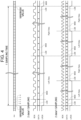
- Fig. 4 is a diagram illustrating a timing chart of the I 2 S data.
- a transfer example in which data of two channels is transferred by one sampling and a faster transfer example in which data of four channels is transferred by one sampling are also illustrated.
- the L-channel data and the R-channel data are sequentially transferred during one sampling.
- the L-channel data, the R-channel data, the L-channel data, and the R-channel data are sequentially transferred during one sampling.
- the BCK signal and the LRCK signal are generated on the basis of the value mc illustrated at the top in Fig. 4 .
- the transfer format of the digital musical sound data is not limited to the I 2 S format, and may be another format such as left justified or right justified.
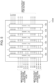
- Fig. 5 is a block diagram illustrating a configuration of the switch matrix circuit 15SW connectable to each of the plurality of sound source cores 15C.
- the switch matrix circuit 15SW includes six selector switches 150 to 155.
- the selector switches 150 to 155 are a 9-to-1 selector switch and is a 1-bit selector switch.
- the switch matrix circuit 15SW There are nine inputs in the switch matrix circuit 15SW. Specifically, there are inputs from three output ports provided in the I 2 S interfaces 108 of the two sound source cores 15C (total of six inputs: IN1 to IN6) and inputs from the outside (for example, the sound system 3) (total of three inputs: IN7 to IN9). Furthermore, the switch matrix circuit 15SW includes six systems as systems for distribution output. Specifically, there are outputs to three input ports included in the I 2 S interfaces 108 of the two sound source cores 15C (total of six distribution outputs: OUT1 to OUT6). Note that, in the switch matrix circuit 15SW, the input from the sound source core 15C is through-output to the outside. Therefore, the switch matrix circuit 15SW includes six 9-to-1 selector switches.
- LR signal digital musical sound data
- two LR signals of the sound source core 15CS are input to the sound source core 15CM.
- bit 4 that is, IN4 is selected in selector switch 150 to connect IN4 and OUT1.
- bit 5 that is, IN5 is selected in the selector switch 151, IN5 and OUT2 are connected. Therefore, the L signal and the R signal input from the sound source core 15CS to IN4 and IN5 are output from OUT1 and OUT2, respectively, and are input to the sound source core 15CM.
- an external input signal is input to the sound source core 15CS.
- bit 7, that is, IN7 is selected in the selector switch 155 to connect IN7 and OUT6. Therefore, the external input signal input from the outside to IN7 is output from OUT6 and input to the sound source core 15CS.
- various operation patterns of the switch matrix circuit 15SW can be set. For example, an operation pattern for transferring the I 2 S data from the sound source core 15CS to the sound source core 15CM can be set, and an operation pattern for transferring the I 2 S data from the sound source core 15CM to the sound source core 15CS can be set.
- the same switch matrix circuit 15SW can be used in both a case where the switch matrix circuit is mounted on a product adopting the former operation pattern and a case where the switch matrix circuit is mounted on a product adopting the latter operation pattern. Since the same switch matrix circuit 15SW can be used in different products, for example, cost reduction is achieved.
- each of the selector switches 150 to 155 needs to be configured by a 3-bit selector switch.
- the phases of the BCK signal and the LRCK signal can be aligned between the two sound source cores 15C. Therefore, it is not necessary to provide a switch matrix for the BCK signal and the LRCK signal in the I 2 S data.
- Each of the selector switches 150 to 155 may be configured by a 1-bit selector switch for the DATA signal, so that the circuit scale of the switch matrix circuit 15SW can be suppressed to be small. In other words, since the signal whose connection is controlled by the switch matrix circuit 15SW does not include the signal of the clock (the BCK signal and the LRCK signal), the circuit scale of the switch matrix circuit 15SW is suppressed to be small.
- Fig. 6 is a diagram illustrating an example of effect processing by the DSP 104.
- the mixer 102 and the DSP 104 included in the sound source core 15CM are referred to as a "mixer 102M” and a “DSP 104M”, respectively
- the mixer 102 and the DSP 104 included in the sound source core 15CS are referred to as a "mixer 102S” and a “DSP 104S", respectively.
- the DSP 104M includes system effect processing units 202 and 204 and master effect processing units 206 and 208 to be described later, whereas the DSP 104S does not include the system effect processing units 202 and 204 and the master effect processing units 206 and 208. However, since these processing units are set by software, the DSP 104M and the DSP 104S are the same in terms of hardware circuit structure.
- the DSP 104M includes system effect processing units 202 and 204, master effect processing units 206 and 208, insertion effect processing units 210 and 212, and adders 220, 222, and 224.
- the DSP 104S includes insertion effect processing units 302, 304, and 306 and adders 320, 322, and 324.
- the system effect processing units 202 and 204 apply a system effect (for example, an effect such as a reverb which is generally connected to a send return terminal and is applied to the entire musical sound in terms of a background sound) shared by the sound source cores 15C. Therefore, the system effect processing units 202 and 204 are connected not only to the mixer 102M of the DSP 104M but also to the DSP 104S.
- a system effect for example, an effect such as a reverb which is generally connected to a send return terminal and is applied to the entire musical sound in terms of a background sound
- the amplifier for the output signal to the left side (mixer 102M or 102S side) in Fig. 6 functions as a send volume of the signal to be input to the system effect processing units 202 and 204.
- the amplifiers for the output signals to the right side in Fig. 6 function as return volumes of the return signals from the system effect processing units 202 and 204, respectively.
- the chorus that is the system effect processing unit 204 in the present embodiment can also function as an insertion effect.
- the send volume to the system effect processing unit 202 of the same processing unit may be set to "0"
- the send volume of each of the insertion effect processing units 210, 212, 302, 304, and 306 to the system effect processing unit 204 may be set to "0".
- the adder 220 arranged at the preceding stage of the system effect processing unit 202 adds the digital musical sound data (waveform data for reverb processing) output from the mixer 102M, the system effect processing unit 204, and the insertion effect processing units 210 and 212, and further adds the digital musical sound data (more specifically, the waveform data for the reverb processing output from the insertion effect processing units 302, 304, and 306 and added by the adder 320) output from the DSP 104S.
- the system effect processing unit 202 generates a reverb musical sound using the waveform data input from the adder 220 and outputs the waveform data of the generated reverb musical sound.
- the adder 222 arranged at the preceding stage of the system effect processing unit 204 adds the digital musical sound data (waveform data for chorus processing) output from the mixer 102M, and the insertion effect processing units 210 and 212, and further adds the digital musical sound data (more specifically, the waveform data for the chorus processing output from the insertion effect processing units 302, 304, and 306 and added by the adder 322) output from the DSP 104S.
- the system effect processing unit 204 generates a chorus musical sound using the waveform data input from the adder 222 and outputs the waveform data of the generated chorus musical sound.
- the master effect processing units 206 and 208 apply the master effect shared by the sound source cores 15C at the subsequent stages of the system effect processing units and the insertion effect processing units. Therefore, the master effect processing units 206 and 208 are connected to the system effect processing units, the insertion effect processing units, and the mixer 102M.
- the adder 224 disposed at the preceding stage of the master effect processing unit 206 adds the waveform data output from the mixer 102M, the system effect processing units 202 and 204, and the insertion effect processing units 210 and 212, and further adds the waveform data (more specifically, the waveform data output from the mixer 102S and the insertion effect processing units 302, 304, and 306 and added by the adder 324) output from the DSP 104S.
- the master effect processing unit 206 performs compressor processing on the digital musical sound data obtained by the addition by the adder 224.
- the master effect processing unit 208 performs equalizer processing on the digital musical sound data subjected to the compressor processing by the master effect processing unit 206.
- the digital musical sound data after the equalizer processing is output to the sound system 3 via the I 2 S interface 108.
- the master effect processing units 206 and 208 play a role of adjusting the volume difference and adjusting the frequency characteristics in the final output stage of the musical sound so as to adjust the entire musical sound. Therefore, for a direct sound that does not pass through a system effect, it is desirable that the latency be minimized, and a signal in a state in which phases are aligned as much as possible among the plurality of sound source cores 15C be added by the adder 224 and input to the master effect processing unit 206.
- the insertion effect processing units 210 and 212 apply an insertion effect only to the digital musical sound data input from the mixer 102M. That is, the insertion effect processing units 210 and 212 apply an effect that is not shared by the sound source cores 15C. For example, the insertion effect processing unit 210 and the insertion effect processing unit 212 apply mutually different insertion effects (for example, a flanger and a phaser).
- the insertion effect processing units 302, 304, and 306 apply an insertion effect only to the digital musical sound data input from the mixer 102S. That is, the insertion effect processing units 302, 304, and 306 also apply mutually different effects that are not shared by the sound source cores 15C.
- the output signals of the insertion effect processing units 210, 212, 302, 304, and 306 face the left side (mixer 102M or 102S side) in Fig. 6 and are divided into a signal passing through the system effect and a signal of direct sound that faces the right side in Fig. 6 and does not pass through the system effect.
- the direct sound desirably has a lower latency than a background sound that passes through a system effect such as a reverb or a chorus.
- the digital musical sound data generated by the sound source core 15CS is transferred to the sound source core 15CM via the switch matrix circuit 15SW or via the shared memory.
- Fig. 7A illustrates latency in a case where the digital musical sound data is transferred via the switch matrix circuit 15SW.
- Fig. 7B illustrates latency in a case where the digital musical sound data is transferred via the shared memory.
- the RAM 11 (SRAM) having a small single access latency is used as a shared memory.
- the I 2 S data is written to the register of the DSP 104S, the written I 2 S data is transferred, and the transferred I 2 S data is written to the register of the DSP 104M. Therefore, the digital musical sound data generated by the sound source core 15CS is delayed by about 2 samplings with respect to the digital musical sound data generated by the sound source core 15CM.
- the shared memory area is secured, the digital musical sound data is written in the secured shared memory area, the written digital musical sound data is read from the shared memory area, and the read digital musical sound data is written in the cache memory of the DSP 104M. Therefore, the digital musical sound data generated by the sound source core 15CS is delayed by about 3 samplings with respect to the digital musical sound data generated by the sound source core 15CM.
- the digital musical sound data generated by the sound source core 15CS may be delayed more greatly than the digital musical sound data generated by the sound source core 15CM.
- the latency can be suppressed to be small as compared with a case where the digital musical sound data is transferred via the shared memory.
- the direct sound from each insertion effect is desirably lower in latency than the sound passing through the system effect. Therefore, under the control of the CPU 10, the digital musical sound data output from the insertion effect processing units 302, 304, and 306 of the mixer 102S and the DSP 104S, that is, the waveform data after addition by the adder 324 is transferred from the sound source core 15CS to the master effect processing unit 206 via a path with low latency, that is, via the switch matrix circuit 15SW.
- the number of input/output paths is limited in paths via the switch matrix circuit 15SW. In a case where the number of input/output paths is increased, the number of input/output of the switch matrix circuit 15SW is increased, and the circuit scale of the switch matrix circuit 15SW is increased.
- a ring buffer is formed on the RAM 11 via the shared memory, the number of paths that can be transferred is almost unlimited. Furthermore, by increasing the size of the ring buffer, the amount of transfer data per one path can be increased. However, in this case, the latency until the written data is read increases. Furthermore, as described above, the reverb processing and the chorus processing by the system effect processing units 202 and 204 may have somewhat higher latency than the insertion effect processing.
- the digital musical sound data output from the insertion effect processing units 302, 304, and 306 of the DSP 104S that is, the waveform data after addition by the adder 320 is transferred from the sound source core 15CS to the system effect processing unit 202 via the shared memory. Furthermore, under the control of the CPU 10, the digital musical sound data output from the insertion effect processing units 302, 304, and 306 of the DSP 104S, that is, the waveform data after addition by the adder 322 is transferred from the sound source core 15CS to the system effect processing unit 204 via the shared memory.
- the switch matrix circuit 15SW and the shared memory in combination, it is possible to transfer a large amount of data during one sampling while suppressing the circuit scale of the switch matrix circuit 15SW to be small.
- processing example illustrated in Fig. 6 is merely an example.
- a configuration in which the reverb, the chorus, the compressor, and the equalizer are not shared and a configuration in which the non-shared insertion effect is shared in the present embodiment are also within the scope of the present invention.
- a configuration for performing another effect processing not illustrated in Fig. 6 is also within the scope of the present invention.
- the CPU 10 executes the program stored in the ROM 12 to operate as a connection control unit that controls the connection among the plurality of sound source cores 15C such that the digital musical sound data in which the phases of the clocks (the BCK signal and the LRCK signal) are aligned is transferred among the plurality of sound source cores 15C. More specifically, the CPU 10 operating as a connection control unit controls the connection among the plurality of sound source cores 15C via the switch matrix circuit 15SW.
- one sound source core 15CM in the plurality of sound source cores 15C performs the first effect processing and the second effect processing on the first musical sound data and the second musical sound data from each of the plurality of sound source cores 15C.
- the first musical sound data is digital musical sound data to which the first effect processing (for example, insertion effect processing) in which an allowable value for latency at the time of transfer is smaller than that of the second effect processing (for example, reverb processing and chorus processing) is applied, and is transferred in the I 2 S format among the plurality of sound source cores 15C.
- the second musical sound data is digital musical sound data to which the second effect processing having a larger allowable value for latency at the time of transfer than that of the first effect processing is applied, and is transferred among the plurality of sound source cores 15C via the shared memory.
- the first effect processing is processing requiring a lower latency at the time of transferring musical sound data than the second effect processing.
- each of the selector switches 150 to 155 can be configured with the 1-bit selector switch even in the configuration in which the effect is shared among the plurality of sound source cores 15C, and the circuit scale of the switch matrix circuit 15SW can be suppressed to be small.
- the present invention is not limited to the above-described embodiments, and various modifications can be made in the implementation stage without departing from the gist thereof.
- the functions executed in the above-described embodiments may be appropriately combined and implemented as much as possible.
- the above-described embodiments include various stages, and various inventions can be extracted by appropriate combinations of a plurality of disclosed constituent elements. For example, even if some components are deleted from all the components shown in the embodiment, if an effect can be obtained, a configuration from which the components are deleted can be extracted as an invention.
- Fig. 8 is a diagram illustrating an example of effect processing by the DSP 104 according to a first modification of the present invention.
- a delay circuit 230 is arranged at a stage subsequent to the system effect processing units 202 and 204 and the insertion effect processing units 210 and 212.
- the delay circuit 230 delays the input waveform data by, for example, 2 samplings.
- the waveform data delayed by the delay circuit 230 and the waveform data from the mixer 102M are added by the adder 226, and the added data is further added to the waveform data transferred from the sound source core 15CS via the switch matrix circuit 15SW by the adder 224 so as to be input to the master effect processing unit 206.
- the master effect processing unit 206 receives digital musical sound data in which a phase difference between the digital musical sound data generated by the sound source core 15CS (waveform data passing via the switch matrix circuit 15SW) and the digital musical sound data generated by the sound source core 15CM (waveform data not passing via the switch matrix circuit 15SW) is suppressed.
- the sound source core 15CM includes the delay circuit 230 (an example of the phase difference suppression unit) that suppresses the phase difference of the musical sound data from each of the plurality of sound source cores 15C.
- the method of performing the synchronization control of the operation counters 112 among the plurality of sound source cores 15C is not limited to the method using the reset pulse.
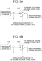
- Figs. 9A and 9B are diagrams corresponding to the sound source core 15CM and the sound source core 15CS, respectively, and are block diagrams illustrating configurations of a switch 110' and the operation counter 112 according to a second modification of the present invention.
- the sound source system 1 according to the second modification includes the configurations illustrated in Figs. 9A and 9B instead of the configuration illustrated in Fig. 3 .
- the CPU 10 outputs a master enable signal having a value of 1 to the sound source core 15CM set as a master, and outputs a master enable signal having a value of 0 to the sound source core 15CS set as a slave.
- the master enable signal is a control signal for the switch 110'.
- the switch 110' is connected to a contact T11 according to the master enable signal. Therefore, the operation counter 112 of the sound source core 15CM and the inside of the sound source core 15CM (supply destination of the value mc) are connected, and the connection between the operation counter 112 of the sound source core 15CS and the inside of the sound source core 15CM is cut off.
- the switch 110' is connected to a contact T12 according to the master enable signal. Therefore, the connection between the operation counter 112 of the sound source core 15CS and the inside of the sound source core 15CS (supply destination of the value mc) is cut off, and the operation counter 112 of the sound source core 15CM and the inside of the sound source core 15CS are connected.
- the value mc generated by the operation counter 112 of the sound source core 15CM is supplied to the inside of the sound source core 15CM and to the inside of the sound source core 15CS. Since the common value mc is supplied to the two sound source cores 15C, the phases of the BCK signal and the LRCK signal generated based on the value mc are aligned between the two sound source cores 15C.
- the supply of the basic operation clock to at least one sound source core 15C may be stopped according to the sound production state of the musical sound (in other words, depending on the processing situation of the musical sound data).
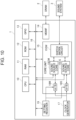
- Fig. 10 is a block diagram illustrating a configuration of a sound source system 1 according to a third modification of the present invention.
- Fig. 10 illustrates a clock generator 17 that supplies the basic operation clock to each unit of the sound source system 1.
- the clock generator 17 is an example of a basic operation clock supply unit that supplies a basic operation clock for operating the plurality of sound source cores 15C.
- a clock gating switch 18M is disposed between the clock generator 17 and the sound source core 15CM. Furthermore, a clock gating switch 18S is disposed between the clock generator 17 and the sound source core 15CS.
- the CPU 10 writes a value in a setting register 19 according to the sound production state of the musical sound. For example, when the value 1 is written for the sound source core 15CM, an enable signal of the value 1 is output from the setting register 19 to the clock gating switch 18M. Therefore, the clock gating switch 18M connects the clock generator 17 and the sound source core 15CM, and the basic operation clock is supplied from the clock generator 17 to the sound source core 15CM. When the value 0 is written for the sound source core 15CM, an enable signal of the value 0 is output from the setting register 19 to the clock gating switch 18M. Therefore, the clock gating switch 18M cuts off the connection between the clock generator 17 and the sound source core 15CM, and the supply of the basic operation clock from the clock generator 17 to the sound source core 15CM is stopped. Therefore, the sound source core 15CM stops.
- connection and interruption of the connection between the clock generator 17 and the sound source core 15CS are performed by the clock gating switch 18S in a similar operation.
- the basic operation clock is supplied from the clock generator 17 to the sound source core 15CS.
- the supply of the basic operation clock from the clock generator 17 to the sound source core 15CS is stopped, so that the sound source core 15CS is stopped.
- the CPU 10 executes the program stored in the ROM 12 to operate as a supply control unit that controls the supply and stop of the supply of the basic operation clock to each of the plurality of sound source cores 15C by the clock generator 17 (an example of the basic operation clock supply unit) according to the processing situation of the digital musical sound data.
- the sound source core 15CM supplies the value mc to the sound source core 15CS.
- the sound source core 15CS is stopped. Only when the number of stoppable sound source cores 15C becomes 2, the sound source core 15CM is also stopped.
- a reset pulse is supplied to each sound source core 15C when the operation of the sound source core 15CS is restarted. Therefore, also in this case, the phases of the BCK signal and the LRCK signal are aligned between the two sound source cores 15C even after the operation is restarted.
Landscapes
- Engineering & Computer Science (AREA)
- Physics & Mathematics (AREA)
- Acoustics & Sound (AREA)
- Multimedia (AREA)
- General Engineering & Computer Science (AREA)
- Electrophonic Musical Instruments (AREA)
Abstract
Description
- The disclosure of the present specification relates to a sound source system, a method, and a program.
- A sound source system including a plurality of sound source cores is known. For example,
Patent Literature 1 describes a specific configuration of this type of sound source system. - The sound source system described in
Patent Literature 1 mixes digital musical sound data output from a plurality of sound source cores by a mixer, applies effect processing to the mixed digital musical sound data, adds the digital musical sound data subjected to the effect processing, converts the digital musical sound data into an analog signal, and outputs the analog signal. - Patent Literature 1:
JP H7-129161 A - As described above, the sound source System described in
Patent Literature 1 has a configuration in which the effect processing and the like are performed on the digital musical sound data output from the plurality of sound source cores connected in parallel by a circuit at the subsequent stage of the sound source core. However, in such a configuration, for example, it is not possible to adopt a configuration in which a signal of one sound source core is input to the other sound source core and sound is further processed using a digital signal processor (DSP) resource of the other sound source core. Furthermore, in a case where the DSP resources of the plurality of sound source cores can be shared between the sound source cores, there is a possibility that the circuit scale of the sound source system increases. - The present invention has been made in view of the above circumstances, and an object thereof is to provide a sound source system, a method, and a program capable of sharing DSP resources among a plurality of sound source cores without increasing a circuit scale.
- A sound source system according to an embodiment of the present invention includes: a plurality of sound source cores that process musical sound data; a phase control unit that aligns phases of clocks defining an input/output timing of the musical sound data with respect to a sound source core among the plurality of sound source cores; and a connection control unit that controls connection among the plurality of sound source cores such that musical sound data in which phases of the clocks are aligned is transferred among the plurality of sound source cores.
- According to the embodiment of the present invention, it is possible to provide a sound source system, a method, and a program capable of sharing DSP resources among a plurality of sound source cores without increasing a circuit scale.
-
-
Fig. 1 is a block diagram illustrating a configuration of a sound source system according to an embodiment of the present invention. -
Fig. 2 is a block diagram illustrating a configuration of a sound source core included in a sound source system according to an embodiment of the present invention. -
Fig. 3 is a block diagram illustrating a configuration of a reset pulse input/output circuit provided in a sound source core according to an embodiment of the present invention. -
Fig. 4 is a diagram illustrating a timing chart of inter-IC sound interface (I2S) data. -
Fig. 5 is a block diagram illustrating a configuration of a switch matrix circuit included in a sound source system according to an embodiment of the present invention. -
Fig. 6 is a diagram illustrating an example of effect processing by a DSP provided in a sound source system according to an embodiment of the present invention. -
Fig. 7A is a diagram illustrating latency in a case where digital musical sound data is transferred in an I2S format according to an embodiment of the present invention. -
Fig. 7B is a diagram illustrating latency in a case where digital musical sound data is transferred via a shared memory in an embodiment of the present invention. -
Fig. 8 is a diagram illustrating an example of effect processing by a DSP provided in a sound source system according to a first modification of the present invention. -
Fig. 9A is a block diagram illustrating a configuration for performing synchronization control of an operation counter according to a second modification of the present invention. -
Fig. 9B is a block diagram illustrating a configuration for performing synchronization control of the operation counter according to the second modification of the present invention. -
Fig. 10 is a block diagram illustrating a configuration of a sound source system according to a third modification of the present invention. - A sound source system, a method, and a program according to an embodiment of the present invention will be described in detail with reference to the drawings.
-
Fig. 1 is a block diagram illustrating a configuration of asound source system 1 according to an embodiment of the present invention. Thesound source system 1 is configured as, for example, a large scale integration (LSI), and is built in an electronic musical instrument such as an electronic keyboard. Thesound source system 1 is not limited to an electronic musical instrument, and may be built in a smartphone, a personal computer (PC), a tablet terminal, a portable game machine, a feature phone, a personal digital assistant (PDA), or the like. - As illustrated in
Fig. 1 , thesound source system 1 includes a central processing unit (CPU) 10, a random access memory (RAM) 11, and a read only memory (ROM) 12, a general purpose input/output (GPIO) 13, a memory interface (MEMIF) 14, and acore unit 15. Each unit of thesound source system 1 is connected via abus 16. Each unit of thesound source system 1 operates with a basic operation clock supplied from a clock generator (not illustrated). - The
CPU 10 reads a program and data stored in theROM 12 and uses theRAM 11 as a work area to integrally control thesound source system 1. That is, when theCPU 10 executes the program, thesound source system 1 operates. - The
CPU 10 is, for example, a single processor or a multiprocessor, and includes at least one processor. In the case of a configuration including a plurality of processors, theCPU 10 may be packaged as a single device, or may be configured by a plurality of devices physically separated in thesound source system 1. - The
RAM 11 is, for example, a static random access memory (SRAM), and operates at a higher speed than a dynamic random access memory (DRAM) 2 to be described later. Therefore, theRAM 11 temporarily holds data and programs in processing requiring high-speed operation. TheRAM 11 holds programs and data read from theROM 12 and other data necessary for communication. - Furthermore, as will be described later, the
RAM 11 operates as a shared memory shared among a plurality of sound source cores. - The
ROM 12 is a nonvolatile semiconductor memory such as a flash memory, an erasable programmable ROM (EPROM), or an electrically erasable programmable ROM (EEPROM). TheROM 12 stores programs and data used by theCPU 10 to perform various processing. - In addition, the
ROM 12 stores, for example, waveform data for each key number for each timbre (Guitars, bass, piano, and the like). - The
GPIO 13 is a general-purpose port mounted on thesound source system 1 which is an LSI. For example, a musical instrument digital interface (MIDI) device (not illustrated) is connected to theGPIO 13. In this case, MIDI data (an example of standard MIDI file (SMF) data) conforming to the MIDI standard is input from the MIDI device via theGPIO 13. - The MEMIF 14 is, for example, an interface connected to the
external DRAM 2. TheDRAM 2 is slower in reading and writing data than the SRAM, but generally has a large capacity. Therefore, theDRAM 2 stores data that does not require high-speed processing or data with a large capacity, for example, SMF data. In this case, the SMF data is input from theDRAM 2 via the MEMIF 14. - The music data input via the
GPIO 13 or the MEMIF 14 is not limited to the SMF data, and may be music data conforming to another standard. - The
core unit 15 includes two sound source cores 15CM and 15CS and a switch matrix circuit 15SW. In the present embodiment, the sound source core 15CM and the sound source core 15CS have the same circuit structure. Note that, in a case where the sound source core 15CM and the sound source core 15CS are collectively described, each is referred to as a "sound source core 15C". - The
core unit 15 outputs the digital musical sound data generated by eachsound source core 15C to asound system 3 in the I2S format via the switch matrix circuit 15SW. Note that the number ofsound source cores 15C included in thecore unit 15 is not limited to two, and may be three or more. - The
sound system 3 includes a D/A converter, an amplifier, a speaker, and the like. Thesound system 3 converts digital musical sound data input in the I2S format into an analog signal, amplifies the converted analog signal with the amplifier, and outputs the amplified analog signal from the speaker. Therefore, for example, a musical sound corresponding to the MIDI data is reproduced. - Furthermore, the
sound system 3 may include input means such as an A/D converter and a microphone. For example, a singing voice input from the microphone may be converted into digital data by the A/D converter, then the digital data may be input to thecore unit 15, and an effect may be added to the singing voice. -
Fig. 2 is a block diagram illustrating a configuration of thesound source core 15C that processes digital musical sound data. In the present embodiment, twosound source cores 15C having the same structure are included, and it is not necessary to prepare a plurality of types ofsound source cores 15C having different structures. Therefore, thesound source system 1 can be reduced in cost, and thesound source core 15C can be easily managed. - The
sound source core 15C includes an n-channel (for example, 128 channels)sound source unit 100, amixer 102, aDSP 104, aBIF 106, an I2S interface 108, a reset pulse input/output circuit 110, and anoperation counter 112. - The
sound source unit 100 includes a bus interface (BIF) 100a, a sound generator (SG) 100b, a digital controlled filter (DCF) 100c, an equalizer (EQ) 100d, and a digital controlled amplifier (DCA) 100e. - The
BIF 100a is an interface connected to each unit of thesound source system 1 via thebus 16. For example, theCPU 10 instructs thesound source core 15C to read the corresponding waveform data from among the plurality of waveform data stored in theROM 12 according to the MIDI data input to theGPIO 13. This instruction signal is input to theSG 100b via theBIF 100a. - The
SG 100b reads waveform data from theROM 12 in accordance with an instruction signal from theCPU 10, and generates digital musical sound data on the basis of the read waveform data. Since thesound source core 15C includes the 128-channelsound source unit 100, it is possible to simultaneously perform sound production processing of up to 128 musical sounds. - The digital musical sound data generated by the
SG 100b is output to themixer 102 through the digital filter processing by theDCF 100c, the equalizer processing by theEQ 100d, and the amplification processing by theDCA 100e. - The
mixer 102 mixes digital musical sound data of up to 128 musical sounds input from thesound source unit 100 and outputs the digital musical sound data to theDSP 104. - The
DSP 104 performs effect processing on the digital musical sound data input from themixer 102 and outputs the digital musical sound data to the I2S interface 108. Furthermore, theDSP 104 is connected to each unit of thesound source system 1 via theBIF 106. - The I2S interface 108 is an interface for transferring the digital musical sound data in the I2S format between the
DSPs 104 of thesound source cores 15C or between theDSP 104 and the switch matrix circuit 15SW. For convenience, the digital musical sound data transferred in the I2S format is referred to as "I2S data". - The I2S data includes a BCK signal, an LRCK signal, and a DATA signal. The BCK signal is a clock for latching the DATA signal which is serial data at a rising edge, and may be referred to as a bit clock. The LRCK signal discriminates between the L channel and the R channel of the digital musical sound data and indicates the position of the most significant bit of the DATA signal, and is sometimes referred to as a word clock. The DATA signal is a signal of a bit string of musical sound data, and includes a most significant bit MSB and a least significant bit LSB.
- The I2S interface 108 includes three input ports and three output ports. The I2S interface 108 inputs and outputs the I2S data via each port. Note that each of the number of input ports and the number of output ports included in the I2S interface 108 is not limited to three. Each of the number of input ports and the number of output ports may be two or less, or may be four or more.
-
Fig. 3 is a block diagram mainly illustrating a configuration of a reset pulse input/output circuit (control signal output unit) 110. TheCPU 10 outputs an instruction signal instructing issuance of a reset pulse to the reset pulse input/output circuit 110 at a predetermined timing (for example, when thesound source system 1 is activated, or when the operation of the sound source core 15CS in the stopped state is restarted as described later). The reset pulse input/output circuit 110 generates a reset pulse (reset signal), which is an example of a trigger signal, in accordance with an instruction signal from theCPU 10, and outputs the generated reset pulse to the operation counter (value generation unit) 112. - As illustrated in
Fig. 3 , the reset pulse input/output circuit 110 includes a setting register (setting unit) 110a, anedge detection unit 110b, and an OR circuit (logical OR circuit or control signal output circuit) 110c. Here, Operation Examples 1 and 2 of the reset pulse input/output circuit 110 will be described. - In Operation Example 1, when the reset pulse input/
output circuit 110 receives an instruction signal of reset pulse issuance from theCPU 10, thesetting register 110a modulates the setting value from "0" to "1". Theedge detection unit 110b detects a rising edge of a signal when the setting value in thesetting register 110a is modulated from "0" to "1" to generate a reset pulse according to the edge, and outputs the generated reset pulse to theOR circuit 110c. - In the
OR circuit 110c, one input terminal T1 is connected to theedge detection unit 110b, and the other input terminal T2 is connected to the othersound source core 15C. However, in Operation Example 1, the input to the input terminal T2 is fixed to "0". Therefore, theOR circuit 110c outputs an output signal corresponding to the reset pulse from theedge detection unit 110b to theoperation counter 112 only when the reset pulse from theedge detection unit 110b is input to the input terminal T1. - The
operation counter 112 is, for example, a timing generator, and always generates a value mc serving as an operation reference of thesound source core 15C during the operation of thesound source system 1. The value mc is used to generate, for example, a BCK signal and an LRCK signal which are clocks. For example, the logic circuit mounted on the I2S interface 108 generates the BCK signal and the LRCK signal based on the value mc generated by theoperation counter 112. - When a reset pulse is input from the reset pulse input/
output circuit 110 to theoperation counter 112, the value mc generated by theoperation counter 112 is reset to "0". - That is, when the instruction signal of the reset pulse issuance by the
CPU 10 is input to eachsound source core 15C, the value mc is simultaneously reset to "0" in eachsound source core 15C. After the value mc is reset, the counting-up of the value mc is simultaneously restarted in eachsound source core 15C. - Therefore, the values mc of the operation counters 112 of the
sound source cores 15C are synchronized (substantially matched). Therefore, the phases of the BCK signal and the LRCK signal generated based on the value mc are aligned between the twosound source cores 15C. - There is an individual difference in the
operation counter 112 of eachsound source core 15C. Therefore, strictly speaking, the BCK signal and the LRCK signal are not in synchronization but in a state in which the phases are aligned. However, since the individual difference of theoperation counter 112 is small, it is substantially acceptable to describe that "the BCK signal and the LRCK signal are synchronized between the twosound source cores 15C". Here, the fact that the phases are aligned means that, for example, even in a case where the clock waveform is rounded or deformed due to a factor such as a capacity between wirings, or in a case where the clock is slightly shifted between thesound source cores 15C due to a delay, it is sufficient that the high section of the clock waveform of onesound source core 15C and the high section of the clock waveform of the othersound source core 15C substantially coincide with each other, and the low section of the clock waveform of onesound source core 15C and the low section of the clock waveform of the othersound source core 15C substantially coincide with each other. - Furthermore, since the plurality of operation counters 112 operate in synchronization, fan-out of one
operation counter 112 is reduced. - In Operation Example 1, the
CPU 10 instructs all thesound source cores 15C to issue reset pulses. On the other hand, in Operation Example 2, theCPU 10 instructs only the sound source core 15CM set as a master to issue the reset pulse. - In Operation Example 2, the reset pulse input/
output circuit 110 of the sound source core 15CM outputs the reset pulse not only to theoperation counter 112 but also to the other sound source core 15CS set as a slave. - In the
OR circuit 110c of the sound source core 15CM, the input to the input terminal T2 is fixed to "0", similarly to Operation Example 1. Therefore, as in Operation Example 1, theOR circuit 110c of the sound source core 15CM outputs the reset pulse from theedge detection unit 110b to theoperation counter 112 only when the reset pulse is input to the input terminal T1. - On the other hand, the input to the input terminal T2 is not fixed in the
OR circuit 110c of the sound source core 15CS. Furthermore, since the reset pulse is not generated in the sound source core 15CS, there is no input to the input terminal T1. Therefore, only when the reset pulse from the sound source core 15CM is input to the input terminal T2, theOR circuit 110c of the sound source core 15CS outputs the reset pulse to theoperation counter 112. - In Operation Example 2, the value mc is simultaneously reset to "0" in each
sound source core 15C only by instructing the sound source core 15CM to issue the reset pulse, and the phases of the BCK signal and the LRCK signal are aligned between the twosound source cores 15C. - Since the
sound source cores 15C having the same structure can be used in either case of Operation Examples 1 and 2, it is not necessary to separately prepare and incorporate a plurality of types ofsound source cores 15C. - As described above, the
CPU 10 operates as a phase control unit that supplies a reset pulse, which is an example of a trigger signal, to each of the plurality ofsound source cores 15C by executing the program stored in theROM 12. When the reset pulse is supplied to each of the plurality ofsound source cores 15C, the value mc of theoperation counter 112 is synchronized among the plurality ofsound source cores 15C, and each of the plurality ofsound source cores 15C generates the BCK signal and the LRCK signal which are examples of the clock based on the value mc of theoperation counter 112 in the synchronized state. That is, theCPU 10 operating as a phase control unit aligns the phases of the clocks (the BCK signal and the LRCK signal) that define the input/output timing of the digital musical sound data with respect to thesound source core 15C among the plurality ofsound source cores 15C. -
Fig. 4 is a diagram illustrating a timing chart of the I2S data. InFig. 4 , a transfer example in which data of two channels is transferred by one sampling and a faster transfer example in which data of four channels is transferred by one sampling are also illustrated. In the former transfer example, the L-channel data and the R-channel data are sequentially transferred during one sampling. In the latter transfer example, the L-channel data, the R-channel data, the L-channel data, and the R-channel data are sequentially transferred during one sampling. - In any transfer example, the BCK signal and the LRCK signal are generated on the basis of the value mc illustrated at the top in
Fig. 4 . - Note that a configuration for transferring data of more channels during one sampling, such as 8, 16, and 32 channels, is also within the scope of the present invention.
- Furthermore, the transfer format of the digital musical sound data is not limited to the I2S format, and may be another format such as left justified or right justified.
-
Fig. 5 is a block diagram illustrating a configuration of the switch matrix circuit 15SW connectable to each of the plurality ofsound source cores 15C. As illustrated inFig. 5 , the switch matrix circuit 15SW includes sixselector switches 150 to 155. The selector switches 150 to 155 are a 9-to-1 selector switch and is a 1-bit selector switch. - There are nine inputs in the switch matrix circuit 15SW. Specifically, there are inputs from three output ports provided in the I2S interfaces 108 of the two
sound source cores 15C (total of six inputs: IN1 to IN6) and inputs from the outside (for example, the sound system 3) (total of three inputs: IN7 to IN9). Furthermore, the switch matrix circuit 15SW includes six systems as systems for distribution output. Specifically, there are outputs to three input ports included in the I2S interfaces 108 of the twosound source cores 15C (total of six distribution outputs: OUT1 to OUT6). Note that, in the switch matrix circuit 15SW, the input from thesound source core 15C is through-output to the outside. Therefore, the switch matrix circuit 15SW includes six 9-to-1 selector switches. - For example, in order to process the LR signal (digital musical sound data) of the sound source core 15CS in the sound source core 15CM, a case is considered in which two LR signals of the sound source core 15CS are input to the sound source core 15CM. In this case, for example,
bit 4, that is, IN4 is selected inselector switch 150 to connect IN4 and OUT1. Similarly, when bit 5, that is, IN5 is selected in theselector switch 151, IN5 and OUT2 are connected. Therefore, the L signal and the R signal input from the sound source core 15CS to IN4 and IN5 are output from OUT1 and OUT2, respectively, and are input to the sound source core 15CM. - As another example, a case where an external input signal is input to the sound source core 15CS will be considered. In this case, for example, bit 7, that is, IN7 is selected in the
selector switch 155 to connect IN7 and OUT6. Therefore, the external input signal input from the outside to IN7 is output from OUT6 and input to the sound source core 15CS. - With the configuration of the switch matrix circuit 15SW in this manner, various operation patterns of the switch matrix circuit 15SW can be set. For example, an operation pattern for transferring the I2S data from the sound source core 15CS to the sound source core 15CM can be set, and an operation pattern for transferring the I2S data from the sound source core 15CM to the sound source core 15CS can be set.
- The same switch matrix circuit 15SW can be used in both a case where the switch matrix circuit is mounted on a product adopting the former operation pattern and a case where the switch matrix circuit is mounted on a product adopting the latter operation pattern. Since the same switch matrix circuit 15SW can be used in different products, for example, cost reduction is achieved.
- Conventionally, for example, a case where the I2S data is transferred between two
sound source cores 15C in a state where the phases of the BCK signal and the LRCK signal are not aligned between the twosound source cores 15C is considered. In this case, it is necessary to provide a switch matrix for all of the BCK signal, the LRCK signal, and the DATA signal in the I2S data. Therefore, each of the selector switches 150 to 155 needs to be configured by a 3-bit selector switch. - On the other hand, in the present embodiment, as described above, the phases of the BCK signal and the LRCK signal can be aligned between the two
sound source cores 15C. Therefore, it is not necessary to provide a switch matrix for the BCK signal and the LRCK signal in the I2S data. Each of the selector switches 150 to 155 may be configured by a 1-bit selector switch for the DATA signal, so that the circuit scale of the switch matrix circuit 15SW can be suppressed to be small. In other words, since the signal whose connection is controlled by the switch matrix circuit 15SW does not include the signal of the clock (the BCK signal and the LRCK signal), the circuit scale of the switch matrix circuit 15SW is suppressed to be small. -
Fig. 6 is a diagram illustrating an example of effect processing by theDSP 104. InFig. 6 , among themixers 102 and theDSPs 104 illustrated inFig. 2 , themixer 102 and theDSP 104 included in the sound source core 15CM are referred to as a "mixer 102M" and a "DSP 104M", respectively, and themixer 102 and theDSP 104 included in the sound source core 15CS are referred to as a "mixer 102S" and a "DSP 104S", respectively. Note that theDSP 104M includes systemeffect processing units effect processing units DSP 104S does not include the systemeffect processing units effect processing units DSP 104M and theDSP 104S are the same in terms of hardware circuit structure. - As illustrated in
Fig. 6 , theDSP 104M includes systemeffect processing units effect processing units effect processing units adders DSP 104S includes insertioneffect processing units adders - The system
effect processing units sound source cores 15C. Therefore, the systemeffect processing units mixer 102M of theDSP 104M but also to theDSP 104S. - Here, in the insertion
effect processing units effect processing unit 204, the amplifier for the output signal to the left side (mixer Fig. 6 functions as a send volume of the signal to be input to the systemeffect processing units - On the other hand, in the system
effect processing units Fig. 6 function as return volumes of the return signals from the systemeffect processing units effect processing unit 204 in the present embodiment can also function as an insertion effect. In a case where the chorus of the systemeffect processing unit 204 is caused to function as an insertion effect, the send volume to the systemeffect processing unit 202 of the same processing unit may be set to "0", and the send volume of each of the insertioneffect processing units effect processing unit 204 may be set to "0". - The
adder 220 arranged at the preceding stage of the systemeffect processing unit 202 adds the digital musical sound data (waveform data for reverb processing) output from themixer 102M, the systemeffect processing unit 204, and the insertioneffect processing units effect processing units DSP 104S. The systemeffect processing unit 202 generates a reverb musical sound using the waveform data input from theadder 220 and outputs the waveform data of the generated reverb musical sound. - The
adder 222 arranged at the preceding stage of the systemeffect processing unit 204 adds the digital musical sound data (waveform data for chorus processing) output from themixer 102M, and the insertioneffect processing units effect processing units DSP 104S. The systemeffect processing unit 204 generates a chorus musical sound using the waveform data input from theadder 222 and outputs the waveform data of the generated chorus musical sound. - The master
effect processing units sound source cores 15C at the subsequent stages of the system effect processing units and the insertion effect processing units. Therefore, the mastereffect processing units mixer 102M. - The
adder 224 disposed at the preceding stage of the mastereffect processing unit 206 adds the waveform data output from themixer 102M, the systemeffect processing units effect processing units mixer 102S and the insertioneffect processing units DSP 104S. - The master
effect processing unit 206 performs compressor processing on the digital musical sound data obtained by the addition by theadder 224. The mastereffect processing unit 208 performs equalizer processing on the digital musical sound data subjected to the compressor processing by the mastereffect processing unit 206. The digital musical sound data after the equalizer processing is output to thesound system 3 via the I2S interface 108. - The master
effect processing units sound source cores 15C be added by theadder 224 and input to the mastereffect processing unit 206. - The insertion
effect processing units mixer 102M. That is, the insertioneffect processing units sound source cores 15C. For example, the insertioneffect processing unit 210 and the insertioneffect processing unit 212 apply mutually different insertion effects (for example, a flanger and a phaser). - The insertion
effect processing units mixer 102S. That is, the insertioneffect processing units sound source cores 15C. - The output signals of the insertion
effect processing units mixer Fig. 6 and are divided into a signal passing through the system effect and a signal of direct sound that faces the right side inFig. 6 and does not pass through the system effect. The direct sound desirably has a lower latency than a background sound that passes through a system effect such as a reverb or a chorus. - In the present embodiment, the digital musical sound data generated by the sound source core 15CS is transferred to the sound source core 15CM via the switch matrix circuit 15SW or via the shared memory. Here,
Fig. 7A illustrates latency in a case where the digital musical sound data is transferred via the switch matrix circuit 15SW. Furthermore,Fig. 7B illustrates latency in a case where the digital musical sound data is transferred via the shared memory. - In the present embodiment, the RAM 11 (SRAM) having a small single access latency is used as a shared memory.
- As illustrated in
Fig. 7A , in a case where data passes via the switch matrix circuit 15SW, the I2S data is written to the register of theDSP 104S, the written I2S data is transferred, and the transferred I2S data is written to the register of theDSP 104M. Therefore, the digital musical sound data generated by the sound source core 15CS is delayed by about 2 samplings with respect to the digital musical sound data generated by the sound source core 15CM. - As illustrated in
Fig. 7B , in a case where data passes via the shared memory, the shared memory area is secured, the digital musical sound data is written in the secured shared memory area, the written digital musical sound data is read from the shared memory area, and the read digital musical sound data is written in the cache memory of theDSP 104M. Therefore, the digital musical sound data generated by the sound source core 15CS is delayed by about 3 samplings with respect to the digital musical sound data generated by the sound source core 15CM. - Note that there is a sufficient possibility that the write latency and the read latency in the shared memory become larger depending on the operation status of the
RAM 11. Therefore, the digital musical sound data generated by the sound source core 15CS may be delayed more greatly than the digital musical sound data generated by the sound source core 15CM. - That is, in a case where the digital musical sound data is transferred via the switch matrix circuit 15SW, the latency can be suppressed to be small as compared with a case where the digital musical sound data is transferred via the shared memory.
- As described above, the direct sound from each insertion effect is desirably lower in latency than the sound passing through the system effect. Therefore, under the control of the
CPU 10, the digital musical sound data output from the insertioneffect processing units mixer 102S and theDSP 104S, that is, the waveform data after addition by theadder 324 is transferred from the sound source core 15CS to the mastereffect processing unit 206 via a path with low latency, that is, via the switch matrix circuit 15SW. - However, the number of input/output paths is limited in paths via the switch matrix circuit 15SW. In a case where the number of input/output paths is increased, the number of input/output of the switch matrix circuit 15SW is increased, and the circuit scale of the switch matrix circuit 15SW is increased.
- On the other hand, if a ring buffer is formed on the
RAM 11 via the shared memory, the number of paths that can be transferred is almost unlimited. Furthermore, by increasing the size of the ring buffer, the amount of transfer data per one path can be increased. However, in this case, the latency until the written data is read increases. Furthermore, as described above, the reverb processing and the chorus processing by the systemeffect processing units - Therefore, in the present embodiment, under the control of the
CPU 10, the digital musical sound data output from the insertioneffect processing units DSP 104S, that is, the waveform data after addition by theadder 320 is transferred from the sound source core 15CS to the systemeffect processing unit 202 via the shared memory. Furthermore, under the control of theCPU 10, the digital musical sound data output from the insertioneffect processing units DSP 104S, that is, the waveform data after addition by theadder 322 is transferred from the sound source core 15CS to the systemeffect processing unit 204 via the shared memory. - As described above, in the present embodiment, by using the switch matrix circuit 15SW and the shared memory in combination, it is possible to transfer a large amount of data during one sampling while suppressing the circuit scale of the switch matrix circuit 15SW to be small.
- Note that the processing example illustrated in
Fig. 6 is merely an example. A configuration in which the reverb, the chorus, the compressor, and the equalizer are not shared and a configuration in which the non-shared insertion effect is shared in the present embodiment are also within the scope of the present invention. Furthermore, a configuration for performing another effect processing not illustrated inFig. 6 is also within the scope of the present invention. - As described above, the
CPU 10 executes the program stored in theROM 12 to operate as a connection control unit that controls the connection among the plurality ofsound source cores 15C such that the digital musical sound data in which the phases of the clocks (the BCK signal and the LRCK signal) are aligned is transferred among the plurality ofsound source cores 15C. More specifically, theCPU 10 operating as a connection control unit controls the connection among the plurality ofsound source cores 15C via the switch matrix circuit 15SW. - Furthermore, one sound source core 15CM in the plurality of
sound source cores 15C performs the first effect processing and the second effect processing on the first musical sound data and the second musical sound data from each of the plurality ofsound source cores 15C. The first musical sound data is digital musical sound data to which the first effect processing (for example, insertion effect processing) in which an allowable value for latency at the time of transfer is smaller than that of the second effect processing (for example, reverb processing and chorus processing) is applied, and is transferred in the I2S format among the plurality ofsound source cores 15C. The second musical sound data is digital musical sound data to which the second effect processing having a larger allowable value for latency at the time of transfer than that of the first effect processing is applied, and is transferred among the plurality ofsound source cores 15C via the shared memory. In addition, it can be said that the first effect processing is processing requiring a lower latency at the time of transferring musical sound data than the second effect processing. - As described above, in the present embodiment, since the phases of the BCK signal and the LRCK signal are aligned among the plurality of
sound source cores 15C, each of the selector switches 150 to 155 can be configured with the 1-bit selector switch even in the configuration in which the effect is shared among the plurality ofsound source cores 15C, and the circuit scale of the switch matrix circuit 15SW can be suppressed to be small. - In addition, the present invention is not limited to the above-described embodiments, and various modifications can be made in the implementation stage without departing from the gist thereof. Furthermore, the functions executed in the above-described embodiments may be appropriately combined and implemented as much as possible. The above-described embodiments include various stages, and various inventions can be extracted by appropriate combinations of a plurality of disclosed constituent elements. For example, even if some components are deleted from all the components shown in the embodiment, if an effect can be obtained, a configuration from which the components are deleted can be extracted as an invention.
-
Fig. 8 is a diagram illustrating an example of effect processing by theDSP 104 according to a first modification of the present invention. - As described above, the digital musical sound data generated by the sound source core 15CS has latency at the time of transfer, and thus is delayed with respect to the digital musical sound data generated by the sound source core 15CM. Therefore, in the first modification, a
delay circuit 230 is arranged at a stage subsequent to the systemeffect processing units effect processing units delay circuit 230 delays the input waveform data by, for example, 2 samplings. - The waveform data delayed by the
delay circuit 230 and the waveform data from themixer 102M are added by theadder 226, and the added data is further added to the waveform data transferred from the sound source core 15CS via the switch matrix circuit 15SW by theadder 224 so as to be input to the mastereffect processing unit 206. - That is, in the first modification, the master
effect processing unit 206 receives digital musical sound data in which a phase difference between the digital musical sound data generated by the sound source core 15CS (waveform data passing via the switch matrix circuit 15SW) and the digital musical sound data generated by the sound source core 15CM (waveform data not passing via the switch matrix circuit 15SW) is suppressed. - As described above, the sound source core 15CM includes the delay circuit 230 (an example of the phase difference suppression unit) that suppresses the phase difference of the musical sound data from each of the plurality of
sound source cores 15C. - The method of performing the synchronization control of the operation counters 112 among the plurality of
sound source cores 15C is not limited to the method using the reset pulse. -
Figs. 9A and 9B are diagrams corresponding to the sound source core 15CM and the sound source core 15CS, respectively, and are block diagrams illustrating configurations of a switch 110' and theoperation counter 112 according to a second modification of the present invention. Thesound source system 1 according to the second modification includes the configurations illustrated inFigs. 9A and 9B instead of the configuration illustrated inFig. 3 . - The
CPU 10 outputs a master enable signal having a value of 1 to the sound source core 15CM set as a master, and outputs a master enable signal having a value of 0 to the sound source core 15CS set as a slave. The master enable signal is a control signal for the switch 110'. - As illustrated in
Fig. 9A , in the sound source core 15CM, the switch 110' is connected to a contact T11 according to the master enable signal. Therefore, theoperation counter 112 of the sound source core 15CM and the inside of the sound source core 15CM (supply destination of the value mc) are connected, and the connection between theoperation counter 112 of the sound source core 15CS and the inside of the sound source core 15CM is cut off. - Furthermore, as illustrated in
Fig. 9B , in the sound source core 15CS, the switch 110' is connected to a contact T12 according to the master enable signal. Therefore, the connection between theoperation counter 112 of the sound source core 15CS and the inside of the sound source core 15CS (supply destination of the value mc) is cut off, and theoperation counter 112 of the sound source core 15CM and the inside of the sound source core 15CS are connected. - Therefore, the value mc generated by the
operation counter 112 of the sound source core 15CM is supplied to the inside of the sound source core 15CM and to the inside of the sound source core 15CS. Since the common value mc is supplied to the twosound source cores 15C, the phases of the BCK signal and the LRCK signal generated based on the value mc are aligned between the twosound source cores 15C. - Depending on the sound production state of the musical sound (for example, a case where the number of musical sounds to be produced is small), it is not necessary to operate at least one
sound source core 15C. Therefore, in order to reduce the current consumption of thesound source system 1, the supply of the basic operation clock to at least onesound source core 15C may be stopped according to the sound production state of the musical sound (in other words, depending on the processing situation of the musical sound data). -
Fig. 10 is a block diagram illustrating a configuration of asound source system 1 according to a third modification of the present invention.Fig. 10 illustrates aclock generator 17 that supplies the basic operation clock to each unit of thesound source system 1. Theclock generator 17 is an example of a basic operation clock supply unit that supplies a basic operation clock for operating the plurality ofsound source cores 15C. - As illustrated in
Fig. 10 , in the third modification, aclock gating switch 18M is disposed between theclock generator 17 and the sound source core 15CM. Furthermore, aclock gating switch 18S is disposed between theclock generator 17 and the sound source core 15CS. - The
CPU 10 writes a value in asetting register 19 according to the sound production state of the musical sound. For example, when thevalue 1 is written for the sound source core 15CM, an enable signal of thevalue 1 is output from the settingregister 19 to theclock gating switch 18M. Therefore, theclock gating switch 18M connects theclock generator 17 and the sound source core 15CM, and the basic operation clock is supplied from theclock generator 17 to the sound source core 15CM. When thevalue 0 is written for the sound source core 15CM, an enable signal of thevalue 0 is output from the settingregister 19 to theclock gating switch 18M. Therefore, theclock gating switch 18M cuts off the connection between theclock generator 17 and the sound source core 15CM, and the supply of the basic operation clock from theclock generator 17 to the sound source core 15CM is stopped. Therefore, the sound source core 15CM stops. - With respect to the sound source core 15CS, connection and interruption of the connection between the
clock generator 17 and the sound source core 15CS are performed by theclock gating switch 18S in a similar operation. During the connection between theclock generator 17 and the sound source core 15CS, the basic operation clock is supplied from theclock generator 17 to the sound source core 15CS. During the interruption of the connection between theclock generator 17 and the sound source core 15CS, the supply of the basic operation clock from theclock generator 17 to the sound source core 15CS is stopped, so that the sound source core 15CS is stopped. - As described above, the
CPU 10 executes the program stored in theROM 12 to operate as a supply control unit that controls the supply and stop of the supply of the basic operation clock to each of the plurality ofsound source cores 15C by the clock generator 17 (an example of the basic operation clock supply unit) according to the processing situation of the digital musical sound data. - In a case where the third modification is applied to the second modification, first, in the configuration illustrated in
Figs. 9A and 9B , the sound source core 15CM supplies the value mc to the sound source core 15CS. When only the sound source core 15CM is stopped, since the value mc is not supplied to the sound source core 15CS, a problem occurs in the operation of the sound source core 15CS. Therefore, in a case where there is only onesound source core 15C that can be stopped, only the sound source core 15CS is stopped. Only when the number of stoppablesound source cores 15C becomes 2, the sound source core 15CM is also stopped. - In the configuration illustrated in
Figs. 9A and 9B , even if only the operation of the sound source core 15CS is restarted from the state in which the twosound source cores 15C are stopped, the value mc is not supplied to the sound source core 15CS. Therefore, a problem occurs in the operation of the sound source core 15CS. Therefore, first, only the operation of the sound source core 15CM is restarted, and then the operation of the sound source core 15CS is also restarted as necessary. - In the configuration illustrated in
Figs. 9A and 9B , when the operation of the sound source core 15CS is restarted, the value mc generated by theoperation counter 112 of the sound source core 15CM is also supplied to the inside of the sound source core 15CS. Therefore, the phases of the BCK signal and the LRCK signal are aligned between the twosound source cores 15C even after the operation is restarted. - In the configuration illustrated in
Fig. 3 , a reset pulse is supplied to eachsound source core 15C when the operation of the sound source core 15CS is restarted. Therefore, also in this case, the phases of the BCK signal and the LRCK signal are aligned between the twosound source cores 15C even after the operation is restarted. - Although the embodiments of the present disclosure have been described above, the technical scope of the present disclosure is not limited to the above-described embodiments as it is, and various modifications can be made without departing from the gist of the present disclosure. Furthermore, components of different embodiments and modifications may be appropriately combined. Furthermore, the effects of each embodiment described in the present specification are merely examples and are not limited, and other effects may be provided.
-
- 1
- sound source system
- 2
- DRAM
- 3
- sound system
- 10
- CPU
- 11
- RAM
- 12
- ROM
- 13
- GPIO
- 14
- MEMIF
- 15
- core unit
- 15C
- sound source core
- 15SW
- switch matrix circuit
- 16
- bus
- 100
- sound source unit
- 102
- mixer
- 104
- DSP
- 106
- BIF
- 108
- I2S interface
- 110
- reset pulse input/output circuit
- 112
- operation counter
- 150 to 155
- selector switch
Claims (15)
- A sound source system comprising:a plurality of sound source cores that process musical sound data;a phase control unit that aligns phases of clocks defining an input/output timing of the musical sound data with respect to a sound source core among the plurality of sound source cores; anda connection control unit that controls connection among the plurality of sound source cores such that musical sound data in which phases of the clocks are aligned is transferred among the plurality of sound source cores.
- The sound source system according to claim 1, further comprising: a switch matrix circuit that is connectable to each of the plurality of sound source cores, wherein
the connection control unit controls connection among the plurality of sound source cores via the switch matrix circuit. - The sound source system according to claim 2, wherein
a signal whose connection is controlled by the switch matrix circuit does not include a signal of the clock. - The sound source system according to any one of claims 1 to 3, wherein
first musical sound data is transferred, among the plurality of sound source cores, in an inter-IC sound interface (I2S) format. - The sound source system according to any one of claims 1 to 4, further comprising: a shared memory that is shared among the plurality of sound source cores, wherein
second musical sound data is transferred, among the plurality of sound source cores, via the shared memory. - The sound source system according to claim 5, whereinone sound source core in the plurality of sound source cores performs first effect processing and second effect processing on the first musical sound data and the second musical sound data from each of the plurality of sound source cores, andthe first effect processing is processing requiring a lower latency at a time of transferring the musical sound data than the second effect processing.
- The sound source system according to claim 6, wherein
the one sound source core includes a phase difference suppression unit that suppresses a phase difference of the musical sound data from each of the plurality of sound source cores. - The sound source system according to any one of claims 1 to 7, whereinthe phase control unit supplies an instruction signal to each of the plurality of sound source cores, andwhen the instruction signal is supplied to each of the plurality of sound source cores, values of operation counters of the sound source cores are synchronized among the plurality of sound source cores, and each of the plurality of sound source cores generates the clock on a basis of a value of the operation counter in a synchronized state.
- The sound source system according to claim 8, wherein
each of the plurality of sound source cores includes:a control signal output unit that outputs a control signal according to the instruction signal; anda value generation unit that generates a value based on the control signal. - The sound source system according to claim 9, wherein
the control signal output unit includes:a setting unit that modulates a setting value according to the instruction signal;an edge detection unit that detects a rising edge of a signal according to modulation of a setting value in the setting unit and generates a reset signal according to an edge; anda control signal output circuit that outputs an output signal according to an input of a reset signal from the edge detection unit and an input of a reset signal from an edge detection unit of another sound source core among the plurality of sound source cores. - The sound source system according to claim 10, wherein
the value generation unit generates the value on a basis of the output signal. - The sound source system according to any one of claims 1 to 11, further comprising:a basic operation clock supply unit that supplies a basic operation clock for operating the plurality of sound source cores; anda supply control unit that controls supply and stop of the supply of the basic operation clock to each of the plurality of sound source cores by the basic operation clock supply unit according to a processing situation of the musical sound data.
- The sound source system according to any one of claims 1 to 12, wherein
the plurality of sound source cores have a same circuit structure. - A method of controlling a sound source system including a plurality of sound source cores that process musical sound data, the method causing the sound source system to execute:aligning phases of clocks that define input/output timings of the musical sound data with respect to the sound source core among the plurality of sound source cores; andcontrolling connection among the plurality of sound source cores such that musical sound data in which phases of the clocks are aligned is transferred among the plurality of sound source cores.
- A program for controlling a sound source system including a plurality of sound source cores that process musical sound data, the program causing the sound source system to execute:aligning phases of clocks that define input/output timings of the musical sound data with respect to the sound source core among the plurality of sound source cores; andcontrolling connection among the plurality of sound source cores such that musical sound data in which phases of the clocks are aligned is transferred among the plurality of sound source cores.
Applications Claiming Priority (2)
| Application Number | Priority Date | Filing Date | Title |
|---|---|---|---|
| JP2022046539A JP7578112B2 (en) | 2022-03-23 | 2022-03-23 | Sound source system, method and program |
| PCT/JP2023/006012 WO2023181747A1 (en) | 2022-03-23 | 2023-02-20 | Sound source system, method, and program |
Publications (2)
| Publication Number | Publication Date |
|---|---|
| EP4498359A1 true EP4498359A1 (en) | 2025-01-29 |
| EP4498359A4 EP4498359A4 (en) | 2026-03-25 |
Family
ID=88101181
Family Applications (1)
| Application Number | Title | Priority Date | Filing Date |
|---|---|---|---|
| EP23774346.3A Pending EP4498359A4 (en) | 2022-03-23 | 2023-02-20 | SOUND SOURCE SYSTEM, METHOD AND PROGRAM |
Country Status (5)
| Country | Link |
|---|---|
| US (1) | US20250014548A1 (en) |
| EP (1) | EP4498359A4 (en) |
| JP (1) | JP7578112B2 (en) |
| CN (1) | CN118946926A (en) |
| WO (1) | WO2023181747A1 (en) |
Families Citing this family (1)
| Publication number | Priority date | Publication date | Assignee | Title |
|---|---|---|---|---|
| JP2025141509A (en) | 2024-03-15 | 2025-09-29 | カシオ計算機株式会社 | Auxiliary bus master circuit, and electronic equipment |
Family Cites Families (8)
| Publication number | Priority date | Publication date | Assignee | Title |
|---|---|---|---|---|
| JPH04184488A (en) * | 1990-11-20 | 1992-07-01 | Casio Comput Co Ltd | electronic musical instruments |
| JPH05289660A (en) * | 1992-04-07 | 1993-11-05 | Casio Comput Co Ltd | Sound source integrated circuit with built-in effect adding device and sound source device using the same |
| JP3438275B2 (en) | 1993-10-29 | 2003-08-18 | ヤマハ株式会社 | Electronic musical instrument |
| JP3152196B2 (en) * | 1998-01-07 | 2001-04-03 | ヤマハ株式会社 | Tone generator |
| US6121534A (en) * | 1999-08-09 | 2000-09-19 | Brush; Gary T. | Natural-scale tone-generator apparatus for MIDI musical keyboards |
| JP3846388B2 (en) * | 2002-09-12 | 2006-11-15 | ヤマハ株式会社 | Waveform data processor |
| JP3783674B2 (en) * | 2002-09-19 | 2006-06-07 | ヤマハ株式会社 | Music synthesizer |
| JP5338185B2 (en) * | 2008-08-06 | 2013-11-13 | ヤマハ株式会社 | Acoustic signal processing device |
-
2022
- 2022-03-23 JP JP2022046539A patent/JP7578112B2/en active Active
-
2023
- 2023-02-20 WO PCT/JP2023/006012 patent/WO2023181747A1/en not_active Ceased
- 2023-02-20 CN CN202380029031.7A patent/CN118946926A/en active Pending
- 2023-02-20 EP EP23774346.3A patent/EP4498359A4/en active Pending
-
2024
- 2024-09-20 US US18/892,102 patent/US20250014548A1/en active Pending
Also Published As
| Publication number | Publication date |
|---|---|
| CN118946926A (en) | 2024-11-12 |
| US20250014548A1 (en) | 2025-01-09 |
| WO2023181747A1 (en) | 2023-09-28 |
| JP7578112B2 (en) | 2024-11-06 |
| EP4498359A4 (en) | 2026-03-25 |
| JP2023140619A (en) | 2023-10-05 |
Similar Documents
| Publication | Publication Date | Title |
|---|---|---|
| US6665409B1 (en) | Methods for surround sound simulation and circuits and systems using the same | |
| JP2970689B2 (en) | Audio synthesizer | |
| US5928342A (en) | Audio effects processor integrated on a single chip with a multiport memory onto which multiple asynchronous digital sound samples can be concurrently loaded | |
| US20250014548A1 (en) | Sound source system, method, and non-transitory recording medium | |
| Geiger | PDa: Real time signal processing and sound generation on handheld devices | |
| US20100161856A1 (en) | Usb audio and mobile audio system using usb audio controller | |
| JP2850707B2 (en) | Music control device | |
| TWI839670B (en) | Electronic device, electronic system and transmission method | |
| JP3896810B2 (en) | Control equipment | |
| JP4240772B2 (en) | Music data processing device | |
| CN111506539B (en) | Synchronous multi-channel loopback within embedded architecture | |
| JP2000293169A (en) | Musical sound generating device | |
| ES2356277T3 (en) | AUDIO MANAGEMENT IN A DOUBLE PROCESSOR ENVIRONMENT. | |
| US20240397261A1 (en) | Distributing signals | |
| JP3083526B2 (en) | Audio signal data processing device | |
| GB2430854A (en) | Control of music processing | |
| JP3364573B2 (en) | Electronic tone generator | |
| JP5994044B2 (en) | Audio processing device | |
| Esposito et al. | Dynamically-loaded Hardware Libraries (HLL) technology for audio applications | |
| JP3991475B2 (en) | Audio data processing apparatus and computer system | |
| JP2008164901A (en) | Integrated circuit for digital signal processing | |
| JPS6118995A (en) | performance system | |
| CN121924203A (en) | Terminal equipment, audio control method, electronic equipment and readable storage medium | |
| JP2002006844A (en) | Musical tone generating method | |
| JPH09128221A (en) | Signal processor |
Legal Events
| Date | Code | Title | Description |
|---|---|---|---|
| STAA | Information on the status of an ep patent application or granted ep patent |
Free format text: STATUS: THE INTERNATIONAL PUBLICATION HAS BEEN MADE |
|
| PUAI | Public reference made under article 153(3) epc to a published international application that has entered the european phase |
Free format text: ORIGINAL CODE: 0009012 |
|
| STAA | Information on the status of an ep patent application or granted ep patent |
Free format text: STATUS: REQUEST FOR EXAMINATION WAS MADE |
|
| 17P | Request for examination filed |
Effective date: 20240909 |
|
| AK | Designated contracting states |
Kind code of ref document: A1 Designated state(s): AL AT BE BG CH CY CZ DE DK EE ES FI FR GB GR HR HU IE IS IT LI LT LU LV MC ME MK MT NL NO PL PT RO RS SE SI SK SM TR |
|
| DAV | Request for validation of the european patent (deleted) | ||
| DAX | Request for extension of the european patent (deleted) | ||
| A4 | Supplementary search report drawn up and despatched |
Effective date: 20260220 |
|
| RIC1 | Information provided on ipc code assigned before grant |
Ipc: G10H 1/18 20060101AFI20260216BHEP Ipc: G10H 7/00 20060101ALI20260216BHEP |