JP7578112B2 - Sound source system, method and program - Google Patents
Sound source system, method and program Download PDFInfo
- Publication number
- JP7578112B2 JP7578112B2 JP2022046539A JP2022046539A JP7578112B2 JP 7578112 B2 JP7578112 B2 JP 7578112B2 JP 2022046539 A JP2022046539 A JP 2022046539A JP 2022046539 A JP2022046539 A JP 2022046539A JP 7578112 B2 JP7578112 B2 JP 7578112B2
- Authority
- JP
- Japan
- Prior art keywords
- tone generator
- cores
- sound source
- data
- tone
- Prior art date
- Legal status (The legal status is an assumption and is not a legal conclusion. Google has not performed a legal analysis and makes no representation as to the accuracy of the status listed.)
- Active
Links
Images


Classifications
-
- G—PHYSICS
- G10—MUSICAL INSTRUMENTS; ACOUSTICS
- G10H—ELECTROPHONIC MUSICAL INSTRUMENTS; INSTRUMENTS IN WHICH THE TONES ARE GENERATED BY ELECTROMECHANICAL MEANS OR ELECTRONIC GENERATORS, OR IN WHICH THE TONES ARE SYNTHESISED FROM A DATA STORE
- G10H1/00—Details of electrophonic musical instruments
- G10H1/0091—Means for obtaining special acoustic effects
-
- G—PHYSICS
- G10—MUSICAL INSTRUMENTS; ACOUSTICS
- G10H—ELECTROPHONIC MUSICAL INSTRUMENTS; INSTRUMENTS IN WHICH THE TONES ARE GENERATED BY ELECTROMECHANICAL MEANS OR ELECTRONIC GENERATORS, OR IN WHICH THE TONES ARE SYNTHESISED FROM A DATA STORE
- G10H1/00—Details of electrophonic musical instruments
- G10H1/0033—Recording/reproducing or transmission of music for electrophonic musical instruments
-
- G—PHYSICS
- G10—MUSICAL INSTRUMENTS; ACOUSTICS
- G10H—ELECTROPHONIC MUSICAL INSTRUMENTS; INSTRUMENTS IN WHICH THE TONES ARE GENERATED BY ELECTROMECHANICAL MEANS OR ELECTRONIC GENERATORS, OR IN WHICH THE TONES ARE SYNTHESISED FROM A DATA STORE
- G10H1/00—Details of electrophonic musical instruments
- G10H1/18—Selecting circuits
- G10H1/183—Channel-assigning means for polyphonic instruments
- G10H1/187—Channel-assigning means for polyphonic instruments using multiplexed channel processors
-
- G—PHYSICS
- G10—MUSICAL INSTRUMENTS; ACOUSTICS
- G10H—ELECTROPHONIC MUSICAL INSTRUMENTS; INSTRUMENTS IN WHICH THE TONES ARE GENERATED BY ELECTROMECHANICAL MEANS OR ELECTRONIC GENERATORS, OR IN WHICH THE TONES ARE SYNTHESISED FROM A DATA STORE
- G10H7/00—Instruments in which the tones are synthesised from a data store, e.g. computer organs
- G10H7/002—Instruments in which the tones are synthesised from a data store, e.g. computer organs using a common processing for different operations or calculations, and a set of microinstructions (programme) to control the sequence thereof
- G10H7/004—Instruments in which the tones are synthesised from a data store, e.g. computer organs using a common processing for different operations or calculations, and a set of microinstructions (programme) to control the sequence thereof with one or more auxiliary processor in addition to the main processing unit
-
- G—PHYSICS
- G10—MUSICAL INSTRUMENTS; ACOUSTICS
- G10H—ELECTROPHONIC MUSICAL INSTRUMENTS; INSTRUMENTS IN WHICH THE TONES ARE GENERATED BY ELECTROMECHANICAL MEANS OR ELECTRONIC GENERATORS, OR IN WHICH THE TONES ARE SYNTHESISED FROM A DATA STORE
- G10H2210/00—Aspects or methods of musical processing having intrinsic musical character, i.e. involving musical theory or musical parameters or relying on musical knowledge, as applied in electrophonic musical tools or instruments
- G10H2210/155—Musical effects
- G10H2210/245—Ensemble, i.e. adding one or more voices, also instrumental voices
- G10H2210/251—Chorus, i.e. automatic generation of two or more extra voices added to the melody, e.g. by a chorus effect processor or multiple voice harmonizer, to produce a chorus or unison effect, wherein individual sounds from multiple sources with roughly the same timbre converge and are perceived as one
-
- G—PHYSICS
- G10—MUSICAL INSTRUMENTS; ACOUSTICS
- G10H—ELECTROPHONIC MUSICAL INSTRUMENTS; INSTRUMENTS IN WHICH THE TONES ARE GENERATED BY ELECTROMECHANICAL MEANS OR ELECTRONIC GENERATORS, OR IN WHICH THE TONES ARE SYNTHESISED FROM A DATA STORE
- G10H2210/00—Aspects or methods of musical processing having intrinsic musical character, i.e. involving musical theory or musical parameters or relying on musical knowledge, as applied in electrophonic musical tools or instruments
- G10H2210/155—Musical effects
- G10H2210/265—Acoustic effect simulation, i.e. volume, spatial, resonance or reverberation effects added to a musical sound, usually by appropriate filtering or delays
- G10H2210/281—Reverberation or echo
-
- G—PHYSICS
- G10—MUSICAL INSTRUMENTS; ACOUSTICS
- G10H—ELECTROPHONIC MUSICAL INSTRUMENTS; INSTRUMENTS IN WHICH THE TONES ARE GENERATED BY ELECTROMECHANICAL MEANS OR ELECTRONIC GENERATORS, OR IN WHICH THE TONES ARE SYNTHESISED FROM A DATA STORE
- G10H2210/00—Aspects or methods of musical processing having intrinsic musical character, i.e. involving musical theory or musical parameters or relying on musical knowledge, as applied in electrophonic musical tools or instruments
- G10H2210/375—Tempo or beat alterations; Music timing control
-
- G—PHYSICS
- G10—MUSICAL INSTRUMENTS; ACOUSTICS
- G10H—ELECTROPHONIC MUSICAL INSTRUMENTS; INSTRUMENTS IN WHICH THE TONES ARE GENERATED BY ELECTROMECHANICAL MEANS OR ELECTRONIC GENERATORS, OR IN WHICH THE TONES ARE SYNTHESISED FROM A DATA STORE
- G10H2240/00—Data organisation or data communication aspects, specifically adapted for electrophonic musical tools or instruments
- G10H2240/171—Transmission of musical instrument data, control or status information; Transmission, remote access or control of music data for electrophonic musical instruments
- G10H2240/201—Physical layer or hardware aspects of transmission to or from an electrophonic musical instrument, e.g. voltage levels, bit streams, code words or symbols over a physical link connecting network nodes or instruments
- G10H2240/205—Synchronous transmission of an analog or digital signal, e.g. according to a specific intrinsic timing, or according to a separate clock
-
- G—PHYSICS
- G10—MUSICAL INSTRUMENTS; ACOUSTICS
- G10H—ELECTROPHONIC MUSICAL INSTRUMENTS; INSTRUMENTS IN WHICH THE TONES ARE GENERATED BY ELECTROMECHANICAL MEANS OR ELECTRONIC GENERATORS, OR IN WHICH THE TONES ARE SYNTHESISED FROM A DATA STORE
- G10H2240/00—Data organisation or data communication aspects, specifically adapted for electrophonic musical tools or instruments
- G10H2240/325—Synchronizing two or more audio tracks or files according to musical features or musical timings
Landscapes
- Engineering & Computer Science (AREA)
- Physics & Mathematics (AREA)
- Acoustics & Sound (AREA)
- Multimedia (AREA)
- General Engineering & Computer Science (AREA)
- Electrophonic Musical Instruments (AREA)
Description
本明細書の開示は、音源システム、方法及びプログラムに関する。 The disclosure of this specification relates to a sound source system, method, and program.
音源コアを複数備える音源システムが知られている。例えば特許文献1に、この種の音源システムの具体的構成が記載されている。
Sound source systems equipped with multiple sound source cores are known. For example,
特許文献1に記載の音源システムは、複数の音源コアより出力されるデジタル楽音データをミキサで混合し、混合されたデジタル楽音データにエフェクト処理をかけ、エフェクト処理がかけられたデジタル楽音データを加算して、アナログ信号に変換して出力する。
The sound source system described in
このように、特許文献1に記載の音源システムは、並列に接続された複数の音源コアより出力されるデジタル楽音データに対してエフェクト処理等を、音源コアの後段の回路で行う構成となっている。しかしこのような構成では、例えば一方の音源コアの信号を他方の音源コアに入力し、他方の音源コアのDSP(Digital Signal Processor)資源を使って更に音を加工するような構成を取ることはできない。また複数の音源コアのDSP資源を音源コア間で共有できるようにした場合、音源システムの回路規模が大きくなる虞がある。
In this way, the sound source system described in
本発明は上記の事情に鑑みてなされたものであり、その目的とするところは、回路規模を大きくすることなく、複数の音源コア間のDSP資源を共有することができる音源システム、方法及びプログラムを提供することである。 The present invention was made in consideration of the above circumstances, and its purpose is to provide a sound source system, method, and program that can share DSP resources between multiple sound source cores without increasing the circuit scale.
本発明の一実施形態に係る音源システムは、楽音データを処理する複数の音源コアと、前記音源コアに対する前記楽音データの入出力タイミングを規定するクロックの位相を、前記複数の音源コア間で揃える位相制御部と、前記クロックの位相が揃えられた楽音データが前記複数の音源コア間で転送されるように、前記複数の音源コア間の接続を制御する、接続制御部と、前記複数の音源コア間で共有する共有メモリと、を備え、前記複数の音源コアのうちの1つの音源コアは、前記共有メモリを介さずに転送される第1の楽音データ、前記共有メモリを介して転送される第2の楽音データのそれぞれに対して、第1のエフェクト処理、第2のエフェクト処理を施し、前記第1のエフェクト処理は、前記第2のエフェクト処理と比べて、前記楽音データの転送時のレイテンシが小さいことが要求される処理である。 A sound source system according to one embodiment of the present invention comprises a plurality of sound source cores that process musical sound data, a phase control unit that aligns the phase of a clock that determines the input/output timing of the musical sound data to the sound source cores between the plurality of sound source cores, a connection control unit that controls the connection between the plurality of sound source cores so that musical sound data with the aligned clock phase is transferred between the plurality of sound source cores, and a shared memory shared between the plurality of sound source cores, wherein one of the plurality of sound source cores applies a first effect process and a second effect process to first musical sound data that is transferred without going through the shared memory and second musical sound data that is transferred through the shared memory, respectively, and the first effect process is a process that requires smaller latency when transferring the musical sound data than the second effect process.
本発明の一実施形態によれば、回路規模を大きくすることなく、複数の音源コア間のDSP資源を共有することができる音源システム、方法及びプログラムが提供される。 According to one embodiment of the present invention, a sound source system, method, and program are provided that can share DSP resources between multiple sound source cores without increasing the circuit size.
図面を参照して、本発明の一実施形態に係る音源システム、方法及びプログラムについて詳細に説明する。 With reference to the drawings, a sound source system, method, and program according to one embodiment of the present invention will be described in detail.
図1は、本発明の一実施形態に係る音源システム1の構成を示すブロック図である。音源システム1は、例えばLSI(Large Scale Integration)として構成され、電子キーボード等の電子楽器に内蔵される。音源システム1は、電子楽器に限らず、スマートフォン、PC(Personal Computer)、タブレット端末、携帯ゲーム機、フィーチャフォン、PDA(Personal Digital Assistant)等に内蔵されてもよい。
Figure 1 is a block diagram showing the configuration of a
図1に示されるように、音源システム1は、CPU(Central Processing Unit)10、RAM(Random Access Memory)11、ROM(Read Only Memory)12、GPIO(General Purpose Input/Output)13、MEMIF(Memory Interface)14、コア部15を備える。音源システム1の各部は、バス16を介して接続される。音源システム1の各部は、図示省略されたクロックジェネレータより供給される基本動作クロックで動作する。
As shown in FIG. 1, the
CPU10は、ROM12に格納されたプログラム及びデータを読み出し、RAM11をワークエリアとして用いることにより、音源システム1を統括的に制御する。すなわち、CPU10がプログラムを実行することにより、音源システム1が動作する。
The
CPU10は、例えばシングルプロセッサ又はマルチプロセッサであり、少なくとも1つのプロセッサを含む。複数のプロセッサを含む構成とした場合、CPU10は、単一の装置としてパッケージ化されたものであってもよく、音源システム1内で物理的に分離した複数の装置で構成されてもよい。
The
RAM11は、例えばSRAM(Static Random Access Memory)であり、後述するDRAM(Dynamic Random Access Memory)2と比較し、高速に動作する。そのため、RAM11は、高速動作が必要な処理におけるデータやプログラムを一時的に保持する。RAM11には、ROM12から読み出されたプログラムやデータ、その他、通信に必要なデータが保持される。
また、後述するように、RAM11は、複数の音源コア間で共有する共有メモリとして動作する。
Also, as described below,
ROM12は、フラッシュメモリ、EPROM(Erasable Programmable ROM)、EEPROM(Electrically Erasable Programmable ROM)等の不揮発性の半導体メモリである。ROM12には、CPU10が各種処理を行うために使用するプログラム及びデータが格納される。
The
附言するに、ROM12には、例えば各音色(ギター、ベース、ピアノ等)についてキーナンバ毎の波形データが格納される。
In addition,
GPIO13は、LSIである音源システム1に搭載された汎用ポートである。GPIO13には、例えば、不図示のMIDI(Musical Instrument Digital Interface)機器が接続される。この場合、MIDI機器からGPIO13を介してMIDI規格に準拠したMIDIデータ(SMF(Standard MIDI File)データの一例)が入力される。
GPIO13 is a general-purpose port mounted on the
MEMIF14は、例えば外部のDRAM2と接続されるインタフェースである。DRAM2はSRAMに比較し、データの読み書きは低速であるが大容量のものが一般的である。そのため、DRAM2には、高速な処理が要求されないデータや容量の大きいデータ、例えばSMFデータが格納される。この場合、DRAM2からMEMIF14を介してSMFデータが入力される。 MEMIF14 is an interface that is connected to, for example, an external DRAM2. Compared to SRAM, DRAM2 is slower in reading and writing data, but generally has a large capacity. Therefore, DRAM2 stores data that does not require high-speed processing or large capacity data, such as SMF data. In this case, SMF data is input from DRAM2 via MEMIF14.
GPIO13又はMEMIF14を介して入力される音楽データは、SMFデータに限らず、他の規格に準拠した音楽データであってもよい。 The music data input via GPIO13 or MEMIF14 is not limited to SMF data, but may be music data conforming to other standards.
コア部15は、2つの音源コア15CM、15CS及びスイッチマトリクス回路15SWを備える。なお、音源コア15CMと音源コア15CSを総括して説明する場合、「音源コア15C」と記す。
The
コア部15は、各音源コア15Cで生成されたデジタル楽音データを、スイッチマトリクス回路15SWを介してI2Sフォーマットでサウンドシステム3に出力する。なお、コア部15に備えられる音源コア15Cは2つに限らず、3つ以上あってもよい。
The
サウンドシステム3は、D/Aコンバータ、アンプ、スピーカ等を含む。サウンドシステム3は、I2Sフォーマットで入力されるデジタル楽音データをアナログ信号に変換し、変換されたアナログ信号をアンプで増幅してスピーカから出力する。これにより、例えばMIDIデータに応じた楽音が再生される。
The
また、サウンドシステム3は、A/Dコンバータ、マイク等の入力手段を備えてよい。例えば、マイクから入力された歌唱音声をA/Dコンバータによりデジタルデータに変換した後、コア部15に入力し、歌唱音声にエフェクトを付加する等の加工をしてもよい。
The
図2は、デジタル楽音データを処理する音源コア15Cの構成を示すブロック図である。本実施形態では、音源コア15CMと音源コア15CSとが同一構造となっている。構造の異なる音源コア15Cを複数種類用意する必要がないため、音源システム1をコストダウンさせることができ、また、音源コア15Cの管理が容易となる。
Figure 2 is a block diagram showing the configuration of the
音源コア15Cは、nチャンネル(例えば128チャンネル)の音源部100、ミキサ102、DSP104、BIF106、I2Sインタフェース108、リセットパルス入出力回路110及び動作カウンタ112を備える。
The
音源部100は、BIF(Bus Interface)100a、SG(Sound Generator)100b、DCF(Digital Controlled Filter)100c、EQ(Equalizer)100d、DCA(Digital Controlled Amplifier)100eを備える。
The
BIF100aは、バス16を介して音源システム1の各部と接続されるインタフェースである。例えば、CPU10は、GPIO13に入力されたMIDIデータに従い、ROM12に記憶された複数の波形データのなかから、対応する波形データの読み出しを音源コア15Cに指示する。この指示信号がBIF100aを介してSG100bに入力される。
BIF 100a is an interface that is connected to each part of the
SG100bは、CPU10からの指示信号に従ってROM12から波形データを読み出し、読み出された波形データに基づいてデジタル楽音データを発生させる。音源コア15Cは、128チャンネルの音源部100を備えるため、最大で128の楽音を同時に発音処理することができる。
SG100b reads waveform data from
SG100bで発生されたデジタル楽音データは、DCF100cによるデジタルフィルタ処理、EQ100dによるイコライザ処理及びDCA100eによる増幅処理を経て、ミキサ102に出力される。
The digital musical tone data generated by SG100b is subjected to digital filtering by DCF100c, equalization by EQ100d, and amplification by DCA100e, before being output to
ミキサ102は、各音源部100より入力される、最大で128の楽音のデジタル楽音データを混合して、DSP104に出力する。
The
DSP104は、ミキサ102より入力されるデジタル楽音データに対してエフェクト処理を施して、I2Sインタフェース108に出力する。また、DSP104は、BIF106を介して音源システム1の各部と接続される。
The
I2Sインタフェース108は、各音源コア15CのDSP104間、又はDSP104とスイッチマトリクス回路15SWとの間で、デジタル楽音データを、I2Sフォーマットで転送するためのインタフェースである。便宜上、I2Sフォーマットで転送されるデジタル楽音データを「I2Sデータ」と記す。
The I2S
I2Sデータは、BCK信号、LRCK信号、DATA信号を含む。BCK信号は、シリアルデータであるDATA信号を立ち上がりでラッチするためのクロックであり、ビットクロックと呼ばれることもある。LRCK信号は、デジタル楽音データのLチャンネルとRチャンネルとを判別するとともにDATA信号の最上位ビットの位置を示すものであり、ワードクロックと呼ばれることもある。DATA信号は、楽音データのビット列である。 I2S data includes a BCK signal, an LRCK signal, and a DATA signal. The BCK signal is a clock for latching the DATA signal, which is serial data, at the rising edge, and is also called a bit clock. The LRCK signal distinguishes between the L channel and the R channel of digital musical sound data and indicates the position of the most significant bit of the DATA signal, and is also called a word clock. The DATA signal is a bit string of musical sound data.
I2Sインタフェース108は、入力ポート、出力ポートをそれぞれ3つずつ備える。I2Sインタフェース108は、各ポートを介してI2Sデータの入出力を行う。なお、I2Sインタフェース108に備えられる入力ポート、出力ポートは、それぞれ、3つに限らない。入力ポート、出力ポートは、それぞれ、2つ以下であってもよく、また、4つ以上であってもよい。
The I2S
図3は、主に、リセットパルス入出力回路110の構成を示すブロック図である。CPU10は、所定のタイミングで(例えば、音源システム1の起動時に、又は後述するように、停止状態にあった音源コア15CSの動作再開時に)、リセットパルスの発行を指示する指示信号をリセットパルス入出力回路110に出力する。リセットパルス入出力回路110は、CPU10からの指示信号に従い、トリガ信号の一例であるリセットパルスを生成し、生成されたリセットパルスを動作カウンタ112に出力する。
Figure 3 is a block diagram mainly showing the configuration of the reset pulse input/
図3に示されるように、リセットパルス入出力回路110は、設定レジスタ110a、エッジ検出部110b及びOR回路110cを備える。ここで、リセットパルス入出力回路110の動作例1、2を説明する。
As shown in FIG. 3, the reset pulse input/
動作例1において、CPU10によるリセットパルス発行の指示信号を受けると、設定レジスタ110aの値が0から1に設定される。エッジ検出部110bは、設定レジスタ110aの値が0から1に設定されたときの立ち上がりエッジを検出してパルスを発生させ、発生されたパルスをリセットパルスとしてOR回路110cに出力する。
In operation example 1, when an instruction signal to issue a reset pulse is received from the
OR回路110cは、一方の入力端子T1がエッジ検出部110bと接続され、他方の入力端子T2が他の音源コア15Cと接続される。但し、動作例1では、入力端子T2に対する入力がゼロに固定される。そのため、OR回路110cは、エッジ検出部110bからのリセットパルスが入力端子T1に入力されたときのみ、これを、動作カウンタ112に出力する。
One input terminal T1 of the
動作カウンタ112は、例えばタイミングジェネレータであり、音源システム1の動作中、常時、音源コア15Cの動作基準となる値mcを発生させる。値mcは、例えばクロックであるBCK信号及びLRCK信号の生成に用いられる。例えば、I2Sインタフェース108に実装された論理回路により、動作カウンタ112より発生された値mcをもとに、BCK信号及びLRCK信号が生成される。
The
リセットパルス入出力回路110から動作カウンタ112へリセットパルスが入力されると、動作カウンタ112より発生される値mcがゼロにリセットされる。
When a reset pulse is input from the reset pulse input/
すなわち、CPU10によるリセットパルス発行の指示信号が各音源コア15Cへ入力されると、各音源コア15Cにおいて値mcが同時にゼロにリセットされる。値mcがリセットされた後、各音源コア15Cにおいて値mcのカウントアップが同時に再開される。
In other words, when the
これにより、各音源コア15Cの動作カウンタ112の値mcが同期(実質的に一致)する。そのため、値mcをもとに生成されるBCK信号及びLRCK信号の位相が2つの音源コア15C間で揃う。
As a result, the value mc of the
各音源コア15Cの動作カウンタ112には個体差がある。そのため、厳密には、BCK信号及びLRCK信号は同期ではなく位相が揃った状態である。但し、動作カウンタ112の個体差が小さいことから、「BCK信号及びLRCK信号が2つの音源コア15C間で同期する」と記しても実質的に差し支えない。ここで位相が揃うとは、例えば、配線間の容量等の要因によりクロック波形がなまったり変形したりするような場合、又は遅延により音源コア15C間でクロックが多少ずれた場合であっても、クロック波形のハイ区間とロー区間が概ね揃っていればよいという意味である。
There are individual differences in the operation counters 112 of each
また、複数の動作カウンタ112が同期して動作するため、1つの動作カウンタ112のファンアウトが低減される。
In addition, since multiple operation counters 112 operate synchronously, the fan-out of a
動作例1では、CPU10は、全ての音源コア15Cに対してリセットパルスの発行を指示する。これに対し、動作例2では、CPU10は、マスタとして設定された音源コア15CMだけにリセットパルスの発行を指示する。
In operation example 1, the
動作例2において、音源コア15CMのリセットパルス入出力回路110は、リセットパルスを、動作カウンタ112だけでなく、スレーブとして設定された他の音源コア15CSにも出力する。
In operation example 2, the reset pulse input/
音源コア15CMのOR回路110cは、動作例1と同様に、入力端子T2に対する入力がゼロに固定される。そのため、音源コア15CMのOR回路110cは、動作例1と同様に、エッジ検出部110bからのリセットパルスが入力端子T1に入力されたときのみ、これを、動作カウンタ112に出力する。
As in operation example 1, the input to input terminal T2 of the
これに対し、音源コア15CSのOR回路110cは、入力端子T2に対する入力が固定されない。また、音源コア15CSでは、リセットパルスが生成されないため、入力端子T1に対する入力がない。そのため、音源コア15CSのOR回路110cは、音源コア15CMからのリセットパルスが入力端子T2に入力されたときのみ、これを、動作カウンタ112に出力する。
In contrast, the input to input terminal T2 of OR
動作例2では、リセットパルスの発行が音源コア15CMに指示されるだけで、各音源コア15Cにおいて値mcが同時にゼロにリセットされて、BCK信号及びLRCK信号の位相が2つの音源コア15C間で揃う。
In operation example 2, simply by instructing the tone generator core 15CM to issue a reset pulse, the value mc is simultaneously reset to zero in each
動作例1、2の何れで動作させる場合も、同一構造の音源コア15Cを用いることができるため、音源コア15Cを複数種類用意する必要がない。
Whether operating in operation example 1 or 2, the same structure of
このように、CPU10は、ROM12に格納されたプログラムを実行することにより、複数の音源コア15Cの各々に、トリガ信号の一例であるリセットパルスを供給する、位相制御部として動作する。複数の音源コア15Cの各々にリセットパルスが供給されると、複数の音源コア15C間で動作カウンタ112の値mcが同期し、複数の音源コア15Cの各々は、同期した状態の動作カウンタ112の値mcに基づいてクロックの一例であるBCK信号及びLRCK信号を生成する。すなわち、位相制御部として動作するCPU10は、音源コア15Cに対するデジタル楽音データの入出力タイミングを規定するクロック(BCK信号及びLRCK信号)の位相を、複数の音源コア15C間で揃える。
In this way, the
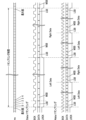
図4は、I2Sデータのタイミングチャートを示す図である。図4では、1サンプリングで2チャンネルのデータを転送する転送例と、1サンプリングで4チャンネルのデータを転送する、より高速な転送例を併記する。前者の転送例では、1サンプリング中に、Lチャンネルのデータ、Rチャンネルのデータが順に転送される。後者の転送例では、1サンプリング中に、Lチャンネルのデータ、Rチャンネルのデータ、Lチャンネルのデータ、Rチャンネルのデータが順に転送される。 Fig. 4 is a timing chart of I2S data. Fig. 4 shows a transfer example in which two-channel data is transferred in one sampling, and a faster transfer example in which four-channel data is transferred in one sampling. In the former transfer example, L channel data and R channel data are transferred in sequence during one sampling. In the latter transfer example, L channel data, R channel data, L channel data and R channel data are transferred in sequence during one sampling.
何れの転送例においても、BCK信号及びLRCK信号は、図4中、最上段に示された値mcをもとに生成される。 In either transfer example, the BCK and LRCK signals are generated based on the value mc shown in the top row of Figure 4.
なお、8、16、32チャンネルなど、1サンプリング中により多くのチャンネルのデータを転送する構成も本発明の範疇である。 Note that configurations that transfer data from more channels during one sampling, such as 8, 16, or 32 channels, are also within the scope of this invention.
また、デジタル楽音データの転送フォーマットは、I2Sフォーマットに限らず、例えば左寄せ(Left Justified)、右寄せ(Right Justified)等の別のフォーマットであってもよい。 Furthermore, the transfer format of the digital musical sound data is not limited to the I 2 S format, but may be another format such as left justified or right justified.
図5は、複数の音源コア15Cの各々に接続可能なスイッチマトリクス回路15SWの構成を示すブロック図である。図5に示されるように、スイッチマトリクス回路15SWは、6つのセレクタスイッチ150~155を含む。セレクタスイッチ150~155は、9 to 1のセレクタスイッチであり、且つ1ビットセレクタスイッチである。
Figure 5 is a block diagram showing the configuration of a switch matrix circuit 15SW that can be connected to each of the multiple
スイッチマトリクス回路15SWには、9系統の入力がある。具体的には、2つの音源コア15CのI2Sインタフェース108に備えられる3つの出力ポートからの入力(計6系統の入力:IN1~IN6)及び外部(例えばサウンドシステム3)からの計3系統の入力(IN7~IN9)がある。また、スイッチマトリクス回路15SWには、分配出力する系統として6系統ある。具体的には、2つの音源コア15CのI2Sインタフェース108に備えられる3つの入力ポートへの出力(計6系統の分配出力:OUT1~OUT6)がある。なお、スイッチマトリクス回路15SWにおいて、音源コア15Cからの入力は外部にスルー出力される。そのため、スイッチマトリクス回路15SWは、9 to 1のセレクタスイッチを6つ備える構成となっている。
The switch matrix circuit 15SW has nine inputs. Specifically, there are inputs from three output ports provided on the I 2 S interfaces 108 of the two
例えば、音源コア15CMにおいて音源コア15CSのLR信号(デジタル楽音データ)を加工するため、音源コア15CSのLR信号の2系統を音源コア15CMに入力させる場合を考える。この場合、例えば、セレクタスイッチ150において、ビット4、すなわちIN4を選択することでIN4とOUT1とが接続される。同様に、セレクタスイッチ151において、ビット5、すなわちIN5を選択することでIN5とOUT2とが接続される。これにより、音源コア15CSからIN4、IN5に入力されたL信号、R信号が、それぞれ、OUT1、OUT2から出力されて、音源コア15CMに入力される。
For example, consider the case where two systems of LR signals from sound source core 15CS are input to sound source core 15CM in order to process the LR signals (digital musical sound data) of sound source core 15CS in sound source core 15CM. In this case, for example, by selecting bit 4, i.e. IN4, in
別の例として、外部入力信号を音源コア15CSに入力させる場合を考える。この場合、例えば、セレクタスイッチ155において、ビット7、すなわちIN7を選択することでIN7とOUT6とが接続される。これにより、外部からIN7に入力された外部入力信号がOUT6から出力されて、音源コア15CSに入力される。
As another example, consider the case where an external input signal is input to the tone generator core 15CS. In this case, for example, by selecting bit 7, i.e. IN7, in the
このように、スイッチマトリクス回路15SWを構成することにより、スイッチマトリクス回路15SWの各種動作パターンを設定することができる。例えば、音源コア15CSから音源コア15CMへI2Sデータを転送する動作パターンを設定することができ、また、音源コア15CMから音源コア15CSへI2Sデータを転送する動作パターンを設定することができる。 By configuring the switch matrix circuit 15SW in this manner, various operation patterns of the switch matrix circuit 15SW can be set. For example, an operation pattern can be set in which I2S data is transferred from the tone generator core 15CS to the tone generator core 15CM, and an operation pattern can be set in which I2S data is transferred from the tone generator core 15CM to the tone generator core 15CS.
前者の動作パターンを採用する製品にスイッチマトリクス回路を搭載する場合も、後者の動作パターンを採用する製品にスイッチマトリクス回路を搭載する場合も、同じスイッチマトリクス回路15SWを利用することができる。異なる製品間で同じスイッチマトリクス回路15SWを利用できるため、例えばコストダウンが達成される。 The same switch matrix circuit 15SW can be used whether the switch matrix circuit is installed in a product that employs the former operating pattern or in a product that employs the latter operating pattern. Because the same switch matrix circuit 15SW can be used between different products, for example, cost reductions can be achieved.
例えば、BCK信号及びLRCK信号の位相が2つの音源コア15C間で揃わない状態で、I2Sデータを2つの音源コア15C間で受け渡す場合を考える。この場合、I2Sデータのうち、BCK信号、LRCK信号、DATA信号の全てに対してスイッチマトリクスを設ける必要がある。そのため、セレクタスイッチ150~155の個々を3ビットセレクタスイッチで構成する必要がある。
For example, consider a case where I2S data is transferred between two
これに対し、本実施形態では、上述したように、BCK信号及びLRCK信号の位相が2つの音源コア15C間で揃う。そのため、I2Sデータのうち、BCK信号及びLRCK信号に対してはスイッチマトリクスを設ける必要がない。DATA信号用として、セレクタスイッチ150~155の個々を1ビットセレクタスイッチで構成すればよいため、スイッチマトリクス回路15SWの回路規模が小さく抑えられる。言い換えると、スイッチマトリクス回路15SWにより接続を制御される信号にクロックの信号(BCK信号及びLRCK信号)を含まないため、スイッチマトリクス回路15SWの回路規模が小さく抑えられる。
In contrast, in this embodiment, as described above, the phases of the BCK signal and the LRCK signal are aligned between the two
図6は、DSP104によるエフェクト処理例を示す図である。図6では、音源コア15CMに備えられるミキサ102、DSP104を、それぞれ「ミキサ102M」、「DSP104M」と記し、音源コア15CSに備えられるミキサ102、DSP104を、それぞれ「ミキサ102S」、「DSP104S」と記す。
Figure 6 is a diagram showing an example of effect processing by
図6に示されるように、DSP104Mは、システムエフェクト処理部202、204、マスタエフェクト処理部206、208、インサーションエフェクト処理部210、212、加算器220、222及び224を備える。DSP104Sは、インサーションエフェクト処理部302、304、306、加算器320、322及び324を備える。
As shown in FIG. 6, the
システムエフェクト処理部202及び204は、各音源コア15Cで共有するシステムエフェクト(例えば、センドリターン端子に接続して、楽音全体に背景音的にかけることが一般的なリバーブ等のエフェクト)をかける。そのため、システムエフェクト処理部202及び204は、DSP104Mのミキサ102Mだけでなく、DSP104Sにも接続される。
The
ここで、インサーションエフェクト処理部210、212、302、304、306及びシステムエフェクト処理部204において、図6中左側(ミキサ102M又は102S側)への出力信号に対する増幅器は、システムエフェクト処理部202及び204に入力する信号のセンドボリュームとして機能している。
Here, in the
一方、システムエフェクト処理部202、204において、図6中右側への出力信号に対する増幅器は、それぞれ、システムエフェクト処理部202、204からの戻り信号のリターンボリュームとして機能している。但し、本実施形態におけるシステムエフェクト処理部204であるコーラスは、インサーションエフェクトとしても機能し得る。システムエフェクト処理部204のコーラスをインサーションエフェクトとして機能させる場合は、同処理部のシステムエフェクト処理部202へのセンドボリュームを0とし、各インサーションエフェクト処理部210、212、302、304、306のシステムエフェクト処理部204へのセンドボリュームを0とすればよい。
Meanwhile, in the
システムエフェクト処理部202の前段に配置された加算器220は、ミキサ102M、システムエフェクト処理部204、インサーションエフェクト処理部210及び212から出力されるデジタル楽音データ(リバーブ処理のための波形データ)を加算し、更に、DSP104Sから出力されるデジタル楽音データ(より詳細には、インサーションエフェクト処理部302、304、306から出力されて加算器320で加算された、リバーブ処理のための波形データ)を加算する。システムエフェクト処理部202は、加算器220より入力される波形データを用いてリバーブ楽音を生成し、生成されたリバーブ楽音の波形データを出力する。
The
システムエフェクト処理部204の前段に配置された加算器222は、ミキサ102M、インサーションエフェクト処理部210及び212から出力されるデジタル楽音データ(コーラス処理のための波形データ)を加算し、更に、DSP104Sから出力されるデジタル楽音データ(より詳細には、インサーションエフェクト処理部302、304、306から出力されて加算器322で加算された、コーラス処理のための波形データ)を加算する。システムエフェクト処理部202は、加算器222より入力される波形データを用いてコーラス楽音を生成し、生成されたコーラス楽音の波形データを出力する。
The
マスタエフェクト処理部206及び208は、各システムエフェクト処理部及び各インサーションエフェクト処理部の後段で、各音源コア15Cで共有するマスタエフェクトをかける。そのため、マスタエフェクト処理部206及び208は、各システムエフェクト処理部及び各インサーションエフェクト処理部並びにミキサ102Mに接続される。
The
マスタエフェクト処理部206の前段に配置された加算器224は、ミキサ102M、システムエフェクト処理部202、204、インサーションエフェクト処理部210、212から出力される波形データを加算し、更に、DSP104Sから出力される波形データ(より詳細には、ミキサ102S、インサーションエフェクト処理部302、304、306から出力されて加算器324で加算された波形データ)を加算する。
The
マスタエフェクト処理部206は、加算器224で加算されることによって得られるデジタル楽音データに対して、コンプレッサ処理を施す。マスタエフェクト処理部208は、マスタエフェクト処理部206によるコンプレッサ処理後のデジタル楽音データに対して、イコライザ処理を施す。イコライザ処理後のデジタル楽音データは、I2Sインタフェース108を介してサウンドシステム3に出力される。
The
マスタエフェクト処理部206及び208は、楽音の最終出力段において音量差を調整したり周波数特性を調整したりして、楽音全体を整える役割を担う。そのため、システムエフェクトを通らない直接音については、レイテンシを最小限に抑えて、複数の音源コア15C間で位相がなるべく揃った状態の信号が加算器224で加算されてマスタエフェクト処理部206に入力されることが望ましい。
The
インサーションエフェクト処理部210及び212は、ミキサ102Mより入力されるデジタル楽音データに対してだけインサーションエフェクトをかける。すなわち、インサーションエフェクト処理部210及び212は、各音源コア15Cで共有しないエフェクトをかける。例えば、インサーションエフェクト処理部210とインサーションエフェクト処理部212は、互いに異なるインサーションエフェクト(一例としてフランジャとフェイザ等)をかける。
The
インサーションエフェクト処理部302、304及び306は、ミキサ102Sより入力されるデジタル楽音データに対してだけインサーションエフェクトをかける。すなわち、インサーションエフェクト処理部302、304及び306も、各音源コア15Cで共有しないエフェクトをかける。
The
インサーションエフェクト処理部210、212、302、304、306の出力信号は図6中左側(ミキサ102M又は102S側)に向い、システムエフェクトを通る信号と、図6中右側に向い、システムエフェクトを通らない直接音の信号とに分かれる。直接音は、リバーブやコーラスなどのシステムエフェクトを通る背景音に比較して、レイテンシが少ないことが望ましい。
The output signals of the insertion
本実施形態において、音源コア15CSで発生されたデジタル楽音データは、スイッチマトリクス回路15SW経由又は共有メモリ経由で、音源コア15CMへ転送される。ここで、図7Aに、デジタル楽音データをスイッチマトリクス回路15SW経由で転送する場合のレイテンシを示す。また、図7Bに、デジタル楽音データを共有メモリ経由で転送する場合のレイテンシを示す。 In this embodiment, the digital musical sound data generated by the tone generator core 15CS is transferred to the tone generator core 15CM via the switch matrix circuit 15SW or via the shared memory. Figure 7A shows the latency when the digital musical sound data is transferred via the switch matrix circuit 15SW. Figure 7B shows the latency when the digital musical sound data is transferred via the shared memory.
本実施形態では、シングルアクセスのレイテンシの小さいRAM11(SRAM)が共有メモリとして用いられる。 In this embodiment, a RAM 11 (SRAM) with low single-access latency is used as the shared memory.
図7Aに示されるように、スイッチマトリクス回路15SW経由の場合、DSP104Sのレジスタに対してI2Sデータが書き込まれ、書き込まれたI2Sデータが転送され、転送されたI2SデータがDSP104Mのレジスタに書き込まれる。そのため、音源コア15CSで発生されたデジタル楽音データは、音源コア15CMで発生されたデジタル楽音データに対して2サンプリング程度遅延する。
7A, in the case of passing through the switch matrix circuit 15SW, the I2S data is written to a register of the
図7Bに示されるように、共有メモリ経由の場合、共有メモリ領域が確保され、確保された共有メモリ領域にデジタル楽音データが書き込まれ、書き込まれたデジタル楽音データが共有メモリ領域から読み出され、読み出されたデジタル楽音データがDSP104Mのキャッシュメモリに書き込まれる。そのため、音源コア15CSで発生されたデジタル楽音データは、音源コア15CMで発生されたデジタル楽音データに対して3サンプリング程度遅延する。
As shown in FIG. 7B, when passing through a shared memory, a shared memory area is secured, the digital musical sound data is written into the secured shared memory area, the written digital musical sound data is read from the shared memory area, and the read digital musical sound data is written into the cache memory of
なお、RAM11の動作状況によっては、共有メモリにおけるライトレイテンシ、リードレイテンシがより大きくなる可能性が十分にある。そのため、音源コア15CSで発生されたデジタル楽音データは、音源コア15CMで発生されたデジタル楽音データに対してより大きく遅延することもある。
Depending on the operating conditions of
すなわち、デジタル楽音データをスイッチマトリクス回路15SW経由で転送する場合、共有メモリ経由で転送する場合と比べてレイテンシが小さく抑えられる。 In other words, when digital musical sound data is transferred via the switch matrix circuit 15SW, the latency is kept small compared to when it is transferred via shared memory.
前述したように、各インサーションエフェクトからの直接音は、システムエフェクトを通る音に比較して低レイテンシであることが望ましい。そのため、音源コア15CSからマスタエフェクト処理部206には、CPU10による制御のもと、レイテンシの小さい経路で(すなわちスイッチマトリクス回路15SW経由で)、ミキサ102S並びにDSP104Sのインサーションエフェクト処理部302、304及び306より出力されるデジタル楽音データ(すなわち加算器324による加算後の波形データ)が転送される。
As mentioned above, it is desirable for the direct sound from each insertion effect to have low latency compared to the sound that passes through the system effect. Therefore, under the control of the
但し、スイッチマトリクス回路15SW経由では、入出力の経路数に制限がある。入出力経路を増やす場合にはスイッチマトリクス回路15SWの入出力数を増やすこととなり、スイッチマトリクス回路15SWの回路規模が大きくなってしまう。 However, there is a limit to the number of input/output paths via the switch matrix circuit 15SW. Increasing the number of input/output paths requires increasing the number of inputs/outputs of the switch matrix circuit 15SW, which increases the circuit size of the switch matrix circuit 15SW.
これに対し、共有メモリ経由では、RAM11上にリングバッファを形成すれば、転送できる経路数はほぼ無制限となる。また、リングバッファのサイズを増やすことにより、1経路あたりの転送データ量を増やすこともできる。但し、この場合は、書き込んだデータが読み込まれるまでのレイテンシが大きくなる。また、システムエフェクト処理部202及び204によるリバーブ処理及びコーラス処理は、上述したように、インサーションエフェクト処理と比較して、多少レイテンシが大きくてもよい。
In contrast, when using shared memory, if a ring buffer is formed in
そこで、本実施形態では、音源コア15CSからシステムエフェクト処理部202には、CPU10による制御のもと、共有メモリ経由で、DSP104Sのインサーションエフェクト処理部302、304及び306より出力されるデジタル楽音データ(すなわち加算器320による加算後の波形データ)が転送される。また、音源コア15CSからシステムエフェクト処理部204には、CPU10による制御のもと、共有メモリ経由で、DSP104Sのインサーションエフェクト処理部302、304及び306より出力されるデジタル楽音データ(すなわち加算器322による加算後の波形データ)が転送される。
In this embodiment, digital musical tone data (i.e., waveform data after addition by adder 320) output from insertion
このように、本実施形態では、スイッチマトリクス回路15SWと共有メモリとを併用することにより、スイッチマトリクス回路15SWの回路規模を小さく抑えつつ、1サンプリング中に多くのデータを転送できるようになっている。 In this way, in this embodiment, by using the switch matrix circuit 15SW in combination with a shared memory, it is possible to transfer a large amount of data during one sampling while keeping the circuit scale of the switch matrix circuit 15SW small.
なお、図6に示される処理例はあくまで一例に過ぎない。リバーブ、コーラス、コンプレッサ及びイコライザを共有しない構成や、本実施形態では非共有なインサーションエフェクトを共有する構成も、本発明の範疇である。また、図6に例示されない別のエフェクト処理を行う構成も、本発明の範疇である。 The processing example shown in FIG. 6 is merely one example. Configurations that do not share reverb, chorus, compressor, and equalizer, and configurations that share insertion effects that are not shared in this embodiment, are also within the scope of the present invention. Additionally, configurations that perform other effect processing not exemplified in FIG. 6 are also within the scope of the present invention.
このように、CPU10は、ROM12に格納されたプログラムを実行することにより、クロック(BCK信号及びLRCK信号)の位相が揃えられたデジタル楽音データが複数の音源コア15C間で転送されるように、複数の音源コア15C間の接続を制御する、接続制御部として動作する。より詳細には、接続制御部として動作するCPU10は、スイッチマトリクス回路15SWを介した、複数の音源コア15C間の接続を制御する。
In this way, the
また、複数の音源コア15Cのうちの1つの音源コア15CMは、複数の音源コア15Cの各々からの第1の楽音データ、第2の楽音データのそれぞれに対して、第1のエフェクト処理、第2のエフェクト処理を施す。第1の楽音データは、転送時のレイテンシに対する許容値が第2のエフェクト処理(例えばリバーブ処理、コーラス処理)よりも小さい第1のエフェクト処理(例えばインサーションエフェクト処理)が施されるデジタル楽音データであり、複数の音源コア15C間においてI2Sフォーマットで転送される。第2の楽音データは、転送時のレイテンシに対する許容値が第1のエフェクト処理よりも大きい第2のエフェクト処理が施されるデジタル楽音データであり、複数の音源コア15C間において共有メモリを介して転送される。附言するに、第1のエフェクト処理は、第2のエフェクト処理と比べて、楽音データの転送時のレイテンシが小さいことが要求される処理といえる。
Moreover, one tone generator core 15CM among the plurality of
以上のように、本実施形態では、BCK信号及びLRCK信号の位相が複数の音源コア15C間で揃うため、複数の音源コア15C間でエフェクトを共有させる構成でありながらも、セレクタスイッチ150~155の個々を1ビットセレクタスイッチで構成することができ、スイッチマトリクス回路15SWの回路規模が小さく抑えられる。
As described above, in this embodiment, the phases of the BCK signal and the LRCK signal are aligned between multiple
その他、本発明は上述した実施形態に限定されるものではなく、実施段階ではその要旨を逸脱しない範囲で種々に変形することが可能である。また、上述した実施形態で実行される機能は可能な限り適宜組み合わせて実施しても良い。上述した実施形態には種々の段階が含まれており、開示される複数の構成要件による適宜の組み合せにより種々の発明が抽出され得る。例えば、実施形態に示される全構成要件からいくつかの構成要件が削除されても、効果が得られるのであれば、この構成要件が削除された構成が発明として抽出され得る。 In addition, the present invention is not limited to the above-described embodiment, and various modifications can be made in the implementation stage without departing from the gist of the invention. Furthermore, the functions performed in the above-described embodiment may be implemented in appropriate combinations as much as possible. The above-described embodiment includes various steps, and various inventions can be extracted by appropriate combinations of the multiple components disclosed. For example, if the effect can be obtained even if some components are deleted from all the components shown in the embodiment, then the configuration from which these components are deleted can be extracted as an invention.
図8は、本発明の変形例1におけるDSP104によるエフェクト処理例を示す図である。
Figure 8 shows an example of effect processing by the
上述したように、音源コア15CSで発生されたデジタル楽音データは、転送時のレイテンシがあるため、音源コア15CMで発生されたデジタル楽音データに対して遅延する。そこで、変形例1では、システムエフェクト処理部202、204、インサーションエフェクト処理部210及び212の後段に、ディレイ回路230が配置される。ディレイ回路230は、入力される波形データを例えば2サンプリング遅延させる。
As mentioned above, the digital musical sound data generated by the tone generator core 15CS is delayed relative to the digital musical sound data generated by the tone generator core 15CM due to the latency during transfer. Therefore, in the first modification, a
ディレイ回路230で遅延された波形データとミキサ102Mからの波形データとが加算器226で加算され、更に、この加算データが、加算器224で、音源コア15CSからスイッチマトリクス回路15SW経由で転送された波形データと加算されて、マスタエフェクト処理部206に入力される。
The waveform data delayed by the
すなわち、変形例1では、音源コア15CSで発生されたデジタル楽音データ(スイッチマトリクス回路15SWを経由した波形データ)と、音源コア15CMで発生されたデジタル楽音データ(スイッチマトリクス回路15SWを経由しない波形データ)との位相差が抑えられたデジタル楽音データがマスタエフェクト処理部206に入力される。
In other words, in
このように、音源コア15CMは、複数の音源コア15Cの各々からの楽音データの位相差を抑えるディレイ回路230(位相差抑制部の一例)を含む。
Thus, the tone generator core 15CM includes a delay circuit 230 (an example of a phase difference suppression unit) that suppresses the phase difference of the musical sound data from each of the multiple
複数の音源コア15C間の動作カウンタ112の同期制御を行う方法は、リセットパルスを用いた方法に限らない。
The method of controlling synchronization of the operation counters 112 between multiple
図9A、図9Bは、それぞれ、音源コア15CM、音源コア15CSに対応する図であり、本発明の変形例2に係るスイッチ110’及び動作カウンタ112の構成を示すブロック図である。変形例2に係る音源システム1は、図3に示される構成に代えて、図9A及び図9Bに示される構成を備える。
Figures 9A and 9B correspond to tone generator core 15CM and tone generator core 15CS, respectively, and are block diagrams showing the configuration of switch 110' and
CPU10は、マスタとして設定された音源コア15CMに対して値1のマスタイネーブル信号を出力するとともに、スレーブとして設定された音源コア15CSに対して値0のマスタイネーブル信号を出力する。マスタイネーブル信号は、スイッチ110’に対する制御信号である。
The
図9Aに示されるように、音源コア15CMにおいて、スイッチ110’は、マスタイネーブル信号に従い、接点T11と接続する。これにより、音源コア15CMの動作カウンタ112と音源コア15CM内部(値mcの供給先)とが接続されるとともに、音源コア15CSの動作カウンタ112と音源コア15CM内部との接続が遮断される。
As shown in FIG. 9A, in the tone generator core 15CM, the switch 110' connects to the contact T11 in response to the master enable signal. This connects the
また、図9Bに示されるように、音源コア15CSにおいて、スイッチ110’は、マスタイネーブル信号に従い、接点T12と接続する。これにより、音源コア15CSの動作カウンタ112と音源コア15CS内部(値mcの供給先)との接続が遮断されるとともに、音源コア15CMの動作カウンタ112と音源コア15CS内部とが接続される。
Also, as shown in FIG. 9B, in the tone generator core 15CS, the switch 110' connects to the contact T12 in response to the master enable signal. This disconnects the
従って、音源コア15CMの動作カウンタ112で発生された値mcは、音源コア15CM内部へ供給されるとともに、音源コア15CS内部へ供給される。2つの音源コア15Cに対して共通の値mcが供給されるため、値mcをもとに生成されるBCK信号及びLRCK信号の位相が2つの音源コア15C間で揃う。
The value mc generated by the
楽音の発音状態によっては(例えば発音対象の楽音が少ない場合)、少なくとも一方の音源コア15Cを動作させる必要がなくなる。そこで、音源システム1の消費電流を減らすため、楽音の発音状態に応じて(言い換えると、楽音データの処理状況に応じて)少なくとも一方の音源コア15Cへの基本動作クロックの供給を停止してもよい。
Depending on the tone generation state (for example, when there are few tones to be generated), it may not be necessary to operate at least one of the
図10は、本発明の変形例3に係る音源システム1の構成を示すブロック図である。図10では、音源システム1の各部に対して基本動作クロックを供給するクロックジェネレータ17を示す。クロックジェネレータ17は、複数の音源コア15Cを動作させる基本動作クロックを供給する基本動作クロック供給部の一例である。
Figure 10 is a block diagram showing the configuration of a
図10に示されるように、変形例3では、クロックジェネレータ17と音源コア15CMとの間に、クロックゲーティングスイッチ18Mが配置される。また、クロックジェネレータ17と音源コア15CSとの間に、クロックゲーティングスイッチ18Sが配置される。
As shown in FIG. 10, in the third modification, a
CPU10は、楽音の発音状態に応じて設定レジスタ19に値を書き込む。例えば、音源コア15CMについて値1が書き込まれると、設定レジスタ19からクロックゲーティングスイッチ18Mへ値1のイネーブル信号が出力される。これにより、クロックゲーティングスイッチ18Mがクロックジェネレータ17と音源コア15CMとを接続し、クロックジェネレータ17から音源コア15CMへ基本動作クロックが供給される。音源コア15CMについて値0が書き込まれると、設定レジスタ19からクロックゲーティングスイッチ18Mへ値0のイネーブル信号が出力される。これにより、クロックゲーティングスイッチ18Mがクロックジェネレータ17と音源コア15CMとの接続を遮断し、クロックジェネレータ17から音源コア15CMへの基本動作クロックの供給が停止される。そのため、音源コア15CMが停止する。
The
音源コア15CSについても同様の動作で、クロックゲーティングスイッチ18Sによる、クロックジェネレータ17と音源コア15CSとの接続及び接続の遮断が行われる。クロックジェネレータ17と音源コア15CSとの接続中、クロックジェネレータ17から音源コア15CSへ基本動作クロックが供給される。クロックジェネレータ17と音源コア15CSとの接続の遮断中、クロックジェネレータ17から音源コア15CSへの基本動作クロックの供給が停止されるため、音源コア15CSが停止する。
A similar operation is performed for the tone generator core 15CS, where the
このように、CPU10は、ROM12に格納されたプログラムを実行することにより、デジタル楽音データの処理状況に応じて、クロックジェネレータ17(基本動作クロック供給部の一例)による、複数の音源コア15Cの各々への基本動作クロックの供給及び供給の停止を制御する、供給制御部として動作する。
In this way, the
図9に示される構成では、音源コア15CMが音源コア15CSに値mcを供給する。音源コア15CMだけ停止させると、音源コア15CSに値mcが供給されないため、音源コア15CSの動作に不具合が生じる。そこで、停止可能な音源コア15Cが1つだけの場合、音源コア15CSだけが停止される。停止可能な音源コア15Cが2つになったときにはじめて、音源コア15CMも停止される。
In the configuration shown in FIG. 9, sound source core 15CM supplies the value mc to sound source core 15CS. If only sound source core 15CM is stopped, the value mc will not be supplied to sound source core 15CS, causing a malfunction in the operation of sound source core 15CS. Therefore, if there is only one
図9に示される構成では、2つの音源コア15Cが停止されている状態から音源コア15CSの動作だけ再開させても、値mcが音源コア15CSに供給されない。そのため、音源コア15CSの動作に不具合が生じる。そこで、まずは、音源コア15CMの動作だけ再開し、次いで、必要に応じて音源コア15CSの動作も再開する。
In the configuration shown in FIG. 9, even if the operation of only the sound source core 15CS is resumed from a state in which the two
図9に示される構成では、音源コア15CSの動作が再開されると、音源コア15CMの動作カウンタ112で発生された値mcが音源コア15CS内部にも供給される。そのため、BCK信号及びLRCK信号の位相が動作再開後も2つの音源コア15C間で揃う。
In the configuration shown in FIG. 9, when the operation of the tone generator core 15CS is resumed, the value mc generated by the
図3に示される構成では、音源コア15CSの動作再開時に、各音源コア15Cにリセットパルスが供給される。そのため、この場合も、BCK信号及びLRCK信号の位相が動作再開後も2つの音源コア15C間で揃う。
In the configuration shown in FIG. 3, when the tone generator core 15CS resumes operation, a reset pulse is supplied to each
以下、本願の出願当初の特許請求の範囲に記載された発明を付記する。
[付記1]
楽音データを処理する複数の音源コアと、
前記音源コアに対する前記楽音データの入出力タイミングを規定するクロックの位相を、前記複数の音源コア間で揃える位相制御部と、
前記クロックの位相が揃えられた楽音データが前記複数の音源コア間で転送されるように、前記複数の音源コア間の接続を制御する、接続制御部と、を備える、
音源システム。
[付記2]
前記複数の音源コアの各々に接続可能なスイッチマトリクス回路を更に備え、
前記接続制御部は、前記スイッチマトリクス回路を介した、前記複数の音源コア間の接続を制御する
付記1に記載の音源システム。
[付記3]
前記スイッチマトリクス回路により接続を制御される信号に、前記クロックの信号を含まない、
付記2に記載の音源システム。
[付記4]
前記複数の音源コア間において、第1の前記楽音データは、I2S(Inter-IC Sound Interface)フォーマットで転送される、
付記1から付記3の何れか一項に記載の音源システム。
[付記5]
前記複数の音源コア間で共有する共有メモリを更に備え、
前記複数の音源コア間において、第2の前記楽音データは、前記共有メモリを介して転送される、
付記4に記載の音源システム。
[付記6]
前記複数の音源コアのうちの1つの音源コアは、前記複数の音源コアの各々からの前記第1の楽音データ、前記第2の楽音データのそれぞれに対して、第1のエフェクト処理、第2のエフェクト処理を施し、
前記第1のエフェクト処理は、前記第2のエフェクト処理と比べて、前記楽音データの転送時のレイテンシが小さいことが要求される処理である、
付記5に記載の音源システム。
[付記7]
前記1つの音源コアは、前記複数の音源コアの各々からの前記楽音データの位相差を抑える位相差抑制部を含む、
付記6に記載の音源システム。
[付記8]
前記位相制御部は、前記複数の音源コアの各々にトリガ信号を供給し、
前記複数の音源コアの各々に前記トリガ信号が供給されると、前記複数の音源コア間で前記音源コアの動作カウンタの値が同期し、
前記複数の音源コアの各々は、同期した状態の前記動作カウンタの値に基づいて前記クロックを生成する、
付記1から付記7の何れか一項に記載の音源システム。
[付記9]
前記複数の音源コアを動作させる基本動作クロックを供給する基本動作クロック供給部と、
前記楽音データの処理状況に応じて、前記基本動作クロック供給部による、前記複数の音源コアの各々への前記基本動作クロックの供給及び供給の停止を制御する、供給制御部と、を更に備える、
付記1から付記8の何れか一項に記載の音源システム。
[付記10]
前記複数の音源コアは、同一構造である、
付記1から付記9の何れか一項に記載の音源システム。
[付記11]
楽音データを処理する複数の音源コアを備える音源システムを制御する方法であり、
前記音源コアに対する前記楽音データの入出力タイミングを規定するクロックの位相を、前記複数の音源コア間で揃え、
前記クロックの位相が揃えられた楽音データが前記複数の音源コア間で転送されるように、前記複数の音源コア間の接続を制御する、処理を、前記音源システムに実行させる、
方法。
[付記12]
楽音データを処理する複数の音源コアを備える音源システムを制御するプログラムであり、
前記音源コアに対する前記楽音データの入出力タイミングを規定するクロックの位相を、前記複数の音源コア間で揃え、
前記クロックの位相が揃えられた楽音データが前記複数の音源コア間で転送されるように、前記複数の音源コア間の接続を制御する、処理を、前記音源システムに実行させる、
プログラム。
The invention as described in the claims of the original application is set forth below.
[Appendix 1]
A plurality of sound source cores for processing musical sound data;
a phase control unit that aligns the phases of a clock that defines the input/output timing of the musical sound data to the tone generator cores among the plurality of tone generator cores;
a connection control unit that controls connections between the plurality of tone generator cores so that the tone data with the clock phases aligned is transferred between the plurality of tone generator cores;
Sound source system.
[Appendix 2]
a switch matrix circuit connectable to each of the plurality of sound source cores;
2. The tone generator system according to
[Appendix 3]
The signals whose connection is controlled by the switch matrix circuit do not include the clock signal.
3. The sound source system according to
[Appendix 4]
The first musical sound data is transferred between the plurality of sound source cores in an I2S (Inter-IC Sound Interface) format.
4. A sound source system according to any one of
[Appendix 5]
A shared memory shared among the plurality of tone generator cores is further provided,
the second musical sound data is transferred between the plurality of tone generator cores via the shared memory;
5. The sound source system according to claim 4.
[Appendix 6]
one of the plurality of tone generator cores performs a first effect process and a second effect process on the first musical sound data and the second musical sound data from each of the plurality of tone generator cores,
the first effect processing is processing that requires a smaller latency in transferring the musical sound data than the second effect processing;
6. The sound source system according to claim 5.
[Appendix 7]
the one tone generator core includes a phase difference suppression unit that suppresses a phase difference of the musical sound data from each of the plurality of tone generator cores;
7. The sound source system according to claim 6.
[Appendix 8]
The phase control unit supplies a trigger signal to each of the plurality of sound source cores;
when the trigger signal is supplied to each of the plurality of tone generator cores, values of operation counters of the tone generator cores are synchronized among the plurality of tone generator cores;
Each of the plurality of tone generator cores generates the clock based on a value of the operation counter in a synchronized state.
8. A sound source system according to any one of
[Appendix 9]
a basic operation clock supply unit that supplies a basic operation clock for operating the plurality of tone generator cores;
a supply control unit that controls the supply and stop of the basic operation clock to each of the plurality of tone generator cores by the basic operation clock supply unit according to a processing status of the musical sound data.
9. A sound source system according to any one of
[Appendix 10]
The multiple sound source cores have the same structure.
10. The sound source system according to any one of
[Appendix 11]
A method for controlling a sound source system having a plurality of sound source cores for processing musical sound data,
aligning the phases of clocks that define the input/output timing of the musical sound data to/from the tone generator cores among the plurality of tone generator cores;
causing the tone generator system to execute a process of controlling connections between the plurality of tone generator cores so that the musical sound data with the clock phases aligned is transferred between the plurality of tone generator cores;
method.
[Appendix 12]
A program for controlling a sound source system having a plurality of sound source cores for processing musical sound data,
aligning the phases of clocks that define the input/output timing of the musical sound data to/from the tone generator cores among the plurality of tone generator cores;
causing the tone generator system to execute a process of controlling connections between the plurality of tone generator cores so that the musical sound data with the clock phases aligned is transferred between the plurality of tone generator cores;
program.
1 :音源システム
2 :DRAM
3 :サウンドシステム
10 :CPU
11 :RAM
12 :ROM
13 :GPIO
14 :MEMIF
15 :コア部
15C :音源コア
15SW :スイッチマトリクス回路
16 :バス
100 :音源部
102 :ミキサ
104 :DSP
106 :BIF
108 :I2Sインタフェース
110 :リセットパルス入出力回路
112 :動作カウンタ
150~155:セレクタスイッチ
1: Sound source system 2: DRAM
3: Sound system 10: CPU
11: RAM
12: ROM
13: GPIO
14: MEMIF
15:
106: BIF
108: I 2 S interface 110: Reset pulse input/output circuit 112:
Claims (15)
前記音源コアに対する前記楽音データの入出力タイミングを規定するクロックの位相を、前記複数の音源コア間で揃える位相制御部と、
前記クロックの位相が揃えられた楽音データが前記複数の音源コア間で転送されるように、前記複数の音源コア間の接続を制御する、接続制御部と、
前記複数の音源コア間で共有する共有メモリと、を備え、
前記複数の音源コアのうちの1つの音源コアは、前記共有メモリを介さずに転送される第1の楽音データ、前記共有メモリを介して転送される第2の楽音データのそれぞれに対して、第1のエフェクト処理、第2のエフェクト処理を施し、
前記第1のエフェクト処理は、前記第2のエフェクト処理と比べて、前記楽音データの転送時のレイテンシが小さいことが要求される処理である、
音源システム。 A plurality of sound source cores for processing musical sound data;
a phase control unit that aligns the phases of a clock that defines the input/output timing of the musical sound data to the tone generator cores among the plurality of tone generator cores;
a connection control unit that controls connections between the plurality of tone generator cores so that the tone data with the clock phases aligned is transferred between the plurality of tone generator cores;
a shared memory shared among the plurality of tone generator cores;
one of the plurality of tone generator cores performs a first effect process and a second effect process on the first musical sound data transferred without passing through the shared memory and the second musical sound data transferred through the shared memory, respectively;
the first effect processing is processing that requires a smaller latency in transferring the musical sound data than the second effect processing;
Sound source system.
前記音源コアに対する前記楽音データの入出力タイミングを規定するクロックの位相を、前記複数の音源コア間で揃える位相制御部と、
前記クロックの位相が揃えられた楽音データが前記複数の音源コア間で転送されるように、前記複数の音源コア間の接続を制御する、接続制御部と、を備え、
前記位相制御部は、前記複数の音源コアの各々にトリガ信号を供給し、
前記複数の音源コアの各々に前記トリガ信号が供給されると、前記複数の音源コア間で前記音源コアの動作カウンタの値が同期し、
前記複数の音源コアの各々は、同期した状態の前記動作カウンタの値に基づいて前記クロックを生成する、
音源システム。 A plurality of sound source cores for processing musical sound data;
a phase control unit that aligns the phases of a clock that defines the input/output timing of the musical sound data to the tone generator cores among the plurality of tone generator cores;
a connection control unit that controls connections between the plurality of tone generator cores so that the tone data with the clock phases aligned is transferred between the plurality of tone generator cores;
The phase control unit supplies a trigger signal to each of the plurality of sound source cores;
when the trigger signal is supplied to each of the plurality of tone generator cores, values of operation counters of the tone generator cores are synchronized among the plurality of tone generator cores;
Each of the plurality of tone generator cores generates the clock based on a value of the operation counter in a synchronized state.
Sound source system.
前記音源コアに対する前記楽音データの入出力タイミングを規定するクロックの位相を、前記複数の音源コア間で揃える位相制御部と、
前記クロックの位相が揃えられた楽音データが前記複数の音源コア間で転送されるように、前記複数の音源コア間の接続を制御する、接続制御部と、
前記複数の音源コアを動作させる基本動作クロックを供給する基本動作クロック供給部と、
前記楽音データの処理状況に応じて、前記基本動作クロック供給部による、前記複数の音源コアの各々への前記基本動作クロックの供給及び供給の停止を制御する、供給制御部と、を備える、
音源システム。 A plurality of sound source cores for processing musical sound data;
a phase control unit that aligns the phases of a clock that defines the input/output timing of the musical sound data to the tone generator cores among the plurality of tone generator cores;
a connection control unit that controls connections between the plurality of tone generator cores so that the tone data with the clock phases aligned is transferred between the plurality of tone generator cores;
a basic operation clock supply unit that supplies a basic operation clock for operating the plurality of tone generator cores;
a supply control unit that controls the supply and stop of the basic operation clock to each of the plurality of tone generator cores by the basic operation clock supply unit according to a processing status of the musical sound data.
Sound source system.
前記接続制御部は、前記スイッチマトリクス回路を介した、前記複数の音源コア間の接続を制御する請求項1から請求項3の何れか一項に記載の音源システム。 a switch matrix circuit connectable to each of the plurality of sound source cores;
4. The tone generator system according to claim 1, wherein the connection control unit controls connections between the plurality of tone generator cores via the switch matrix circuit.
前記複数の音源コア間において、前記楽音データのうちの第2の楽音データは、前記共有メモリを介して転送される、請求項2又は3に記載の音源システム。 A shared memory shared among the plurality of tone generator cores is further provided,
4. The tone generator system according to claim 2, wherein the second tone data of the tone data is transferred between the plurality of tone generator cores via the shared memory.
前記複数の音源コアのうちの1つの音源コアは、前記複数の音源コアの各々からの前記第1の楽音データ、前記第2の楽音データのそれぞれに対して、第1のエフェクト処理、第2のエフェクト処理を施し、
前記第1のエフェクト処理は、前記第2のエフェクト処理と比べて、前記楽音データの転送時のレイテンシが小さいことが要求される処理である、請求項8に記載の音源システム。 the first musical sound data among the musical sound data is transferred in an I2S (Inter-IC Sound Interface) format between the plurality of tone generator cores;
one of the plurality of tone generator cores performs a first effect process and a second effect process on the first musical sound data and the second musical sound data from each of the plurality of tone generator cores,
9. The tone generator system according to claim 8, wherein the first effect processing is a processing that requires a smaller latency in the transfer of the tone data than the second effect processing.
前記複数の音源コアの各々に前記トリガ信号が供給されると、前記複数の音源コア間で前記音源コアの動作カウンタの値が同期し、
前記複数の音源コアの各々は、同期した状態の前記動作カウンタの値に基づいて前記クロックを生成する、請求項1又は3に記載の音源システム。 The phase control unit supplies a trigger signal to each of the plurality of sound source cores;
when the trigger signal is supplied to each of the plurality of tone generator cores, values of operation counters of the tone generator cores are synchronized among the plurality of tone generator cores;
The sound source system according to claim 1 or 3, wherein each of the plurality of sound source cores generates the clock based on a value of the operation counter in a synchronized state.
前記楽音データの処理状況に応じて、前記基本動作クロック供給部による、前記複数の音源コアの各々への前記基本動作クロックの供給及び供給の停止を制御する、供給制御部と、を更に備える、請求項1又は2に記載の音源システム。 a basic operation clock supply unit that supplies a basic operation clock for operating the plurality of tone generator cores;
3. The sound source system according to claim 1, further comprising a supply control unit that controls the supply and stop of the basic operation clock to each of the plurality of sound source cores by the basic operation clock supply unit depending on the processing status of the musical sound data.
前記音源コアに対する前記楽音データの入出力タイミングを規定するクロックの位相を、前記複数の音源コア間で揃え、
前記クロックの位相が揃えられた楽音データが前記複数の音源コア間で転送されるように、前記複数の音源コアの各々にトリガ信号を供給し、
前記複数の音源コアの各々に前記トリガ信号が供給されると、前記複数の音源コア間で前記音源コアの動作カウンタの値が同期し、
前記複数の音源コアの各々は、同期した状態の前記動作カウンタの値に基づいて前記クロックを生成する、処理を、前記音源システムに実行させる、
方法。 A method for controlling a sound source system having a plurality of sound source cores for processing musical sound data,
aligning the phases of clocks that define the input/output timing of the musical sound data to/from the tone generator cores among the plurality of tone generator cores;
supplying a trigger signal to each of the plurality of tone generator cores so that the tone data with the clock phases aligned is transferred between the plurality of tone generator cores;
when the trigger signal is supplied to each of the plurality of tone generator cores, values of operation counters of the tone generator cores are synchronized among the plurality of tone generator cores;
Each of the plurality of tone generator cores generates the clock based on the value of the operation counter in a synchronized state.
method.
前記音源コアに対する前記楽音データの入出力タイミングを規定するクロックの位相を、前記複数の音源コア間で揃え、
前記クロックの位相が揃えられた楽音データが前記複数の音源コア間で転送されるように、前記複数の音源コアの各々にトリガ信号を供給し、
前記複数の音源コアの各々に前記トリガ信号が供給されると、前記複数の音源コア間で前記音源コアの動作カウンタの値が同期し、
前記複数の音源コアの各々は、同期した状態の前記動作カウンタの値に基づいて前記クロックを生成する、処理を、前記音源システムに実行させる、
プログラム。 A program for controlling a sound source system having a plurality of sound source cores for processing musical sound data,
aligning the phases of clocks that define the input/output timing of the musical sound data to/from the tone generator cores among the plurality of tone generator cores;
supplying a trigger signal to each of the plurality of tone generator cores so that the tone data with the clock phases aligned is transferred between the plurality of tone generator cores;
when the trigger signal is supplied to each of the plurality of tone generator cores, values of operation counters of the tone generator cores are synchronized among the plurality of tone generator cores;
Each of the plurality of tone generator cores generates the clock based on the value of the operation counter in a synchronized state.
program.
Priority Applications (5)
| Application Number | Priority Date | Filing Date | Title |
|---|---|---|---|
| JP2022046539A JP7578112B2 (en) | 2022-03-23 | 2022-03-23 | Sound source system, method and program |
| PCT/JP2023/006012 WO2023181747A1 (en) | 2022-03-23 | 2023-02-20 | Sound source system, method, and program |
| EP23774346.3A EP4498359A1 (en) | 2022-03-23 | 2023-02-20 | Sound source system, method, and program |
| CN202380029031.7A CN118946926A (en) | 2022-03-23 | 2023-02-20 | Sound source system, method, and program |
| US18/892,102 US20250014548A1 (en) | 2022-03-23 | 2024-09-20 | Sound source system, method, and non-transitory recording medium |
Applications Claiming Priority (1)
| Application Number | Priority Date | Filing Date | Title |
|---|---|---|---|
| JP2022046539A JP7578112B2 (en) | 2022-03-23 | 2022-03-23 | Sound source system, method and program |
Publications (2)
| Publication Number | Publication Date |
|---|---|
| JP2023140619A JP2023140619A (en) | 2023-10-05 |
| JP7578112B2 true JP7578112B2 (en) | 2024-11-06 |
Family
ID=88101181
Family Applications (1)
| Application Number | Title | Priority Date | Filing Date |
|---|---|---|---|
| JP2022046539A Active JP7578112B2 (en) | 2022-03-23 | 2022-03-23 | Sound source system, method and program |
Country Status (5)
| Country | Link |
|---|---|
| US (1) | US20250014548A1 (en) |
| EP (1) | EP4498359A1 (en) |
| JP (1) | JP7578112B2 (en) |
| CN (1) | CN118946926A (en) |
| WO (1) | WO2023181747A1 (en) |
Families Citing this family (1)
| Publication number | Priority date | Publication date | Assignee | Title |
|---|---|---|---|---|
| JP2025141509A (en) | 2024-03-15 | 2025-09-29 | カシオ計算機株式会社 | Auxiliary bus master circuit, and electronic equipment |
Citations (3)
| Publication number | Priority date | Publication date | Assignee | Title |
|---|---|---|---|---|
| US6121534A (en) | 1999-08-09 | 2000-09-19 | Brush; Gary T. | Natural-scale tone-generator apparatus for MIDI musical keyboards |
| JP2004102136A (en) | 2002-09-12 | 2004-04-02 | Yamaha Corp | Waveform data processing apparatus |
| JP2004109541A (en) | 2002-09-19 | 2004-04-08 | Yamaha Corp | Musical sound synthesizer |
Family Cites Families (4)
| Publication number | Priority date | Publication date | Assignee | Title |
|---|---|---|---|---|
| JPH04184488A (en) * | 1990-11-20 | 1992-07-01 | Casio Comput Co Ltd | electronic musical instruments |
| JPH05289660A (en) * | 1992-04-07 | 1993-11-05 | Casio Comput Co Ltd | Sound source integrated circuit with built-in effect adding device and sound source device using the same |
| JP3438275B2 (en) | 1993-10-29 | 2003-08-18 | ヤマハ株式会社 | Electronic musical instrument |
| JP3152196B2 (en) * | 1998-01-07 | 2001-04-03 | ヤマハ株式会社 | Tone generator |
-
2022
- 2022-03-23 JP JP2022046539A patent/JP7578112B2/en active Active
-
2023
- 2023-02-20 WO PCT/JP2023/006012 patent/WO2023181747A1/en not_active Ceased
- 2023-02-20 EP EP23774346.3A patent/EP4498359A1/en active Pending
- 2023-02-20 CN CN202380029031.7A patent/CN118946926A/en active Pending
-
2024
- 2024-09-20 US US18/892,102 patent/US20250014548A1/en active Pending
Patent Citations (3)
| Publication number | Priority date | Publication date | Assignee | Title |
|---|---|---|---|---|
| US6121534A (en) | 1999-08-09 | 2000-09-19 | Brush; Gary T. | Natural-scale tone-generator apparatus for MIDI musical keyboards |
| JP2004102136A (en) | 2002-09-12 | 2004-04-02 | Yamaha Corp | Waveform data processing apparatus |
| JP2004109541A (en) | 2002-09-19 | 2004-04-08 | Yamaha Corp | Musical sound synthesizer |
Also Published As
| Publication number | Publication date |
|---|---|
| CN118946926A (en) | 2024-11-12 |
| EP4498359A1 (en) | 2025-01-29 |
| WO2023181747A1 (en) | 2023-09-28 |
| JP2023140619A (en) | 2023-10-05 |
| US20250014548A1 (en) | 2025-01-09 |
Similar Documents
| Publication | Publication Date | Title |
|---|---|---|
| US6665409B1 (en) | Methods for surround sound simulation and circuits and systems using the same | |
| US5928342A (en) | Audio effects processor integrated on a single chip with a multiport memory onto which multiple asynchronous digital sound samples can be concurrently loaded | |
| US20250014548A1 (en) | Sound source system, method, and non-transitory recording medium | |
| Geiger | PDa: Real time signal processing and sound generation on handheld devices | |
| US20120325073A1 (en) | Flash memory based stored sample electronic music synthesizer | |
| JP2850707B2 (en) | Music control device | |
| JP3991458B2 (en) | Musical sound data processing apparatus and computer system | |
| CN1604181B (en) | MIDI music playback method and MIDI music playback apparatus | |
| US6031916A (en) | Sound effect adding device using DSP | |
| TWI839670B (en) | Electronic device, electronic system and transmission method | |
| JP4240772B2 (en) | Music data processing device | |
| JP2000293169A (en) | Musical sound generating device | |
| JP2003018690A (en) | Audio signal unit | |
| JP3991475B2 (en) | Audio data processing apparatus and computer system | |
| JP5994044B2 (en) | Audio processing device | |
| US20240397261A1 (en) | Distributing signals | |
| CN111506539B (en) | Synchronous multi-channel loopback within embedded architecture | |
| JP4361628B2 (en) | Audio signal generator | |
| CN120977054A (en) | A vehicle alarm sound playback system and method based on external Flash memory | |
| Jaffe et al. | Real Time Sound Processing and Synthesis on Multiple DSPs Using the Music Kit and the Ariel QuintProcessor | |
| JP2008164901A (en) | Integrated circuit for digital signal processing | |
| JP2004032513A (en) | Audio data delay device | |
| JP3364573B2 (en) | Electronic tone generator | |
| KR101315994B1 (en) | System and method for implementing audio file using virtual machine | |
| JP2023137328A (en) | Information processing device, method and program |
Legal Events
| Date | Code | Title | Description |
|---|---|---|---|
| A621 | Written request for application examination |
Free format text: JAPANESE INTERMEDIATE CODE: A621 Effective date: 20230324 |
|
| RD03 | Notification of appointment of power of attorney |
Free format text: JAPANESE INTERMEDIATE CODE: A7423 Effective date: 20231011 |
|
| A131 | Notification of reasons for refusal |
Free format text: JAPANESE INTERMEDIATE CODE: A131 Effective date: 20240507 |
|
| A521 | Request for written amendment filed |
Free format text: JAPANESE INTERMEDIATE CODE: A523 Effective date: 20240702 |
|
| A131 | Notification of reasons for refusal |
Free format text: JAPANESE INTERMEDIATE CODE: A131 Effective date: 20240806 |
|
| A521 | Request for written amendment filed |
Free format text: JAPANESE INTERMEDIATE CODE: A523 Effective date: 20240902 |
|
| TRDD | Decision of grant or rejection written | ||
| A01 | Written decision to grant a patent or to grant a registration (utility model) |
Free format text: JAPANESE INTERMEDIATE CODE: A01 Effective date: 20240924 |
|
| A61 | First payment of annual fees (during grant procedure) |
Free format text: JAPANESE INTERMEDIATE CODE: A61 Effective date: 20241007 |
|
| R150 | Certificate of patent or registration of utility model |
Ref document number: 7578112 Country of ref document: JP Free format text: JAPANESE INTERMEDIATE CODE: R150 |