EP4498021A1 - Air conditioning system - Google Patents
Air conditioning system Download PDFInfo
- Publication number
- EP4498021A1 EP4498021A1 EP24189259.5A EP24189259A EP4498021A1 EP 4498021 A1 EP4498021 A1 EP 4498021A1 EP 24189259 A EP24189259 A EP 24189259A EP 4498021 A1 EP4498021 A1 EP 4498021A1
- Authority
- EP
- European Patent Office
- Prior art keywords
- port
- heat exchanger
- way valve
- air conditioning
- conditioning system
- Prior art date
- Legal status (The legal status is an assumption and is not a legal conclusion. Google has not performed a legal analysis and makes no representation as to the accuracy of the status listed.)
- Pending
Links
Images

Classifications
-
- F—MECHANICAL ENGINEERING; LIGHTING; HEATING; WEAPONS; BLASTING
- F24—HEATING; RANGES; VENTILATING
- F24F—AIR-CONDITIONING; AIR-HUMIDIFICATION; VENTILATION; USE OF AIR CURRENTS FOR SCREENING
- F24F11/00—Control or safety arrangements
- F24F11/70—Control systems characterised by their outputs; Constructional details thereof
- F24F11/80—Control systems characterised by their outputs; Constructional details thereof for controlling the temperature of the supplied air
- F24F11/83—Control systems characterised by their outputs; Constructional details thereof for controlling the temperature of the supplied air by controlling the supply of heat-exchange fluids to heat-exchangers
- F24F11/84—Control systems characterised by their outputs; Constructional details thereof for controlling the temperature of the supplied air by controlling the supply of heat-exchange fluids to heat-exchangers using valves
-
- F—MECHANICAL ENGINEERING; LIGHTING; HEATING; WEAPONS; BLASTING
- F24—HEATING; RANGES; VENTILATING
- F24F—AIR-CONDITIONING; AIR-HUMIDIFICATION; VENTILATION; USE OF AIR CURRENTS FOR SCREENING
- F24F11/00—Control or safety arrangements
- F24F11/62—Control or safety arrangements characterised by the type of control or by internal processing, e.g. using fuzzy logic, adaptive control or estimation of values
- F24F11/63—Electronic processing
- F24F11/65—Electronic processing for selecting an operating mode
- F24F11/67—Switching between heating and cooling modes
-
- F—MECHANICAL ENGINEERING; LIGHTING; HEATING; WEAPONS; BLASTING
- F24—HEATING; RANGES; VENTILATING
- F24F—AIR-CONDITIONING; AIR-HUMIDIFICATION; VENTILATION; USE OF AIR CURRENTS FOR SCREENING
- F24F11/00—Control or safety arrangements
- F24F11/62—Control or safety arrangements characterised by the type of control or by internal processing, e.g. using fuzzy logic, adaptive control or estimation of values
- F24F11/63—Electronic processing
- F24F11/65—Electronic processing for selecting an operating mode
-
- F—MECHANICAL ENGINEERING; LIGHTING; HEATING; WEAPONS; BLASTING
- F24—HEATING; RANGES; VENTILATING
- F24F—AIR-CONDITIONING; AIR-HUMIDIFICATION; VENTILATION; USE OF AIR CURRENTS FOR SCREENING
- F24F13/00—Details common to, or for air-conditioning, air-humidification, ventilation or use of air currents for screening
- F24F13/30—Arrangement or mounting of heat-exchangers
-
- F—MECHANICAL ENGINEERING; LIGHTING; HEATING; WEAPONS; BLASTING
- F25—REFRIGERATION OR COOLING; COMBINED HEATING AND REFRIGERATION SYSTEMS; HEAT PUMP SYSTEMS; MANUFACTURE OR STORAGE OF ICE; LIQUEFACTION SOLIDIFICATION OF GASES
- F25B—REFRIGERATION MACHINES, PLANTS OR SYSTEMS; COMBINED HEATING AND REFRIGERATION SYSTEMS; HEAT PUMP SYSTEMS
- F25B13/00—Compression machines, plants or systems, with reversible cycle
-
- F—MECHANICAL ENGINEERING; LIGHTING; HEATING; WEAPONS; BLASTING
- F25—REFRIGERATION OR COOLING; COMBINED HEATING AND REFRIGERATION SYSTEMS; HEAT PUMP SYSTEMS; MANUFACTURE OR STORAGE OF ICE; LIQUEFACTION SOLIDIFICATION OF GASES
- F25B—REFRIGERATION MACHINES, PLANTS OR SYSTEMS; COMBINED HEATING AND REFRIGERATION SYSTEMS; HEAT PUMP SYSTEMS
- F25B41/00—Fluid-circulation arrangements
- F25B41/20—Disposition of valves, e.g. of on-off valves or flow control valves
-
- F—MECHANICAL ENGINEERING; LIGHTING; HEATING; WEAPONS; BLASTING
- F25—REFRIGERATION OR COOLING; COMBINED HEATING AND REFRIGERATION SYSTEMS; HEAT PUMP SYSTEMS; MANUFACTURE OR STORAGE OF ICE; LIQUEFACTION SOLIDIFICATION OF GASES
- F25B—REFRIGERATION MACHINES, PLANTS OR SYSTEMS; COMBINED HEATING AND REFRIGERATION SYSTEMS; HEAT PUMP SYSTEMS
- F25B41/00—Fluid-circulation arrangements
- F25B41/20—Disposition of valves, e.g. of on-off valves or flow control valves
- F25B41/24—Arrangement of shut-off valves for disconnecting a part of the refrigerant cycle, e.g. an outdoor part
-
- F—MECHANICAL ENGINEERING; LIGHTING; HEATING; WEAPONS; BLASTING
- F25—REFRIGERATION OR COOLING; COMBINED HEATING AND REFRIGERATION SYSTEMS; HEAT PUMP SYSTEMS; MANUFACTURE OR STORAGE OF ICE; LIQUEFACTION SOLIDIFICATION OF GASES
- F25B—REFRIGERATION MACHINES, PLANTS OR SYSTEMS; COMBINED HEATING AND REFRIGERATION SYSTEMS; HEAT PUMP SYSTEMS
- F25B41/00—Fluid-circulation arrangements
- F25B41/40—Fluid line arrangements
- F25B41/42—Arrangements for diverging or converging flows, e.g. branch lines or junctions
-
- F—MECHANICAL ENGINEERING; LIGHTING; HEATING; WEAPONS; BLASTING
- F25—REFRIGERATION OR COOLING; COMBINED HEATING AND REFRIGERATION SYSTEMS; HEAT PUMP SYSTEMS; MANUFACTURE OR STORAGE OF ICE; LIQUEFACTION SOLIDIFICATION OF GASES
- F25B—REFRIGERATION MACHINES, PLANTS OR SYSTEMS; COMBINED HEATING AND REFRIGERATION SYSTEMS; HEAT PUMP SYSTEMS
- F25B47/00—Arrangements for preventing or removing deposits or corrosion, not provided for in another subclass
- F25B47/02—Defrosting cycles
- F25B47/022—Defrosting cycles hot gas defrosting
- F25B47/025—Defrosting cycles hot gas defrosting by reversing the cycle
-
- F—MECHANICAL ENGINEERING; LIGHTING; HEATING; WEAPONS; BLASTING
- F25—REFRIGERATION OR COOLING; COMBINED HEATING AND REFRIGERATION SYSTEMS; HEAT PUMP SYSTEMS; MANUFACTURE OR STORAGE OF ICE; LIQUEFACTION SOLIDIFICATION OF GASES
- F25B—REFRIGERATION MACHINES, PLANTS OR SYSTEMS; COMBINED HEATING AND REFRIGERATION SYSTEMS; HEAT PUMP SYSTEMS
- F25B2313/00—Compression machines, plants or systems with reversible cycle not otherwise provided for
- F25B2313/003—Indoor unit with water as a heat sink or heat source
-
- F—MECHANICAL ENGINEERING; LIGHTING; HEATING; WEAPONS; BLASTING
- F25—REFRIGERATION OR COOLING; COMBINED HEATING AND REFRIGERATION SYSTEMS; HEAT PUMP SYSTEMS; MANUFACTURE OR STORAGE OF ICE; LIQUEFACTION SOLIDIFICATION OF GASES
- F25B—REFRIGERATION MACHINES, PLANTS OR SYSTEMS; COMBINED HEATING AND REFRIGERATION SYSTEMS; HEAT PUMP SYSTEMS
- F25B2313/00—Compression machines, plants or systems with reversible cycle not otherwise provided for
- F25B2313/009—Compression machines, plants or systems with reversible cycle not otherwise provided for indoor unit in circulation with outdoor unit in first operation mode, indoor unit in circulation with an other heat exchanger in second operation mode or outdoor unit in circulation with an other heat exchanger in third operation mode
-
- F—MECHANICAL ENGINEERING; LIGHTING; HEATING; WEAPONS; BLASTING
- F25—REFRIGERATION OR COOLING; COMBINED HEATING AND REFRIGERATION SYSTEMS; HEAT PUMP SYSTEMS; MANUFACTURE OR STORAGE OF ICE; LIQUEFACTION SOLIDIFICATION OF GASES
- F25B—REFRIGERATION MACHINES, PLANTS OR SYSTEMS; COMBINED HEATING AND REFRIGERATION SYSTEMS; HEAT PUMP SYSTEMS
- F25B2313/00—Compression machines, plants or systems with reversible cycle not otherwise provided for
- F25B2313/027—Compression machines, plants or systems with reversible cycle not otherwise provided for characterised by the reversing means
- F25B2313/02741—Compression machines, plants or systems with reversible cycle not otherwise provided for characterised by the reversing means using one four-way valve
-
- F—MECHANICAL ENGINEERING; LIGHTING; HEATING; WEAPONS; BLASTING
- F25—REFRIGERATION OR COOLING; COMBINED HEATING AND REFRIGERATION SYSTEMS; HEAT PUMP SYSTEMS; MANUFACTURE OR STORAGE OF ICE; LIQUEFACTION SOLIDIFICATION OF GASES
- F25B—REFRIGERATION MACHINES, PLANTS OR SYSTEMS; COMBINED HEATING AND REFRIGERATION SYSTEMS; HEAT PUMP SYSTEMS
- F25B2313/00—Compression machines, plants or systems with reversible cycle not otherwise provided for
- F25B2313/027—Compression machines, plants or systems with reversible cycle not otherwise provided for characterised by the reversing means
- F25B2313/02791—Compression machines, plants or systems with reversible cycle not otherwise provided for characterised by the reversing means using shut-off valves
-
- F—MECHANICAL ENGINEERING; LIGHTING; HEATING; WEAPONS; BLASTING
- F25—REFRIGERATION OR COOLING; COMBINED HEATING AND REFRIGERATION SYSTEMS; HEAT PUMP SYSTEMS; MANUFACTURE OR STORAGE OF ICE; LIQUEFACTION SOLIDIFICATION OF GASES
- F25B—REFRIGERATION MACHINES, PLANTS OR SYSTEMS; COMBINED HEATING AND REFRIGERATION SYSTEMS; HEAT PUMP SYSTEMS
- F25B2400/00—Component parts or details not otherwise provided for in this subclass
- F25B2400/13—Economisers
-
- F—MECHANICAL ENGINEERING; LIGHTING; HEATING; WEAPONS; BLASTING
- F25—REFRIGERATION OR COOLING; COMBINED HEATING AND REFRIGERATION SYSTEMS; HEAT PUMP SYSTEMS; MANUFACTURE OR STORAGE OF ICE; LIQUEFACTION SOLIDIFICATION OF GASES
- F25B—REFRIGERATION MACHINES, PLANTS OR SYSTEMS; COMBINED HEATING AND REFRIGERATION SYSTEMS; HEAT PUMP SYSTEMS
- F25B2500/00—Problems to be solved
- F25B2500/05—Cost reduction
-
- F—MECHANICAL ENGINEERING; LIGHTING; HEATING; WEAPONS; BLASTING
- F25—REFRIGERATION OR COOLING; COMBINED HEATING AND REFRIGERATION SYSTEMS; HEAT PUMP SYSTEMS; MANUFACTURE OR STORAGE OF ICE; LIQUEFACTION SOLIDIFICATION OF GASES
- F25B—REFRIGERATION MACHINES, PLANTS OR SYSTEMS; COMBINED HEATING AND REFRIGERATION SYSTEMS; HEAT PUMP SYSTEMS
- F25B2500/00—Problems to be solved
- F25B2500/21—Reduction of parts
Definitions
- the invention relates to the field of air conditioning, in particular to an air conditioning system.
- the invention aims to provide an air conditioning system to at least partially solve or alleviate the problems existing in the prior art.
- an air conditioning system comprising: a compressor, a four-way valve, a first heat exchanger, a second heat exchanger, a third heat exchanger, a first throttling element and a second throttling element with a shut-off function, a reservoir, a first solenoid valve, a second solenoid valve, and a check valve connected through pipelines,
- the air conditioning system comprises an economizer assembly, wherein the economizer assembly is provided between the second throttling element and the second end of the reservoir, and comprises an intermediate heat exchanger and a throttling bypass for throttling at least a portion of the refrigerant, where the throttling bypass is provided with a throttling device, and the intermediate heat exchanger is communicated to an air replenishment port of the compressor.
- the air conditioning system comprises a controller that communicates with the first solenoid valve, the second solenoid valve, the first throttling element, the second throttling element, or any combination thereof.
- the air conditioning system has a cooling mode, wherein the controller instructs to turn on the first solenoid valve, the second throttling element, and a first port and a third port of the four-way valve, and to turn off the first throttling element, the second solenoid valve, and a second port and a fourth port of the four-way valve, so that the second throttling element plays a throttling role, thereby allowing the refrigerant of the air conditioning system to sequentially flow through the exhaust port of the compressor, the first port of the four-way valve, the third port of the four-way valve, the second heat exchanger, the second throttling element, the economizer assembly, the reservoir, the first solenoid valve, the third heat exchanger, and the suction port of the compressor.
- the air conditioning system has a heating mode, wherein the controller instructs to turn on the second throttling element and instructs to communicate the first port of the four-way valve with the second port of the four-way valve and to communicate the third port of the four-way valve and the fourth port of the four-way valve, and to turn off the first throttling element, the first solenoid valve, and the second solenoid valve, so that the second throttling element plays a throttling role, thereby allowing the refrigerant of the air conditioning system to sequentially flow through the exhaust port of the compressor, the first port of the four-way valve, the second port of the four-way valve, the first heat exchanger, the check valve, the reservoir, the economizer assembly, the second throttling element, the second heat exchanger, the third port of the four-way valve, the fourth port of the four-way valve, and the suction port of the compressor.
- the air conditioning system has a defrosting mode, wherein the controller instructs to turn on the second throttling element and the second solenoid valve, and instructs to communicate the first port of the four-way valve and the third port of the four-way valve, and to communicate the second port of the four-way valve and the fourth port of the four-way valve, and to turn off the first throttling element and the first solenoid valve, so that the second throttling element plays a throttling role, thereby allowing the refrigerant of the air conditioning system to sequentially flow through the exhaust port of the compressor, the first port of the four-way valve, the third port of the four-way valve, the second heat exchanger, the second throttling element, the economizer assembly, the reservoir, the second solenoid valve, the first heat exchanger, the second port of the four-way valve, the fourth port of the four-way valve, and the suction port of the compressor.
- the air conditioning system has a cooling and heat recovery mode, wherein the controller instructs to turn on the first throttling element, the first port and the second port of the four-way valve, and to turn off the second throttling element, the first solenoid valve, the second solenoid valve, the third port and the fourth port of the four-way valve, so that the first throttling element plays a throttling role, thereby allowing the refrigerant of the air conditioning system to sequentially flow through the exhaust port of the compressor, the first port of the four-way valve, the second port of the four-way valve, the first heat exchanger, the check valve, the reservoir, the first throttling element, the third heat exchanger, and the suction port of compressor.
- the compressor is an Enhanced Vapor Injection compressor.
- the air conditioning system comprises a gas-liquid separator, wherein the gas-liquid separator is provided between the suction port of the compressor and the second end of the third heat exchanger.
- the second heat exchanger is a fan coil heat exchanger.
- the air conditioning system according to the invention can not only simplify pipeline design, but also reduce the number of valves, thus further achieving the goal of cost reduction and efficiency improvement.
- the air conditioning system 100 consists of a first heat exchanger 101, a second heat exchanger 102, a third heat exchanger 103, a four-way valve 104, a compressor 105, a first throttling element 106 and a second throttling element 107 with a shut-off function, a reservoir 108, a first solenoid valve 109, a second solenoid valve 110, a check valve 111, and other components.
- the first heat exchanger 101 can be a condenser and the third heat exchanger 103 can be an evaporator, wherein both the first heat exchanger 101 and the third heat exchanger 103 are water side heat exchangers with a water heat exchange structure inside, which can exchange heat with refrigerant or coolant to obtain cold or hot water accordingly.
- the second heat exchanger 102 can be a fan coil heat exchanger with one or more parallel fans, and at least one of the fans can be a variable frequency fan or a double speed fan, in order to enhance the heat exchange capacity and effect of the second heat exchanger 102.
- the reservoir 108 is used to store excess refrigerant or coolant that does not participate in circulation in the air conditioning system 100.
- the four-way valve 104 has a first port 104a for communicating with the exhaust port 105a of the compressor 105, a second port 104b for communicating with the first end of the first heat exchanger 101, a third port 104c for communicating with the first end of the second heat exchanger 102, and a fourth port 104d for communicating with the second end of the third heat exchanger 103.
- the second end of the first heat exchanger 101 is connected to the first end of the reservoir 108 through the second solenoid valve 110, and at the same time, the second end of the first heat exchanger 101 is connected to the first end of the reservoir 108 through the check valve 111.
- the second end of the second heat exchanger 102 is connected to the second end of the reservoir 108 through the second throttling element 107.
- the first end of the third heat exchanger 103 is connected to the first end of the reservoir 108 through the first solenoid valve 109, and at the same time the first end of the third heat exchanger 103 is connected to the second end of the reservoir 108 through the first throttling element 106, and the second end of the third heat exchanger 103 is connected to the suction port 105b of the compressor 105.
- the air conditioning system according to the invention can simplify pipeline design and reduce the number of valves, thereby achieving the goal of cost reduction and efficiency improvement.
- both the first throttling element 106 and the second throttling element 107 can play a role in throttling expansion. However, it can also be made that one is completely turned off, while the other can adjust its opening to play a role in throttling expansion.
- the air conditioning system 100 further comprises an economizer assembly 120, wherein the economizer assembly 120 is provided between the second throttling element 107 and the second end of the reservoir 108, and includes an intermediate heat exchanger 121 and a throttling bypass for throttling at least a portion of the refrigerant.
- the throttling bypass is provided with a filter 122 and a throttling device 123, wherein the intermediate heat exchanger 121 is communicated to the air replenishment port of the compressor 105.
- the compressor 105 can adopt an Enhanced Vapor Injection compressor to improve the overall operating range of the air conditioning system 100.
- the air conditioning system 100 further comprises a controller (not shown) that communicates with the first solenoid valve 109, the second solenoid valve 110, the first throttling element 106, the second throttling element 107, or any combination thereof.
- the air conditioning system 100 also comprises a gas-liquid separator 112, which is located between the suction port 105b of the compressor 105 and the second end of the third heat exchanger 103, thereby ensuring that the compressor 105 does not carry liquid during operation.
- the air conditioning system 100 can be configured with a first filter device 113, a second filter device 114, a third filter device 115, etc. on the respective pipelines of the air conditioning system 100, in order to filter out oil droplets or other impurities carried by the refrigerant in the circulation system.
- the air conditioning system 100 can achieve a cooling mode.
- An illustrative example will be described below in conjunction with FIG. 1
- the controller instructs to turn on the first solenoid valve 109, the second throttling element 107, the first port 104a and the third port 104c of the four-way valve 104, and to turn off the first throttling element 106, the second solenoid valve 110, the second port 104b and the fourth port 104d of the four-way valve 104, so that the second throttling element 107 plays a throttling role.
- the refrigerant of the air conditioning system 100 first enters the compressor 105 for gas-phase compression, and then flows from the exhaust port 105a of the compressor 105 through the first port 104a of the four-way valve 104 and the third port 104c of the four-way valve 104 into the second heat exchanger 102 for condensation and heat dissipation. Subsequently, the refrigerant flows into the economizer assembly 120 through the second throttling element 107, where the refrigerant can enter the economizer assembly 120 after undergoing throttling expansion in the second throttling element 107.
- At least a portion of the refrigerant is diverted from the main path of the economizer assembly 120 and enters the throttling bypass, passes sequentially through the filter 122 and the throttling device 123, enters the intermediate heat exchanger 121 after undergoing throttling expansion in the throttling device 123 to exchange heat with the refrigerant on the main path of the economizer assembly 120, and then enters the intermediate stage of the compressor 105 for air replenishment for the compressor 105.
- the remaining refrigerant flows out of the main path of the economizer assembly 120 into the reservoir 108, it then flows into the third heat exchanger 103 through the first solenoid valve 109 for evaporation and heat absorption.
- the refrigerant passes through the third heat exchanger 103 and returns to the suction port 105b of the compressor 105, the cycle is completed.
- the air conditioning system 100 can also achieve a heating mode.
- An illustrative example will be described below in conjunction with FIG. 2 .
- the controller instructs to turn on the second throttling element 107 and instructs to communicate the first port 104a of the four-way valve 104 with the second port 104b of the four-way valve 104, and to communicate the third port 104c of the four-way valve 104 with the fourth port 104d of the four-way valve 104, and to turn off the first throttling element 106, the first solenoid valve 109, and the second solenoid valve 110, so that the second throttling element 107 plays a throttling role.
- the refrigerant of the air conditioning system 100 first enters the compressor 105 for gas-phase compression, and then flows from the exhaust port 105a of the compressor 105 through the first port 104a of the four-way valve 104 and the second port 104b of the four-way valve 104 into the first heat exchanger 101 for condensation and heat dissipation. Subsequently, the refrigerant enters the reservoir 108 through the check valve 111, and flows from the reservoir 108 into the economizer assembly 120.
- At least a portion of the refrigerant is diverted from the main path of the economizer assembly 120 and enters the throttling bypass, passes sequentially through the filter 122 and the throttling device 123, enters the intermediate heat exchanger 121 after undergoing throttling expansion in the throttling device 123 to exchange heat with the refrigerant on the main path of the economizer assembly 120, and then enters the intermediate stage of the compressor 105 for air replenishment for the compressor 105.
- the remaining refrigerant flows out of the main path of the economizer assembly 120, it flows into the second heat exchanger 102 through the second throttling element 107, where the remaining refrigerant can enter the second heat exchanger 102 for evaporation and heat absorption after undergoing throttling expansion in the second throttling element 107.
- the refrigerant passes through the second heat exchanger 102 and returns to the suction port 105b of the compressor 105 through the third port 104c of the four-way valve 104 and the fourth port 104d of the four-way valve 104, the cycle is completed.
- the air conditioning system 100 can also achieve a defrosting mode.
- An illustrative example will be described below in conjunction with FIG. 1 .
- the controller instructs to turn on the second throttling element 107 and the second solenoid valve 110, and instructs to communicate the first port 104a of the four-way valve 104 with the third port 104c of the four-way valve 104, and to communicate the second port 104b of the four-way valve 104 with the fourth port 104d of the four-way valve 104, and to turn off the first throttling element 106 and the first solenoid valve 109, so that the second throttling element 107 plays a throttling role.
- the refrigerant of the air conditioning system 100 first enters the compressor 105 for gas-phase compression, and then flows from the exhaust port 105a of the compressor 105 through the first port 104a of the four-way valve 104 and the third port 104c of the four-way valve 104 into the second heat exchanger 102 for condensation and heat dissipation. Subsequently, the refrigerant flows into the economizer assembly 120 through the second throttling element 107, where the refrigerant can enter the economizer assembly 120 after undergoing throttling expansion in the second throttling element 107.
- At least a portion of the refrigerant is diverted from the main path of the economizer assembly 120 and enters the throttling bypass, passes sequentially through the filter 122 and the throttling device 123, enters the intermediate heat exchanger 121 after undergoing throttling expansion in the throttling device 123 to exchange heat with the refrigerant on the main path of the economizer assembly 120, and then enters the intermediate stage of the compressor 105 for air replenishment for the compressor 105.
- the remaining refrigerant flows out of the main path of the economizer assembly 120 into the reservoir 108, it then flows into the first heat exchanger 101 through the second solenoid valve 110 for evaporation and heat absorption.
- the air conditioning system 100 can also achieve a cooling and heat recovery mode.
- An illustrative example will be described below in conjunction with FIG. 2 .
- the controller instructs to turn on the first throttling element 106, the first port 104a and the second port 104b of the four-way valve 104, and to turn off the second throttling element 107, the first solenoid valve 109, the second solenoid valve 110, and the third port 104c and the fourth port 104d of the four-way valve 104, so that the first throttling element 106 plays a throttling role.
- the refrigerant of the air conditioning system 100 first enters the compressor 105 for gas-phase compression, and then flows from the exhaust port 105a of the compressor 105 through the first port 104a of the four-way valve 104 and the second port 104b of the four-way valve 104 into the first heat exchanger 101 for condensation and heat dissipation. Subsequently, the refrigerant passes through the check valve 111 and enters the reservoir 108. When the refrigerant flows out of the reservoir 108 and passes through the first throttling element 106, it flows into the third heat exchanger 103, where the refrigerant can enter the third heat exchanger 103 for evaporation and heat absorption after undergoing throttling expansion in the first throttling element 106.
- the cycle is completed.
- the second heat exchanger 102 is in an idle state, and the first heat exchanger 101 can recover heat from the refrigerant or coolant to obtain corresponding hot water.
- first and second are only used for descriptive purposes and cannot be construed as indicating or implying relative importance or implying the quantity of technical features indicated. Therefore, the features limited with “first” and “second” can explicitly or implicitly include at least one of these features.
- a plurality of means at least two, such as two, three, etc., unless otherwise specified.
- connection In the specification, unless otherwise specified and limited, the terms "connect”, “communicate” and other terms should be interpreted in a broad sense, which can be, for example, a fixed connection, a detachable connection, or integrally formed; or can be a direct connection or an indirect connection through an intermediate medium; or can be an internal communication of two components or the interaction relationship between two components, unless otherwise specified.
- connect can be, for example, a fixed connection, a detachable connection, or integrally formed; or can be a direct connection or an indirect connection through an intermediate medium; or can be an internal communication of two components or the interaction relationship between two components, unless otherwise specified.
- specific meanings of the above terms in the specification can be interpreted based on specific circumstances.
Landscapes
- Engineering & Computer Science (AREA)
- Mechanical Engineering (AREA)
- General Engineering & Computer Science (AREA)
- Physics & Mathematics (AREA)
- Thermal Sciences (AREA)
- Chemical & Material Sciences (AREA)
- Combustion & Propulsion (AREA)
- Signal Processing (AREA)
- Fuzzy Systems (AREA)
- Mathematical Physics (AREA)
- Compression-Type Refrigeration Machines With Reversible Cycles (AREA)
Abstract
The invention provides an air conditioning system (100). The air conditioning system (100) comprises: a compressor (105), a four-way valve (104), a first heat exchanger (101), a second heat exchanger (102), a third heat exchanger (103), a first throttling element (106) and a second throttling element (107) with a shut-off function, a reservoir (108), a first solenoid valve (109), a second solenoid valve (110), and a check valve (111) connected through pipelines, wherein the four-way valve (104) has a first port (104a) for communicating with an exhaust port (105a) of the compressor (105), a second port (104b) for communicating with a first end of the first heat exchanger (101), a third port (104c) for communicating with a first end of the second heat exchanger (102), and a fourth port (104d) for communicating with a second end of the third heat exchanger (103); wherein a second end of the first heat exchanger (101) is connected to a first end of the reservoir (108) through the second solenoid valve (110), and at the same time the second end of the first heat exchanger (101) is connected to the first end of the reservoir (108) through the check valve (111). The air conditioning system (100) according to the invention can effectively achieve the goal of cost reduction and efficiency improvement.
Description
- The invention relates to the field of air conditioning, in particular to an air conditioning system.
- With the diversification of building functions, more and more zoning designs are being implemented, so that the need for both cooling and heating can be met in the same building. Four-pipe air conditioning units can well meet the needs of such application places, and save operating costs and equipment investment. However, most of the four-pipe units currently in use have complex structures and numerous components such as valves, making them expensive to produce and not easy for widespread promotion.
- The invention aims to provide an air conditioning system to at least partially solve or alleviate the problems existing in the prior art.
- According to a first aspect of the invention there is provided an air conditioning system, comprising: a compressor, a four-way valve, a first heat exchanger, a second heat exchanger, a third heat exchanger, a first throttling element and a second throttling element with a shut-off function, a reservoir, a first solenoid valve, a second solenoid valve, and a check valve connected through pipelines,
- wherein the four-way valve has a first port for communicating with an exhaust port of the compressor, a second port for communicating with a first end of the first heat exchanger, a third port for communicating with a first end of the second heat exchanger, and a fourth port for communicating with a second end of the third heat exchanger;
- wherein a second end of the first heat exchanger is connected to a first end of the reservoir through the second solenoid valve, and at the same time the second end of the first heat exchanger is connected to the first end of the reservoir through the check valve; a second end of the second heat exchanger is connected to a second end of the reservoir through the second throttling element; a first end of the third heat exchanger is connected to the first end of the reservoir through the first solenoid valve, and at the same time the first end of the third heat exchanger is connected to the second end of the reservoir through the first throttling element, and the second end of the third heat exchanger is connected to a suction port of the compressor.
- Optionally, the air conditioning system comprises an economizer assembly, wherein the economizer assembly is provided between the second throttling element and the second end of the reservoir, and comprises an intermediate heat exchanger and a throttling bypass for throttling at least a portion of the refrigerant, where the throttling bypass is provided with a throttling device, and the intermediate heat exchanger is communicated to an air replenishment port of the compressor.
- Optionally, the air conditioning system comprises a controller that communicates with the first solenoid valve, the second solenoid valve, the first throttling element, the second throttling element, or any combination thereof.
- Optionally, the air conditioning system has a cooling mode, wherein the controller instructs to turn on the first solenoid valve, the second throttling element, and a first port and a third port of the four-way valve, and to turn off the first throttling element, the second solenoid valve, and a second port and a fourth port of the four-way valve, so that the second throttling element plays a throttling role, thereby allowing the refrigerant of the air conditioning system to sequentially flow through the exhaust port of the compressor, the first port of the four-way valve, the third port of the four-way valve, the second heat exchanger, the second throttling element, the economizer assembly, the reservoir, the first solenoid valve, the third heat exchanger, and the suction port of the compressor.
- Optionally, the air conditioning system has a heating mode, wherein the controller instructs to turn on the second throttling element and instructs to communicate the first port of the four-way valve with the second port of the four-way valve and to communicate the third port of the four-way valve and the fourth port of the four-way valve, and to turn off the first throttling element, the first solenoid valve, and the second solenoid valve, so that the second throttling element plays a throttling role, thereby allowing the refrigerant of the air conditioning system to sequentially flow through the exhaust port of the compressor, the first port of the four-way valve, the second port of the four-way valve, the first heat exchanger, the check valve, the reservoir, the economizer assembly, the second throttling element, the second heat exchanger, the third port of the four-way valve, the fourth port of the four-way valve, and the suction port of the compressor.
- Optionally, the air conditioning system has a defrosting mode, wherein the controller instructs to turn on the second throttling element and the second solenoid valve, and instructs to communicate the first port of the four-way valve and the third port of the four-way valve, and to communicate the second port of the four-way valve and the fourth port of the four-way valve, and to turn off the first throttling element and the first solenoid valve, so that the second throttling element plays a throttling role, thereby allowing the refrigerant of the air conditioning system to sequentially flow through the exhaust port of the compressor, the first port of the four-way valve, the third port of the four-way valve, the second heat exchanger, the second throttling element, the economizer assembly, the reservoir, the second solenoid valve, the first heat exchanger, the second port of the four-way valve, the fourth port of the four-way valve, and the suction port of the compressor.
- Optionally, the air conditioning system has a cooling and heat recovery mode, wherein the controller instructs to turn on the first throttling element, the first port and the second port of the four-way valve, and to turn off the second throttling element, the first solenoid valve, the second solenoid valve, the third port and the fourth port of the four-way valve, so that the first throttling element plays a throttling role, thereby allowing the refrigerant of the air conditioning system to sequentially flow through the exhaust port of the compressor, the first port of the four-way valve, the second port of the four-way valve, the first heat exchanger, the check valve, the reservoir, the first throttling element, the third heat exchanger, and the suction port of compressor.
- Optionally, the compressor is an Enhanced Vapor Injection compressor.
- Optionally, the air conditioning system comprises a gas-liquid separator, wherein the gas-liquid separator is provided between the suction port of the compressor and the second end of the third heat exchanger.
- Optionally, the second heat exchanger is a fan coil heat exchanger.
- It can be appreciated that the air conditioning system according to the invention can not only simplify pipeline design, but also reduce the number of valves, thus further achieving the goal of cost reduction and efficiency improvement.
- The invention will become easier to understand by referring to the accompanying drawings. It is easy for those skilled in the art to understand that these drawings are only for illustrative purposes and are not intended to limit the scope of protection of the invention, which is as set out in the appended claims. In addition, similar numbers in the figures are used to denote similar components. Certain exemplary embodiments will now be described in greater detail by way of example only and with reference to the accompanying drawings in which:
-
FIG. 1 shows a structural schematic diagram of an air conditioning system in a cooling mode and a defrosting mode; and -
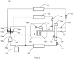
FIG. 2 shows a structural schematic diagram of an air conditioning system in a heating mode and a cooling and heat recovery mode. - The invention will be described in detail hereinafter with reference to the exemplary embodiments shown in the accompanying drawings. However, it should be appreciated that the invention can be implemented in many different forms, and should not be construed as being limited to the embodiments set forth herein. These embodiments are provided here for the purpose of making the specification more complete and comprehensive, and fully conveying the concept of the invention to those skilled in the art.
- Referring to
FIG. 1 , an embodiment of an air conditioning system is illustrated. Theair conditioning system 100 consists of afirst heat exchanger 101, asecond heat exchanger 102, athird heat exchanger 103, a four-way valve 104, acompressor 105, afirst throttling element 106 and asecond throttling element 107 with a shut-off function, areservoir 108, afirst solenoid valve 109, asecond solenoid valve 110, acheck valve 111, and other components. In practical applications, thefirst heat exchanger 101 can be a condenser and thethird heat exchanger 103 can be an evaporator, wherein both thefirst heat exchanger 101 and thethird heat exchanger 103 are water side heat exchangers with a water heat exchange structure inside, which can exchange heat with refrigerant or coolant to obtain cold or hot water accordingly. In addition, thesecond heat exchanger 102 can be a fan coil heat exchanger with one or more parallel fans, and at least one of the fans can be a variable frequency fan or a double speed fan, in order to enhance the heat exchange capacity and effect of thesecond heat exchanger 102. Thereservoir 108 is used to store excess refrigerant or coolant that does not participate in circulation in theair conditioning system 100. Specifically, the four-way valve 104 has afirst port 104a for communicating with theexhaust port 105a of thecompressor 105, asecond port 104b for communicating with the first end of thefirst heat exchanger 101, athird port 104c for communicating with the first end of thesecond heat exchanger 102, and afourth port 104d for communicating with the second end of thethird heat exchanger 103. In addition, the second end of thefirst heat exchanger 101 is connected to the first end of thereservoir 108 through thesecond solenoid valve 110, and at the same time, the second end of thefirst heat exchanger 101 is connected to the first end of thereservoir 108 through thecheck valve 111. The second end of thesecond heat exchanger 102 is connected to the second end of thereservoir 108 through thesecond throttling element 107. The first end of thethird heat exchanger 103 is connected to the first end of thereservoir 108 through thefirst solenoid valve 109, and at the same time the first end of thethird heat exchanger 103 is connected to the second end of thereservoir 108 through thefirst throttling element 106, and the second end of thethird heat exchanger 103 is connected to thesuction port 105b of thecompressor 105. The air conditioning system according to the invention can simplify pipeline design and reduce the number of valves, thereby achieving the goal of cost reduction and efficiency improvement. - It should be noted that both the
first throttling element 106 and thesecond throttling element 107 can play a role in throttling expansion. However, it can also be made that one is completely turned off, while the other can adjust its opening to play a role in throttling expansion. - In conjunction with the above embodiments, in other optional embodiments, the
air conditioning system 100 further comprises aneconomizer assembly 120, wherein theeconomizer assembly 120 is provided between thesecond throttling element 107 and the second end of thereservoir 108, and includes anintermediate heat exchanger 121 and a throttling bypass for throttling at least a portion of the refrigerant. The throttling bypass is provided with afilter 122 and athrottling device 123, wherein theintermediate heat exchanger 121 is communicated to the air replenishment port of thecompressor 105. In this case, thecompressor 105 can adopt an Enhanced Vapor Injection compressor to improve the overall operating range of theair conditioning system 100. - Various possible modifications of the air conditioning system will be described below in conjunction with the appended drawings. In addition, for the purpose of further improving system energy efficiency or reliability, additional components can be added, as will also be exemplarily illustrated below. For example, the
air conditioning system 100 further comprises a controller (not shown) that communicates with thefirst solenoid valve 109, thesecond solenoid valve 110, thefirst throttling element 106, thesecond throttling element 107, or any combination thereof. For example, theair conditioning system 100 also comprises a gas-liquid separator 112, which is located between thesuction port 105b of thecompressor 105 and the second end of thethird heat exchanger 103, thereby ensuring that thecompressor 105 does not carry liquid during operation. For another example, theair conditioning system 100 can be configured with afirst filter device 113, asecond filter device 114, athird filter device 115, etc. on the respective pipelines of theair conditioning system 100, in order to filter out oil droplets or other impurities carried by the refrigerant in the circulation system. - The
air conditioning system 100 can achieve a cooling mode. An illustrative example will be described below in conjunction withFIG. 1 - With continued reference to
FIG. 1 , specifically, when executing the cooling mode, the controller instructs to turn on thefirst solenoid valve 109, thesecond throttling element 107, thefirst port 104a and thethird port 104c of the four-way valve 104, and to turn off thefirst throttling element 106, thesecond solenoid valve 110, thesecond port 104b and thefourth port 104d of the four-way valve 104, so that thesecond throttling element 107 plays a throttling role. - The refrigerant of the
air conditioning system 100 first enters thecompressor 105 for gas-phase compression, and then flows from theexhaust port 105a of thecompressor 105 through thefirst port 104a of the four-way valve 104 and thethird port 104c of the four-way valve 104 into thesecond heat exchanger 102 for condensation and heat dissipation. Subsequently, the refrigerant flows into theeconomizer assembly 120 through thesecond throttling element 107, where the refrigerant can enter theeconomizer assembly 120 after undergoing throttling expansion in thesecond throttling element 107. At least a portion of the refrigerant is diverted from the main path of theeconomizer assembly 120 and enters the throttling bypass, passes sequentially through thefilter 122 and thethrottling device 123, enters theintermediate heat exchanger 121 after undergoing throttling expansion in thethrottling device 123 to exchange heat with the refrigerant on the main path of theeconomizer assembly 120, and then enters the intermediate stage of thecompressor 105 for air replenishment for thecompressor 105. When the remaining refrigerant flows out of the main path of theeconomizer assembly 120 into thereservoir 108, it then flows into thethird heat exchanger 103 through thefirst solenoid valve 109 for evaporation and heat absorption. When the refrigerant passes through thethird heat exchanger 103 and returns to thesuction port 105b of thecompressor 105, the cycle is completed. - For example, the
air conditioning system 100 can also achieve a heating mode. An illustrative example will be described below in conjunction withFIG. 2 . - With continued reference to
FIG. 2 , specifically, when executing the heating mode, the controller instructs to turn on thesecond throttling element 107 and instructs to communicate thefirst port 104a of the four-way valve 104 with thesecond port 104b of the four-way valve 104, and to communicate thethird port 104c of the four-way valve 104 with thefourth port 104d of the four-way valve 104, and to turn off thefirst throttling element 106, thefirst solenoid valve 109, and thesecond solenoid valve 110, so that thesecond throttling element 107 plays a throttling role. - The refrigerant of the
air conditioning system 100 first enters thecompressor 105 for gas-phase compression, and then flows from theexhaust port 105a of thecompressor 105 through thefirst port 104a of the four-way valve 104 and thesecond port 104b of the four-way valve 104 into thefirst heat exchanger 101 for condensation and heat dissipation. Subsequently, the refrigerant enters thereservoir 108 through thecheck valve 111, and flows from thereservoir 108 into theeconomizer assembly 120. At least a portion of the refrigerant is diverted from the main path of theeconomizer assembly 120 and enters the throttling bypass, passes sequentially through thefilter 122 and thethrottling device 123, enters theintermediate heat exchanger 121 after undergoing throttling expansion in thethrottling device 123 to exchange heat with the refrigerant on the main path of theeconomizer assembly 120, and then enters the intermediate stage of thecompressor 105 for air replenishment for thecompressor 105. When the remaining refrigerant flows out of the main path of theeconomizer assembly 120, it flows into thesecond heat exchanger 102 through thesecond throttling element 107, where the remaining refrigerant can enter thesecond heat exchanger 102 for evaporation and heat absorption after undergoing throttling expansion in thesecond throttling element 107. When the refrigerant passes through thesecond heat exchanger 102 and returns to thesuction port 105b of thecompressor 105 through thethird port 104c of the four-way valve 104 and thefourth port 104d of the four-way valve 104, the cycle is completed. - For example, the
air conditioning system 100 can also achieve a defrosting mode. An illustrative example will be described below in conjunction withFIG. 1 . - With continued reference to
FIG. 1 , specifically, when executing the defrosting mode, the controller instructs to turn on thesecond throttling element 107 and thesecond solenoid valve 110, and instructs to communicate thefirst port 104a of the four-way valve 104 with thethird port 104c of the four-way valve 104, and to communicate thesecond port 104b of the four-way valve 104 with thefourth port 104d of the four-way valve 104, and to turn off thefirst throttling element 106 and thefirst solenoid valve 109, so that thesecond throttling element 107 plays a throttling role. - The refrigerant of the
air conditioning system 100 first enters thecompressor 105 for gas-phase compression, and then flows from theexhaust port 105a of thecompressor 105 through thefirst port 104a of the four-way valve 104 and thethird port 104c of the four-way valve 104 into thesecond heat exchanger 102 for condensation and heat dissipation. Subsequently, the refrigerant flows into theeconomizer assembly 120 through thesecond throttling element 107, where the refrigerant can enter theeconomizer assembly 120 after undergoing throttling expansion in thesecond throttling element 107. At least a portion of the refrigerant is diverted from the main path of theeconomizer assembly 120 and enters the throttling bypass, passes sequentially through thefilter 122 and thethrottling device 123, enters theintermediate heat exchanger 121 after undergoing throttling expansion in thethrottling device 123 to exchange heat with the refrigerant on the main path of theeconomizer assembly 120, and then enters the intermediate stage of thecompressor 105 for air replenishment for thecompressor 105. When the remaining refrigerant flows out of the main path of theeconomizer assembly 120 into thereservoir 108, it then flows into thefirst heat exchanger 101 through thesecond solenoid valve 110 for evaporation and heat absorption. When the refrigerant passes through thefirst heat exchanger 101 and returns to thesuction port 105b of thecompressor 105 through thesecond port 104b of the four-way valve 104 and thefourth port 104d of the four-way valve 104, the cycle is completed. - For example, the
air conditioning system 100 can also achieve a cooling and heat recovery mode. An illustrative example will be described below in conjunction withFIG. 2 . - With continued reference to
FIG. 2 , specifically, when performing the cooling and heat recovery mode, the controller instructs to turn on thefirst throttling element 106, thefirst port 104a and thesecond port 104b of the four-way valve 104, and to turn off thesecond throttling element 107, thefirst solenoid valve 109, thesecond solenoid valve 110, and thethird port 104c and thefourth port 104d of the four-way valve 104, so that thefirst throttling element 106 plays a throttling role. - The refrigerant of the
air conditioning system 100 first enters thecompressor 105 for gas-phase compression, and then flows from theexhaust port 105a of thecompressor 105 through thefirst port 104a of the four-way valve 104 and thesecond port 104b of the four-way valve 104 into thefirst heat exchanger 101 for condensation and heat dissipation. Subsequently, the refrigerant passes through thecheck valve 111 and enters thereservoir 108. When the refrigerant flows out of thereservoir 108 and passes through thefirst throttling element 106, it flows into thethird heat exchanger 103, where the refrigerant can enter thethird heat exchanger 103 for evaporation and heat absorption after undergoing throttling expansion in thefirst throttling element 106. When the refrigerant passes through thethird heat exchanger 103 and returns to thesuction port 105b of thecompressor 105, the cycle is completed. In this case, thesecond heat exchanger 102 is in an idle state, and thefirst heat exchanger 101 can recover heat from the refrigerant or coolant to obtain corresponding hot water. - In the specification, it should be appreciated that the terms "first" and "second" are only used for descriptive purposes and cannot be construed as indicating or implying relative importance or implying the quantity of technical features indicated. Therefore, the features limited with "first" and "second" can explicitly or implicitly include at least one of these features. In the specification, "a plurality of" means at least two, such as two, three, etc., unless otherwise specified.
- In the specification, unless otherwise specified and limited, the terms "connect", "communicate" and other terms should be interpreted in a broad sense, which can be, for example, a fixed connection, a detachable connection, or integrally formed; or can be a direct connection or an indirect connection through an intermediate medium; or can be an internal communication of two components or the interaction relationship between two components, unless otherwise specified. For those skilled in the art, the specific meanings of the above terms in the specification can be interpreted based on specific circumstances.
- The above examples mainly illustrate an air conditioning system of the invention. Although only some embodiments of the invention have been described, those skilled in the art should be aware that the invention can be implemented in many other forms without deviating from its scope, which is as set out in the appended claims. Therefore, the examples and embodiments illustrated are considered as illustrative rather than restrictive. Without departing from the scope of the invention as defined in the appended claims, the invention may encompass various modifications and substitutions.
Claims (10)
- An air conditioning system (100), comprising:a compressor (105), a four-way valve (104), a first heat exchanger (101), a second heat exchanger (102), a third heat exchanger (103), a first throttling element (106) and a second throttling element (107) with a shut-off function, a reservoir (108), a first solenoid valve (109), a second solenoid valve (110), and a check valve (111) connected through pipelines,wherein the four-way valve (104) has a first port (104a) for communicating with an exhaust port (105a) of the compressor (105), a second port (104b) for communicating with a first end of the first heat exchanger (101), a third port (104c) for communicating with a first end of the second heat exchanger (102), and a fourth port (104d) for communicating with a second end of the third heat exchanger (103);wherein a second end of the first heat exchanger (101) is connected to a first end of the reservoir (108) through the second solenoid valve (110), and at the same time the second end of the first heat exchanger (101) is connected to the first end of the reservoir (108) through the check valve (111); a second end of the second heat exchanger (102) is connected to a second end of the reservoir (108) through the second throttling element (107); a first end of the third heat exchanger (103) is connected to the first end of the reservoir (108) through the first solenoid valve (109), and at the same time the first end of the third heat exchanger (103) is connected to the second end of the reservoir (108) through the first throttling element (106), and the second end of the third heat exchanger (103) is connected to a suction port (105b) of the compressor (105).
- The air conditioning system (100) according to claim 1, wherein the air conditioning system further comprises an economizer assembly (120) provided between the second throttling element (107) and the second end of the reservoir (108), and comprising an intermediate heat exchanger (121) and a throttling bypass for throttling at least a portion of refrigerant, where the throttling bypass is provided with a throttling device (123), and the intermediate heat exchanger is communicated to an air replenishment port of the compressor (105).
- The air conditioning system (100) according to claim 2, where the air conditioning system further comprises a controller that communicates with the first solenoid valve (109), the second solenoid valve (110), the first throttling element (106), the second throttling element (107), or any combination thereof.
- The air conditioning system (100) according to claim 3, wherein the air conditioning system has a cooling mode, wherein the controller instructs to turn on the first solenoid valve (109), the second throttling element (107), and a first port (104a) and a third port (104c) of the four-way valve (104), and to turn off the first throttling element (106), the second solenoid valve (110), and a second port (104b) and a fourth port (104d) of the four-way valve (104), so that the second throttling element (107) plays a throttling role, thereby allowing the refrigerant of the air conditioning system to sequentially flow through the exhaust port (105a) of the compressor (105), the first port (104a) of the four-way valve (104), the third port (104c) of the four-way valve (104), the second heat exchanger (102), the second throttling element (107), the economizer assembly (120), the reservoir (108), the first solenoid valve (109), the third heat exchanger (103), and the suction port (105b) of the compressor (105).
- The air conditioning system (100) according to claim 3, wherein the air conditioning system (100) has a heating mode, wherein the controller instructs to turn on the second throttling element (107) and instructs to communicate the first port (104a) of the four-way valve (104) with the second port (104b) of the four-way valve (104) and to communicate the third port (104c) of the four-way valve (104) with the fourth port (104d) of the four-way valve (104), and to turn off the first throttling element (106), the first solenoid valve (109), and the second solenoid valve (110), so that the second throttling element (107) plays a throttling role, thereby allowing the refrigerant of the air conditioning system to sequentially flow through the exhaust port (105a) of the compressor (105), the first port (104a) of the four-way valve (104), the second port (104b) of the four-way valve (104), the first heat exchanger (101), the check valve (111), the reservoir (108), the economizer assembly (120), the second throttling element (107), the second heat exchanger (102), the third port (104c) of the four-way valve (104), the fourth port (104d) of the four-way valve (104), and the suction port (105b) of the compressor (105).
- The air conditioning system (100) according to claim 3, wherein the air conditioning system has a defrosting mode, wherein the controller instructs to turn on the second throttling element (107) and the second solenoid valve (110), and instructs to communicate the first port (104a) of the four-way valve (104) with the third port (104c) of the four-way valve (104) and to communicate the second port (104b) of the four-way valve (104) with the fourth port (104d) of the four-way valve (104), and to turn off the first throttling element (106) and the first solenoid valve (109), so that the second throttling element (107) plays a throttling role, thereby allowing the refrigerant of the air conditioning system to sequentially flow through the exhaust port (105a) of the compressor (105), the first port (104a) of the four-way valve (104), the third port (104c) of the four-way valve (104), the second heat exchanger (102), the second throttling element (107), the economizer assembly (120), the reservoir (108), the second solenoid valve (110), the first heat exchanger (101), the second port (104b) of the four-way valve (104), the fourth port (104d) of the four-way valve (104), and the suction port (105b) of the compressor (105).
- The air conditioning system (100) according to claim 3, wherein the air conditioning system has a cooling and heat recovery mode, wherein the controller instructs to turn on the first throttling element (106), the first port (104a) and the second port (104b) of the four-way valve (104), and to turn off the second throttling element (107), the first solenoid valve (109), the second solenoid valve (110), the third port (104c) and the fourth port (104d) of the four-way valve (104), so that the first throttling element (106) plays a throttling role, thereby allowing the refrigerant of the air conditioning system to sequentially flow through the exhaust port (105a) of the compressor (105), the first port (104a) of the four-way valve (104), the second port (104b) of the four-way valve (104), the first heat exchanger (101), the check valve (111), the reservoir (108), the first throttling element (106), the third heat exchanger (103), and the suction port (105b) of compressor (105).
- The air conditioning system (100) according to any preceding claim, wherein the compressor (105) is an Enhanced Vapor Injection compressor.
- The air conditioning system (100) according to any preceding claim, wherein the air conditioning system further comprises a gas-liquid separator (112) provided between the suction port (105b) of the compressor (105) and the second end of the third heat exchanger (103).
- The air conditioning system according to any preceding claim, wherein the second heat exchanger (102) is a fan coil heat exchanger.
Applications Claiming Priority (1)
| Application Number | Priority Date | Filing Date | Title |
|---|---|---|---|
| CN202310923964.2A CN119374219A (en) | 2023-07-25 | 2023-07-25 | Air conditioning system |
Publications (1)
| Publication Number | Publication Date |
|---|---|
| EP4498021A1 true EP4498021A1 (en) | 2025-01-29 |
Family
ID=91959120
Family Applications (1)
| Application Number | Title | Priority Date | Filing Date |
|---|---|---|---|
| EP24189259.5A Pending EP4498021A1 (en) | 2023-07-25 | 2024-07-17 | Air conditioning system |
Country Status (3)
| Country | Link |
|---|---|
| US (1) | US20250035331A1 (en) |
| EP (1) | EP4498021A1 (en) |
| CN (1) | CN119374219A (en) |
Citations (5)
| Publication number | Priority date | Publication date | Assignee | Title |
|---|---|---|---|---|
| CN108931069A (en) * | 2018-06-05 | 2018-12-04 | 珠海英伟特电子科技有限公司 | Air conditioner and water heater and its control method |
| US20190226726A1 (en) * | 2018-01-19 | 2019-07-25 | Arctic Cool Chillers Limited | Apparatuses and methods for modular heating and cooling system |
| US20200240680A1 (en) * | 2017-09-30 | 2020-07-30 | York (Wuxi) Air Conditioning And Refrigeration Co., Ltd. | Heat pump unit and the control method thereof |
| US20220034565A1 (en) * | 2020-07-31 | 2022-02-03 | Carrier Corporation | Heat pump system and control method thereof |
| US20220290905A1 (en) * | 2020-06-30 | 2022-09-15 | Trane International Inc. | Superheating control for heating, ventilation, air conditioning and refrigeration (hvacr) system including a dynamic receiver |
Family Cites Families (50)
| Publication number | Priority date | Publication date | Assignee | Title |
|---|---|---|---|---|
| US3063251A (en) * | 1959-10-23 | 1962-11-13 | Borg Warner | Starting relay system for heat pumps |
| US3209814A (en) * | 1963-04-03 | 1965-10-05 | Transicold Corp | Refrigeration system |
| US4055963A (en) * | 1975-06-25 | 1977-11-01 | Daikin Kogyo Co., Ltd. | Heating system |
| US4197719A (en) * | 1976-01-29 | 1980-04-15 | Dunham-Bush, Inc. | Tri-level multi-cylinder reciprocating compressor heat pump system |
| US4030312A (en) * | 1976-04-07 | 1977-06-21 | Shantzer-Wallin Corporation | Heat pumps with solar heat source |
| US4299098A (en) * | 1980-07-10 | 1981-11-10 | The Trane Company | Refrigeration circuit for heat pump water heater and control therefor |
| JPS588956A (en) * | 1981-07-10 | 1983-01-19 | 株式会社システム・ホ−ムズ | Heat pump type air conditioner |
| US4399664A (en) * | 1981-12-07 | 1983-08-23 | The Trane Company | Heat pump water heater circuit |
| US4644756A (en) * | 1983-12-21 | 1987-02-24 | Daikin Industries, Ltd. | Multi-room type air conditioner |
| US4643002A (en) * | 1985-09-26 | 1987-02-17 | Carrier Corporation | Continuous metered flow multizone air conditioning system |
| US4646538A (en) * | 1986-02-10 | 1987-03-03 | Mississipi Power Co. | Triple integrated heat pump system |
| AU581569B2 (en) * | 1986-06-06 | 1989-02-23 | Mitsubishi Denki Kabushiki Kaisha | Multiroom air conditioner |
| JP2504437B2 (en) * | 1987-01-30 | 1996-06-05 | 株式会社東芝 | air conditioner |
| US5109677A (en) * | 1991-02-21 | 1992-05-05 | Gary Phillippe | Supplemental heat exchanger system for heat pump |
| US5140827A (en) * | 1991-05-14 | 1992-08-25 | Electric Power Research Institute, Inc. | Automatic refrigerant charge variation means |
| US5186012A (en) * | 1991-09-24 | 1993-02-16 | Institute Of Gas Technology | Refrigerant composition control system for use in heat pumps using non-azeotropic refrigerant mixtures |
| US5388419A (en) * | 1993-04-23 | 1995-02-14 | Maritime Geothermal Ltd. | Staged cooling direct expansion geothermal heat pump |
| EP0800940A3 (en) * | 1996-04-10 | 2001-06-06 | Denso Corporation | Vehicular air conditioning system for electric vehicles |
| KR100389271B1 (en) * | 2001-03-17 | 2003-06-27 | 진금수 | Heat pump apparatus |
| KR100402366B1 (en) * | 2001-08-31 | 2003-10-17 | 진금수 | Heat pump system |
| US7299649B2 (en) * | 2003-12-09 | 2007-11-27 | Emerson Climate Technologies, Inc. | Vapor injection system |
| CA2510701C (en) * | 2005-06-27 | 2008-12-16 | Geofurnace Development Inc. | Hybrid heating and cooling system |
| JP2007139241A (en) * | 2005-11-16 | 2007-06-07 | Hitachi Ltd | Air conditioner |
| DE102006026359B4 (en) * | 2006-05-31 | 2010-06-17 | Visteon Global Technologies Inc., Van Buren | Air conditioning for vehicles |
| JP5236009B2 (en) * | 2008-10-29 | 2013-07-17 | 三菱電機株式会社 | Air conditioner |
| WO2012160597A1 (en) * | 2011-05-23 | 2012-11-29 | 三菱電機株式会社 | Air conditioning device |
| US9513036B2 (en) * | 2011-06-16 | 2016-12-06 | Mitsubishi Electric Corporation | Air-conditioning apparatus |
| EP2610559A2 (en) * | 2012-01-02 | 2013-07-03 | Samsung Electronics Co., Ltd | Heat pump and control method thereof |
| US9316421B2 (en) * | 2012-08-02 | 2016-04-19 | Mitsubishi Electric Corporation | Air-conditioning apparatus including unit for increasing heating capacity |
| CN105074352B (en) * | 2013-02-25 | 2017-07-07 | 三菱电机株式会社 | air conditioner |
| CN104374115A (en) * | 2013-08-14 | 2015-02-25 | 开利公司 | Heat pump system, heat pump unit and a multifunctional mode control method for heat pump system |
| US20150267951A1 (en) * | 2014-03-21 | 2015-09-24 | Lennox Industries Inc. | Variable refrigerant charge control |
| CN105757798B (en) * | 2016-03-03 | 2018-11-27 | 美的集团武汉制冷设备有限公司 | The control method of air-conditioning system and air-conditioning system |
| CN105627615B (en) * | 2016-03-03 | 2018-11-27 | 广东美的制冷设备有限公司 | The control method of air-conditioning system and air-conditioning system |
| CN109386989B (en) * | 2018-10-22 | 2020-07-28 | 广东美的暖通设备有限公司 | Two-pipe jet enthalpy-increasing outdoor unit and multi-split system |
| CN109386985B (en) * | 2018-10-22 | 2020-07-28 | 广东美的暖通设备有限公司 | Two-pipe jet enthalpy increasing outdoor unit and multi-connection system |
| CN109386983B (en) * | 2018-10-22 | 2020-07-28 | 广东美的暖通设备有限公司 | Two-pipe jet enthalpy increasing outdoor unit and multi-connection system |
| CN111912056A (en) * | 2019-05-07 | 2020-11-10 | 开利公司 | Air conditioning system |
| CN111907301B (en) * | 2019-05-07 | 2024-10-25 | 开利公司 | Combined heat exchanger, heat exchange system and optimization method thereof |
| JPWO2021019687A1 (en) * | 2019-07-30 | 2021-02-04 | ||
| CN214666271U (en) * | 2020-08-26 | 2021-11-09 | 广东美的暖通设备有限公司 | Heat exchanger, electric control box and air conditioning system |
| WO2022079763A1 (en) * | 2020-10-12 | 2022-04-21 | 三菱電機株式会社 | Refrigeration cycle device, air conditioner, and heat exchanger |
| CN114909715B (en) * | 2021-02-08 | 2024-03-22 | 广东美的暖通设备有限公司 | Heat exchanger, manufacturing method thereof, electric control box and air conditioning system |
| CN114909831B (en) * | 2021-02-08 | 2024-06-14 | 广东美的暖通设备有限公司 | Heat exchanger, electric control box and air conditioning system |
| CN116533706A (en) * | 2022-01-26 | 2023-08-04 | 开利公司 | Multi-temperature-zone air conditioning system, control method thereof and transport refrigeration vehicle |
| CN116625020A (en) * | 2022-02-11 | 2023-08-22 | 开利公司 | Refrigeration system and control method thereof |
| CN116792970A (en) * | 2022-03-18 | 2023-09-22 | 开利公司 | Heat pump system and control method thereof |
| CN117146343A (en) * | 2022-05-24 | 2023-12-01 | 开利公司 | Heat pump system and control method |
| DE102022128613A1 (en) * | 2022-10-28 | 2024-05-08 | Ford Global Technologies, Llc | Thermal management system with secondary circuit |
| US20240344734A1 (en) * | 2023-04-11 | 2024-10-17 | Carrier Corporation | Refrigerant flow management for modulating reheat system |
-
2023
- 2023-07-25 CN CN202310923964.2A patent/CN119374219A/en active Pending
-
2024
- 2024-07-11 US US18/769,729 patent/US20250035331A1/en active Pending
- 2024-07-17 EP EP24189259.5A patent/EP4498021A1/en active Pending
Patent Citations (5)
| Publication number | Priority date | Publication date | Assignee | Title |
|---|---|---|---|---|
| US20200240680A1 (en) * | 2017-09-30 | 2020-07-30 | York (Wuxi) Air Conditioning And Refrigeration Co., Ltd. | Heat pump unit and the control method thereof |
| US20190226726A1 (en) * | 2018-01-19 | 2019-07-25 | Arctic Cool Chillers Limited | Apparatuses and methods for modular heating and cooling system |
| CN108931069A (en) * | 2018-06-05 | 2018-12-04 | 珠海英伟特电子科技有限公司 | Air conditioner and water heater and its control method |
| US20220290905A1 (en) * | 2020-06-30 | 2022-09-15 | Trane International Inc. | Superheating control for heating, ventilation, air conditioning and refrigeration (hvacr) system including a dynamic receiver |
| US20220034565A1 (en) * | 2020-07-31 | 2022-02-03 | Carrier Corporation | Heat pump system and control method thereof |
Also Published As
| Publication number | Publication date |
|---|---|
| US20250035331A1 (en) | 2025-01-30 |
| CN119374219A (en) | 2025-01-28 |
Similar Documents
| Publication | Publication Date | Title |
|---|---|---|
| CN207299635U (en) | For multi-line system outdoor unit and there is its multi-line system | |
| CN103175344B (en) | Cold-region used multi-connected heat pump system and control method thereof | |
| CN114838535B (en) | Air conditioning system with bypass heating gas-liquid separator and heating method thereof | |
| CN108332285A (en) | Air-conditioner system | |
| EP3736513B1 (en) | Circulation system for air conditioner and air conditioner | |
| CN215638160U (en) | Air conditioner heat exchange system and air conditioner | |
| CN108759138B (en) | Operation method and system of secondary throttling middle incomplete cooling refrigerating system | |
| CN201407856Y (en) | A dual-temperature refrigeration cycle system | |
| CN109386985B (en) | Two-pipe jet enthalpy increasing outdoor unit and multi-connection system | |
| CN102759147B (en) | Air-conditioning multiple on-line system | |
| CN105333641B (en) | Air-source air conditioning and water heating system | |
| CN215951838U (en) | Refrigerating system and household appliance | |
| CN222978384U (en) | A multifunctional and efficient defrosting evaporative cooling and heat pump unit | |
| CN106949657B (en) | Air conditioning system with supercooling device and control method thereof | |
| CN114111110A (en) | Heat pump system with plate for exchanging supercooling | |
| CN219955525U (en) | Sewage source magnetic suspension centrifugal multi-split air conditioning system | |
| CN220871097U (en) | Thermal energy storage system | |
| US20250035331A1 (en) | Air conditioning system | |
| CN108088008B (en) | Multi-split air conditioner and heat recovery system thereof | |
| CN115638574B (en) | Fluorine pump multi-connected refrigerating system and control method thereof | |
| CN215930176U (en) | Refrigerating system | |
| CN117329610A (en) | Air conditioning system and air conditioning system load matching control method | |
| CN112013566B (en) | Energy-saving multifunctional heat pump integrating energy | |
| CN108375255A (en) | Air-conditioner system | |
| CN224175363U (en) | Air conditioning system |
Legal Events
| Date | Code | Title | Description |
|---|---|---|---|
| PUAI | Public reference made under article 153(3) epc to a published international application that has entered the european phase |
Free format text: ORIGINAL CODE: 0009012 |
|
| STAA | Information on the status of an ep patent application or granted ep patent |
Free format text: STATUS: THE APPLICATION HAS BEEN PUBLISHED |
|
| AK | Designated contracting states |
Kind code of ref document: A1 Designated state(s): AL AT BE BG CH CY CZ DE DK EE ES FI FR GB GR HR HU IE IS IT LI LT LU LV MC ME MK MT NL NO PL PT RO RS SE SI SK SM TR |
|
| STAA | Information on the status of an ep patent application or granted ep patent |
Free format text: STATUS: REQUEST FOR EXAMINATION WAS MADE |
|
| 17P | Request for examination filed |
Effective date: 20250305 |