EP4497838A1 - Blast furnace operation method - Google Patents
Blast furnace operation method Download PDFInfo
- Publication number
- EP4497838A1 EP4497838A1 EP23807337.3A EP23807337A EP4497838A1 EP 4497838 A1 EP4497838 A1 EP 4497838A1 EP 23807337 A EP23807337 A EP 23807337A EP 4497838 A1 EP4497838 A1 EP 4497838A1
- Authority
- EP
- European Patent Office
- Prior art keywords
- hole
- blast furnace
- furnace
- melt
- blasting
- Prior art date
- Legal status (The legal status is an assumption and is not a legal conclusion. Google has not performed a legal analysis and makes no representation as to the accuracy of the status listed.)
- Pending
Links
Images


Classifications
-
- C—CHEMISTRY; METALLURGY
- C21—METALLURGY OF IRON
- C21B—MANUFACTURE OF IRON OR STEEL
- C21B7/00—Blast furnaces
- C21B7/12—Opening or sealing the tap holes
-
- F—MECHANICAL ENGINEERING; LIGHTING; HEATING; WEAPONS; BLASTING
- F27—FURNACES; KILNS; OVENS; RETORTS
- F27B—FURNACES, KILNS, OVENS OR RETORTS IN GENERAL; OPEN SINTERING OR LIKE APPARATUS
- F27B1/00—Shaft or like vertical or substantially vertical furnaces
- F27B1/10—Details, accessories or equipment specially adapted for furnaces of these types
- F27B1/21—Arrangements of devices for discharging
-
- F—MECHANICAL ENGINEERING; LIGHTING; HEATING; WEAPONS; BLASTING
- F27—FURNACES; KILNS; OVENS; RETORTS
- F27D—DETAILS OR ACCESSORIES OF FURNACES, KILNS, OVENS OR RETORTS, IN SO FAR AS THEY ARE OF KINDS OCCURRING IN MORE THAN ONE KIND OF FURNACE
- F27D3/00—Charging; Discharging; Manipulation of charge
- F27D3/15—Tapping equipment; Equipment for removing or retaining slag
- F27D3/1509—Tapping equipment
- F27D3/1527—Taphole forming equipment, e.g. boring machines, piercing tools
Definitions
- the present invention relates to a blast furnace operation method for restarting blasting after the blasting of a blast furnace is stopped upon operation shutdown.
- the blasting may be stopped for a period of time to allow molten pig iron slag to solidify in the furnace.
- banking there is a known technology called banking in which blasting is stopped for an extended period of time.
- Patent Literature 1 discloses a method for extracting molten pig iron at the bottom of the furnace by tapping the molten pig iron from a furnace-bottom tap hole provided in a wall portion of the furnace at a level lower than the ordinary tap hole when blasting is ended.
- Patent Literature 2 discloses a method for providing an opening in the lower wall of the furnace after blasting is ended and then removing from the furnace a residue at the furnace bottom remaining on the entire bottom surface of the furnace.
- Patent Literature 1 and Patent Literature 2 have a problem that since a furnace-bottom tap hole or an opening is provided at a level lower than the respective tap hole, carbon bricks, which are the bottom bricks of the furnace, would suffer wear damage.
- the present invention aims to solve such problems and provides a blast furnace operation method that can reduce the amount of melt remaining in a blast furnace before stopping blasting more than the conventional blast furnace operation method, without subjecting carbon bricks to wear damage.
- a blast furnace operation method of the present invention has been developed to solve the above problems, and is a blast furnace operation method restarting blasting after the blasting of a blast furnace is stopped.
- the furnace inner wall at a bottom of the blast furnace has a mud material closing a tap hole at a position where a through-hole is to be opened, and carbon bricks lining other portions.
- the blast furnace operation method includes, during reduced operation of the blast furnace before stopping blasting, in a portion where the mud material is provided in the tap hole, opening the through-hole such that a lower end of an opening on the furnace inner wall surface of the through-hole is located at a position lower than a lower end of an opening on the furnace inner wall surface of a through-hole during normal operation; and discharging a melt through the through-hole.
- blast furnace operation method of the present invention may include the following as a solution means that is considered to be more preferable.
- the blast furnace operation method of the present invention it is possible to reduce the amount of solidified melt remaining in a blast furnace after blasting is stopped without damaging bottom bricks of the furnace. This can reduce a temperature drop of a melt that is obtained when the blast furnace is restarted, and thus can achieve a smoother restart of the blast furnace.
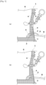
- Figs. 1(a) and 1(b) are schematic cross-sectional views each showing the state of a tap hole during normal operation of a blast furnace.
- Figs. 1(a) and 1(b) each show part of the bottom of a blast furnace 1.
- a furnace inner wall at the bottom of the blast furnace includes a mud material 3 closing a tap hole 2 at a position where a through-hole 7 is to be opened, and carbon bricks 4 lining the other portions.
- Reference sign 5 denotes a tuyere.
- the blast furnace 1 typically includes a plurality of tap holes 2, for example, four tap holes 2. Normal operation of the blast furnace is performed by alternately using the tap holes 2. Specifically, when attention is paid to a single tap hole 2, the through-hole 7 is provided in the mud material 3 closing the tap hole 2 so as to connect the outside of the furnace to the inside of the furnace, whereby a melt 6 in the furnace is tapped through the through-hole 7, as shown in Fig. 1(a) . Meanwhile, as shown in Fig. 1(b) , another tap hole 2 through which the melt 6 in the furnace is not to be tapped is closed with the mud material 3 so that the melt 6 in the furnace is not discharged to the outside of the furnace through the tap hole 2.
- reference sign 8 denotes a tap gutter for delivering the melt 6 tapped from the furnace to the outside of the furnace.
- Fig. 3 is a schematic cross-sectional view for describing a state immediately before the end of reduced operation when the blast furnace operation method according to the present invention is performed.
- the melt 6 slag 6a and molten pig iron 6b
- Such a solidified melt would carry heat away from molten pig iron that is produced when blasting is restarted, which would lower the temperature of the melt and reduce the fluidity of the melt, disturbing a smooth restart of the furnace.
- Fig. 4 is a schematic cross-sectional view showing a method for opening a tap hole in the blast furnace operation method according to the present invention.
- a solid line represents a method of opening a through-hole 7 during tapping performed in normal operation by directing a rod of a drilling machine 11 toward the center of the mud material 3 in the tap hole 2.
- a broken line and a dashed and single-dotted line both represent a method of opening a through-hole 7 during reduced operation before blasting is stopped when the blast furnace operation method according to the present invention is performed, by inserting the rod of the drilling machine 11 through the mud material 3 in the tap hole 2 such that the opened through-hole 7 is located at a position lower than the through-hole 7 opened during normal operation.
- the example indicated by the broken line shows a state in which the carbon bricks 4 forming the tap hole 2 is hardly worn off when a hole is opened during reduced operation.
- the example indicated by the single-dotted line shows a state in which the carbon bricks 4 forming the tap hole 2 is worn off when a hole is opened during reduced operation.
- the carbon bricks 4 is worn off by about 0.1°/year from the blowing-in to reduced operation.
- the through-hole 7 is opened with the rod of the drilling machine 11 by setting the angle of the through-hole 7 to the mud material 3 in the tap hole 2 to 10°.
- the through-hole 7 is opened with the rod of the drilling machine 11 by setting the angle of the through-hole 7 to the mud material 3 in the tap hole 2 to 13.8°.
- the through-hole 7 is opened with the rod of the drilling machine 11 by setting the angle of the through-hole 7 to the mud material 3 in the tap hole 2 to 15°.
- Table 1 below shows the surface level of the melt 6, a drop in the surface level, the volume of the melt that has decreased, and the mass of the melt that has decreased when the angle of inclination of the through-hole 7 is changed.
- a through-hole angle of 10° indicates the angle of inclination of the through-hole 7 opened during normal operation.
- through-hole angles of 13.8° and 15° each correspond to the angle of inclination that allows the lower end 7a of the through-hole 7 to be located at the lower end of the tap hole 2 provided with the mud material 3 on the inner side of the furnace.
- the through-hole 7 As shown in Table 1, as the angle of the through-hole 7 is increased to lower the lower end position 7a of the through-hole 7, the surface level of the melt decreases, thus reducing the volume and mass of the melt 6 remaining in the furnace.
- the lower limit of the lower end position 7a of the through-hole 7 corresponds to the lower end of the tap hole 2 provided with the mud material 3 on the inside of the furnace.
- the through-hole 7 is preferably provided such that the lower end position 7a of the through-hole 7 is located at the lower end position of the tap hole 2 provided with the mud material 3 on the inner side of the furnace. This can minimize the melt 6 remaining in the furnace within the range in which the carbon bricks 4 do not break.
- the angle of the through-hole 7 opened during reduced operation in the blast furnace operation method of the present invention is preferably set to 13.8° to 15°.
- the blast pressure from the tuyere 5 of the blast furnace before reducing the operation is preferably 150 to 250 kPa.
- the level of the melt 6 inside the furnace is lower than the position of the through-hole 7 on the outer surface of the furnace.
- the melt 6 in the furnace is discharged via the through-hole 7 due to the pressure difference between high pressure (blast pressure) in the furnace and the atmospheric pressure. Therefore, it is preferable to set the blast pressure from the tuyere 5 of the blast furnace to 150 kPa or more to increase pressure in the furnace, and thus increase the pressure difference. This allows a further larger amount of the melt 6 to be discharged via the through-hole 7. Meanwhile, if the blast pressure is increased too much, the blast flow rate increases, increasing the amount of melt to be produced, which is unfavorable.
- the blast pressure through the tuyere 5 of the blast furnace is preferably 250 kPa or less.
- a blast furnace basically includes four tap holes.
- the number of tap holes that are used among the four tap holes is basically two, or three at most.
- the plurality of tap holes can be opened in the following order, for example.
- the time intervals for opening tap holes are not limited to a particular time, either, and are determined in accordance with the condition of the furnace and the volume of air at that time. Therefore, the time intervals for opening tap holes may vary, such as 5 minutes, 10 minutes, and 1 hour, and thus are not limited to a particular time.
- blast furnace operation method it is possible to not only restart a blast furnace, but also provide a stable operation method for various vertical melting furnaces including those other than the blast furnace.
Landscapes
- Engineering & Computer Science (AREA)
- Mechanical Engineering (AREA)
- General Engineering & Computer Science (AREA)
- Chemical & Material Sciences (AREA)
- Manufacturing & Machinery (AREA)
- Materials Engineering (AREA)
- Metallurgy (AREA)
- Organic Chemistry (AREA)
- Furnace Charging Or Discharging (AREA)
- Blast Furnaces (AREA)
Abstract

Description
- The present invention relates to a blast furnace operation method for restarting blasting after the blasting of a blast furnace is stopped upon operation shutdown.
- When a blast furnace is forced to reduce the production of molten pig iron, the blasting rate is reduced. This may bring the furnace into a poor condition due to the inactivation of the furnace core. If the tapping ratio has become less than 1.5 due to a reduction in the production of molten pig iron, the operation will be continued at a coke ratio of over 400 kg/t. However, this is not economically reasonable since coke is an expensive raw material. Further, since the downward elasticity of the production of a blast furnace is limited, there may be cases where the operation of the blast furnace needs to be stopped when the furnace is forced to significantly reduce the production of molten pig iron. In addition, to repair worn auxiliary equipment for a blast furnace, the blasting may be stopped for a period of time to allow molten pig iron slag to solidify in the furnace. To respond to such situations, there is a known technology called banking in which blasting is stopped for an extended period of time.
- When banking is performed, it is necessary to lower the stock line of a raw material to the level of a tuyere and cool the residual coke and the residual iron slag within the furnace to room temperature (for three months) as a preparation for blasting, and then load heavy equipment into the furnace for performing the operations of removing the residual coke and laying coke and sleepers inside the furnace (for 2.5 months). Thus, the furnace operation should be suspended for a period of at least 5.5 months. Therefore, it would be impossible to rapidly recover steel demand, or perform middle-stage repair work that is limited by the construction period, and thus adjust production to respond to the trend in steel demand.
- As a technology for shortening the suspension period of a blast furnace, Patent Literature 1 discloses a method for extracting molten pig iron at the bottom of the furnace by tapping the molten pig iron from a furnace-bottom tap hole provided in a wall portion of the furnace at a level lower than the ordinary tap hole when blasting is ended. Meanwhile,
Patent Literature 2 discloses a method for providing an opening in the lower wall of the furnace after blasting is ended and then removing from the furnace a residue at the furnace bottom remaining on the entire bottom surface of the furnace. -
- Patent Literature 1:
JP-2006-137985A - Patent Literature 2:
JP-H07-197112A - However, each of the technologies disclosed in Patent Literature 1 and
Patent Literature 2 has a problem that since a furnace-bottom tap hole or an opening is provided at a level lower than the respective tap hole, carbon bricks, which are the bottom bricks of the furnace, would suffer wear damage. - The present invention aims to solve such problems and provides a blast furnace operation method that can reduce the amount of melt remaining in a blast furnace before stopping blasting more than the conventional blast furnace operation method, without subjecting carbon bricks to wear damage.
- A blast furnace operation method of the present invention has been developed to solve the above problems, and is a blast furnace operation method restarting blasting after the blasting of a blast furnace is stopped. The furnace inner wall at a bottom of the blast furnace has a mud material closing a tap hole at a position where a through-hole is to be opened, and carbon bricks lining other portions. The blast furnace operation method includes, during reduced operation of the blast furnace before stopping blasting, in a portion where the mud material is provided in the tap hole, opening the through-hole such that a lower end of an opening on the furnace inner wall surface of the through-hole is located at a position lower than a lower end of an opening on the furnace inner wall surface of a through-hole during normal operation; and discharging a melt through the through-hole.
- Note that the blast furnace operation method of the present invention may include the following as a solution means that is considered to be more preferable.
- (1) A plurality of tap holes are provided in a circumferential direction of a lower portion of the blast furnace, and the method includes, during reduced operation before stopping blasting, sequentially opening through-holes each of which has been closed with the mud material during normal operation such that the lower end of an opening on the furnace inner wall surface of the through-hole is located at a position lower than a lower end of an opening on the furnace inner wall surface of a through-hole opened during normal operation.
- (2) Opening the through-hole so as to allow the lower end of the opening on the furnace inner wall surface of the through-hole to be located at a lower end of the tap hole on the inner wall surface side where the mud material is provided.
- (3) Setting an angle of inclination of the through-hole to be larger than an angle of inclination of the through-hole during normal operation.
- (4) Setting a blast pressure through a tuyere to 150 to 250 kPa so as to discharge the melt from the through-hole.
- (5) After discharging the melt through the through-hole before stopping blasting, closing the through-hole with the mud material to stop blasting and opening a through-hole at a position for normal operation when restarting blasting to discharge a melt in the furnace through the through-hole, thereby suppressing a temperature drop of the melt when restarting blasting.
- According to the blast furnace operation method of the present invention, it is possible to reduce the amount of solidified melt remaining in a blast furnace after blasting is stopped without damaging bottom bricks of the furnace. This can reduce a temperature drop of a melt that is obtained when the blast furnace is restarted, and thus can achieve a smoother restart of the blast furnace.
-
- [
Fig. 1] Figs. 1(a) and 1(b) are schematic cross-sectional views each showing the state of a tap hole during normal operation of a blast furnace. - [
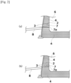
Fig. 2] Figs. 2(a) and 2(b) are schematic cross-sectional views each showing the state of a tap hole when a blast furnace operation method according to the present invention is performed. - [
Fig. 3] Fig. 3 is a schematic cross-sectional view for describing a state immediately before the end of a burden stock line lowering operation when the blast furnace operation method according to the present invention is performed. - [
Fig. 4] Fig. 4 is a schematic cross-sectional view for describing a method for opening a tap hole in the blast furnace operation method according to the present invention. - Hereinafter, an embodiment of the present invention will be specifically described. Note that the following embodiment only illustrates examples of an apparatus and a method for embodying the technical idea of the present invention. Thus, the configuration of the present invention is not limited thereto. That is, the technical idea of the present invention can be changed in various ways within the technical scope recited in the claims. In the following embodiment, an example of a blast furnace operation method that is a target of the present invention will be described first, and then, the features of the blast furnace operation method of the present invention will be described.
-
Figs. 1(a) and 1(b) are schematic cross-sectional views each showing the state of a tap hole during normal operation of a blast furnace.Figs. 1(a) and 1(b) each show part of the bottom of a blast furnace 1. A furnace inner wall at the bottom of the blast furnace includes amud material 3 closing atap hole 2 at a position where a through-hole 7 is to be opened, andcarbon bricks 4 lining the other portions.Reference sign 5 denotes a tuyere. - The blast furnace 1 typically includes a plurality of
tap holes 2, for example, fourtap holes 2. Normal operation of the blast furnace is performed by alternately using thetap holes 2. Specifically, when attention is paid to asingle tap hole 2, the through-hole 7 is provided in themud material 3 closing thetap hole 2 so as to connect the outside of the furnace to the inside of the furnace, whereby amelt 6 in the furnace is tapped through the through-hole 7, as shown inFig. 1(a) . Meanwhile, as shown inFig. 1(b) , anothertap hole 2 through which themelt 6 in the furnace is not to be tapped is closed with themud material 3 so that themelt 6 in the furnace is not discharged to the outside of the furnace through thetap hole 2. After the completion of the tapping of themelt 6 in the furnace, thetap hole 2 is closed again with themud material 3. Normal operation of the blast furnace is performed by repeating the operation continuously. It should be noted thatreference sign 8 denotes a tap gutter for delivering themelt 6 tapped from the furnace to the outside of the furnace. - When blasting is suspended for a long period (hereinafter also referred to as banking) to reduce the steel production or carry out repairs in the blast furnace 1, reduced operation is performed to lower the stock line of the raw material (melt 6) to the level of the
tuyere 5, for example. In the blast furnace operation according to this embodiment, during reduced operation before blasting is stopped, in a portion where themud material 3 is provided in thetap hole 2, the through-hole 7 is opened such that alower end 7a (Fig. 2(a) ) of an opening on the furnace inner wall surface of the through-hole 7 is located at a position lower than alower end 7a (Fig. 2(b) ) of an opening on the furnace inner wall surface of thetap hole 2 during normal operation, whereby themelt 6 is discharged through the through-hole 7. -
Fig. 3 is a schematic cross-sectional view for describing a state immediately before the end of reduced operation when the blast furnace operation method according to the present invention is performed. As shown inFig. 3 , the melt 6 (slag 6a andmolten pig iron 6b) remaining in the furnace solidifies during banking to form a solidified melt. Such a solidified melt would carry heat away from molten pig iron that is produced when blasting is restarted, which would lower the temperature of the melt and reduce the fluidity of the melt, disturbing a smooth restart of the furnace. In contrast, with the blast furnace operation method according to the present invention, as long as the amount of solidified melt remaining in a blast furnace after banking can be reduced, it is possible to suppress a temperature drop of a melt that is obtained when the blast furnace is restarted, thereby achieving a smooth restart of the blast furnace. -
Fig. 4 is a schematic cross-sectional view showing a method for opening a tap hole in the blast furnace operation method according to the present invention. In the example shown inFig. 4 , a solid line represents a method of opening a through-hole 7 during tapping performed in normal operation by directing a rod of adrilling machine 11 toward the center of themud material 3 in thetap hole 2. A broken line and a dashed and single-dotted line both represent a method of opening a through-hole 7 during reduced operation before blasting is stopped when the blast furnace operation method according to the present invention is performed, by inserting the rod of thedrilling machine 11 through themud material 3 in thetap hole 2 such that the opened through-hole 7 is located at a position lower than the through-hole 7 opened during normal operation. Herein, the example indicated by the broken line shows a state in which thecarbon bricks 4 forming thetap hole 2 is hardly worn off when a hole is opened during reduced operation. Meanwhile, the example indicated by the single-dotted line shows a state in which thecarbon bricks 4 forming thetap hole 2 is worn off when a hole is opened during reduced operation. Usually, thecarbon bricks 4 is worn off by about 0.1°/year from the blowing-in to reduced operation. Therefore, even if the angle of the through-hole 7 opened by the rod of thedrilling machine 11 is increased in accordance with the number of years elapsed from the blowing-in as in the example indicated by the dashed and single-dotted line, it is possible to obtain the maximum effect of removing a melt from the furnace without damaging thecarbon bricks 4. - For example, during the tapping in normal operation indicated by the solid line, the through-
hole 7 is opened with the rod of thedrilling machine 11 by setting the angle of the through-hole 7 to themud material 3 in thetap hole 2 to 10°. Meanwhile, during reduced operation indicated by the broken line, the through-hole 7 is opened with the rod of thedrilling machine 11 by setting the angle of the through-hole 7 to themud material 3 in thetap hole 2 to 13.8°. Further, during reduced operation indicated by the dashed and single-dotted line, the through-hole 7 is opened with the rod of thedrilling machine 11 by setting the angle of the through-hole 7 to themud material 3 in thetap hole 2 to 15°. - As in the example indicated by the broken line or the dashed and single-dotted line shown in
Fig. 4 , by setting the angle of inclination of the through-hole 7 to themud material 3 in thetap hole 2 to be larger than that of the through-hole 7 opened during normal operation, it is possible to allow thelower end 7a of the through-hole 7 on the inner wall surface side of the furnace to be located at a level lower than thelower end 7a of the through-hole 7 opened during normal operation. Thus, to allow thelower end position 7a of the through-hole 7 on the inner wall surface side of the furnace to be located at a level lower than thelower end 7a of the through-hole 7 opened during normal operation, it is preferable to set the drilling angle of thedrilling machine 11 to be larger than a conventional drilling angle. Although it is difficult to change the height of thedrilling machine 11, changing the angle of inclination of thedrilling machine 11, if possible, can easily lower the lower end of the through-hole on the inner wall surface side of the furnace. - Table 1 below shows the surface level of the
melt 6, a drop in the surface level, the volume of the melt that has decreased, and the mass of the melt that has decreased when the angle of inclination of the through-hole 7 is changed. Herein, a through-hole angle of 10° indicates the angle of inclination of the through-hole 7 opened during normal operation. In addition, through-hole angles of 13.8° and 15° each correspond to the angle of inclination that allows thelower end 7a of the through-hole 7 to be located at the lower end of thetap hole 2 provided with themud material 3 on the inner side of the furnace. The effect of reducing the amount of melt when the through-hole angle is 13.8° or 15° has been determined by determining the reduced amount of melt as compared to the amount of melt when the through-hole angle is 10° during normal operation (which is assumed as 0).[Table 1] Item Unit Effect of Reducing Amount of Melt Normal Without Erosion Taken into Account With Erosion Taken into Account Through-hole Angle ° 10.0 13.8 150 Surface Level mm 10838 10454 10372 Drop in Surface Level mm 0 374 455 Volume of Melt m3 0 17.9 21.8 Mass of Melt t 0 125 153 - As shown in Table 1, as the angle of the through-
hole 7 is increased to lower thelower end position 7a of the through-hole 7, the surface level of the melt decreases, thus reducing the volume and mass of themelt 6 remaining in the furnace. The lower limit of thelower end position 7a of the through-hole 7 corresponds to the lower end of thetap hole 2 provided with themud material 3 on the inside of the furnace. For this reason, the through-hole 7 is preferably provided such that thelower end position 7a of the through-hole 7 is located at the lower end position of thetap hole 2 provided with themud material 3 on the inner side of the furnace. This can minimize themelt 6 remaining in the furnace within the range in which thecarbon bricks 4 do not break. This can further suppress a temperature drop of amelt 6 that is obtained when the blast furnace is restarted, and thus can achieve a smoother restart of the blast furnace. Note that in this embodiment, it is found that the angle of the through-hole 7 opened during reduced operation in the blast furnace operation method of the present invention is preferably set to 13.8° to 15°. - The blast pressure from the
tuyere 5 of the blast furnace before reducing the operation is preferably 150 to 250 kPa. The level of themelt 6 inside the furnace is lower than the position of the through-hole 7 on the outer surface of the furnace. Thus, themelt 6 in the furnace is discharged via the through-hole 7 due to the pressure difference between high pressure (blast pressure) in the furnace and the atmospheric pressure. Therefore, it is preferable to set the blast pressure from thetuyere 5 of the blast furnace to 150 kPa or more to increase pressure in the furnace, and thus increase the pressure difference. This allows a further larger amount of themelt 6 to be discharged via the through-hole 7. Meanwhile, if the blast pressure is increased too much, the blast flow rate increases, increasing the amount of melt to be produced, which is unfavorable. Thus, the blast pressure through thetuyere 5 of the blast furnace is preferably 250 kPa or less. - After the
melt 6 is discharged, banking is performed by closing the through-hole 7 with themud material 3. To restart the blast furnace after the banking, it is preferable to form a through-hole 7 by forming an opening in themud material 3 in thetap hole 2 so that the through-hole is located at a position in normal operation, and then discharge a melt in the furnace through the through-hole 7. In this manner, by setting the position of a through-hole opened during reduced operation to be lower than the position of a through-hole opened when the furnace is restarted, it is possible to secure a discharge space where no solidified melt is present in front of the through-hole when the furnace is restarted. This can further suppress a temperature drop of a melt when the blast furnace is restarted, thus achieving a smoother restart of the blast furnace. - Although the above description focused on a
single tap hole 2, a blast furnace basically includes four tap holes. The number of tap holes that are used among the four tap holes is basically two, or three at most. The plurality of tap holes can be opened in the following order, for example. - First, one tap hole is opened, and then, a tap hole on the opposite side is opened. If three tap holes are used, another tap hole between the two tap holes that have been opened is opened. Such tap holes may be sequentially opened in the above order, for example, or other orders. That is, the order of opening tap holes is not limited to a particular order. For example, the order of opening tap holes may be determined by taking into consideration repairs to the gutter.
- The time intervals for opening tap holes are not limited to a particular time, either, and are determined in accordance with the condition of the furnace and the volume of air at that time. Therefore, the time intervals for opening tap holes may vary, such as 5 minutes, 10 minutes, and 1 hour, and thus are not limited to a particular time.
- With the blast furnace operation method according to the present invention, it is possible to not only restart a blast furnace, but also provide a stable operation method for various vertical melting furnaces including those other than the blast furnace.
-
- 1
- blast furnace
- 2
- tap hole
- 3
- mud material
- 4
- carbon bricks
- 5
- tuyere
- 6
- melt
- 6a
- slag
- 6b
- molten pig iron
- 7
- through-hole
- 7a
- lower end
- 8
- tap gutter
- 11
- drilling machine
Claims (6)
- A blast furnace operation method for restarting blasting after the blasting of a blast furnace is stopped, characterized in thata furnace inner wall at a bottom of the blast furnace has a mud material closing a tap hole at a position where a through-hole is to be opened and carbon bricks lining other portions, andthe blast furnace operation method comprises, during reduced operation of the blast furnace before stopping blasting, in a portion where the mud material is provided in the tap hole, opening the through-hole such that a lower end of an opening on the furnace inner wall surface of the through-hole is located at a position lower than a lower end of an opening on the furnace inner wall surface of a through-hole during normal operation; and discharging a melt through the through-hole.
- The blast furnace operation method according to claim 1, whereina plurality of tap holes are provided in a circumferential direction of a lower portion of the blast furnace, andthe method comprises, during reduced operation before stopping blasting, sequentially opening through-holes each of which has been closed with the mud material during normal operation such that the lower end of an opening on the furnace inner wall surface of the through-hole is located at a position lower than a lower end of an opening on the furnace inner wall surface of a through-hole opened during normal operation.
- The blast furnace operation method according to claim 1 or 2, comprising opening the through-hole so as to allow the lower end of the opening on the furnace inner wall surface of the through-hole to be located at a lower end of the tap hole on the inner wall surface side where the mud material is provided.
- The blast furnace operation method according to claim 1 or 2, comprising setting an angle of inclination of the through-hole to be larger than an angle of inclination of the through-hole during normal operation.
- The blast furnace operation method according to claim 1 or 2, comprising setting a blast pressure through a tuyere to 150 to 250 kPa so as to discharge the melt from the through-hole.
- The blast furnace operation method according to claim 1 or 2, comprising after discharging the melt through the through-hole before stopping blasting, closing the through-hole with the mud material to stop blasting and opening a through-hole at a position for normal operation when restarting blasting to discharge a melt in the furnace through the through-hole, thereby suppressing a temperature drop of the melt when restarting blasting.
Applications Claiming Priority (2)
| Application Number | Priority Date | Filing Date | Title |
|---|---|---|---|
| JP2022082109 | 2022-05-19 | ||
| PCT/JP2023/014825 WO2023223724A1 (en) | 2022-05-19 | 2023-04-12 | Blast furnace operation method |
Publications (2)
| Publication Number | Publication Date |
|---|---|
| EP4497838A1 true EP4497838A1 (en) | 2025-01-29 |
| EP4497838A4 EP4497838A4 (en) | 2025-06-25 |
Family
ID=88835001
Family Applications (1)
| Application Number | Title | Priority Date | Filing Date |
|---|---|---|---|
| EP23807337.3A Pending EP4497838A4 (en) | 2022-05-19 | 2023-04-12 | Blast furnace operation method |
Country Status (4)
| Country | Link |
|---|---|
| EP (1) | EP4497838A4 (en) |
| JP (1) | JP7662043B2 (en) |
| CN (1) | CN119855924A (en) |
| WO (1) | WO2023223724A1 (en) |
Family Cites Families (10)
| Publication number | Priority date | Publication date | Assignee | Title |
|---|---|---|---|---|
| JPS57104605A (en) * | 1980-12-22 | 1982-06-29 | Sumitomo Metal Ind Ltd | Method for blowing out of blast furnace |
| JPS57177905A (en) * | 1981-04-24 | 1982-11-01 | Kawasaki Steel Corp | Emptying and blowing out operation for blast furnace |
| JPH0196308A (en) * | 1987-10-07 | 1989-04-14 | Kawasaki Steel Corp | Method for operating blow-down in blast furnace |
| JPH0390505A (en) * | 1989-09-01 | 1991-04-16 | Nippon Steel Corp | Method for reducing remaining iron at the time of blowing down in blast furnace |
| JP2602407B2 (en) | 1994-01-07 | 1997-04-23 | 川崎製鉄株式会社 | How to remove the contents of the blast furnace bottom from the furnace |
| KR100754149B1 (en) * | 2001-09-06 | 2007-08-31 | 주식회사 포스코 | How to operate blast furnace |
| JP2006137985A (en) | 2004-11-11 | 2006-06-01 | Nippon Steel Corp | Operation method during blast furnace renovation |
| JP5785838B2 (en) * | 2011-09-27 | 2015-09-30 | 新日鉄住金エンジニアリング株式会社 | Closed hole opening method and closed hole opening device |
| JP6544175B2 (en) * | 2015-09-24 | 2019-07-17 | 日本製鉄株式会社 | Method of raising the temperature of the charge and residue in the bottom of the blast furnace |
| JP7184164B2 (en) * | 2019-03-27 | 2022-12-06 | Jfeスチール株式会社 | Furnace bottom heating method and burner lance used therefor |
-
2023
- 2023-04-12 EP EP23807337.3A patent/EP4497838A4/en active Pending
- 2023-04-12 WO PCT/JP2023/014825 patent/WO2023223724A1/en not_active Ceased
- 2023-04-12 CN CN202380039913.1A patent/CN119855924A/en active Pending
- 2023-04-12 JP JP2023546456A patent/JP7662043B2/en active Active
Also Published As
| Publication number | Publication date |
|---|---|
| CN119855924A (en) | 2025-04-18 |
| EP4497838A4 (en) | 2025-06-25 |
| WO2023223724A1 (en) | 2023-11-23 |
| JPWO2023223724A1 (en) | 2023-11-23 |
| JP7662043B2 (en) | 2025-04-15 |
Similar Documents
| Publication | Publication Date | Title |
|---|---|---|
| US6419724B1 (en) | Method for reducing iron oxides and for melting iron and installations therefor | |
| JP5166804B2 (en) | Molten iron manufacturing method | |
| JP5438346B2 (en) | Molten iron manufacturing method | |
| JP7662043B2 (en) | Blast furnace operation method | |
| JP6547815B2 (en) | Operation method of converter type smelting furnace | |
| KR101419391B1 (en) | Blast furnace having temporary tapping hole and method of performing iron tapping of blast furnace using the same | |
| CN109280739B (en) | Method for improving molten steel yield of electric furnace | |
| EP4613884A1 (en) | Blast-furnace operating method | |
| JPH0196308A (en) | Method for operating blow-down in blast furnace | |
| JP3832451B2 (en) | Blast furnace operation method | |
| JP6471526B2 (en) | A method for melting auxiliary materials in an arc bottom-blown electric furnace. | |
| Davidson | Scaffold formation and removal in BFs | |
| JPH0390505A (en) | Method for reducing remaining iron at the time of blowing down in blast furnace | |
| JP3879539B2 (en) | Blast furnace operation method | |
| JP2001064706A (en) | Blast furnace operation method | |
| US2810634A (en) | Method of removing salamander from blast-furnace hearth | |
| JP2006137985A (en) | Operation method during blast furnace renovation | |
| KR100862033B1 (en) | Longitudinal wind operation to reduce bottom melt | |
| KR100431871B1 (en) | Operation method for solving immunity of reactor core in the furnace operation with a large quantity of pulverized coal | |
| JP2001355011A (en) | Operation method to reduce residual iron during blast furnace renovation | |
| JPS5864305A (en) | Cooling method for remaining material on bottom of blast furnace | |
| JP2000146452A (en) | Fixed smelting furnace | |
| JP3533839B2 (en) | Blast furnace tapping rate control method | |
| CN115305302A (en) | Method for improving furnace front slag skimmer | |
| JP2003013122A (en) | Blast furnace operation method |
Legal Events
| Date | Code | Title | Description |
|---|---|---|---|
| STAA | Information on the status of an ep patent application or granted ep patent |
Free format text: STATUS: THE INTERNATIONAL PUBLICATION HAS BEEN MADE |
|
| PUAI | Public reference made under article 153(3) epc to a published international application that has entered the european phase |
Free format text: ORIGINAL CODE: 0009012 |
|
| STAA | Information on the status of an ep patent application or granted ep patent |
Free format text: STATUS: REQUEST FOR EXAMINATION WAS MADE |
|
| 17P | Request for examination filed |
Effective date: 20241021 |
|
| AK | Designated contracting states |
Kind code of ref document: A1 Designated state(s): AL AT BE BG CH CY CZ DE DK EE ES FI FR GB GR HR HU IE IS IT LI LT LU LV MC ME MK MT NL NO PL PT RO RS SE SI SK SM TR |
|
| A4 | Supplementary search report drawn up and despatched |
Effective date: 20250526 |
|
| RIC1 | Information provided on ipc code assigned before grant |
Ipc: C21B 7/12 20060101ALI20250520BHEP Ipc: F27B 1/21 20060101ALI20250520BHEP Ipc: F27D 3/15 20060101ALI20250520BHEP Ipc: C21B 7/14 20060101ALI20250520BHEP Ipc: C21B 7/00 20060101ALI20250520BHEP Ipc: C21B 5/00 20060101AFI20250520BHEP |
|
| DAV | Request for validation of the european patent (deleted) | ||
| DAX | Request for extension of the european patent (deleted) |