EP4497677A1 - Drehaktuatoranordnung - Google Patents
Drehaktuatoranordnung Download PDFInfo
- Publication number
- EP4497677A1 EP4497677A1 EP23275111.5A EP23275111A EP4497677A1 EP 4497677 A1 EP4497677 A1 EP 4497677A1 EP 23275111 A EP23275111 A EP 23275111A EP 4497677 A1 EP4497677 A1 EP 4497677A1
- Authority
- EP
- European Patent Office
- Prior art keywords
- assembly
- members
- rod
- motor
- earth
- Prior art date
- Legal status (The legal status is an assumption and is not a legal conclusion. Google has not performed a legal analysis and makes no representation as to the accuracy of the status listed.)
- Pending
Links
Images

Classifications
-
- B—PERFORMING OPERATIONS; TRANSPORTING
- B64—AIRCRAFT; AVIATION; COSMONAUTICS
- B64C—AEROPLANES; HELICOPTERS
- B64C13/00—Control systems or transmitting systems for actuating flying-control surfaces, lift-increasing flaps, air brakes, or spoilers
- B64C13/24—Transmitting means
- B64C13/38—Transmitting means with power amplification
-
- B—PERFORMING OPERATIONS; TRANSPORTING
- B64—AIRCRAFT; AVIATION; COSMONAUTICS
- B64C—AEROPLANES; HELICOPTERS
- B64C13/00—Control systems or transmitting systems for actuating flying-control surfaces, lift-increasing flaps, air brakes, or spoilers
- B64C13/24—Transmitting means
- B64C13/38—Transmitting means with power amplification
- B64C13/50—Transmitting means with power amplification using electrical energy
-
- H—ELECTRICITY
- H02—GENERATION; CONVERSION OR DISTRIBUTION OF ELECTRIC POWER
- H02K—DYNAMO-ELECTRIC MACHINES
- H02K7/00—Arrangements for handling mechanical energy structurally associated with dynamo-electric machines, e.g. structural association with mechanical driving motors or auxiliary dynamo-electric machines
- H02K7/003—Couplings; Details of shafts
-
- B—PERFORMING OPERATIONS; TRANSPORTING
- B64—AIRCRAFT; AVIATION; COSMONAUTICS
- B64C—AEROPLANES; HELICOPTERS
- B64C3/00—Wings
- B64C3/38—Adjustment of complete wings or parts thereof
- B64C3/56—Folding or collapsing to reduce overall dimensions of aircraft
Definitions
- the present disclosure is concerned with means for mounting a motor to a rotary actuator e.g. for driving movable parts of a wing assembly of an aircraft.
- actuators are typically positioned along the hinge line between a stationary part of the structure e.g. wing, and a relatively rotatable part.
- the RGA has so called earth members for fixing the actuator to one of the parts and output members for attachment to the other part.
- the earth members are attached to the stationary part of the structure and are mounted via flanges and bolts.
- the output members are then attached to the movable part also by known attachment means such as bolts or the like.
- the attachment lugs and mounts required to attach the earth members to the wing structure and to attach the output members to the moveable part (or vice versa) add to the overall size and weight of the actuator assembly and the envelope required to accommodate the assembly. Where space and weight allowance is limited, such as in aircraft, there is a desire to reduce the size and weight of mounting/attachment components whilst maintaining the required secure attachment.
- each attachment point where a lug or the like is fastened to the structure is subject to loads that cause local stresses particularly during flight and during operation that can loosen or damage the fastening.
- the motor or motors that drive (e.g. via gears) the output member(s) also typically need to be secured to a fixed structure and this is also typically done by lugs or flanges extending radially outwards from the outer dimension of the motor to attach the motor to e.g. fixed aircraft structure and/or earth members of the actuator.
- the arms also define a passage therethrough and the arm passages align with the passage through the first part along the hinge line of the wing to define a passage through which the RGA is assembled.
- the first and second parts of the hinge joint have, in the passage, inwardly extending splines.
- the motor of the actuator which drives rotation of the output member is constrained as to its maximum outer dimension since the motor must be able to pass through the passage of the hinge joint for assembly.
- the motor also needs attachment points e.g. lugs or flanges that extend radially outwards, and these also need to be able to pass through the passage, the actual outer diameter of the motor component that contribute to the torque will necessarily need to be smaller than the inner diameter of the passage to enable the motor and attachments points to pass therethrough.
- a key parameter of an RGA motor for performance is its outer diameter as the larger the motor outer diameter, the greater the resulting torque. There is, therefore, a desire to maximise the outer diameter of the motor whilst still enabling a compact overall RGA assembly.
- a rotary actuator assembly for moving a first relatively movable part relative to a second relatively movable part
- the assembly comprising a rotary actuator having a plurality of annular earth members for attachment to one of the first and the second relatively movable parts and an annular output member for attachment to the other of the first and second relatively movable parts, the annulus of the earth members and the output member being coaxial defining a lumen through the rotary actuator along an actuator axis A
- the assembly further comprising a rotary motor arranged to rotate the annular output member relative to the annular earth members, about the actuator axis A
- the rotary actuator assembly further comprising a rod extending through the lumen and extending axially beyond the earth members, and wherein the motor is mounted around, and engages the rod such that rotation of the motor causes corresponding rotation of the rod, and wherein the rod is connected to the output member such that rotation of the rod causes rotation of the output member.
- a mounting assembly comprising a rotary actuator assembly as described above and a mounting sleeve having a plurality of radially inwardly extending circumferential splines positioned along the length of the sleeve so as to engage with the radially outwardly extending splines of the rotary actuator assembly when inserted in the mounting sleeve.
- Figure 1 shows a rotary actuator 10 designed to be positioned between and attached to two relatively moveable parts such as, but not limited to, a fixed wing structure and a relatively movable part e.g. a slat or flap or a foldable wing tip.
- Input rotation is provided to the actuator by a drive means such as a motor (not shown) that drives an input shaft.
- a drive means such as a motor (not shown) that drives an input shaft.
- This causes rotation of the gears (20, not shown in detail) of the actuator which results in rotation of the outlet member 12 that is fixed to the second relatively movable part.
- the earth members 14 are fixed to the other relatively movable part (e.g. a stationary part).
- the actuator operation is known in the art and will not be described in any detail.
- the drawing is schematic only. Different types of rotary actuator are possible. With a geared actuator, as shown, the gears of the actuator operate such that the output member rotates in response to, but at a different speed
- the rotary actuator extends axially along an axis A and the gears (if present), earth members 14 and output member 12 are arranged around the axis such that the output member 12 rotates about the axis.
- the earth members 14 are annular or circumferential rings mounted around the shaft and several earth members 12 may be positioned around the actuator spaced apart in the axial direction.
- an outlet member is provided, with an earth member either side
- the number of earth members and outlet members can, however, be selected according to the use and design requirements of the actuator.
- the actuator is mounted to the first relatively moveable 1 part via earth members secured to the part in any known way by a fixed fastener such as a bolt attached to the earth member by an external housing or by means of radially extending lugs with a hole therethrough.
- the lugs fit into attachment mounts provided on the relatively movable part which also have holes therethrough.
- the earth members are secured in positioned by passing a bolt through the holes in the attachment mounts and the lugs.
- Each earth member may be provided with several lugs and bolts.
- a single bolt or rod can be passed through the whole row of earth members and secured by a fastener at each end. It is also feasible that each lug and attachment mount pair could be fastened with a separate fastener.
- the outlet members are arranged to be attached to the other of the relatively movable parts 2.
- the outlet members are provided with lugs with holes therethrough which fit between mounting attachments affixed to the second relatively movable part and one or more bolts is passed through the matched-up holes to secure the outlet members to the relatively movable part.
- the bolts can be secured by fasteners either at each lug location or a single bolt passes through all lugs and is secured at its ends.
- the earth members which do not rotate with the actuator output member, are fixed to one part of, say, the wing, and the relatively rotatable output members, that rotate with the actuator output member, are attached to move the other part of the wing to rotate it relative to the first part.
- the earth members, output members, lugs, attachment mounts and bolts in such conventional arrangements do not actually contribute to the actuator function, they add substantially to required space envelope and to the overall weight of the assembly.
- Fig. 1 In another known, improved, assembly as shown in Fig. 1 , the mounting of the actuator with respect to the relatively movable parts, is by means of circumferential splines around the actuator instead of radially extending lugs and mounts and bolts therethrough. This greatly simplifies assembling the actuator and also takes up less space and has reduced weight.
- the earth members 14 are provided with radially extending locking features e.g. splines 141 around the circumference of the annular ring forming the earth member, the splines extending radially outwards.
- the splines 141 are configured to engage with complementary splines 161 extending inwardly from a socket or sleeve 16 formed on the first relatively movable part e.g. the fixed wing part.
- the locking features may take other forms that engage to provide the desired locking between the earth members and the receiving sleeve.
- the output members 12 may be provided with similar splines 121 around their circumference with will engage with complementary splines formed in a sleeve part 18 provided on the other relatively movable part e.g. a movable wing panel.
- all of the earth members 14 and the output members 12 are provided with splines. In other examples, though, it may be that only some of the earth members and/or output members are provided with splines. For example, only the earth members might have a spline fitting with one wing part, while the output members have a conventional lug/mount fitting, or vice versa.
- a sleeve for receiving the actuator will be defined by sleeve parts 16, 18 formed on or attached to the adjacent edges of the relatively movable parts i.e. the resulting sleeve formed by the sleeve parts will define the hinge between the two parts and will have inwardly extending splines.
- the actuator can then be pushed into the sleeve, in the axial direction, for assembly such that the splines on the earth members 141 will engage with splines 161 of the sleeve part 16 attached to a fixed structure part and the splines 121 on the output members 12 will engage with splines on the other part 18 of the sleeve that is affixed to the other part.
- the actuator can be locked axially in position by any suitable means e.g. bolts, locking rings, caps etc.
- Attaching the actuator to the relatively movable parts in this way allows the actuator to be easily mounted but ensures a secure attachment and reliable rotation operation.
- the fastening components have reduced size and weight compared to known mounting assemblies and spread the stress locations around the rings rather than providing single stress points at the lugs.
- the motor for driving rotation of the output member 12 needs to be sized such that it can pass axially through the sleeve of the hinge joint for assembly. Furthermore, the motor needs to be fixed against rotation or spinning. Typically, the motor is secured to a fixed structure and/or to the earth members by means of attachment points such as lugs or flanges on the outer surface of the motor, and the design of the overall motor including these attachment points needs to be sized so that it can pass through the sleeve passage for assembly. This means that the outer diameter of the actual motor components, not including the attachment points, has to be less that the inner diameter of the sleeve passage due to the additional radial envelope for the attachment points.
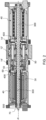
- the assembly of this disclosure allows the size of the motor to be maximised by providing a rod 30 through the actuator assembly, along the axis A' through the annulus of each of the earth members 14' and the output member 12' onto which the motor 40 is mounted.
- the rod 30 extends axially out from both ends of the actuator assembly defined by the earth members 14' and the output member 12' providing a motor mounting portion 300 each side of the actuator assembly so that the assembly can be provided with two motors 40, one motor on each motor mounting portion 300.
- This is, however, just one example, and an arrangement is also feasible, using this concept, with only a single motor. In other implementations, several motors could be attached either side of the actuator, with the number of motors being determined by the application of the assembly.
- the motor 40 is mounted around the rod 30 and is engaged with the rod for rotation of the rod with the motor e.g. via a mating spline arrangement 400 between the motor and the rod 30.
- a mating spline arrangement 400 between the motor and the rod 30.
- the motor 40 (or, here, each motor) is held in tight engagement with the rod by means of fasteners at the axially outer ends of the motor that apply an axially inward tension on the motor to secure it to the rod.
- fasteners 500 are provided at each end of the rod, but it is also feasible to have fasteners at only one end. As the motor 40 rotates, therefore, it causes rotation of the rod 30.
- the rod 30 is connected to rotatably drive the output member 12'.
- the rod may be directly connected to the output member 12' such that rotation of the rod causes a corresponding rotation of the output member.
- the rod may be connected to the output member by means of a gear assembly 50 arranged coaxially around the rod, between the rod and the output member 12'.
- a gear assembly 50 arranged coaxially around the rod, between the rod and the output member 12'.
- a locking mechanism such as an anti-rotation pin 60 may be provided between the earth members and the motor.
- the rod 30 can extend beyond the ends of the actuator assembly (see 70), it is also possible to rotate the rod manually to cause rotation of the output member.
Landscapes
- Engineering & Computer Science (AREA)
- Automation & Control Theory (AREA)
- Aviation & Aerospace Engineering (AREA)
- Power Engineering (AREA)
- Connection Of Motors, Electrical Generators, Mechanical Devices, And The Like (AREA)
Priority Applications (2)
| Application Number | Priority Date | Filing Date | Title |
|---|---|---|---|
| EP23275111.5A EP4497677A1 (de) | 2023-07-26 | 2023-07-26 | Drehaktuatoranordnung |
| US18/774,050 US20250033764A1 (en) | 2023-07-26 | 2024-07-16 | Rotary actuator assembly |
Applications Claiming Priority (1)
| Application Number | Priority Date | Filing Date | Title |
|---|---|---|---|
| EP23275111.5A EP4497677A1 (de) | 2023-07-26 | 2023-07-26 | Drehaktuatoranordnung |
Publications (1)
| Publication Number | Publication Date |
|---|---|
| EP4497677A1 true EP4497677A1 (de) | 2025-01-29 |
Family
ID=87517290
Family Applications (1)
| Application Number | Title | Priority Date | Filing Date |
|---|---|---|---|
| EP23275111.5A Pending EP4497677A1 (de) | 2023-07-26 | 2023-07-26 | Drehaktuatoranordnung |
Country Status (2)
| Country | Link |
|---|---|
| US (1) | US20250033764A1 (de) |
| EP (1) | EP4497677A1 (de) |
Citations (4)
| Publication number | Priority date | Publication date | Assignee | Title |
|---|---|---|---|---|
| DE69516987T2 (de) * | 1994-11-28 | 2000-11-30 | Aerospatiale Matra, Paris | Konischer Drehflügelantrieb und seine Verwendung zur Steuerung eines Scharniers eines Flugzeuges |
| US20030100398A1 (en) * | 2001-11-08 | 2003-05-29 | Mckay Richard John | Rotary actuator |
| US11273904B2 (en) * | 2019-01-02 | 2022-03-15 | Airbus Operations Limited | Actuator assembly for moving an aircraft wing tip device |
| EP4180324A1 (de) * | 2021-11-16 | 2023-05-17 | Goodrich Actuation Systems Limited | Befestigung für einen drehantrieb |
Family Cites Families (1)
| Publication number | Priority date | Publication date | Assignee | Title |
|---|---|---|---|---|
| FR2727477A1 (fr) * | 1994-11-28 | 1996-05-31 | Aerospatiale | Verin rotatif conique et son application a la commande d'une gouverne d'aeronef |
-
2023
- 2023-07-26 EP EP23275111.5A patent/EP4497677A1/de active Pending
-
2024
- 2024-07-16 US US18/774,050 patent/US20250033764A1/en active Pending
Patent Citations (4)
| Publication number | Priority date | Publication date | Assignee | Title |
|---|---|---|---|---|
| DE69516987T2 (de) * | 1994-11-28 | 2000-11-30 | Aerospatiale Matra, Paris | Konischer Drehflügelantrieb und seine Verwendung zur Steuerung eines Scharniers eines Flugzeuges |
| US20030100398A1 (en) * | 2001-11-08 | 2003-05-29 | Mckay Richard John | Rotary actuator |
| US11273904B2 (en) * | 2019-01-02 | 2022-03-15 | Airbus Operations Limited | Actuator assembly for moving an aircraft wing tip device |
| EP4180324A1 (de) * | 2021-11-16 | 2023-05-17 | Goodrich Actuation Systems Limited | Befestigung für einen drehantrieb |
Also Published As
| Publication number | Publication date |
|---|---|
| US20250033764A1 (en) | 2025-01-30 |
Similar Documents
| Publication | Publication Date | Title |
|---|---|---|
| US20230150652A1 (en) | Attachment for rotary actuator | |
| EP3029358B1 (de) | Leichter und nachgiebiger lagerzapfen | |
| US8966911B2 (en) | Turbofan engine with HP and LP power off-takes | |
| DE102012107419A1 (de) | Anstellwinkeländerungsmechanismus für offenliegenen Rotoraufbau | |
| EP4163475A1 (de) | Rotoranordnung für einen gasturbinenmotor und verfahren zur montage davon | |
| EP2587020B1 (de) | Lagerzapfen für Getriebesystem | |
| EP3957835B1 (de) | System für einen phaser mit variablem komprimierungsverhältnis | |
| US12313154B2 (en) | Strain wave drive | |
| EP4497677A1 (de) | Drehaktuatoranordnung | |
| US5106354A (en) | One-piece planetary gear for a rotary actuator and method of assembling a rotary actuator with a one-piece planetary gear | |
| EP4134571A1 (de) | Zusammengesetztes harmonisches getriebesystem mit zwei motorkurbeln | |
| US12448120B2 (en) | Shaft assembly for split torque gear box | |
| EP4542082A1 (de) | Lagerdeckel | |
| BR102024012731A2 (pt) | Conjunto do atuador rotativo, e, conjunto de montagem | |
| CN116250168A (zh) | 具有圆柱形壳体的齿轮马达及相应的管状马达 | |
| US20260092565A1 (en) | Gas Turbine Engine Tower Shaft Assembly | |
| US12146444B1 (en) | Gearbox assembly for an aircraft propulsion system | |
| US12104541B1 (en) | Method and system for assembling a reduction gearbox | |
| US10982545B2 (en) | Rotor coupling ring | |
| US20260092566A1 (en) | Gas Turbine Engine Tower Shaft with Narrowed Support Member | |
| EP3578781B1 (de) | Getriebe mit mehreren montageflächen | |
| BR102022023036A2 (pt) | Conjuntos de atuador rotativo, de montagem e de asa, e, método para fixar um conjunto de atuador rotativo |
Legal Events
| Date | Code | Title | Description |
|---|---|---|---|
| PUAI | Public reference made under article 153(3) epc to a published international application that has entered the european phase |
Free format text: ORIGINAL CODE: 0009012 |
|
| STAA | Information on the status of an ep patent application or granted ep patent |
Free format text: STATUS: THE APPLICATION HAS BEEN PUBLISHED |
|
| AK | Designated contracting states |
Kind code of ref document: A1 Designated state(s): AL AT BE BG CH CY CZ DE DK EE ES FI FR GB GR HR HU IE IS IT LI LT LU LV MC ME MK MT NL NO PL PT RO RS SE SI SK SM TR |
|
| STAA | Information on the status of an ep patent application or granted ep patent |
Free format text: STATUS: REQUEST FOR EXAMINATION WAS MADE |
|
| 17P | Request for examination filed |
Effective date: 20250729 |