EP4134571A1 - Zusammengesetztes harmonisches getriebesystem mit zwei motorkurbeln - Google Patents
Zusammengesetztes harmonisches getriebesystem mit zwei motorkurbeln Download PDFInfo
- Publication number
- EP4134571A1 EP4134571A1 EP22174184.6A EP22174184A EP4134571A1 EP 4134571 A1 EP4134571 A1 EP 4134571A1 EP 22174184 A EP22174184 A EP 22174184A EP 4134571 A1 EP4134571 A1 EP 4134571A1
- Authority
- EP
- European Patent Office
- Prior art keywords
- gear
- ground
- output
- drive shaft
- wave generator
- Prior art date
- Legal status (The legal status is an assumption and is not a legal conclusion. Google has not performed a legal analysis and makes no representation as to the accuracy of the status listed.)
- Pending
Links
Images




Classifications
-
- F—MECHANICAL ENGINEERING; LIGHTING; HEATING; WEAPONS; BLASTING
- F16—ENGINEERING ELEMENTS AND UNITS; GENERAL MEASURES FOR PRODUCING AND MAINTAINING EFFECTIVE FUNCTIONING OF MACHINES OR INSTALLATIONS; THERMAL INSULATION IN GENERAL
- F16H—GEARING
- F16H49/00—Other gearings
- F16H49/001—Wave gearings, e.g. harmonic drive transmissions
-
- B—PERFORMING OPERATIONS; TRANSPORTING
- B64—AIRCRAFT; AVIATION; COSMONAUTICS
- B64C—AEROPLANES; HELICOPTERS
- B64C13/00—Control systems or transmitting systems for actuating flying-control surfaces, lift-increasing flaps, air brakes, or spoilers
- B64C13/24—Transmitting means
- B64C13/26—Transmitting means without power amplification or where power amplification is irrelevant
- B64C13/28—Transmitting means without power amplification or where power amplification is irrelevant mechanical
- B64C13/34—Transmitting means without power amplification or where power amplification is irrelevant mechanical using toothed gearing
-
- B—PERFORMING OPERATIONS; TRANSPORTING
- B64—AIRCRAFT; AVIATION; COSMONAUTICS
- B64C—AEROPLANES; HELICOPTERS
- B64C13/00—Control systems or transmitting systems for actuating flying-control surfaces, lift-increasing flaps, air brakes, or spoilers
- B64C13/24—Transmitting means
- B64C13/26—Transmitting means without power amplification or where power amplification is irrelevant
- B64C13/28—Transmitting means without power amplification or where power amplification is irrelevant mechanical
-
- F—MECHANICAL ENGINEERING; LIGHTING; HEATING; WEAPONS; BLASTING
- F16—ENGINEERING ELEMENTS AND UNITS; GENERAL MEASURES FOR PRODUCING AND MAINTAINING EFFECTIVE FUNCTIONING OF MACHINES OR INSTALLATIONS; THERMAL INSULATION IN GENERAL
- F16H—GEARING
- F16H49/00—Other gearings
- F16H49/001—Wave gearings, e.g. harmonic drive transmissions
- F16H2049/003—Features of the flexsplines therefor
Definitions
- Exemplary embodiments pertain to the art of gear systems and more specifically to a compound harmonic gear system with dual output arms.
- Compound harmonic gear systems are configured to provide hinge-line compound harmonics and may achieve higher power density compared with other gear systems.
- compound harmonic gear systems designed with a single output arm can lead to an unbalanced load and large reactive forces in the arm.
- a gear system including: first and second ground gear; a drive shaft disposed along a rotation axis of the gear system and configured to rotate about the rotation axis; and an output gear supported by the first and second ground gear and configured to rotate by engagement between a wave generator portion of a drive shaft, a wave generator bearing, a flex spline, the output gear and the first and second ground gear, the output gear defining: an output gear body; and first and second output arms respectively extending radially outward from opposite sides of the output gear body to respectively define first and second radial inner ends and radial outer ends of the first and second output arms, so that the first and second radial outer ends are disposed on a radial axis that extends through a radial center of the gear system.
- the output gear body defines an output gear aperture boundary, which defines an output gear aperture through which the wave generator portion of the drive shaft, the wave generator bearing and the flex spline extend.
- the first ground gear defines a first ground gear body that is ring shaped; the first ground gear body defines a first ground gear aperture boundary, which defines a first ground gear aperture through which the wave generator portion of the drive shaft, the wave generator bearing and the flex spline extend.
- the first ground gear is disposed on a first side of the output gear along the rotation axis; the second ground gear on a second side of the output gear along the rotation axis, wherein the first and second ground gears are connected to each other with the output gear therebetween along the rotation axis; and the second ground gear is a same shape as the first ground gear such that the second ground gear defines: a second ground gear body with a second ground gear aperture boundary that defines a second ground gear aperture.
- the wave generator portion of the drive shaft is defined at a first axial end of the drive shaft, and aligned along the rotation axis with the first and second ground gear apertures; and an input shaft portion of the drive shaft is defined at a second axial end of the drive shaft, wherein the input shaft portion is cylindrical, and the first and second axial ends are adjacent along the rotation axis.
- the wave generator bearing disposed radially around the wave generator portion of the drive shaft, and aligned along the rotation axis with the first and second ground gear apertures.
- the flex spline is located between the wave generator bearing and the first and second ground gear aperture boundaries, and aligned along the rotation axis with the first and second ground gear apertures, and wherein, during rotation of the input shaft portion of the drive shaft: the flex spline is engaged by the wave generator portion of the drive shaft; and the output gear is driven to rotate from engagement of the flex spline with the output gear and the first and second ground gear.
- the first ground gear includes a first set of mount segments, including first and second mount segments, that extend along the rotation axis from the first ground gear body, and are circumferentially spaced apart from each other about the first ground gear body to define rotation limiters for the first and second output arms.
- first and second output arms are shaped to respectively taper from the first and second radial inner ends to the first and second radial outer ends; and the first and second inner ends alternatively engage the first and second mount segments during rotation of the output gear to thereby limit motion of the output gear.
- the second ground gear defines a second set of mount segments, including third and fourth mount segments, that extend along the rotation axis from the second ground gear body; and the first mount segment is fixed to the third mount segment, and the second mount segment is fixed to the fourth mount segment, whereby the first and second ground gears are connected to each other.
- the wave generator portion of the drive shaft, the wave generator bearing, and the flex spline extend through the first ground gear aperture, the output gear aperture and the second ground gear aperture and have a same length along the rotation axis.
- the mount segments define ground gear mounting features; and the output arms define output arm mounting features, whereby the gear system is configured to mount to a movable component to a stationary structure.
- an aircraft system including: a stationary structure; and a movable component mounted to the stationary structure via a gear system having one or more of the above disclosed aspects.
- the movable component is a control surface.
- the aircraft system includes a motor operationally connected to the drive shaft.
- a method of transmitting rotational motion to a movable component via a gear system including: connecting a stationary structure to first and second ground gear of the gear system, wherein the gear system includes: a drive shaft disposed along a rotation axis of the gear system; and an output gear supported by the first and second ground gear and configured to rotate by engagement between a wave generator portion of the drive shaft, a wave generator bearing, a flex spline, the first and second ground gear and the output gear, the output gear defining: an output gear body; and first and second output arms respectively extending radially outward from circumferentially opposite portions of the output gear body to respectively define first and second radial inner ends and radial outer ends of the first and second output arms, so that the first and second radial outer ends are disposed on a radial axis that extends through a radial center of the gear system; connecting the movable component to the first and second output arms of the output gear of the gear system; and rotating the drive shaft disposed along the rotation
- the method includes connecting a motor to an input shaft portion of the drive shaft prior to rotating the drive shaft and rotating the drive shaft with the motor.
- FIG. 1 illustrates an example of a commercial aircraft 10 having an aircraft engine 20 surrounded by (or otherwise carried in) a nacelle.
- the commercial aircraft 10 includes two wings 22 that can each include one or more slats 24 and one or more flaps 26.
- the aircraft may further include ailerons 27, spoilers 28, horizontal stabilizer trim tabs 29, horizontal stabilizer 30 and rudder 31, and vertical stabilizer 32 (the tail structure being collectively referred to as an and empennage) each of which may be typically referred to as "control surfaces" as they are movable under aircraft power systems.
- compound harmonic gear systems can be useful to control motion of aircraft components such as the control surfaces identified above.
- these systems may have unbalanced loads and large reactive forces if they are designed with a single output arm. These loads may result in a binding of the gears and may require a relatively robust structure to prevent material failure.
- the gear system 100 can receive power via a drive shaft 120 and transfer the power to an output gear 140, e.g., to drive a control surface of an aircraft.
- the gear system 100 includes first and second ground gears 110A, 110B (generally referenced as 110).
- a drive shaft 120 is disposed along a rotation axis 130 of the gear system 100 and is configured to rotate about the rotation axis 130.
- An output gear 140 is supported by the first and second ground gear 110A, 110B and configured to rotate by engagement with the drive shaft 120 via a wave generator bearing 142 and a flex spline 144, as discussed in greater detail below.
- the output gear 140 is shown, along with the wave generator bearing 142, the flex spline 144 and portions of the second ground gear 110B, all disposed along the rotation axis 130.
- the output gear 140 defines an output gear body 150.
- First and second output arms 160A, 160B (generally referenced as 160) extend radially outward from opposite sides of the output gear body 150, e.g., from first and second portions 170A, 170B (generally referenced as 170) of the output gear body 150.
- the output arms 160 respectively define first and second radial inner ends 180A, 180B (generally referenced as 180) and radial outer ends 190A, 190B (generally referenced as 190).
- the radial outer ends 190 are disposed on a radial axis 200 that extends through a radial center 210 of the gear system 100.
- the output gear body 150 defines an output gear aperture boundary 220, which defines an output gear aperture 230 through which the drive shaft 120 extends ( FIG. 2 ).
- the output arms 160 are shaped to respectively taper from the radial inner ends 180 to the radial outer ends 190.
- the shape of the output arms 160 is substantially an isosceles trapezoid with rounded corner edges, with the radial outer ends 190 being the small base of the trapezoid and the radial inner ends 180 being the large base of the trapezoid.
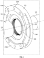
- the first ground gear 110A is shown along with portions of the drive shaft 120 and the wave generator bearing 142, all disposed along the rotation axis 130.
- the first ground gear 110A defines a first ground gear body 240 that is ring shaped.
- the first ground gear body 240 defines a first ground gear aperture boundary 250, which defines a first ground gear aperture 260 through which the drive shaft 120 extends.
- the first ground gear 110A includes first and second mount segments 270A, 270B (generally referenced as first set of mount segments 270).
- the first set of mount segments 270 extend along the rotation axis 130 from the first ground gear body 240, toward the output gear 140 ( FIG. 2 ).
- the first set of mount segments 270 are circumferentially spaced apart (along the circumferential direction 165) from each other about the first ground gear body 240.
- the first set of mount segments 270 define rotation limiters (or stops) for the output arms 160. That is, as the output arms 160 move circumferentially during rotation, the radial inner ends 180 of the output arms 160 ( FIG. 4 ) will abut circumferential ends of the first set of mount segments 270 to prevent continuing rotation in a direction of rotational motion, to thereby limit motion of the output gear ( FIG. 7 ).
- the drive shaft 120 is shown along the rotation axis 130.
- the drive shaft 120 defines a wave generator portion 280 at a first axial end 290 of the drive shaft 120, aligned along the rotation axis 130 with the first ground gear aperture 260 ( FIG. 4 ).
- An input shaft portion 300 is at a second axial end 310 of the drive shaft 120.
- the input shaft portion 300 is cylindrical in shape.
- the first and second axial ends 290, 310 are adjacent to each other along the rotation axis 130.
- the input shaft portion 300 is driven by a motor 400 (discussed below).
- the first ground gear 110A is disposed on a first side of the output gear 140 along the rotation axis 130.
- the second ground gear 110B is located on a second side of the output gear 140 along the rotation axis 130.
- the ground gears 110 are connected to each other with the output gear 140 therebetween along the rotation axis 130.
- FIG. 6 the second ground gear 110B is shown along the rotation axis 130.
- the second ground gear 110B is a same shape and size as the first ground gear 110A.
- the second ground gear 110B defines a second ground gear body 320 with a second ground gear aperture boundary 330 that defines a second ground gear aperture 340.
- Third and fourth mount segments 350A, 350B (generally referred to as a second set of mount segments 350) extend along the rotation axis 130 from the second ground gear body 320, toward the output gear 140.
- the wave generator bearing 142 is radially exterior to the wave generator portion 280 of the drive shaft 120 and is aligned along the rotation axis 130 with the first ground gear aperture 260 (see also FIG. 7 ).
- the flex spline 144 is radially between the wave generator bearing 142 and the first and second ground gear aperture boundaries 250, 330 and is aligned along the rotation axis 130 with the first and second ground gear apertures 260, 340 (see also FIG. 7 ).
- FIG. 7 which is an assembly view of the gear system 100
- the first and second set of mount segments 270, 350 are fixed to each other. From this, the first and second ground gears 110A, 110B are connected to each other.
- the wave generator portion 280 of the drive shaft 120, the wave generator bearing 142, and the flex spline 144 extend through the first ground gear aperture 260 ( FIG. 4 ), the output gear aperture 230 ( FIG. 3 ) and the second ground gear aperture 330.
- the wave generator portion 280 of the drive shaft 120 ( FIG. 2 ), the wave generator bearing 142, and the flex spline 144 have a same length along the rotation axis 130.
- the first and second sets of mount segments 270, 350 have ground gear mounting features 360 such as through-holes.
- the output arms 160 define output arm mounting features 370, which may also be through-holes.
- the gear system 100 is configured to mount to a movable component 380 and to a stationary structure 390.
- the stationary structure 390 may be, for example, within an aircraft 10 ( FIG. 1 ) and the movable component 380 may be a control surface such as a flap or slat.
- a motor 400 may be operationally connected to the drive shaft 120 to enable rotation of the movable component 380 via the gear system 100.
- FIG. 9 generally shows the drive shaft 120, the ground gear 110, the output gear 140, the wave generator bearing 142, and the flex spline 144.
- the flex spline 144 includes a plurality of splines 420 (e.g., FIG. 4 ) to thereby form a compound spline.
- the flex spline 144 includes a first ground spline 420A, a second ground spline 420B and an output spline 420C.
- the second ground spline 420B is axially offset from the first ground spline 420A.
- the output spline 420C is axially intermediate the first ground spline 420A and the second ground spline 420B.
- Each of the first ground spline 420A, the second ground spline 420B and the output spline 420C are outer facing splines.
- the first ground gear 110A includes first ground gear teeth 430A.
- the first ground gear teeth 430A mesh with the first ground spline 420A.
- the second ground gear 110B includes second ground gear teeth 430B.
- the second ground gear teeth 430B mesh with the second ground spline 420B.
- the output gear 140 includes output gear teeth 430C.
- the output gear teeth 430C mesh with the output spline 420C.
- Each of the first ground gear teeth 430A, the second ground gear teeth 430B and the output gear teeth 430C are inner facing teeth.
- the plurality of splines 420 are configured to mesh with the ground gears 110 and the output flange 140 according to different gear ratios.
- the first ground spline 420A and the first ground gear teeth 430A have a first gear ratio (Ratio 1, below).
- the second ground spline 420B and the second ground gear teeth 430B also have the first gear ratio.
- the output spline 420C and the output gear teeth 430C have a second gear ratio (Ratio 2, below) that differs from the first gear ratio.
- the splines 420 are integral to same structure, that is, the flex spline 144.
- the different gear ratios together form a compound gear ratio (Compound Ratio, below).
- the compound gear ratio provides a differential motion between the ground gears 110 and the output gear 140.
- Ratio 1 Teeth in Output Spline 420 c Teeth in Output Spline 420 c ⁇ Teeth in Outpt Flange 430
- FIG. 10 is a flowchart showing a method of transmitting rotational motion to a movable component 380.
- the method includes connecting the first and second ground gear 110A, 110B of the gear system 100 to a stationary structure 390.
- the method includes connecting the movable component to the first and second output arms 160A, 160B, of the output gear 140 of the gear system 100.
- the method includes rotating the drive shaft 120 disposed along the rotation axis of the gear system 100, and rotationally driving the output gear 140 from rotation of the drive shaft 120.
- a wave generator portion 280 of the drive shaft 120 engages a wave generator bearing 142 and a flex spline 144, and thereby engages the output gear 140 and the ground gear 110A, 110B, to drive the output gear 140.
- the method may include connecting the motor 400 to the input shaft portion 300 of the drive shaft 120 prior to rotating the drive shaft 120, and thereafter rotating the drive shaft 120 with the motor 400.
- the embodiments disclosed herein provide dual output arms to provide a balanced load in compound harmonic gear system.
- dual output arms provide an additional structure to react loads, reducing the reactive forces in each arm compared with a single arm design.
- the lower reactive forces translate into lower deflections and can reduce the binding of the gear.
- less structure is required, which leads to mass and weight reduction.
Landscapes
- Engineering & Computer Science (AREA)
- Mechanical Engineering (AREA)
- General Engineering & Computer Science (AREA)
- Automation & Control Theory (AREA)
- Aviation & Aerospace Engineering (AREA)
- Retarders (AREA)
Applications Claiming Priority (1)
| Application Number | Priority Date | Filing Date | Title |
|---|---|---|---|
| US17/399,289 US12140213B2 (en) | 2021-08-11 | 2021-08-11 | Compound harmonic gear system with dual output arms |
Publications (1)
| Publication Number | Publication Date |
|---|---|
| EP4134571A1 true EP4134571A1 (de) | 2023-02-15 |
Family
ID=81748541
Family Applications (1)
| Application Number | Title | Priority Date | Filing Date |
|---|---|---|---|
| EP22174184.6A Pending EP4134571A1 (de) | 2021-08-11 | 2022-05-18 | Zusammengesetztes harmonisches getriebesystem mit zwei motorkurbeln |
Country Status (4)
| Country | Link |
|---|---|
| US (1) | US12140213B2 (de) |
| EP (1) | EP4134571A1 (de) |
| BR (1) | BR102022011362A2 (de) |
| CA (1) | CA3160866A1 (de) |
Families Citing this family (1)
| Publication number | Priority date | Publication date | Assignee | Title |
|---|---|---|---|---|
| US12215769B2 (en) | 2023-02-13 | 2025-02-04 | Hamilton Sundstrand Corporation | Harmonic drive with flex spline end clamps |
Citations (2)
| Publication number | Priority date | Publication date | Assignee | Title |
|---|---|---|---|---|
| EP3561337A1 (de) * | 2018-04-24 | 2019-10-30 | Hamilton Sundstrand Corporation | Magnetisch angetriebenes gleitkeilgetriebe |
| EP3726096A1 (de) * | 2019-04-18 | 2020-10-21 | Hamilton Sundstrand Corporation | Invertiertes verbundwellgetriebe |
Family Cites Families (4)
| Publication number | Priority date | Publication date | Assignee | Title |
|---|---|---|---|---|
| US9915334B2 (en) * | 2015-10-16 | 2018-03-13 | Hamilton Sundstrand Corporation | Flex spline for use with a compound harmonic generator |
| US10266251B2 (en) * | 2016-01-12 | 2019-04-23 | Hamilton Sundstrand Corporation | Position sensor for electromechanical actuator |
| US10400878B2 (en) | 2016-10-20 | 2019-09-03 | Hamilton Sundstrand Corporation | Compound harmonic drive assembly |
| US10883590B2 (en) | 2017-07-07 | 2021-01-05 | Hamilton Sunstrand Corporation | Compound harmonic gear |
-
2021
- 2021-08-11 US US17/399,289 patent/US12140213B2/en active Active
-
2022
- 2022-05-18 EP EP22174184.6A patent/EP4134571A1/de active Pending
- 2022-05-27 CA CA3160866A patent/CA3160866A1/en active Pending
- 2022-06-09 BR BR102022011362-9A patent/BR102022011362A2/pt active IP Right Grant
Patent Citations (2)
| Publication number | Priority date | Publication date | Assignee | Title |
|---|---|---|---|---|
| EP3561337A1 (de) * | 2018-04-24 | 2019-10-30 | Hamilton Sundstrand Corporation | Magnetisch angetriebenes gleitkeilgetriebe |
| EP3726096A1 (de) * | 2019-04-18 | 2020-10-21 | Hamilton Sundstrand Corporation | Invertiertes verbundwellgetriebe |
Also Published As
| Publication number | Publication date |
|---|---|
| CA3160866A1 (en) | 2023-02-11 |
| US20230048660A1 (en) | 2023-02-16 |
| US12140213B2 (en) | 2024-11-12 |
| BR102022011362A2 (pt) | 2023-02-14 |
Similar Documents
| Publication | Publication Date | Title |
|---|---|---|
| DE69332507T2 (de) | Rotorblattanordnung für unbemanntes Fluggerät | |
| EP3279512B1 (de) | Verbundene flexspline für zusammengesetztes gleitkeilgetriebe | |
| US20230105006A1 (en) | Hinge-line actuator for rotating an aircraft control surface | |
| CN109923335B (zh) | 用于具有行星齿轮系的减速单元的行星架 | |
| US3902822A (en) | Modular gearbox for a variable pitch fan propulsor | |
| EP3098477A2 (de) | Planetengetriebesystem und planetenträger | |
| US20230150652A1 (en) | Attachment for rotary actuator | |
| EP4134571A1 (de) | Zusammengesetztes harmonisches getriebesystem mit zwei motorkurbeln | |
| US2245251A (en) | Articulated propeller | |
| EP3726096B1 (de) | Invertiertes verbundwellgetriebe | |
| EP3193040A1 (de) | Planetengetriebeanordnung | |
| US12313154B2 (en) | Strain wave drive | |
| US10724625B2 (en) | Torsionally compliant geartrain carrier assembly | |
| EP3137377B1 (de) | Radial elastische hohlwelle | |
| EP4283164B1 (de) | Harmonic drive getriebe mit geteilter flexspline | |
| US11186381B2 (en) | Integral multistage ring gear systems for aircraft | |
| US11391356B2 (en) | Hybrid gear construction | |
| US8240601B2 (en) | Coupling with slack-takeup, a rotor, and a rotary wing aircraft | |
| US12448120B2 (en) | Shaft assembly for split torque gear box | |
| RU2824002C1 (ru) | Главный редуктор соосной схемы привода несущих винтов легкого или сверхлегкого вертолета | |
| KR102457195B1 (ko) | 무인항공기용 싱글 프로펠러 조립체 | |
| RU2729900C9 (ru) | Система привода соосных несущих винтов вертолёта с опорной мачтой | |
| US11225324B2 (en) | Dual flex-beam assembly for folding rotor blade | |
| US2001189A (en) | Controllable pitch propeller | |
| WO1992006317A1 (en) | Offset face gear transmission |
Legal Events
| Date | Code | Title | Description |
|---|---|---|---|
| PUAI | Public reference made under article 153(3) epc to a published international application that has entered the european phase |
Free format text: ORIGINAL CODE: 0009012 |
|
| STAA | Information on the status of an ep patent application or granted ep patent |
Free format text: STATUS: THE APPLICATION HAS BEEN PUBLISHED |
|
| AK | Designated contracting states |
Kind code of ref document: A1 Designated state(s): AL AT BE BG CH CY CZ DE DK EE ES FI FR GB GR HR HU IE IS IT LI LT LU LV MC MK MT NL NO PL PT RO RS SE SI SK SM TR |
|
| STAA | Information on the status of an ep patent application or granted ep patent |
Free format text: STATUS: REQUEST FOR EXAMINATION WAS MADE |
|
| 17P | Request for examination filed |
Effective date: 20230809 |
|
| RBV | Designated contracting states (corrected) |
Designated state(s): AL AT BE BG CH CY CZ DE DK EE ES FI FR GB GR HR HU IE IS IT LI LT LU LV MC MK MT NL NO PL PT RO RS SE SI SK SM TR |
|
| STAA | Information on the status of an ep patent application or granted ep patent |
Free format text: STATUS: EXAMINATION IS IN PROGRESS |
|
| 17Q | First examination report despatched |
Effective date: 20241111 |