EP4497604A1 - Druckvorrichtung - Google Patents
Druckvorrichtung Download PDFInfo
- Publication number
- EP4497604A1 EP4497604A1 EP24190832.6A EP24190832A EP4497604A1 EP 4497604 A1 EP4497604 A1 EP 4497604A1 EP 24190832 A EP24190832 A EP 24190832A EP 4497604 A1 EP4497604 A1 EP 4497604A1
- Authority
- EP
- European Patent Office
- Prior art keywords
- ink
- tank
- ink tank
- printing apparatus
- storage chamber
- Prior art date
- Legal status (The legal status is an assumption and is not a legal conclusion. Google has not performed a legal analysis and makes no representation as to the accuracy of the status listed.)
- Pending
Links
Images







Classifications
-
- B—PERFORMING OPERATIONS; TRANSPORTING
- B41—PRINTING; LINING MACHINES; TYPEWRITERS; STAMPS
- B41J—TYPEWRITERS; SELECTIVE PRINTING MECHANISMS, i.e. MECHANISMS PRINTING OTHERWISE THAN FROM A FORME; CORRECTION OF TYPOGRAPHICAL ERRORS
- B41J2/00—Typewriters or selective printing mechanisms characterised by the printing or marking process for which they are designed
- B41J2/005—Typewriters or selective printing mechanisms characterised by the printing or marking process for which they are designed characterised by bringing liquid or particles selectively into contact with a printing material
- B41J2/01—Ink jet
- B41J2/17—Ink jet characterised by ink handling
- B41J2/175—Ink supply systems ; Circuit parts therefor
- B41J2/17503—Ink cartridges
- B41J2/17513—Inner structure
-
- B—PERFORMING OPERATIONS; TRANSPORTING
- B41—PRINTING; LINING MACHINES; TYPEWRITERS; STAMPS
- B41J—TYPEWRITERS; SELECTIVE PRINTING MECHANISMS, i.e. MECHANISMS PRINTING OTHERWISE THAN FROM A FORME; CORRECTION OF TYPOGRAPHICAL ERRORS
- B41J2/00—Typewriters or selective printing mechanisms characterised by the printing or marking process for which they are designed
- B41J2/005—Typewriters or selective printing mechanisms characterised by the printing or marking process for which they are designed characterised by bringing liquid or particles selectively into contact with a printing material
- B41J2/01—Ink jet
- B41J2/17—Ink jet characterised by ink handling
- B41J2/175—Ink supply systems ; Circuit parts therefor
- B41J2/17503—Ink cartridges
-
- B—PERFORMING OPERATIONS; TRANSPORTING
- B41—PRINTING; LINING MACHINES; TYPEWRITERS; STAMPS
- B41J—TYPEWRITERS; SELECTIVE PRINTING MECHANISMS, i.e. MECHANISMS PRINTING OTHERWISE THAN FROM A FORME; CORRECTION OF TYPOGRAPHICAL ERRORS
- B41J2/00—Typewriters or selective printing mechanisms characterised by the printing or marking process for which they are designed
- B41J2/005—Typewriters or selective printing mechanisms characterised by the printing or marking process for which they are designed characterised by bringing liquid or particles selectively into contact with a printing material
- B41J2/01—Ink jet
- B41J2/17—Ink jet characterised by ink handling
- B41J2/175—Ink supply systems ; Circuit parts therefor
- B41J2/17503—Ink cartridges
- B41J2/1752—Mounting within the printer
- B41J2/17523—Ink connection
-
- B—PERFORMING OPERATIONS; TRANSPORTING
- B41—PRINTING; LINING MACHINES; TYPEWRITERS; STAMPS
- B41J—TYPEWRITERS; SELECTIVE PRINTING MECHANISMS, i.e. MECHANISMS PRINTING OTHERWISE THAN FROM A FORME; CORRECTION OF TYPOGRAPHICAL ERRORS
- B41J11/00—Devices or arrangements of selective printing mechanisms, e.g. ink-jet printers or thermal printers, for supporting or handling copy material in sheet or web form
- B41J11/0045—Guides for printing material
-
- B—PERFORMING OPERATIONS; TRANSPORTING
- B41—PRINTING; LINING MACHINES; TYPEWRITERS; STAMPS
- B41J—TYPEWRITERS; SELECTIVE PRINTING MECHANISMS, i.e. MECHANISMS PRINTING OTHERWISE THAN FROM A FORME; CORRECTION OF TYPOGRAPHICAL ERRORS
- B41J2/00—Typewriters or selective printing mechanisms characterised by the printing or marking process for which they are designed
- B41J2/005—Typewriters or selective printing mechanisms characterised by the printing or marking process for which they are designed characterised by bringing liquid or particles selectively into contact with a printing material
- B41J2/01—Ink jet
- B41J2/17—Ink jet characterised by ink handling
- B41J2/175—Ink supply systems ; Circuit parts therefor
- B41J2/17503—Ink cartridges
- B41J2/17506—Refilling of the cartridge
-
- B—PERFORMING OPERATIONS; TRANSPORTING
- B41—PRINTING; LINING MACHINES; TYPEWRITERS; STAMPS
- B41J—TYPEWRITERS; SELECTIVE PRINTING MECHANISMS, i.e. MECHANISMS PRINTING OTHERWISE THAN FROM A FORME; CORRECTION OF TYPOGRAPHICAL ERRORS
- B41J2/00—Typewriters or selective printing mechanisms characterised by the printing or marking process for which they are designed
- B41J2/005—Typewriters or selective printing mechanisms characterised by the printing or marking process for which they are designed characterised by bringing liquid or particles selectively into contact with a printing material
- B41J2/01—Ink jet
- B41J2/17—Ink jet characterised by ink handling
- B41J2/175—Ink supply systems ; Circuit parts therefor
- B41J2/17503—Ink cartridges
- B41J2/1752—Mounting within the printer
-
- B—PERFORMING OPERATIONS; TRANSPORTING
- B41—PRINTING; LINING MACHINES; TYPEWRITERS; STAMPS
- B41J—TYPEWRITERS; SELECTIVE PRINTING MECHANISMS, i.e. MECHANISMS PRINTING OTHERWISE THAN FROM A FORME; CORRECTION OF TYPOGRAPHICAL ERRORS
- B41J2/00—Typewriters or selective printing mechanisms characterised by the printing or marking process for which they are designed
- B41J2/005—Typewriters or selective printing mechanisms characterised by the printing or marking process for which they are designed characterised by bringing liquid or particles selectively into contact with a printing material
- B41J2/01—Ink jet
- B41J2/17—Ink jet characterised by ink handling
- B41J2/175—Ink supply systems ; Circuit parts therefor
- B41J2/17503—Ink cartridges
- B41J2/17526—Electrical contacts to the cartridge
- B41J2/1753—Details of contacts on the cartridge, e.g. protection of contacts
-
- B—PERFORMING OPERATIONS; TRANSPORTING
- B41—PRINTING; LINING MACHINES; TYPEWRITERS; STAMPS
- B41J—TYPEWRITERS; SELECTIVE PRINTING MECHANISMS, i.e. MECHANISMS PRINTING OTHERWISE THAN FROM A FORME; CORRECTION OF TYPOGRAPHICAL ERRORS
- B41J2/00—Typewriters or selective printing mechanisms characterised by the printing or marking process for which they are designed
- B41J2/005—Typewriters or selective printing mechanisms characterised by the printing or marking process for which they are designed characterised by bringing liquid or particles selectively into contact with a printing material
- B41J2/01—Ink jet
- B41J2/17—Ink jet characterised by ink handling
- B41J2/175—Ink supply systems ; Circuit parts therefor
- B41J2/17503—Ink cartridges
- B41J2/17553—Outer structure
-
- B—PERFORMING OPERATIONS; TRANSPORTING
- B41—PRINTING; LINING MACHINES; TYPEWRITERS; STAMPS
- B41J—TYPEWRITERS; SELECTIVE PRINTING MECHANISMS, i.e. MECHANISMS PRINTING OTHERWISE THAN FROM A FORME; CORRECTION OF TYPOGRAPHICAL ERRORS
- B41J2/00—Typewriters or selective printing mechanisms characterised by the printing or marking process for which they are designed
- B41J2/005—Typewriters or selective printing mechanisms characterised by the printing or marking process for which they are designed characterised by bringing liquid or particles selectively into contact with a printing material
- B41J2/01—Ink jet
- B41J2/17—Ink jet characterised by ink handling
- B41J2/175—Ink supply systems ; Circuit parts therefor
- B41J2/17503—Ink cartridges
- B41J2/17556—Means for regulating the pressure in the cartridge
-
- B—PERFORMING OPERATIONS; TRANSPORTING
- B41—PRINTING; LINING MACHINES; TYPEWRITERS; STAMPS
- B41J—TYPEWRITERS; SELECTIVE PRINTING MECHANISMS, i.e. MECHANISMS PRINTING OTHERWISE THAN FROM A FORME; CORRECTION OF TYPOGRAPHICAL ERRORS
- B41J2/00—Typewriters or selective printing mechanisms characterised by the printing or marking process for which they are designed
- B41J2/005—Typewriters or selective printing mechanisms characterised by the printing or marking process for which they are designed characterised by bringing liquid or particles selectively into contact with a printing material
- B41J2/01—Ink jet
- B41J2/17—Ink jet characterised by ink handling
- B41J2/175—Ink supply systems ; Circuit parts therefor
- B41J2/17566—Ink level or ink residue control
-
- B—PERFORMING OPERATIONS; TRANSPORTING
- B41—PRINTING; LINING MACHINES; TYPEWRITERS; STAMPS
- B41J—TYPEWRITERS; SELECTIVE PRINTING MECHANISMS, i.e. MECHANISMS PRINTING OTHERWISE THAN FROM A FORME; CORRECTION OF TYPOGRAPHICAL ERRORS
- B41J2/00—Typewriters or selective printing mechanisms characterised by the printing or marking process for which they are designed
- B41J2/005—Typewriters or selective printing mechanisms characterised by the printing or marking process for which they are designed characterised by bringing liquid or particles selectively into contact with a printing material
- B41J2/01—Ink jet
- B41J2/21—Ink jet for multi-colour printing
-
- B—PERFORMING OPERATIONS; TRANSPORTING
- B41—PRINTING; LINING MACHINES; TYPEWRITERS; STAMPS
- B41J—TYPEWRITERS; SELECTIVE PRINTING MECHANISMS, i.e. MECHANISMS PRINTING OTHERWISE THAN FROM A FORME; CORRECTION OF TYPOGRAPHICAL ERRORS
- B41J29/00—Details of, or accessories for, typewriters or selective printing mechanisms not otherwise provided for
- B41J29/02—Framework
-
- B—PERFORMING OPERATIONS; TRANSPORTING
- B41—PRINTING; LINING MACHINES; TYPEWRITERS; STAMPS
- B41J—TYPEWRITERS; SELECTIVE PRINTING MECHANISMS, i.e. MECHANISMS PRINTING OTHERWISE THAN FROM A FORME; CORRECTION OF TYPOGRAPHICAL ERRORS
- B41J2/00—Typewriters or selective printing mechanisms characterised by the printing or marking process for which they are designed
- B41J2/005—Typewriters or selective printing mechanisms characterised by the printing or marking process for which they are designed characterised by bringing liquid or particles selectively into contact with a printing material
- B41J2/01—Ink jet
- B41J2/17—Ink jet characterised by ink handling
- B41J2/175—Ink supply systems ; Circuit parts therefor
- B41J2/17566—Ink level or ink residue control
- B41J2002/17579—Measuring electrical impedance for ink level indication
Definitions
- the present invention relates to a printing apparatus equipped with a tank for storing a liquid such as ink.
- Ink tanks that store ink to be supplied to a print head that ejects ink are installed in inkjet printing apparatuses.
- ink tanks that are independent of one another for each of usable ink colors are installed side by side in the width direction.
- Japanese Patent Laid-Open No. 2018-069696 discloses a technology in which the width of a specific ink tank is widened compared to other ink tanks among multiple ink tanks in order to increase the amount of ink that can be stored in that specific ink tank.
- the minimum width of an ink tank is decided according to the length of the injection port for injecting ink in the width direction. Therefore, in a case where the width of the other ink tanks is the minimum width and it is desired to increase the storage capacity of a specific ink tank and widen the width thereof for that purpose, the width of the other ink tanks cannot be narrowed by the amount the width of the specific ink tank was widened. Therefore, in an inkjet printing apparatus, a large space is required to accommodate these ink tanks, which may result in an increase in the size of the apparatus.
- the present invention was made in view of the above issues, and provides a technology capable of suppressing the expansion of the space where the tanks that store the printing agents are accommodated.
- the present invention in its first aspect provides a printing apparatus as specified in claims 1 to 15.
- the printing apparatus may be an apparatus equipped only with the function of printing an image by ejecting ink onto a print medium, or the printing apparatus may be a multifunction peripheral equipped with the function of reading images and the like.
- an explanation is given as an example of a printing apparatus capable of color printing by ejecting ink of multiple colors. Therefore, in the present embodiment, as an example of the tanks, an explanation is given of ink tanks that store ink as liquid.
- the liquid that can be stored in the tanks is not limited to ink, which serves as a printing agent, but includes the various known printing agents used for printing, such as a treatment liquid that performs a specified treatment on the ejected ink.
- the various liquids used in a variety of known apparatuses that eject liquids to obtain a desired end product are included.
- the direction going from the left side towards the right side of the apparatus is explained as the X direction
- the direction going from the rear side (the back side) towards the near side (the front side) is explained as the Y direction
- the direction going from the lower side towards the upper side is explained as the Z direction.
- the X, Y, and Z directions are directions going from one side to the other side, and are directions orthogonal to one other.
- each direction is represented with a "+ (plus)" in a case of going from the one side to the other side, and with a "- (minus)” in a case of going from the other side to the one side, as appropriate.
- Fig. 1 is a schematic configuration diagram of the printing apparatus equipped with the liquid storage tanks according to the present embodiment.
- the printing apparatus 10 is equipped with the conveyance portion 12 that conveys the print medium fed from a feeding portion not illustrated in the drawings in the Y direction, and the printing portion 14 that ejects ink and performs printing onto the print medium conveyed by the conveyance portion 12. Note that the print medium on which printing has been performed by the printing portion 14 is discharged outside the apparatus at the front of the apparatus by a discharging portion (not illustrated in the drawings). Further, the printing apparatus 10 is also equipped with the accommodation portion 11 that accommodates the tanks (described later) that store the inks used in printing by the printing portion 14. Furthermore, the printing apparatus 10 is equipped with the control portion 200 (see Fig. 2 ) that controls the overall operation.
- the conveyance portion 12 is equipped with the conveyance roller 16, which is driven by a driving portion (not illustrated in the drawings), and the pinch roller 18 that makes pressure contact with the conveyance roller 16 and is associatively driven by the conveyance roller 16.
- the print medium fed by the feeding portion is nipped by the conveyance roller 16 and the pinch roller 18, and conveyed to the printing portion 14 by the rotation of the conveyance roller 16.
- the conveyance roller 16 is a metal roller that has been processed to have fine asperities on the surface with which the pinch roller 18 makes pressure contact, so that a frictional force is generated between the print medium and the roller as the roller nips the print medium with the pinch roller 18.
- the pinch roller 18 is elastically biased against the conveyance roller 16 by a biasing member such as a spring.
- the printing portion 14 is equipped with the print head 20 that ejects ink and performs printing onto the print medium conveyed by the conveyance portion 12, and the platen 22 that supports the print medium being conveyed in the print area where ink is ejected onto the print medium by the print head 20.
- This platen 22 is arranged so as to face the ejection port surface where the ejection ports that eject ink are formed in the print head 20, and thereby the print medium supported by the platen 22 is maintained at a predetermined distance from the ejection port surface of the print head 20.
- the print medium on which printing has been performed by the printing portion 14 is conveyed to the discharging portion and discharged from the front of the printing apparatus 10 to the outside of the apparatus by the discharging portion.
- the print medium is discharged by being nipped between the discharge roller and a spur.
- the discharge roller is, for example, a rubber roller with a large coefficient of friction
- the spur is, for example, elastically biased against the discharge roller by a biasing unit such as a spring.
- the print head 20 is mounted on the carriage 24, which can reciprocally move in the X direction, facing the surface of the print medium supported by the platen 22. Accordingly, the print head 20 is configured to be reciprocally movable in the X direction via the carriage 24.
- the carriage 24 is installed with the ability to slide on a pair of guide rails 26 extending in the X direction.
- the print head 20 is mounted on the carriage 24 in a removable manner. Further, the print head 20 is configured to be able to eject ink using an inkjet system.
- the print head 20 is equipped with a configuration that generates thermal energy, such as, for example, a heating element, as the energy utilized to eject ink.
- the inkjet system applied to the print head 20 is not limited to a method using a heating element, and various known methods such as a method using a piezoelectric element may be used.
- ejection ports for ejecting ink are arranged in arrays on the ejection port surface facing the platen 22 to form ejection port arrays.
- the ejection port arrays extend in a direction intersecting the movement direction of the print head 20, for example, along the Y direction.
- the print head 20 is configured to be able to eject four colors of ink that are different from each other. Accordingly, ejection port arrays are formed for each color on the ejection port surface of the print head 20.
- the print head 20 is configured to be able to eject four colors of ink including black (Bk) ink, cyan (C) ink, magenta (M) ink, and yellow (Y) ink.
- Bk black
- C cyan
- M magenta
- Y yellow
- the inks that can be ejected from the print head 20 are not limited to the four colors described above. In other words, the ink that can be ejected from the print head 20 may be a different color than the colors described above, or the number of colors may be fewer or more colors than the four colors described above.
- the print head 20 is connected to the ink tank unit 28 (described later), which is accommodated in the accommodation portion 11 and stores each ink independently, and is configured to be able to eject ink supplied from the ink tank unit 28 from the ejection ports.
- the ink tank unit 28 is connected to the print head 20 via the tubes 34 for each type of ink.
- the printing apparatus 10 is configured so that ink stored in the ink tank unit 28 can be supplied to the print head 20 independently for each type of ink.
- the print medium is first conveyed to the printing start position by the conveyance portion 12.
- a printing operation is performed on the print medium conveyed to the printing start position, in which the print head 20 ejects ink while moving in the X direction.
- the conveyance portion 12 performs a conveyance operation to convey the print medium only by a predetermined amount, and subsequently, the printing operation is performed again.
- the printing apparatus 10 performs the predetermined printing on the print medium by alternately and repeatedly executing the conveyance operation and the printing operation.
- the accommodation portion 11 accommodates the ink tank unit 28 that stores ink to be supplied to the print head 20 independently for each type of ink.
- the accommodation portion 11 is positioned on the front right side of the printing apparatus 10, i.e., on the front side of the print head 20 in the stand-by position.
- the stand-by position is the position where the print head 20 is positioned while printing is not performed, as illustrated in Fig. 1 .
- the ink tank unit 28 is equipped with the ink tank 30Bk for storing Bk ink, the ink tank 30C for storing C ink, the ink tank 30M for storing M ink, and the ink tank 30Y for storing Y ink.
- the ink tank 30C, the ink tank 30M, and the ink tank 30Y have the same configuration.
- the injection port 302 (see Fig. 3A ) for injecting the corresponding ink into the ink tank, and the plug member 32 that can be opened and closed to cover the injection port 302 or expose the injection port 302 to the outside are installed. Note that the detailed configuration of each of the ink tanks 30 is described later.
- the printing apparatus 10 is equipped with a recovery unit for performing a recovery operation to maintain and recover good ink ejection performance in the print head 20.
- the recovery unit is arranged at a position opposite the ejection port surface of the print head 20 positioned in the stand-by position.
- the recovery unit is equipped with, for example, a cap portion for capping and protecting the ejection port surface of the print head 20, a suction portion for forcibly sucking ink from the print head 20 with the ejection port surface in a capped state, and a wiper portion for wiping the ejection port surface.
- Fig. 2 is a block diagram illustrating the configuration of the control portion.
- the control portion 200 which controls the overall operation in the printing apparatus 10, is equipped with the central processing unit (CPU) 202 that controls the operation of each component in the printing apparatus 10, performs processing on input image data, etc., based on various programs. Further, the control portion 200 is equipped with the ROM 204 that stores various control and image data processing programs executed by the CPU 202, and the RAM 206 that is used as a storage area to save a variety of data used to control the printing apparatus 10 and as a work area.
- CPU central processing unit
- control portion 200 is equipped with the user interface (UI) 208, which includes keys that the user operates and a display panel that displays various information, and the input/output interface circuit (I/O) 210 for various externally connected devices.
- UI user interface
- I/O input/output interface circuit
- the sensor 212 installed in the printing apparatus 10 is connected via the I/O 210.
- various detection portions installed in the printing apparatus 10 are collectively represented by the sensor 212.
- This sensor 212 includes, for example, the detection pins 604 (see Fig. 6A ), which can detect if the remaining amount of ink stored in the ink tanks 30 has become a predetermined amount or less, and the like.
- the substrate 300 (see Fig. 3A ) is attached to connect the detection pins 604, a power supply (not illustrated in the drawings), and the control portion 200.
- voltage is applied to the detection pins 604 from the power supply via the substrate 300, and the detection result of the detection pins 604 is output to the control portion 200 via the substrate 300.
- the control portion 200 detects if the remaining amount of the ink has become a predetermined amount or less.
- the control portion 200 is equipped with the counter 214 that counts the number of times ink is ejected from the print head 20 via the I/O 210.
- the counter 214 counts the number of ejections for each type of ink.
- the control portion 200 calculates the consumption of ink, at a timing such as the end of an operation to eject ink, by multiplying the count value of the counter 214 by the ejection volume of ink used in one cycle. Note that the ejection volume of ink used in one cycle is held in advance in a storage area such as the RAM 206. Furthermore, the control portion 200 writes information about the remaining amounts of ink inside the ink tanks 30. The control portion 200 manages the remaining amounts of ink inside the ink tanks 30 by, for example, calculating the consumption of ink from the point in time where the remaining amount of ink became the predetermined amount or less based on the detection result of the detection pins 604.
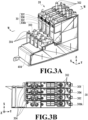
- Fig. 3A and Fig. 3B are schematic configuration diagrams of the ink tank unit 28.
- Fig. 3A is a perspective view
- Fig. 3B is a plan view.
- the substrate 300 is in an attached state in Fig. 3A
- the substrate 300 is in a detached state in Fig. 3B .
- Fig. 4A and Fig. 4B are schematic configuration diagrams of the ink tank 30Bk.
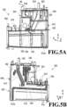
- Fig. 5A and Fig. 5B are schematic configuration diagrams of the ink tank 30C. Note that in Fig. 3A to Fig. 5B , for ease of understanding, the illustration of the plug member 32 is omitted.
- the explanation is given with the directions at the time of being accommodated in the accommodation portion 11 of the printing apparatus 10.
- the ink tank 30C, the ink tank 30M, and the ink tank 30Y, which have the same configuration as each other, and the ink tank 30Bk, which has a larger capacity than the ink tank 30C and the others, are installed side by side along the X direction (see Fig. 3B ).
- the substrate 300 is fixed to each of the ink tanks 30 (see Fig. 3A ).
- the injection ports 302 formed at the tops of the respective ink tanks 30 are designed to be arranged at equal intervals.
- the ink tanks 30 are connected to the tubes 34 at the joint portions 304, respectively.
- the ink tank 30Bk which has a larger capacity than the ink tank 30C, etc., is equipped with the main body portion 402 formed with the width W1 in the X direction and the enlarged portion 404 extending in the X direction on one side of the main body portion 402 in the Y direction, that is, on the back side (see Fig. 4A ).
- the ink tank 30Bk, the ink tank 30C, the ink tank 30M, and the ink tank 30Y are arranged in this order in the +X direction. Therefore, in the present embodiment, the enlarged portion 404 in ink tank 30Bk extends in the +X direction where the other ink tanks 30C, 30M, and 30Y are positioned.
- the main body portion 402 is equipped with the storage chamber 406 that communicates with the enlarged portion 404 and stores ink together with the enlarged portion 404.
- the enlarged portion 404, together with the storage chamber 406 in the ink tank 30Bk, is configured to store ink, and the installation of this enlarged portion 404 allows the ink tank 30Bk to store more ink than the other ink tanks.
- the main body portion 402 is equipped with the buffer portion 408 formed on the upper front side of the storage chamber 406 that serves as an atmospheric communication flow path for the storage chamber 406, and the inlet path 410 that allows ink injected from the injection port 302 to flow into the storage chamber 406 (see Fig. 4B ). Further, the main body portion 402 is equipped with the connecting path 412 that connects the storage chamber 406 to the joint portion 304.
- the opening portion 412a is formed at one end of the connecting path 412, which extends to near the bottom surface of the storage chamber 406, whereas the other end of the connecting path 412 is connected to the joint portion 304. The ink stored in the storage chamber 406 is transferred from the opening portion 412a to the joint portion 304 via the connecting path 412.
- the opening portion 412a is positioned on the front side of the storage chamber 406, and the bottom surface of the storage chamber 406 is shaped to slope gently downward from the back side to the front side. Further, the main body portion 402 is equipped with the insertion portions 414 through which the detection pins 604 can be inserted on the upper back side of the storage chamber 406, and the fixing member 416 that can fix the substrate 300.
- the buffer portion 408 is equipped with five buffer chambers. Specifically, the buffer portion 408 is equipped with the first buffer chamber 420 positioned on the lower back side of the buffer portion 408, the second buffer chamber 422 positioned on the lower front side of the buffer portion 408, and the third buffer chamber 424 positioned on the upper side of the first buffer chamber 420. Further, the buffer portion 408 is equipped with the fourth buffer chamber 426 positioned on the upper back side of the second buffer chamber 422, and the fifth buffer chamber 428 positioned on the upper front side of the second buffer chamber 422.
- the storage chamber 406 is connected to the first buffer chamber 420 via the small chamber 430.
- the small chamber 430 is positioned on the upper back side of the storage chamber 406 and behind the insertion portion 414 and in front of the enlarged portion 404 in the Y direction.
- the opening 432 is formed on the bottom surface of the small chamber 430, and the small chamber 430 and the storage chamber 406 communicate via this opening 432. Further, the small chamber 430 communicates with the first buffer chamber 420 via the flow path 434, and the first buffer chamber 420 communicates with the second buffer chamber 422 via the flow path 436.
- the second buffer chamber 422 communicates with the third buffer chamber 424 via the flow path 438, and the third buffer chamber 424 communicates with the fourth buffer chamber 426 via the flow path 440.
- the fourth buffer chamber 426 communicates with the fifth buffer chamber 428 via the flow path 442, and the fifth buffer chamber 428 communicates with the outside of the ink tank 30Bk via the atmospheric communication port 444.
- the storage chamber 406 is configured to communicate with the outside via the small chamber 430, the first buffer chamber 420, the second buffer chamber 422, the third buffer chamber 424, the fourth buffer chamber 426, and the fifth buffer chamber 428.
- the first buffer chamber 420 opens in the +X direction
- the flow path 436 is configured to open in a different direction than the first buffer chamber 420 (that is, in the -X direction).
- the second buffer chamber 422, the third buffer chamber 424, and the fourth buffer chamber 426 open in the -X direction
- the flow path 438, the flow path 440, and the flow path 442 open in the +X direction.
- the configuration is such that it is difficult for the ink stored in the storage chamber 406 to leak out to the outside via the atmospheric communication port 444, no matter what the posture of the ink tank 30Bk is.
- a film (not illustrated in the drawings) is welded to the main body portion 402 and the enlarged portion 404, and on the side surface of the right side, another film (not illustrated in the drawings) is welded to the main body portion 402.
- the right side surface of the enlarged portion 404 is configured of the same material as the main body portion 402 and the like, and is closed off.
- the configuration of the ink tank 30C is basically the same as that of the ink tank 30Bk, except for the arrangement of the communication port and not being equipped with a configuration corresponding to the enlarged portion 404.
- the ink tank 30C which has a smaller capacity than the ink tank 30Bk, has the main body portion 502 formed with the width W2 which is smaller than the width W1 in the X direction (see Fig. 5A ).
- the main body portion 502 is equipped with the storage chamber 506 for storing ink. Note that, differing from the ink tank 30Bk, a configuration corresponding to the enlarged portion 404 is not installed in the ink tank 30C, and the ink tank 30C is formed smaller than the ink tank 30Bk in the X direction. Therefore, the amount of ink that can be stored in the storage chamber 506 is less than the amount of ink that can be stored in the storage chamber 406.
- the main body portion 502 is equipped with the buffer portion 508 formed on the upper front side of the storage chamber 506 to serve as an atmospheric communication flow path, and the inlet path 510 that allows ink injected from the injection port 302 to flow into the storage chamber 506 (see Fig. 5B ). Further, the main body portion 502 is equipped with the connecting path 512 that connects the storage chamber 506 to the joint portion 304.
- the opening portion 512a is formed at one end of the connecting path 512, which extends to near the bottom surface of the storage chamber 506, whereas the other end of the connecting path 512 is connected to the joint portion 304. Ink stored in the storage chamber 506 is transferred from the opening portion 512a to the joint portion 304 via the connecting path 512.
- the opening portion 512a is located on the front side of the storage chamber 506, and the bottom surface of the storage chamber 506 is shaped to slope gently downward from the back side to the front side. Further, the main body portion 502 is equipped with the insertion portions 514 through which the detection pins 604 can be inserted on the upper back side of the storage chamber 506, and the fixing member 516 that can fix the substrate 300.
- the buffer portion 508 is equipped with five buffer chambers. Specifically, the buffer portion 508 is equipped with the first buffer chamber 520 positioned on the lower back side of the buffer portion 508, the second buffer chamber 522 positioned on the lower front side of the buffer portion 508, and the third buffer chamber 524 positioned on the upper side of the first buffer chamber 520. Further, the buffer portion 508 is equipped with the fourth buffer chamber 526 positioned on the upper back side of the second buffer chamber 522, and the fifth buffer chamber 528 positioned on the upper front side of the second buffer chamber 522.
- the storage chamber 506 communicates with the first buffer chamber 520 via the opening 532.
- the opening 532 is positioned on the upper surface of the storage chamber 506 and is positioned at the approximate center of the storage chamber 506 in the Y direction.
- the first buffer chamber 520 communicates with the second buffer chamber 522 via the flow path 536
- the second buffer chamber 522 communicates with the third buffer chamber 524 via the flow path 538
- the third buffer chamber 524 communicates with the fourth buffer chamber 526 via the flow path 540.
- the fourth buffer chamber 526 communicates with the fifth buffer chamber 528 via the flow path 542
- the fifth buffer chamber 528 communicates with the outside of the ink tank 30C via the atmospheric communication port 544.
- the storage chamber 506 is configured to communicate with the outside via the first buffer chamber 520, the second buffer chamber 522, the third buffer chamber 524, the fourth buffer chamber 526, and the fifth buffer chamber 528.
- the first buffer chamber 520 opens in the +X direction
- the flow path 536 is configured to open in a different direction than the first buffer chamber 520 (that is, in the -X direction).
- the second buffer chamber 522, the third buffer chamber 524, and the fourth buffer chamber 526 open in the -X direction
- the flow path 538, the flow path 540, and the flow path 542 open in the +X direction.
- the configuration is such that it is difficult for the ink stored in the storage chamber 506 to leak out to the outside via the atmospheric communication port 544, no matter what the posture of the ink tank 30C is.
- a film (not illustrated in the drawings) is welded to each side of the main body portion 502, which seals the storage chamber 506, each buffer chamber in the buffer portion 508, the inlet path 510, the connecting path 512, and the flow paths communicating with each buffer chamber.
- the ink tank 30C, the ink tank 30M, and the ink tank 30Y are installed side by side in the X direction along with the ink tank 30Bk.
- the ink tanks 30C, 30M, and 30Y which have the same configuration, are arranged aligned with respect to the Y direction.
- the ink tank 30Bk is formed with only the enlarged portion 404 larger in the Y direction. Therefore, in the ink tank unit 28, the ink tanks 30C, 30M, 30Y, and the main body portion 402 of the ink tank 30Bk are arranged with their positions aligned with respect to the Y direction.
- the enlarged portion 404 of the ink tank 30Bk is arranged in a position that overlaps with at least one of the ink tanks 30C, 30M, and 30Y in the X direction. In other words, the enlarged portion 404 overlaps with at least one of the ink tanks 30C, 30M, and 30Y as viewed from the Y direction. Furthermore, the enlarged portion 404 is positioned adjacent to the back sides of the overlapped ink tanks as viewed from the front side of the printing apparatus 10 (see Fig. 3A ).
- the enlarged portion 404 is configured to overlap with at least one of the ink tanks 30C, 30M, and 30Y. Therefore, the number of overlapped ink tanks and the amount of overlap in the X direction can be adjusted by changing the size and shape of the enlarged portion 404. Further, for example, in a case where the enlarged portion 404 overlaps with the ink tank 30C as viewed from the Y direction, it is sufficient for the enlarged portion 404 to overlap with at least a portion of the ink tank 30C.
- the enlarged portion 404 overlaps with the ink tanks 30C, 30M, and 30Y, it is sufficient for the enlarged portion 404 to overlap with at least a portion of the ink tank 30C, the ink tank 30M, and the ink tank 30Y as viewed from the Y direction.
- the size (W1) of the main body portion 402 of the ink tank 30Bk in the X direction is larger than the size (W2) of the main body portion 502 of the ink tank 30C in the X direction.
- the size of the ink tank 30Bk in the X direction can be made to match W2 while maintaining the capacity of the ink tank 30Bk.
- the capacity of the ink tank 30Bk is about 70 ml, and the capacity of the ink tanks 30C, 30M, and 30Y is about 40 ml.
- the ratio of the Bk ink used in business documents is high.
- the ink tank 30Bk which stores the Bk ink, is formed with a larger capacity than the ink tanks that store the other chromatic color inks.
- FIG. 6A and Fig. 6B are enlarged views of the vicinity of the small chamber 430 of the ink tank 30Bk.
- Fig. 6A is a perspective view
- Fig. 6B is a view from the A arrow of the vicinity of the small chamber 430 in Fig. 6A .
- Fig. 7 is a left side view of the ink tank 30Bk.
- the small chamber 430 installed between the storage chamber 406 and the buffer portion 408 is formed to allow the ink stored in the storage chamber 406 to flow in in a case where the ink tank 30Bk is in a different posture from that of the posture during use, even without air expansion or the like inside the storage chamber 406.
- the posture during use is, for example, the posture as the ink tank unit 28 is accommodated in the accommodation portion 11 of the printing apparatus 10 placed on a horizontal surface (see Fig. 3A ). Further, in the explanation given below, a "different posture from the posture during use" is appropriately referred to as an "abnormal posture.”
- the opening 432 is shaped as a slit extending in the X direction and is large enough that the ink stored in the storage chamber 406 does not form a meniscus (see Fig. 6A ).
- the ink tank 30Bk assumes an abnormal posture and the opening 432 is below the liquid surface of the ink, a gas-liquid exchange occurs at the opening 432, and the small chamber 430 is filled with ink.
- the small chamber 430 functions as an inflow chamber into which ink from the storage chamber 406 can flow.
- the communication port 602 that communicates with the flow path 434 is formed in the small chamber 430, and the small chamber 430 communicates with the first buffer chamber 420 of the buffer portion 408 via the communication port 602 and the flow path 434 (see Fig. 6B ).
- the size, or in other words, the opening size of the communication port 602 is a size which allows the ink stored in the storage chamber 406 to form a meniscus at the communication port 602.
- the size of the communication port 602 is, for example, 1.6 mm in the Y direction and 2.0 mm in the Z direction.
- ink does not flow from the communication port 602 into the flow path 434 and does not flow out to the first buffer chamber 420 if ink simply flows into the small chamber 430.
- a pressure change occurs inside the storage chamber 406, such as the expansion of air inside the storage chamber 406 while the ink in the small chamber 430 is forming a meniscus at the communication port 602, the meniscus is broken and the ink flows out of the communication port 602 into the first buffer chamber 420 via the flow path 434.
- the buffer portion 408 is configured to be able to accommodate the ink that cannot be held in the storage chamber 406 due to the expansion of air inside the storage chamber 406, or the like, in a case where the ink tank 30Bk is in an abnormal posture.
- the buffer portion 408 functions as an accommodation chamber that can accommodate the liquid that has flowed out of the storage chamber 406.
- the communication port 602 is designed to be positioned at the center of the inner volume of the storage chamber 406 in the Y direction. This reduces the difference in the amount of the ink flowing into the communication port 602 due to tilting, even if the air inside the storage chamber 406 expands at the time where, for example, the front side of the ink tank 30Bk is in a posture tilted downward or the back side of the ink tank 30Bk is in a posture tilted downward.
- the center of the inner volume is the position of the hypothetical line 702 (see Fig. 7 ) passing through the communication port 602, where the storage chamber 406 is divided in the Y direction such that the inner volume on one side is equal to the inner volume on the other side.
- the opening 432 is also formed at a position that approximately matches the communication port 602 in the Y direction.
- the opening 532 of the ink tank 30C is similarly designed to be positioned at the center of the inner volume of the storage chamber 506 in the Y direction (see Fig. 5A ). Note that, in the ink tank 30Bk, since the enlarged portion 404 is installed on the back side, the center of the inner volume is positioned further to the back side by the inner volume of the enlarged portion 404. As a result, in the ink tank 30Bk, with respect to the Y direction, the communication port 602 and the opening 432 are positioned between the wall 704 on the back side of the buffer portion 408 and the wall 706 on the back side of the enlarged portion 404.
- the center of the inner volume of the storage chamber 506 is positioned at or in the vicinity of the center position of the storage chamber 506 with respect to the Y direction. That is, in the ink tank 30C, the opening 532 is positioned in front of the back side surface of the buffer portion 508.
- the detection pins 604 capable of detecting if the liquid stored in the storage chamber 406 becomes a predetermined amount or less.
- a pair of the detection pins 604 is inserted through the insertion portion 414, and the detection pins 604 are positioned inside the storage chamber 406. Further, in the ink tank 30C, the detection pins 604 are inserted through the insertion portions 514, and the detection pins 604 are positioned inside the storage chamber 506. Detection using the detection pins 604 is performed by electrification between the pairs of detection pins 604. As electrification happens via the ink if both of the detection pins 604 are immersed in ink, it is possible to detect that more ink than the predetermined amount is stored inside the storage chamber 406.
- the herein-described center of the storage chamber 406 is the position between the wall 708 on the front side of the main body portion 402 and the wall 706. If the detection pins 604 are positioned near the wall 706, the position of the liquid surface of the ink near the detection pins 604 in the Z direction will be significantly different in a case where the ink tank 30Bk is tilted to the front side, compared with a case where the ink tank 30Bk is tilted to the back side.
- the detection pins 604 are positioned in this order in the +Y direction.
- the detection pins 604 are electrically connected to the circuit installed on the substrate 300 due to the compression spring 802 (see Fig. 8 ) made from metal or another conductive material.
- the substrate 300 is connected to the power supply by a cable from a connector. Voltage is applied to the detection pins 604 from this power supply, and it is determined by the control portion 200 whether there is or is not electrification, or in other words, whether or not the ink in the storage chamber is the predetermined amount or less, based on the resistance value between the two detection pins 604.
- the two detection pins are used as the detection pin for detecting the remaining amount of the liquid, but there is no limitation as such.
- multiple detection pins with different lengths in the Z direction may be used, so that the remaining amount of the liquid is detected by combinations of two of the multiple detection pins where no electrification happens.
- Fig. 8 is a cross-sectional view taken along the line VIII-VIII in Fig. 3A .
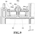
- Fig. 9 is an enlarged view of the vicinity of the fixing member in Fig. 8 .
- the fixing member 416 and the fixing member 516 installed in the respective ink tanks 30 are the configuration for fixing to the respective ink tanks 30 the substrate 300, on which a circuit and the like are formed to output a signal from the detection pins 604 installed in the respective ink tanks 30 to the control portion 200. Note that, since both the fixing member 416 and the fixing member 516 have the same configuration, in the following explanation, an explanation is given about the fixing member 516 and an explanation of the fixing member 416 is omitted.
- the fixing member 516 extends in the ink tank 30C perpendicular to the plane 800 in which the insertion portions 514, through which the detection pins 604 are inserted, is formed. In the present embodiment, the fixing member 516 extends parallel to the Z direction. The fixing member 516 is positioned between the two detection pins 604 with respect to the Y direction (see Fig. 8 ). The fixing member 516 is equipped with the axial portion 902 extending in the Z direction and the regulating portion 904 at the tip of the axial portion 902 that regulates the removal of the inserted substrate 300 (see Fig. 9 ).
- the substrate 300 while being fixed by the fixing member 516, is electrically connected to the detection pins 604 via the compression spring 802.
- the regulating portion 904 can be inserted into the hole portion 310 (see Fig. 3A and Fig. 9 ) installed in the substrate 300 for the insertion of the fixing member 516, and the regulating portion 904 is configured so that movement in the upward direction of the substrate 300 caused by the biasing force of the compression spring 802 after insertion can be regulated.
- the regulating portion 904 is formed in an arrowhead shape and is formed to gradually widen in the Y direction from the tip 902a of the axial portion 902 toward the lower side.
- the regulating portion 904 is equipped with the returning portion 904a extending to the lower front side from the tip 902a of the axial portion 902 and the returning portion 904b extending to the lower back side.
- the returning portions 904a and 904b are connected to the axial portion 902 only at the tip 902a.
- the returning portions 904a and 904b flex toward the axial portion 902 side, that is, toward the center of the fixing member 516, by pressure from the upper side to the lower side (the opposite direction of the direction of biasing by the compression spring 802), and the flexion is resolved once the pressure is released. Further, the returning portions 904a and 904b flex in the direction away from the axial portion 902, that is, in the direction away from the center of the fixing member 516, due to pressure from the lower side to the upward side.
- the fixing member 516 For fixing the substrate 300 to the fixing member 516, the fixing member 516 is inserted into the hole portion 310 from the upper side. At this time, the returning portions 904a and 904b of the regulating portion 904 flex toward the axial portion 902 side due to the movement of the hole portion 310 toward the lower side, allowing the insertion into the hole portion 310, and at the timing where the hole portion 310 is positioned under the regulating portion 904, the flexion is resolved.
- the tip 904aa of the returning portion 904a becomes positioned outside of the hole portion 310, that is, on the front side of the circumference of the hole portion 310
- the tip 904ba of the returning portion 904b becomes positioned outside of the hole portion 310, that is, on the back side of the circumference of the hole portion 310.
- the fixing member 516 functions as a regulating member that regulates movement of the substrate 300 to the upper side due to the compression spring 802.
- the fixing member 516 and the compression spring 802 which is a biasing member, work together to function as a fixing portion to fix the substrate 300.
- fixing member 516 By forming the fixing member 516 in this way, fixing the substrate 300 to the ink tank 30C becomes easy and also it becomes difficult for the substrate 300 to be removed from the ink tank 30C. Therefore, it is difficult for the substrate 300 to detach from the ink tank unit 28 to which the substrate 300 is fixed together with the fixing member 416, which has the same configuration as the fixing member 516. Further, since the fixing members 416 and 516 and the compression spring 802 work together to fix the substrate 300, displacement of the arrangement position of the substrate 300 due to vibration of the apparatus or the like is suppressed, and damage to the members is also reduced.
- an ink tank installed side by side together with multiple ink tanks in the X direction is equipped with a storage chamber formed to overlap with at least one of the other ink tanks as viewed from the Y direction.
- This makes it possible to suppress the ink tank unit becoming a large size in the X direction, where the ink tanks are installed side by side, and makes it possible to suppress an expansion of the space for accommodating the ink tank unit in the X direction.
- by changing the shape of the enlarged portion it becomes possible to change the inner volume ratio between the larger capacity ink tank and the other ink tanks, thereby increasing the degree of freedom in setting the ink capacity ratio between these two types of ink tanks.
- a small chamber is provided between the storage chamber and a buffer portion that is capable of accommodating ink that cannot be held in the storage chamber, which makes the ink flow easily in and out of the reservoir portion. Furthermore, in the small chamber, a communication port is installed that communicates with a flow path connected to the buffer portion, and the size of the opening of the communication port is designed to be a size which allows the ink to form a meniscus.
- the communication port is positioned at the center of the inner volume of the storage chamber. This makes it possible to suppress the amount of ink flowing into the communication port, even if the air in the storage chamber expands at the time where the ink tank is in an abnormal posture.
- a compression spring which is arranged above the detection pins that detect the remaining amount of the ink in the storage chamber, biases the substrate on which the circuit is formed to the upper side, while the fixing member regulates movement of the substrate toward the upper side, thereby fixing the substrate to the ink tank.
- Fig. 12 is a diagram illustrating an example of the ink tank unit with the substrate fixed by another form of fixing mechanism.
- Fig. 13A is a cross-sectional view taken along the XIIIa-XIIIa line of Fig. 12
- Fig. 13B is a cross-sectional view taken along the XIIIb-XIIIb line of Fig. 12 .
- the substrate 1212 is fixed by the claw portion 1220 (see Fig.12 ).
- the two detection pins 604 are installed side by side along the X direction (see Fig. 13A ). Further, the detection pins 604 are electrically connected to the circuit formed on the substrate 1212 by the compression spring 802.
- the claw portion 1220 is equipped with the first claw portion 1230 that abuts on the top surface of the front long side of the substrate 1212, which extends and is fixed in the X direction in the ink tank unit 1210. Further, the claw portion 1220 is equipped with the second claw portion 1232 that abuts on the top surface of the back long side of the substrate 1212.
- the first claw portion 1230 and the second claw portion 1232 are arranged, for example, at positions that do not overlap with each other in the X direction.
- the pair of detection pins 604 is positioned between the first claw portion 1230 and the second claw portion 1232 in the X direction.
- the first claw portion 1230 is installed on the wall 1208 positioned on the back side of the buffer portion and extends to the lower back side from the wall 1208.
- the second claw portion 1232 extends to the lower front side from the tip of the erect portion 1234 erected on the plane 1209 which is parallel to the XY plane and is positioned on the back side of the wall 1208.
- the first claw portion 1230 flexes toward the wall 1208 due to pressure from the upper side to the lower side
- the second claw portion 1232 flexes toward the erect portion 1234 due to pressure from the upper side. Then, if these pressures are released, the flexions that occur in the first claw portion 1230 and the second claw portion 1232 are resolved. Further, the first claw portion 1230 flexes away from the wall 1208 due to pressure from the lower side to the upper side. Furthermore, the second claw portion 1232 flexes away from the erect portion 1234 due to pressure from the lower side.
- the substrate 1212 is pressed from the upper side of the claw portion 1220.
- the first claw portion 1230 flexes toward the wall 1208 side and the second claw portion 1232 flexes toward the erect portion 1234 side, and the flexions are resolved at the timing where the substrate 1212 is positioned lower than the claw portion 1220.
- the interval in the Y direction between the wall 1208, which is a supporting member for the first claw portion 1230, and the erect portion 1234, which is a supporting member for the second claw portion 1232 is equal to or longer than the length of the substrate 1212 in the Y direction.
- the length of the substrate 1212 in the Y direction is the length in the Y direction in the area where the substrate 1212 is fixed to each of the ink tanks by the claw portions 1220.
- the interval in the Y direction between the tip 1230a of the first claw portion 1230 and the tip 1232a of the second claw portion 1232 is shorter than the length of the substrate 1212 in the Y direction.
- the tip 1230a of the first claw portion 1230 and the tip 1232a of the second claw portion 1232 can be positioned on the front surface of the substrate 1212 with the substrate 1212 in a state positioned lower than the claw portion 1220.
- the substrate 1212 is biased upward by the compression spring 802, but upward movement is regulated by the first claw portion 1230 and the second claw portion 1232.
- each of the ink tanks may be configured to be equipped with one claw portion.
- adjacent ink tanks should have claw portions installed at different positions in the Y direction.
- the ink tanks 1202 and 1206 would only be equipped with the first claw portion 1230, and the ink tank 1204 would only be equipped with the second claw portion 1232.
- the fixing member 416 for fixing the substrate 300 is installed in each of the ink tanks of the ink tank unit 28, which is formed so that the particular ink tank among the four ink tanks 30 overlaps with at least part of the other ink tanks.
- the fixing member 416 is not limited to being formed only in this kind of ink tank unit 28, but may be formed in each ink tank of an ink tank unit configured with multiple ink tanks with the same shape as each other.
- the printing apparatus 10 is what is termed as a serial-scan type printing apparatus that performs printing by ejecting ink, while moving a print head in the X direction, onto a print medium conveyed in the Y direction, but there is no limitation as such.
- the printing apparatus to which the present invention can be applied may be, for example, what is termed a line-type printing apparatus that is equipped with a print head with a nozzle array formed in the X direction with a length corresponding to the width of the printable print medium, and that performs printing from the fixed print head onto the print medium conveyed in the Y direction.
- one ink tank is installed with the storage chamber formed larger due to the enlarged portion, but there is no limitation as such, and a plurality of such ink tanks may be installed.
- the enlarged portion may extend in the +X direction to overlap with the ink tank 30C in the X direction
- an enlarged portion may extend in the -X direction to overlap with the ink tank 30M in the X direction.
- three ink tanks are installed without the enlarged portion 404 installed, but there is no limitation as such. There may be one, two, or even four or more ink tanks without the enlarged portion 404 installed.
Landscapes
- Ink Jet (AREA)
Applications Claiming Priority (1)
| Application Number | Priority Date | Filing Date | Title |
|---|---|---|---|
| JP2023122180A JP2025018462A (ja) | 2023-07-27 | 2023-07-27 | 記録装置およびタンク |
Publications (1)
| Publication Number | Publication Date |
|---|---|
| EP4497604A1 true EP4497604A1 (de) | 2025-01-29 |
Family
ID=92043077
Family Applications (1)
| Application Number | Title | Priority Date | Filing Date |
|---|---|---|---|
| EP24190832.6A Pending EP4497604A1 (de) | 2023-07-27 | 2024-07-25 | Druckvorrichtung |
Country Status (5)
| Country | Link |
|---|---|
| US (1) | US20250033366A1 (de) |
| EP (1) | EP4497604A1 (de) |
| JP (1) | JP2025018462A (de) |
| KR (1) | KR20250017674A (de) |
| CN (1) | CN119369833A (de) |
Citations (7)
| Publication number | Priority date | Publication date | Assignee | Title |
|---|---|---|---|---|
| US20160263905A1 (en) * | 2015-03-12 | 2016-09-15 | Seiko Epson Corporation | Tank, tank unit, liquid ejection system, and liquid ejection apparatus |
| US20170120609A1 (en) * | 2015-10-30 | 2017-05-04 | Canon Kabushiki Kaisha | Printing apparatus and liquid storage member |
| US20180111377A1 (en) * | 2015-03-31 | 2018-04-26 | Seiko Epson Corporation | Liquid supply apparatus and liquid consuming apparatus |
| JP2018069696A (ja) | 2016-11-04 | 2018-05-10 | セイコーエプソン株式会社 | 液体噴射装置 |
| US20180244056A1 (en) * | 2015-03-12 | 2018-08-30 | Seiko Epson Corporation | Tank, tank unit, and liquid ejection system |
| US20200316957A1 (en) * | 2019-04-03 | 2020-10-08 | Canon Kabushiki Kaisha | Inkjet printing apparatus and ink tank |
| US20220032633A1 (en) * | 2020-07-31 | 2022-02-03 | Canon Kabushiki Kaisha | Printing apparatus and liquid storing container |
Family Cites Families (3)
| Publication number | Priority date | Publication date | Assignee | Title |
|---|---|---|---|---|
| JPH10226086A (ja) * | 1997-02-12 | 1998-08-25 | Oki Data:Kk | インクジェットプリンタ |
| US6727115B2 (en) * | 2001-10-31 | 2004-04-27 | Hewlett-Packard Development Company, L.P. | Back-side through-hole interconnection of a die to a substrate |
| JP6880734B2 (ja) * | 2016-12-28 | 2021-06-02 | ブラザー工業株式会社 | インクジェット記録装置 |
-
2023
- 2023-07-27 JP JP2023122180A patent/JP2025018462A/ja active Pending
-
2024
- 2024-07-20 US US18/778,962 patent/US20250033366A1/en active Pending
- 2024-07-22 KR KR1020240096118A patent/KR20250017674A/ko active Pending
- 2024-07-23 CN CN202410992349.1A patent/CN119369833A/zh active Pending
- 2024-07-25 EP EP24190832.6A patent/EP4497604A1/de active Pending
Patent Citations (7)
| Publication number | Priority date | Publication date | Assignee | Title |
|---|---|---|---|---|
| US20160263905A1 (en) * | 2015-03-12 | 2016-09-15 | Seiko Epson Corporation | Tank, tank unit, liquid ejection system, and liquid ejection apparatus |
| US20180244056A1 (en) * | 2015-03-12 | 2018-08-30 | Seiko Epson Corporation | Tank, tank unit, and liquid ejection system |
| US20180111377A1 (en) * | 2015-03-31 | 2018-04-26 | Seiko Epson Corporation | Liquid supply apparatus and liquid consuming apparatus |
| US20170120609A1 (en) * | 2015-10-30 | 2017-05-04 | Canon Kabushiki Kaisha | Printing apparatus and liquid storage member |
| JP2018069696A (ja) | 2016-11-04 | 2018-05-10 | セイコーエプソン株式会社 | 液体噴射装置 |
| US20200316957A1 (en) * | 2019-04-03 | 2020-10-08 | Canon Kabushiki Kaisha | Inkjet printing apparatus and ink tank |
| US20220032633A1 (en) * | 2020-07-31 | 2022-02-03 | Canon Kabushiki Kaisha | Printing apparatus and liquid storing container |
Also Published As
| Publication number | Publication date |
|---|---|
| US20250033366A1 (en) | 2025-01-30 |
| KR20250017674A (ko) | 2025-02-04 |
| JP2025018462A (ja) | 2025-02-06 |
| CN119369833A (zh) | 2025-01-28 |
Similar Documents
| Publication | Publication Date | Title |
|---|---|---|
| KR100519155B1 (ko) | 교환가능한 잉크 용기 | |
| EP0839660B1 (de) | Verbindungselement für eine Patrone in einem Tintenstrahldrucker | |
| US9033478B2 (en) | Liquid accommodation body and accommodation body unit | |
| KR20010013265A (ko) | 교환가능한 잉크 용기 및 오프-축형 프린팅 시스템과오프-축형 프린팅 시스템내로 잉크 용기를 삽입하는 방법 | |
| EP4197797B1 (de) | Flüssigkeitsausstosskopf und flüssigkeitsausstossvorrichtung | |
| CN114643781B (zh) | 喷墨打印设备和墨罐 | |
| US20120127231A1 (en) | Image recording apparatus | |
| US20070040874A1 (en) | Liquid container | |
| JPWO2010041553A1 (ja) | インクジェット記録装置 | |
| US20250033366A1 (en) | Printing apparatus | |
| US10286669B2 (en) | Liquid cartridge having air communication pipe and liquid-consuming device using the same | |
| CN107878031B (zh) | 液体喷射设备和液体供应单元 | |
| CN117087333A (zh) | 液体喷射头和液体喷射装置 | |
| US10457064B2 (en) | Liquid consumption apparatus having cartridge, cartridge attachment section provided with tank, and consuming device | |
| JP5875288B2 (ja) | 液体噴射装置 | |
| US10336084B2 (en) | Liquid cartridge and image forming apparatus using the same | |
| US11577518B2 (en) | Printer and method for detecting abnormal event in printer | |
| US12023928B2 (en) | Liquid discharging head | |
| CN109747270B (zh) | 液体喷射头以及液体喷射记录装置 | |
| JP7155778B2 (ja) | 液体吐出装置 | |
| EP3437875B1 (de) | Flüssigkeitsverbrauchsvorrichtung mit kartusche, kartuschenbefestigungsabschnitt mit einem behälter und verbrauchsvorrichtung | |
| JP5397053B2 (ja) | インクジェット記録装置 | |
| JP2007160714A (ja) | 液体噴射装置 | |
| JP2005288769A (ja) | 液体噴射装置および液体噴射装置のクリーニング方法 | |
| JP2006102984A (ja) | 液体噴射装置 |
Legal Events
| Date | Code | Title | Description |
|---|---|---|---|
| PUAI | Public reference made under article 153(3) epc to a published international application that has entered the european phase |
Free format text: ORIGINAL CODE: 0009012 |
|
| STAA | Information on the status of an ep patent application or granted ep patent |
Free format text: STATUS: THE APPLICATION HAS BEEN PUBLISHED |
|
| AK | Designated contracting states |
Kind code of ref document: A1 Designated state(s): AL AT BE BG CH CY CZ DE DK EE ES FI FR GB GR HR HU IE IS IT LI LT LU LV MC ME MK MT NL NO PL PT RO RS SE SI SK SM TR |
|
| STAA | Information on the status of an ep patent application or granted ep patent |
Free format text: STATUS: REQUEST FOR EXAMINATION WAS MADE |
|
| 17P | Request for examination filed |
Effective date: 20250729 |