EP4497527A1 - Laser processing apparatus - Google Patents
Laser processing apparatus Download PDFInfo
- Publication number
- EP4497527A1 EP4497527A1 EP24178124.4A EP24178124A EP4497527A1 EP 4497527 A1 EP4497527 A1 EP 4497527A1 EP 24178124 A EP24178124 A EP 24178124A EP 4497527 A1 EP4497527 A1 EP 4497527A1
- Authority
- EP
- European Patent Office
- Prior art keywords
- laser
- gas
- controller
- irradiation
- injection
- Prior art date
- Legal status (The legal status is an assumption and is not a legal conclusion. Google has not performed a legal analysis and makes no representation as to the accuracy of the status listed.)
- Pending
Links
Images


Classifications
-
- B—PERFORMING OPERATIONS; TRANSPORTING
- B23—MACHINE TOOLS; METAL-WORKING NOT OTHERWISE PROVIDED FOR
- B23K—SOLDERING OR UNSOLDERING; WELDING; CLADDING OR PLATING BY SOLDERING OR WELDING; CUTTING BY APPLYING HEAT LOCALLY, e.g. FLAME CUTTING; WORKING BY LASER BEAM
- B23K26/00—Working by laser beam, e.g. welding, cutting or boring
- B23K26/08—Devices involving relative movement between laser beam and workpiece
- B23K26/0869—Devices involving movement of the laser head in at least one axial direction
- B23K26/0876—Devices involving movement of the laser head in at least one axial direction in at least two axial directions
- B23K26/0884—Devices involving movement of the laser head in at least one axial direction in at least two axial directions in at least three axial directions, e.g. manipulators, robots
-
- B—PERFORMING OPERATIONS; TRANSPORTING
- B23—MACHINE TOOLS; METAL-WORKING NOT OTHERWISE PROVIDED FOR
- B23K—SOLDERING OR UNSOLDERING; WELDING; CLADDING OR PLATING BY SOLDERING OR WELDING; CUTTING BY APPLYING HEAT LOCALLY, e.g. FLAME CUTTING; WORKING BY LASER BEAM
- B23K26/00—Working by laser beam, e.g. welding, cutting or boring
- B23K26/08—Devices involving relative movement between laser beam and workpiece
- B23K26/082—Scanning systems, i.e. devices involving movement of the laser beam relative to the laser head
-
- B—PERFORMING OPERATIONS; TRANSPORTING
- B23—MACHINE TOOLS; METAL-WORKING NOT OTHERWISE PROVIDED FOR
- B23K—SOLDERING OR UNSOLDERING; WELDING; CLADDING OR PLATING BY SOLDERING OR WELDING; CUTTING BY APPLYING HEAT LOCALLY, e.g. FLAME CUTTING; WORKING BY LASER BEAM
- B23K26/00—Working by laser beam, e.g. welding, cutting or boring
- B23K26/14—Working by laser beam, e.g. welding, cutting or boring using a fluid stream, e.g. a jet of gas, in conjunction with the laser beam; Nozzles therefor
- B23K26/1435—Working by laser beam, e.g. welding, cutting or boring using a fluid stream, e.g. a jet of gas, in conjunction with the laser beam; Nozzles therefor involving specially adapted flow-control means
- B23K26/1437—Working by laser beam, e.g. welding, cutting or boring using a fluid stream, e.g. a jet of gas, in conjunction with the laser beam; Nozzles therefor involving specially adapted flow-control means for flow-rate control
-
- B—PERFORMING OPERATIONS; TRANSPORTING
- B23—MACHINE TOOLS; METAL-WORKING NOT OTHERWISE PROVIDED FOR
- B23K—SOLDERING OR UNSOLDERING; WELDING; CLADDING OR PLATING BY SOLDERING OR WELDING; CUTTING BY APPLYING HEAT LOCALLY, e.g. FLAME CUTTING; WORKING BY LASER BEAM
- B23K26/00—Working by laser beam, e.g. welding, cutting or boring
- B23K26/14—Working by laser beam, e.g. welding, cutting or boring using a fluid stream, e.g. a jet of gas, in conjunction with the laser beam; Nozzles therefor
- B23K26/1435—Working by laser beam, e.g. welding, cutting or boring using a fluid stream, e.g. a jet of gas, in conjunction with the laser beam; Nozzles therefor involving specially adapted flow-control means
- B23K26/1438—Working by laser beam, e.g. welding, cutting or boring using a fluid stream, e.g. a jet of gas, in conjunction with the laser beam; Nozzles therefor involving specially adapted flow-control means for directional control
-
- B—PERFORMING OPERATIONS; TRANSPORTING
- B23—MACHINE TOOLS; METAL-WORKING NOT OTHERWISE PROVIDED FOR
- B23K—SOLDERING OR UNSOLDERING; WELDING; CLADDING OR PLATING BY SOLDERING OR WELDING; CUTTING BY APPLYING HEAT LOCALLY, e.g. FLAME CUTTING; WORKING BY LASER BEAM
- B23K26/00—Working by laser beam, e.g. welding, cutting or boring
- B23K26/14—Working by laser beam, e.g. welding, cutting or boring using a fluid stream, e.g. a jet of gas, in conjunction with the laser beam; Nozzles therefor
- B23K26/1462—Nozzles; Features related to nozzles
- B23K26/1464—Supply to, or discharge from, nozzles of media, e.g. gas, powder, wire
- B23K26/147—Features outside the nozzle for feeding the fluid stream towards the workpiece
-
- B—PERFORMING OPERATIONS; TRANSPORTING
- B23—MACHINE TOOLS; METAL-WORKING NOT OTHERWISE PROVIDED FOR
- B23K—SOLDERING OR UNSOLDERING; WELDING; CLADDING OR PLATING BY SOLDERING OR WELDING; CUTTING BY APPLYING HEAT LOCALLY, e.g. FLAME CUTTING; WORKING BY LASER BEAM
- B23K26/00—Working by laser beam, e.g. welding, cutting or boring
- B23K26/36—Removing material
- B23K26/362—Laser etching
- B23K26/364—Laser etching for making a groove or trench, e.g. for scribing a break initiation groove
-
- B—PERFORMING OPERATIONS; TRANSPORTING
- B23—MACHINE TOOLS; METAL-WORKING NOT OTHERWISE PROVIDED FOR
- B23K—SOLDERING OR UNSOLDERING; WELDING; CLADDING OR PLATING BY SOLDERING OR WELDING; CUTTING BY APPLYING HEAT LOCALLY, e.g. FLAME CUTTING; WORKING BY LASER BEAM
- B23K26/00—Working by laser beam, e.g. welding, cutting or boring
- B23K26/70—Auxiliary operations or equipment
- B23K26/702—Auxiliary equipment
-
- B—PERFORMING OPERATIONS; TRANSPORTING
- B23—MACHINE TOOLS; METAL-WORKING NOT OTHERWISE PROVIDED FOR
- B23K—SOLDERING OR UNSOLDERING; WELDING; CLADDING OR PLATING BY SOLDERING OR WELDING; CUTTING BY APPLYING HEAT LOCALLY, e.g. FLAME CUTTING; WORKING BY LASER BEAM
- B23K26/00—Working by laser beam, e.g. welding, cutting or boring
- B23K26/70—Auxiliary operations or equipment
- B23K26/702—Auxiliary equipment
- B23K26/705—Beam measuring devices
Definitions
- the present disclosure relates to a laser processing apparatus, and more particularly to the technique of removing a spatter in a laser processing apparatus.
- Japanese Patent No. 7081050 discloses the technique of reducing an influence of heat by removing a plume (hot steam) generated when a workpiece made of carbon fiber reinforced plastics (CFRP) is subjected to laser processing.
- a plume in a range of laser-beam irradiation is efficiently removed by subjecting a nozzle portion to fine processing (such as, for example, changing a cross-sectional shape for each of a plurality of flow paths of the nozzle portion) to change a flow velocity of an injected gas depending on the position.
- a spatter which is molten metal
- the spatter is heavy, and thus, the spatter may be accumulated in the processing groove.
- the generation of the spatter leads to a deterioration of quality in welding.
- a spatter adheres to the processing groove and solidifies, which causes a decrease in welding strength.
- An object of the present disclosure is to provide a laser processing apparatus capable of appropriately blowing off a spatter generated by laser processing.
- a laser processing apparatus includes: a laser-beam irradiation device that forms a processing groove in a workpiece by subjecting the workpiece to laser processing while scanning a surface of the workpiece; an injection device that injects a gas in a range of laser-beam irradiation by the laser-beam irradiation device; an actuator that changes a position of injection of the gas by the injection device; and a controller.
- the controller controls the actuator in accordance with a position of irradiation by the laser-beam irradiation device, thereby changing the position of injection of the gas by the injection device.
- Fig. 1 is a diagram schematically showing a configuration of a laser processing apparatus 1 according to the present disclosure.
- Laser processing apparatus 1 includes a laser-beam irradiation device 2, a nozzle 40, a motor 41, and a controller 10.
- Laser-beam irradiation device 2 is a device for subjecting a workpiece 60 placed on a not-shown table to laser processing.
- Laser-beam irradiation device 2 includes a galvano scanner 20 and a laser oscillation device 30.
- the coordinate axes in Fig. 1 correspond to an X axis, a Y axis and a Z axis.
- Galvano scanner 20 includes a lens 21, a scan mirror 22, a motor 23, an encoder 24, and a main body portion 27.
- Scan mirror 22 reflects a laser beam L received from laser oscillation device 30, and outputs laser beam L to lens 21.
- Scan mirror 22 is configured such that the orientation thereof can be changed by motor 23 serving as an actuator, and can change a position of irradiation with laser beam L emitted through lens 21.
- Scan mirror 22 includes, for example, an X scan mirror that can change the position of irradiation in the X direction, and a Y scan mirror that can change the position of irradiation in the Y direction.
- Motor 23 is implemented by, for example, a servo motor, and includes an X-axis motor that rotationally drives the X scan mirror, and a Y-axis motor that rotationally drives the Y scan mirror.
- Encoder 24 serving as a sensor that detects a rotation position is connected to motor 23.
- galvano scanner 20 has lens 21, scan mirror 22, motor 23, and encoder 24 built into main body portion 27, motor 23 and encoder 24 are shown outside main body portion 27 in the figure. As shown in Fig. 1 , galvano scanner 20 forms a processing groove in workpiece 60 by scanning laser beam L on an X-Y plane of workpiece 60.
- Nozzle 40 functions as an injection device that injects a gas W, and is connected to a cylinder 50 serving as a source of gas W through a flow rate adjustment valve 42 serving as an adjustment mechanism that adjusts a flow velocity of gas W.
- the source of gas W may be a device other than cylinder 50, and may be any device as long as it can supply gas W.
- Cylinder 50 is filled with the compressed air, for example.
- Gas W may be a gas other than the air, and may be, for example, an inert gas such as argon.
- Flow rate adjustment valve 42 has such a structure that a degree of opening is changeable. Flow rate adjustment valve 42 adjusts a flow rate of gas W supplied from cylinder 50, based on a signal provided from controller 10. Flow rate adjustment valve 42 is implemented by, for example, a valve, a solenoid valve or the like whose degree of opening is adjustable. Nozzle 40 is connected to motor 41 serving as an actuator.
- Motor 41 is implemented by, for example, a stepping motor. Motor 41 may be implemented by a servo motor. Nozzle 40 and motor 41 are fixed to a support portion 47. Support portion 47 is connected to main body portion 27 of galvano scanner 20. Support portion 47 is connected to a tip of a robot arm, for example.
- Controller 10 is configured to include a central processing unit (CPU) 11, a memory 12 (a read only memory (ROM) and a random access memory (RAM)), a not-shown input/output device for inputting/outputting various signals, and the like.
- CPU 11 loads a program stored in the ROM into the RAM or the like and executes the program.
- the program stored in the ROM is a program describing a procedure of a process executed by controller 10.
- Controller 10 controls each device in accordance with these programs. This control is not limited to processing by software but may be processed by dedicated hardware (electronic circuitry).
- Controller 10 controls laser oscillation device 30 to emit laser beam L to galvano scanner 20. Controller 10 controls motor 23 to change an angle of reflection by scan mirror 22. Controller 10 controls motor 41 to change a position of nozzle 40. Controller 10 controls flow rate adjustment valve 42 to adjust the flow rate of gas W, thereby adjusting the flow velocity of gas W injected from nozzle 40.
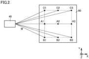
- Fig. 2 is a diagram for illustrating injection of the gas by nozzle 40.
- Nozzle 40 can inject gas W on the X-Y plane of workpiece 60.
- Controller 10 specifies the position of irradiation with laser beam L based on a signal provided from encoder 24. Controller 10 controls motor 41 in accordance with the specified position of irradiation, thereby changing the position of injection of gas W by nozzle 40.
- Position data about the position of injection of gas W corresponding to the position of irradiation by laser-beam irradiation device 2 is stored in memory 12. As shown in Fig. 2 , position data about each of positions A1 to A3, B1 to B3 and C1 to C3 on workpiece 60 is stored in memory 12 as one example of the position data. Controller 10 controls motor 41 based on the position data, thereby changing the position of nozzle 40 into a position corresponding to the position of irradiation with laser beam L.
- Controller 10 can change the flow velocity of gas W, in addition to the position of injection. Controller 10 specifies the position of irradiation with laser beam L based on a signal provided from encoder 24. Controller 10 controls flow rate adjustment valve 42 in accordance with the specified position of irradiation, thereby changing the flow velocity of gas W in nozzle 40.
- Flow velocity data about the flow velocity of gas W corresponding to the position of irradiation by laser-beam irradiation device 2 is stored in memory 12.
- flow velocity data about each of positions A1 to A3, B1 to B3 and C1 to C3 on workpiece 60 is stored in memory 12 as one example of the flow velocity data.
- a distance from nozzle 40 becomes longer in the order of A1 ⁇ A2 ⁇ A3.
- Controller 10 makes the flow velocity lower as the position becomes closer, and makes the flow velocity higher as the position becomes farther.
- Controller 10 controls flow rate adjustment valve 42 based on the flow velocity data, thereby changing the flow velocity of gas W injected from nozzle 40 in accordance with the position of irradiation with laser beam L.
- controller 10 may change the position of injection of gas W by nozzle 40 to correspond to each position, and control flow rate adjustment valve 42 such that the flow velocity becomes higher in the order of position A1 ⁇ A2 ⁇ A3.
- controller 10 may change the position of injection of gas W by nozzle 40 to correspond to each position, and control flow rate adjustment valve 42 such that the flow velocity becomes higher in the order of position B1 ⁇ B2 ⁇ B3.
- controller 10 may change the position of injection of gas W by nozzle 40 to correspond to each position, and control flow rate adjustment valve 42 such that the flow velocity becomes higher in the order of position C1 ⁇ C2 ⁇ C3.
- controller 10 can change the position of injection of gas W by nozzle 40 in accordance with the position of irradiation with laser beam L, and thus, gas W can be injected to an appropriate position corresponding to scanning of laser beam L.
- Controller 10 can change the flow velocity of gas W in nozzle 40 in accordance with the position of irradiation with laser beam L. Specifically, controller 10 makes the flow velocity lower at a point where a distance between nozzle 40 and laser beam L is short than at a point where the distance is long, and makes the flow velocity higher at the point where the distance between nozzle 40 and laser beam L is long than at the point where the distance is short. By doing so, gas W can be injected to the processing groove at constant intensity, and thus, a spatter having a large volume can be appropriately blown off from the processing groove at any position.
- nozzle 40 is fixed, it is conceivable that the intensity of gas W may vary depending on the position where the processing groove is formed. In contrast, in laser processing apparatus 1, nozzle 40 is controlled as described above, such that gas W can be injected at constant intensity to the position corresponding to scanning of laser beam L. As a result, a large-volume spatter generated in the processing groove by irradiation with laser beam L can be appropriately blown off.
- Fig. 3 is a flowchart showing the contents of control performed by controller 10.
- the process of the flowchart in Fig. 3 is repeatedly invoked and executed as a subroutine from a main routine in the control by controller 10.
- step S controller 10 executes the processing of setting, in laser oscillation device 30, an output value of laser beam L corresponding to a processing groove formed in workpiece 60.
- controller 10 executes the processing of setting, in laser oscillation device 30, a position of irradiation with laser beam L corresponding to the processing groove formed in workpiece 60 (S2). For example, controller 10 transmits, to laser oscillation device 30, data indicating how to form the processing groove in workpiece 60.
- controller 10 sets a position of injection of gas W corresponding to the position of irradiation with laser beam L (S3). Specifically, controller 10 makes the setting such that motor 41 is driven based on injection data about the position of injection of gas W corresponding to the position of irradiation by laser-beam irradiation device 2.
- controller 10 sets a flow velocity of gas W corresponding to the position of irradiation with laser beam L (S4). Specifically, controller 10 makes the setting such that a flow rate of gas W is changed by flow rate adjustment valve 42 based on flow velocity data about the flow velocity of gas W corresponding to the position of irradiation by laser-beam irradiation device 2.
- controller 10 performs injection of gas W corresponding to the settings of laser beam L (S5).
- controller 10 performs irradiation of workpiece 60 with laser beam L by laser-beam irradiation device 2 (S6).
- controller 10 detects an actual position of irradiation with laser beam L in workpiece 60 based on an output value of encoder 24 serving as a sensor (S7).
- controller 10 controls nozzle 40 to adjust the injection of gas W such that gas W is injected at appropriate position and flow velocity that allow removal of a spatter from the processing groove (S8).
- controller 10 calculates a position of next irradiation based on the actual position of irradiation when detecting the actual position of irradiation with laser beam L, and performs an adjustment such that injection of gas W is followed by irradiation with laser beam L without delay.
- controller 10 can suitably perform the injection of gas W so as to follow scanning of laser beam L.
- controller 10 determines whether laser processing ends (S9).
- controller 10 determines that laser processing does not end in S9 (NO in S9), controller 10 repeats the processing in S7 and the subsequent steps.
- controller 10 determines that laser processing ends (YES in S9), controller 10 stops the irradiation with laser beam L (S10).
- controller 10 stops the injection of gas W (S11) and returns the process from the subroutine to the main routine.
- Controller 10 may perform the injection of gas W based on a temporarily set position of irradiation with laser beam L, not based on the detection of the position of irradiation with laser beam L. That is, after temporarily setting data about the position of injection and the flow velocity of the gas in accordance with the predetermined position of irradiation with the laser beam, controller 10 may perform injection in accordance with the data until laser processing ends.
- the position of irradiation with laser beam L may be detected based on an image taken by a camera, not by encoder 24. Specifically, controller 10 may specify a high-brightness position in the taken image as the position of irradiation with laser beam L, and perform injection of gas W in accordance with the specified position of irradiation with laser beam L.
- Nozzle 40 may be implemented by a Laval nozzle.
- the Laval nozzle has such a structure that a width becomes narrower from an entrance portion to a central portion and again becomes wider at an exit portion.
- the Laval nozzle can inject a gas having a linearly traveling property at high velocity.
- the position of injection of gas W by nozzle 40 can be changed in accordance with the position of irradiation with laser beam L, and thus, gas W can be injected to an appropriate position corresponding to scanning of laser beam L.
- the flow velocity of gas W in nozzle 40 can be changed in accordance with the position of irradiation with laser beam L, and thus, gas W can be injected at an appropriate flow velocity to the position corresponding to scanning of laser beam L.
Landscapes
- Physics & Mathematics (AREA)
- Optics & Photonics (AREA)
- Engineering & Computer Science (AREA)
- Plasma & Fusion (AREA)
- Mechanical Engineering (AREA)
- Robotics (AREA)
- Fluid Mechanics (AREA)
- Laser Beam Processing (AREA)
Abstract
Description
- This nonprovisional application is based on
Japanese Patent Application No. 2023-089555 filed on May 31, 2023 - The present disclosure relates to a laser processing apparatus, and more particularly to the technique of removing a spatter in a laser processing apparatus.
- There is known a laser processing apparatus that forms a processing groove in a workpiece by using a laser beam.
Japanese Patent No. 7081050 Japanese Patent No. 7081050 - When metal is used in a workpiece, a spatter, which is molten metal, may be generated in a processing groove as a result of formation of the processing groove by laser processing. Unlike a plume, the spatter is heavy, and thus, the spatter may be accumulated in the processing groove. The generation of the spatter leads to a deterioration of quality in welding. For example, in such dissimilar material welding that a molten resin enters a processing groove to weld the metal and the resin, a spatter adheres to the processing groove and solidifies, which causes a decrease in welding strength. Although the technique disclosed in
Japanese Patent No. 7081050 - An object of the present disclosure is to provide a laser processing apparatus capable of appropriately blowing off a spatter generated by laser processing.
- A laser processing apparatus according to the present disclosure includes: a laser-beam irradiation device that forms a processing groove in a workpiece by subjecting the workpiece to laser processing while scanning a surface of the workpiece; an injection device that injects a gas in a range of laser-beam irradiation by the laser-beam irradiation device; an actuator that changes a position of injection of the gas by the injection device; and a controller. The controller controls the actuator in accordance with a position of irradiation by the laser-beam irradiation device, thereby changing the position of injection of the gas by the injection device.
- The foregoing and other objects, features, aspects and advantages of the present disclosure will become more apparent from the following detailed description of the present disclosure when taken in conjunction with the accompanying drawings.
-
-
Fig. 1 is a diagram schematically showing a configuration of a laser processing apparatus according to the present disclosure. -
Fig. 2 is a diagram for illustrating injection of a gas by a nozzle. -
Fig. 3 is a flowchart showing the contents of control performed by a controller. - An embodiment of the present disclosure will be described in detail hereinafter with reference to the drawings, in which the same or corresponding portions are denoted by the same reference characters and description thereof will not be repeated.
-
Fig. 1 is a diagram schematically showing a configuration of alaser processing apparatus 1 according to the present disclosure.Laser processing apparatus 1 includes a laser-beam irradiation device 2, anozzle 40, amotor 41, and acontroller 10. Laser-beam irradiation device 2 is a device for subjecting aworkpiece 60 placed on a not-shown table to laser processing. Laser-beam irradiation device 2 includes agalvano scanner 20 and alaser oscillation device 30. The coordinate axes inFig. 1 correspond to an X axis, a Y axis and a Z axis. - Galvano
scanner 20 includes alens 21, ascan mirror 22, amotor 23, anencoder 24, and amain body portion 27.Scan mirror 22 reflects a laser beam L received fromlaser oscillation device 30, and outputs laser beam L to lens 21.Scan mirror 22 is configured such that the orientation thereof can be changed bymotor 23 serving as an actuator, and can change a position of irradiation with laser beam L emitted throughlens 21.Scan mirror 22 includes, for example, an X scan mirror that can change the position of irradiation in the X direction, and a Y scan mirror that can change the position of irradiation in the Y direction. - Motor 23 is implemented by, for example, a servo motor, and includes an X-axis motor that rotationally drives the X scan mirror, and a Y-axis motor that rotationally drives the Y scan mirror.
Encoder 24 serving as a sensor that detects a rotation position is connected tomotor 23. Althoughgalvano scanner 20 haslens 21,scan mirror 22,motor 23, andencoder 24 built intomain body portion 27,motor 23 andencoder 24 are shown outsidemain body portion 27 in the figure. As shown inFig. 1 ,galvano scanner 20 forms a processing groove inworkpiece 60 by scanning laser beam L on an X-Y plane ofworkpiece 60. -
Nozzle 40 functions as an injection device that injects a gas W, and is connected to acylinder 50 serving as a source of gas W through a flowrate adjustment valve 42 serving as an adjustment mechanism that adjusts a flow velocity of gas W. The source of gas W may be a device other thancylinder 50, and may be any device as long as it can supplygas W. Cylinder 50 is filled with the compressed air, for example. Gas W may be a gas other than the air, and may be, for example, an inert gas such as argon. - Flow
rate adjustment valve 42 has such a structure that a degree of opening is changeable. Flowrate adjustment valve 42 adjusts a flow rate of gas W supplied fromcylinder 50, based on a signal provided fromcontroller 10. Flowrate adjustment valve 42 is implemented by, for example, a valve, a solenoid valve or the like whose degree of opening is adjustable. Nozzle 40 is connected tomotor 41 serving as an actuator. - Motor 41 is implemented by, for example, a stepping motor.
Motor 41 may be implemented by a servo motor. Nozzle 40 andmotor 41 are fixed to asupport portion 47.Support portion 47 is connected tomain body portion 27 ofgalvano scanner 20.Support portion 47 is connected to a tip of a robot arm, for example. -
Controller 10 is configured to include a central processing unit (CPU) 11, a memory 12 (a read only memory (ROM) and a random access memory (RAM)), a not-shown input/output device for inputting/outputting various signals, and the like.CPU 11 loads a program stored in the ROM into the RAM or the like and executes the program. The program stored in the ROM is a program describing a procedure of a process executed bycontroller 10.Controller 10 controls each device in accordance with these programs. This control is not limited to processing by software but may be processed by dedicated hardware (electronic circuitry). -
Controller 10 controlslaser oscillation device 30 to emit laser beam L togalvano scanner 20.Controller 10 controlsmotor 23 to change an angle of reflection byscan mirror 22.Controller 10 controlsmotor 41 to change a position ofnozzle 40.Controller 10 controls flowrate adjustment valve 42 to adjust the flow rate of gas W, thereby adjusting the flow velocity of gas W injected fromnozzle 40. - Next, injection of gas W by
nozzle 40 will be described.Fig. 2 is a diagram for illustrating injection of the gas bynozzle 40.Nozzle 40 can inject gas W on the X-Y plane ofworkpiece 60.Controller 10 specifies the position of irradiation with laser beam L based on a signal provided fromencoder 24.Controller 10 controlsmotor 41 in accordance with the specified position of irradiation, thereby changing the position of injection of gas W bynozzle 40. - Position data about the position of injection of gas W corresponding to the position of irradiation by laser-
beam irradiation device 2 is stored inmemory 12. As shown inFig. 2 , position data about each of positions A1 to A3, B1 to B3 and C1 to C3 onworkpiece 60 is stored inmemory 12 as one example of the position data.Controller 10 controls motor 41 based on the position data, thereby changing the position ofnozzle 40 into a position corresponding to the position of irradiation with laser beam L. -
Controller 10 can change the flow velocity of gas W, in addition to the position of injection.Controller 10 specifies the position of irradiation with laser beam L based on a signal provided fromencoder 24.Controller 10 controls flowrate adjustment valve 42 in accordance with the specified position of irradiation, thereby changing the flow velocity of gas W innozzle 40. - Flow velocity data about the flow velocity of gas W corresponding to the position of irradiation by laser-
beam irradiation device 2 is stored inmemory 12. As shown inFig. 2 , flow velocity data about each of positions A1 to A3, B1 to B3 and C1 to C3 onworkpiece 60 is stored inmemory 12 as one example of the flow velocity data. For example, a distance fromnozzle 40 becomes longer in the order of A1<A2<A3.Controller 10 makes the flow velocity lower as the position becomes closer, and makes the flow velocity higher as the position becomes farther.Controller 10 controls flowrate adjustment valve 42 based on the flow velocity data, thereby changing the flow velocity of gas W injected fromnozzle 40 in accordance with the position of irradiation with laser beam L. - When processing grooves are formed at positions A1, A2 and A3 by laser beam L,
controller 10 may change the position of injection of gas W bynozzle 40 to correspond to each position, and control flowrate adjustment valve 42 such that the flow velocity becomes higher in the order of position A1 <A2<A3. When processing grooves are formed at positions B1, B2 and B3 by laser beam L,controller 10 may change the position of injection of gas W bynozzle 40 to correspond to each position, and control flowrate adjustment valve 42 such that the flow velocity becomes higher in the order of position B1 <B2<B3. When processing grooves are formed at positions C1, C2 and C3 by laser beam L,controller 10 may change the position of injection of gas W bynozzle 40 to correspond to each position, and control flowrate adjustment valve 42 such that the flow velocity becomes higher in the order of position C1<C2<C3. - As shown in
Fig. 2 ,controller 10 can change the position of injection of gas W bynozzle 40 in accordance with the position of irradiation with laser beam L, and thus, gas W can be injected to an appropriate position corresponding to scanning of laserbeam L. Controller 10 can change the flow velocity of gas W innozzle 40 in accordance with the position of irradiation with laser beam L. Specifically,controller 10 makes the flow velocity lower at a point where a distance betweennozzle 40 and laser beam L is short than at a point where the distance is long, and makes the flow velocity higher at the point where the distance betweennozzle 40 and laser beam L is long than at the point where the distance is short. By doing so, gas W can be injected to the processing groove at constant intensity, and thus, a spatter having a large volume can be appropriately blown off from the processing groove at any position. - If
nozzle 40 is fixed, it is conceivable that the intensity of gas W may vary depending on the position where the processing groove is formed. In contrast, inlaser processing apparatus 1,nozzle 40 is controlled as described above, such that gas W can be injected at constant intensity to the position corresponding to scanning of laser beam L. As a result, a large-volume spatter generated in the processing groove by irradiation with laser beam L can be appropriately blown off. - Next, the contents of control performed by
controller 10 will be described.Fig. 3 is a flowchart showing the contents of control performed bycontroller 10. The process of the flowchart inFig. 3 is repeatedly invoked and executed as a subroutine from a main routine in the control bycontroller 10. First, in step S (hereinafter, simply denoted as "S") 1,controller 10 executes the processing of setting, inlaser oscillation device 30, an output value of laser beam L corresponding to a processing groove formed inworkpiece 60. - Next,
controller 10 executes the processing of setting, inlaser oscillation device 30, a position of irradiation with laser beam L corresponding to the processing groove formed in workpiece 60 (S2). For example,controller 10 transmits, tolaser oscillation device 30, data indicating how to form the processing groove inworkpiece 60. Next,controller 10 sets a position of injection of gas W corresponding to the position of irradiation with laser beam L (S3). Specifically,controller 10 makes the setting such thatmotor 41 is driven based on injection data about the position of injection of gas W corresponding to the position of irradiation by laser-beam irradiation device 2. - Next,
controller 10 sets a flow velocity of gas W corresponding to the position of irradiation with laser beam L (S4). Specifically,controller 10 makes the setting such that a flow rate of gas W is changed by flowrate adjustment valve 42 based on flow velocity data about the flow velocity of gas W corresponding to the position of irradiation by laser-beam irradiation device 2. - Next, based on the settings in S3 and S4,
controller 10 performs injection of gas W corresponding to the settings of laser beam L (S5). Next,controller 10 performs irradiation ofworkpiece 60 with laser beam L by laser-beam irradiation device 2 (S6). Next,controller 10 detects an actual position of irradiation with laser beam L inworkpiece 60 based on an output value ofencoder 24 serving as a sensor (S7). - Next, based on the actual position of irradiation with laser beam L in S7,
controller 10controls nozzle 40 to adjust the injection of gas W such that gas W is injected at appropriate position and flow velocity that allow removal of a spatter from the processing groove (S8). In the processing in S8,controller 10 calculates a position of next irradiation based on the actual position of irradiation when detecting the actual position of irradiation with laser beam L, and performs an adjustment such that injection of gas W is followed by irradiation with laser beam L without delay. As a result,controller 10 can suitably perform the injection of gas W so as to follow scanning of laser beam L. Next,controller 10 determines whether laser processing ends (S9). Whencontroller 10 determines that laser processing does not end in S9 (NO in S9),controller 10 repeats the processing in S7 and the subsequent steps. Whencontroller 10 determines that laser processing ends (YES in S9),controller 10 stops the irradiation with laser beam L (S10). Next,controller 10 stops the injection of gas W (S11) and returns the process from the subroutine to the main routine. -
Controller 10 may perform the injection of gas W based on a temporarily set position of irradiation with laser beam L, not based on the detection of the position of irradiation with laser beam L. That is, after temporarily setting data about the position of injection and the flow velocity of the gas in accordance with the predetermined position of irradiation with the laser beam,controller 10 may perform injection in accordance with the data until laser processing ends. - The position of irradiation with laser beam L may be detected based on an image taken by a camera, not by
encoder 24. Specifically,controller 10 may specify a high-brightness position in the taken image as the position of irradiation with laser beam L, and perform injection of gas W in accordance with the specified position of irradiation with laser beam L. -
Nozzle 40 may be implemented by a Laval nozzle. The Laval nozzle has such a structure that a width becomes narrower from an entrance portion to a central portion and again becomes wider at an exit portion. The Laval nozzle can inject a gas having a linearly traveling property at high velocity. -
- (1)
Laser processing apparatus 1 according to the present disclosure includes: laser-beam irradiation device 2 that forms a processing groove inworkpiece 60 by subjectingworkpiece 60 to laser processing while scanning a surface ofworkpiece 60;nozzle 40 that injects gas W in a range of laser-beam irradiation by laser-beam irradiation device 2;motor 41 that changes a position of injection of gas W bynozzle 40; andcontroller 10.Controller 10 controls motor 41 in accordance with a position of irradiation by laser-beam irradiation device 2, thereby changing the position of injection of gas W bynozzle 40. - (2)
Laser processing apparatus 1 according to (1) further includes flowrate adjustment valve 42 that changes a flow velocity of gas W injected fromnozzle 40.Controller 10 controls flowrate adjustment valve 42 in accordance with the position of irradiation by laser-beam irradiation device 2, thereby changing the flow velocity of gas W innozzle 40. - (3)
Laser processing apparatus 1 according to (1) or (2) further includesmemory 12.Memory 12 stores injection data about the position of injection of gas W corresponding to the position of irradiation by laser-beam irradiation device 2.Controller 10 controls motor 41 based on the injection data. - (4)
Laser processing apparatus 1 according to (2) or (3) further includesmemory 12.Memory 12 stores flow velocity data about the flow velocity of gas W corresponding to the position of irradiation by laser-beam irradiation device 2.Controller 10 controls flowrate adjustment valve 42 based on the flow velocity data. - (5)
Laser processing apparatus 1 according to any one of (1) to (4) further includesencoder 24 that detects the position of irradiation by laser-beam irradiation device 2.Controller 10 controls motor 41 based on an output value ofencoder 24. - In
laser processing apparatus 1 according to the present disclosure, the position of injection of gas W bynozzle 40 can be changed in accordance with the position of irradiation with laser beam L, and thus, gas W can be injected to an appropriate position corresponding to scanning of laser beam L. Inlaser processing apparatus 1, the flow velocity of gas W innozzle 40 can be changed in accordance with the position of irradiation with laser beam L, and thus, gas W can be injected at an appropriate flow velocity to the position corresponding to scanning of laser beam L. - While the embodiment of the present disclosure has been described, it should be understood that the embodiment disclosed herein is illustrative and non-restrictive in every respect. The scope of the present disclosure is defined by the terms of the claims, and is intended to include any modifications within the scope and meaning equivalent to the terms of the claims.
Claims (5)
- A laser processing apparatus (1) comprising:a laser-beam irradiation device (2) that forms a processing groove in a workpiece (60) by subjecting the workpiece (60) to laser processing while scanning a surface of the workpiece (60);an injection device (40) that injects a gas (W) in a range of laser-beam irradiation by the laser-beam irradiation device (2);an actuator (41) that changes a position of injection of the gas (W) by the injection device (40); anda controller (10), whereinthe controller (10) controls the actuator (41) in accordance with a position of irradiation by the laser-beam irradiation device (2), thereby changing the position of injection of the gas (W) by the injection device (40).
- The laser processing apparatus (1) according to claim 1, further comprisingan adjustment mechanism (42) that changes a flow velocity of the gas (W) injected from the injection device (40), whereinthe controller (10) controls the adjustment mechanism (42) in accordance with the position of irradiation by the laser-beam irradiation device (2), thereby changing the flow velocity of the gas (W) in the injection device (40).
- The laser processing apparatus (1) according to claim 1, further comprisinga storage device (12), whereinthe storage device (12) stores first data about the position of injection of the gas (W) corresponding to the position of irradiation by the laser-beam irradiation device (2), andthe controller (10) controls the actuator (41) based on the first data.
- The laser processing apparatus (1) according to claim 2, further comprisinga storage device (12), whereinthe storage device (12) stores second data about the flow velocity of the gas (W) corresponding to the position of irradiation by the laser-beam irradiation device (2), andthe controller (10) controls the adjustment mechanism (42) based on the second data.
- The laser processing apparatus (1) according to claim 1, further comprisinga sensor (24) that detects the position of irradiation by the laser-beam irradiation device (2), whereinthe controller (10) controls the actuator (41) based on an output value of the sensor (24).
Applications Claiming Priority (1)
| Application Number | Priority Date | Filing Date | Title |
|---|---|---|---|
| JP2023089555A JP2024172072A (en) | 2023-05-31 | 2023-05-31 | Laser Processing Equipment |
Publications (1)
| Publication Number | Publication Date |
|---|---|
| EP4497527A1 true EP4497527A1 (en) | 2025-01-29 |
Family
ID=91276987
Family Applications (1)
| Application Number | Title | Priority Date | Filing Date |
|---|---|---|---|
| EP24178124.4A Pending EP4497527A1 (en) | 2023-05-31 | 2024-05-26 | Laser processing apparatus |
Country Status (4)
| Country | Link |
|---|---|
| US (1) | US20240399500A1 (en) |
| EP (1) | EP4497527A1 (en) |
| JP (1) | JP2024172072A (en) |
| CN (1) | CN119057217A (en) |
Families Citing this family (1)
| Publication number | Priority date | Publication date | Assignee | Title |
|---|---|---|---|---|
| KR102911868B1 (en) * | 2022-12-07 | 2026-01-15 | 주식회사 코멕 | Coating composition containing fluoro-imide-ester and automobile piston using the same that |
Citations (4)
| Publication number | Priority date | Publication date | Assignee | Title |
|---|---|---|---|---|
| JPH0481290A (en) * | 1990-07-23 | 1992-03-13 | Brother Ind Ltd | Laser welding method and device |
| CN110842359A (en) * | 2019-10-31 | 2020-02-28 | 江苏大学 | Adaptive cooling laser welding device for metal sheet with welding gas |
| JP7081050B2 (en) | 2019-06-28 | 2022-06-06 | 三菱重工業株式会社 | Laser processing equipment |
| CN115415681A (en) * | 2022-09-16 | 2022-12-02 | 武汉理工大学 | Laser micromachining ultrasonic coupling supercritical jet auxiliary device and method |
-
2023
- 2023-05-31 JP JP2023089555A patent/JP2024172072A/en active Pending
-
2024
- 2024-05-22 CN CN202410641824.0A patent/CN119057217A/en active Pending
- 2024-05-24 US US18/674,240 patent/US20240399500A1/en active Pending
- 2024-05-26 EP EP24178124.4A patent/EP4497527A1/en active Pending
Patent Citations (4)
| Publication number | Priority date | Publication date | Assignee | Title |
|---|---|---|---|---|
| JPH0481290A (en) * | 1990-07-23 | 1992-03-13 | Brother Ind Ltd | Laser welding method and device |
| JP7081050B2 (en) | 2019-06-28 | 2022-06-06 | 三菱重工業株式会社 | Laser processing equipment |
| CN110842359A (en) * | 2019-10-31 | 2020-02-28 | 江苏大学 | Adaptive cooling laser welding device for metal sheet with welding gas |
| CN115415681A (en) * | 2022-09-16 | 2022-12-02 | 武汉理工大学 | Laser micromachining ultrasonic coupling supercritical jet auxiliary device and method |
Also Published As
| Publication number | Publication date |
|---|---|
| US20240399500A1 (en) | 2024-12-05 |
| CN119057217A (en) | 2024-12-03 |
| JP2024172072A (en) | 2024-12-12 |
Similar Documents
| Publication | Publication Date | Title |
|---|---|---|
| EP4497527A1 (en) | Laser processing apparatus | |
| CA2917563C (en) | Laser machining systems and methods | |
| US20080237206A1 (en) | Method for laser micromachining | |
| US20030183608A1 (en) | Laser machining method and apparatus therefor | |
| US20050103763A1 (en) | Method of and apparatus for machining groove with laser beam | |
| US11953875B2 (en) | Cutting processing machine and cutting processing method | |
| JP7405986B2 (en) | laser processing system | |
| JP3407715B2 (en) | Laser processing equipment | |
| JP3768730B2 (en) | LASER MACHINE, NUMERICAL CONTROL DEVICE THEREOF, AND LASER MACHINE CONTROL METHOD | |
| JP4800939B2 (en) | Laser processing apparatus, program creation apparatus, and laser processing method | |
| JPWO2014080442A1 (en) | Laser welding method and apparatus | |
| JP3722902B2 (en) | Laser processing method and apparatus | |
| JP3126788B2 (en) | Assist gas injection control device for laser welding equipment | |
| CN114888431B (en) | Material processing using a laser beam with oscillating motion | |
| EP3819068B1 (en) | Cutting machine and cutting method | |
| JP3185660B2 (en) | Marking method and device | |
| JP2024172073A (en) | Laser Processing Equipment | |
| US20250262687A1 (en) | Control device and laser processing device comprising same, and method for controlling displacement of processing start point of laser emission mechanism of laser processing device | |
| JP3087649B2 (en) | Marking method and device | |
| JP6253449B2 (en) | Laser processing machine | |
| US11433485B2 (en) | Cutting processing machine and cutting processing method | |
| JP4670911B2 (en) | Laser processing equipment | |
| JP5756626B2 (en) | Laser processing machine | |
| JPH09308980A (en) | Copy control device for laser cutting machine and method thereof | |
| US20230226641A1 (en) | Laser processing device, control method, storage medium, and product manufacturing method |
Legal Events
| Date | Code | Title | Description |
|---|---|---|---|
| PUAI | Public reference made under article 153(3) epc to a published international application that has entered the european phase |
Free format text: ORIGINAL CODE: 0009012 |
|
| STAA | Information on the status of an ep patent application or granted ep patent |
Free format text: STATUS: REQUEST FOR EXAMINATION WAS MADE |
|
| 17P | Request for examination filed |
Effective date: 20240625 |
|
| AK | Designated contracting states |
Kind code of ref document: A1 Designated state(s): AL AT BE BG CH CY CZ DE DK EE ES FI FR GB GR HR HU IE IS IT LI LT LU LV MC ME MK MT NL NO PL PT RO RS SE SI SK SM TR |
|
| RIC1 | Information provided on ipc code assigned before grant |
Ipc: B23K 26/14 20140101AFI20251208BHEP Ipc: B23K 26/082 20140101ALI20251208BHEP Ipc: B23K 26/364 20140101ALI20251208BHEP |
|
| GRAP | Despatch of communication of intention to grant a patent |
Free format text: ORIGINAL CODE: EPIDOSNIGR1 |
|
| STAA | Information on the status of an ep patent application or granted ep patent |
Free format text: STATUS: GRANT OF PATENT IS INTENDED |
|
| INTG | Intention to grant announced |
Effective date: 20260116 |
|
| GRAS | Grant fee paid |
Free format text: ORIGINAL CODE: EPIDOSNIGR3 |