EP4497489A1 - Befestigungssystem für ventile zur reinigung von industriefiltern - Google Patents
Befestigungssystem für ventile zur reinigung von industriefiltern Download PDFInfo
- Publication number
- EP4497489A1 EP4497489A1 EP24190048.9A EP24190048A EP4497489A1 EP 4497489 A1 EP4497489 A1 EP 4497489A1 EP 24190048 A EP24190048 A EP 24190048A EP 4497489 A1 EP4497489 A1 EP 4497489A1
- Authority
- EP
- European Patent Office
- Prior art keywords
- axis
- tank
- fixing system
- fitting body
- fact
- Prior art date
- Legal status (The legal status is an assumption and is not a legal conclusion. Google has not performed a legal analysis and makes no representation as to the accuracy of the status listed.)
- Granted
Links
Images


Classifications
-
- F—MECHANICAL ENGINEERING; LIGHTING; HEATING; WEAPONS; BLASTING
- F17—STORING OR DISTRIBUTING GASES OR LIQUIDS
- F17C—VESSELS FOR CONTAINING OR STORING COMPRESSED, LIQUEFIED OR SOLIDIFIED GASES; FIXED-CAPACITY GAS-HOLDERS; FILLING VESSELS WITH, OR DISCHARGING FROM VESSELS, COMPRESSED, LIQUEFIED, OR SOLIDIFIED GASES
- F17C13/00—Details of vessels or of the filling or discharging of vessels
- F17C13/04—Arrangement or mounting of valves
-
- B—PERFORMING OPERATIONS; TRANSPORTING
- B01—PHYSICAL OR CHEMICAL PROCESSES OR APPARATUS IN GENERAL
- B01D—SEPARATION
- B01D46/00—Filters or filtering processes specially modified for separating dispersed particles from gases or vapours
- B01D46/42—Auxiliary equipment or operation thereof
- B01D46/4272—Special valve constructions adapted to filters or filter elements
-
- B—PERFORMING OPERATIONS; TRANSPORTING
- B01—PHYSICAL OR CHEMICAL PROCESSES OR APPARATUS IN GENERAL
- B01D—SEPARATION
- B01D46/00—Filters or filtering processes specially modified for separating dispersed particles from gases or vapours
- B01D46/02—Particle separators, e.g. dust precipitators, having hollow filters made of flexible material
- B01D46/023—Pockets filters, i.e. multiple bag filters mounted on a common frame
-
- B—PERFORMING OPERATIONS; TRANSPORTING
- B01—PHYSICAL OR CHEMICAL PROCESSES OR APPARATUS IN GENERAL
- B01D—SEPARATION
- B01D46/00—Filters or filtering processes specially modified for separating dispersed particles from gases or vapours
- B01D46/02—Particle separators, e.g. dust precipitators, having hollow filters made of flexible material
- B01D46/04—Cleaning filters
-
- B—PERFORMING OPERATIONS; TRANSPORTING
- B01—PHYSICAL OR CHEMICAL PROCESSES OR APPARATUS IN GENERAL
- B01D—SEPARATION
- B01D46/00—Filters or filtering processes specially modified for separating dispersed particles from gases or vapours
- B01D46/24—Particle separators, e.g. dust precipitators, using rigid hollow filter bodies
- B01D46/2403—Particle separators, e.g. dust precipitators, using rigid hollow filter bodies characterised by the physical shape or structure of the filtering element
-
- B—PERFORMING OPERATIONS; TRANSPORTING
- B01—PHYSICAL OR CHEMICAL PROCESSES OR APPARATUS IN GENERAL
- B01D—SEPARATION
- B01D46/00—Filters or filtering processes specially modified for separating dispersed particles from gases or vapours
- B01D46/56—Filters or filtering processes specially modified for separating dispersed particles from gases or vapours with multiple filtering elements, characterised by their mutual disposition
- B01D46/58—Filters or filtering processes specially modified for separating dispersed particles from gases or vapours with multiple filtering elements, characterised by their mutual disposition connected in parallel
-
- B—PERFORMING OPERATIONS; TRANSPORTING
- B01—PHYSICAL OR CHEMICAL PROCESSES OR APPARATUS IN GENERAL
- B01D—SEPARATION
- B01D46/00—Filters or filtering processes specially modified for separating dispersed particles from gases or vapours
- B01D46/66—Regeneration of the filtering material or filter elements inside the filter
- B01D46/70—Regeneration of the filtering material or filter elements inside the filter by acting counter-currently on the filtering surface, e.g. by flushing on the non-cake side of the filter
- B01D46/71—Regeneration of the filtering material or filter elements inside the filter by acting counter-currently on the filtering surface, e.g. by flushing on the non-cake side of the filter with pressurised gas, e.g. pulsed air
-
- F—MECHANICAL ENGINEERING; LIGHTING; HEATING; WEAPONS; BLASTING
- F17—STORING OR DISTRIBUTING GASES OR LIQUIDS
- F17C—VESSELS FOR CONTAINING OR STORING COMPRESSED, LIQUEFIED OR SOLIDIFIED GASES; FIXED-CAPACITY GAS-HOLDERS; FILLING VESSELS WITH, OR DISCHARGING FROM VESSELS, COMPRESSED, LIQUEFIED, OR SOLIDIFIED GASES
- F17C13/00—Details of vessels or of the filling or discharging of vessels
-
- F—MECHANICAL ENGINEERING; LIGHTING; HEATING; WEAPONS; BLASTING
- F17—STORING OR DISTRIBUTING GASES OR LIQUIDS
- F17C—VESSELS FOR CONTAINING OR STORING COMPRESSED, LIQUEFIED OR SOLIDIFIED GASES; FIXED-CAPACITY GAS-HOLDERS; FILLING VESSELS WITH, OR DISCHARGING FROM VESSELS, COMPRESSED, LIQUEFIED, OR SOLIDIFIED GASES
- F17C2205/00—Vessel construction, in particular mounting arrangements, attachments or identifications means
- F17C2205/03—Fluid connections, filters, valves, closure means or other attachments
- F17C2205/0302—Fittings, valves, filters, or components in connection with the gas storage device
- F17C2205/0323—Valves
- F17C2205/0326—Valves electrically actuated
-
- F—MECHANICAL ENGINEERING; LIGHTING; HEATING; WEAPONS; BLASTING
- F17—STORING OR DISTRIBUTING GASES OR LIQUIDS
- F17C—VESSELS FOR CONTAINING OR STORING COMPRESSED, LIQUEFIED OR SOLIDIFIED GASES; FIXED-CAPACITY GAS-HOLDERS; FILLING VESSELS WITH, OR DISCHARGING FROM VESSELS, COMPRESSED, LIQUEFIED, OR SOLIDIFIED GASES
- F17C2223/00—Handled fluid before transfer, i.e. state of fluid when stored in the vessel or before transfer from the vessel
- F17C2223/01—Handled fluid before transfer, i.e. state of fluid when stored in the vessel or before transfer from the vessel characterised by the phase
- F17C2223/0107—Single phase
- F17C2223/0123—Single phase gaseous, e.g. CNG, GNC
Definitions
- the present invention relates to a fixing system for valves for cleaning industrial filters.
- the filtering elements consist of so-called “sleeves” or alternatively “cartridges”.
- These filtering stations are also provided with special cleaning systems of the filtering elements adapted to intervene periodically to detach the retained dust from the filtering elements.
- One particular type of such cleaning devices involves the injection of a pulse of compressed air into the filtering elements, by means of the action of electrically-operated or pneumatically-operated valves mounted side by side on a compressed air storage tank.
- the injected compressed air operates in the opposite way with respect to the normal flow of sucked air to be purified and causes shaking or vibration of the filtering elements, inducing precipitation of dust deposited on the outer surface of the filtering elements themselves.
- Precipitated dust is then collected to be recovered or discarded.
- pulse valves There are different types of pulse valves that distinguish themselves by operation, size and type of installation with respect to the tank of compressed air.
- valves are known provided with a threaded or flanged coupling which can be coupled to a complementary threaded socket or to a corresponding flange made projecting from the external surface of the compressed air tank, respectively, where an air outlet hole is located.
- valves are not without their drawbacks, as their use necessarily provides for a special connection made directly on the tank where the compressed air outlet is located. Such a connection must be properly conformed and associated tightly with the tank, e.g., by welding.
- valves necessarily involves additional machining on the tank, which results in an increase in overall construction time and cost.
- built-in valves that, instead of being connected to the tank by means of a flanged or threaded coupling, pass through the tank itself by actually being part thereof.
- Built-in valves particularly comprise a valve body which houses the actual valve element consisting, e.g., of a diaphragm solenoid valve, and which is associated with the tank where a first hole is located.
- valve body is provided with one or more inlet openings of the compressed air coming from the tank and with an outlet port of the compressed air.
- the valve element is adapted to control the flow of air from the inlet openings towards the outlet port.
- the built-in valves comprise a compressed air outlet duct, conventionally known as a "firing duct" which, when installed, runs transversely through the tank.
- the firing duct is provided with a first inlet end of the compressed air associable, e.g., by screwing, with the outlet port of the valve body, where the first hole on the tank is located, and with a second outlet end of the compressed air which flows through a second hole on the tank, diametrically opposite, and which is connectable to the filtering elements of the dust suppression system.
- valve element then, is electrically controlled to make the injection of compressed air from the tank, through the inlet openings on the valve body, through the first end of the firing duct, to the second end and towards the filtering elements.
- the compressed air tank commonly has an elongated tubular shape with a circular cross-section and, for the installation of each valve, two diametrically opposite holes must be drilled thereon to allow the firing port of the valve to be inserted.
- valve is then attached to the tank by means of a fitting element inserted around the second end of the firing duct and positioned in contact with the outer surface of the tank, called the "saddle".
- a ring nut screwable onto a threaded stretch of the second end of the firing duct then allows the fitting element and the valve body to be clamped onto the surface of the tank, where the openings are located.
- Appropriate seals are positioned between the valve body and the tank and between the fitting element and the tank.
- valves necessarily involves the drilling of two holes on the tank and a complex assembly procedure, resulting in an overall construction time and cost that is far from negligible.
- the main aim of the present invention is to devise a fixing system for valves for cleaning industrial filters which allows the assembly procedure to the compressed air tank to be simplified, thereby significantly reducing the overall manufacturing time and cost.
- Another object of the present invention is to devise a fixing system for valves for cleaning industrial filters which allows significantly reducing the amount of machining operations required on the tank for valve installation, as well as the overall materials used, thus leading to significant savings in terms of energy and raw materials, and avoiding nondestructive testing on the attachment welds as required by the directives/regulations for tanks under pressure.
- Another object of the present invention is to devise a fixing system for valves for cleaning industrial filters which allows ovality to be minimized so as not to affect the proper operation thereof, while avoiding the use of internal reinforcements.
- Another object of the present invention is to devise a fixing system for valves for cleaning industrial filters which allows the aforementioned drawbacks of the prior art to be overcome within the framework of a simple, rational, easy and effective to use as well as cost-effective solution.
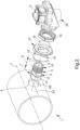
- reference numeral 1 globally denotes a fixing system for valves for cleaning industrial filters.
- the fixing system 1 can be used to attach a valve device V with which a filtering element to be cleaned is associable, not shown in detail in the figures.
- the valve device V of a type known to the technician in the field, adjusts the flow of compressed gas towards the filtering element and is used for the controlled injection of a pulse of compressed air thereon.
- the fixing system 1 comprises at least one tank 2 for the storage of a compressed gas.
- the compressed gas is compressed air.
- the tank 2 comprises an inner surface 3 and an outer surface 4.
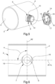
- the tank 2 is provided with at least one outlet opening 5 for the compressed gas. Specifically, the tank 2 comprises only one outlet opening 5 for each valve device V.
- the outlet opening 5 has an elongated conformation along at least a first axis A1.
- elongated conformation along at least an axis means a shape that is not circular, curvilinear or even polygonal, wherein the perimeter points are arranged at different distances from the center. In this sense, therefore, the outlet opening 5 may have, e.g., an oval, rectangular, and even square conformation.
- the tank 2 has a tubular conformation developing along a relevant longitudinal axis L and, in accordance with a preferred embodiment, the first axis A1 is substantially parallel to the longitudinal axis L. It cannot, however, be ruled out that the first axis A1 may be transverse to the longitudinal axis L of the tank 2.
- the outlet opening 5 has a substantially symmetrical conformation with respect to a plane orthogonal to the first axis A1.
- the outlet opening 5 has a substantially ellipsoidal conformation, where the major axis of the ellipse coincides with the first axis A1.
- the fixing system 1 also comprises at least one fitting body 6 developing along an axis of development S.
- the fitting body 6 is partly insertable into the tank 2 through the outlet opening 5 and is connectable to a valve device V for cleaning industrial filters.
- the fitting body 6 is provided with:
- the inlet port 8 and the outlet port 11 are aligned with each other along the axis of development S.
- the insertion portion 7 has, in turn, an elongated conformation along at least a second axis A2 substantially perpendicular to the axis of development S.
- the insertion portion 7 also has a non-circular, curvilinear, or even polygonal shape wherein the perimeter points are arranged at different distances from the center of the same.
- the insertion portion 7 can also have, e.g., an oval, rectangular and even square shape.
- the insertion portion 7 has a substantially ellipsoidal conformation, where the major axis of the ellipse coincides with the second axis A2.
- the insertion portion 7 has a conformation which is substantially complementary to the outlet opening 5.
- the central portion 9 and the threaded portion 10, on the other hand, have a circular cross-section. Furthermore, with reference to the embodiment shown in the figures, at least the central portion 9 has a diameter substantially equal to the minor axis of the ellipse defined by the insertion portion 7.
- the fitting body 6 is symmetrical with respect to at least one median plane which is orthogonal to the second axis A2 and running through the axis of development S.
- the fitting body 6 is positionable with respect to the tank 2 between a free position and a constrained position.
- the second axis A2 is substantially parallel to the first axis A1 and the fitting body 6 is free to move through the outlet opening 5 along a direction of sliding D substantially parallel to the axis of development S.
- the fitting body 6 is insertable into/extractable from the tank 2 through the outlet opening 5.
- the insertion portion 7 In the constrained position, however, the insertion portion 7 is within the tank 2, the fitting body 6 is rotated around the axis of development S by a predefined angle of rotation ⁇ and the second axis A2 is transverse to the first axis A1. Specifically, in the constrained position, the fitting body 6 is rotated around the axis of development S by an angle of rotation ⁇ substantially equal to 90° and, consequently, the second axis A2 is substantially orthogonal to the first axis A1. In such a position, moreover, the insertion portion 7 operates in conjunction with the tank 2 so as to prevent the fitting body 6 from being extracted from the tank. In the constrained position, therefore, the fitting body 6 is anchored to the tank 2. Conveniently, the insertion portion 7 comprises at least one stopping surface 12 adapted, in the constrained position, to contact the inner surface 3 of the tank 2. The stopping surface 12 prevents the fitting body 6 from sliding outwards from the tank 2, in the constrained position.
- the stopping surface 12 has a conformation which is substantially complementary to the inner surface 3 and is configured, in the constrained position, to adhere to the inner surface itself.
- the stopping surface 12 has a convex conformation.
- the stopping surface 12 allows optimal adhesion of the insertion portion 7 to the tank 2 and enables better distribution of the forces during use.
- the insertion portion 7 comprises a pair of stopping surfaces 12, arranged on opposite sides from the central portion 9.
- the fitting body 6 also comprises a central portion 9, placed between the insertion portion 7 and the threaded portion 10.
- the central portion 9 is provided with retaining means 13 adapted to retain the fitting body 6 to the tank 2.
- the insertion portion 7 and the retaining means 13 are configured to operate in conjunction with the tank 2 to prevent the fitting body 6 from moving along the direction of sliding D in both ways.
- the retaining means 13 prevent it from dropping within the tank itself.
- the retaining means 13 comprise at least one pair of retaining elements 13 protruding from the central portion 9 wherein, in the constrained position, the retaining elements 13 are adapted to contact the outer surface 4.
- the retaining elements 13 prevent the fitting body 6 from sliding towards the inside of the tank 2 in the constrained position.
- the retaining elements 13 are defined on opposite sides to the central portion 9 and are aligned with each other along a direction substantially parallel to the second axis A2.
- the fixing system 1 then comprises at least one flange body 14 which can be installed around the fitting body 6, with the latter in the constrained position, and provided with securing means 16 adapted to prevent the fitting body 6 from rotating around the axis of development S.
- the flange body 14 thus prevents the fitting body 6 from rotating and arranging itself in the free position, thus preventing it from being accidentally extracted from the tank 2 during both assembly and use.
- the securing means 16 also prevent the fitting body 6 from carrying out a shifting movement parallel to the first axis A1.
- the special arrangement of the insertion portion 7 with respect to the tank 2 causes the outlet opening 5 to define, with the fitting body 6, at least one pair of gaps 15.
- the securing means 16 conveniently comprise at least one pair of securing elements 16, each adapted to fit to size into a respective gap 15.
- the number of gaps 15 may be of different types and, consequently, the number of securing elements 16 as well.
- the flange body 14 comprises a contact surface 17 having a substantially complementary conformation to the outer surface 4 and configured to adhere to the outer surface itself.
- the contact surface 17 has a concave development.
- the securing elements 16 are associated with the contact surface 17. In detail, the securing elements 16 protrude from the contact surface 17.
- the fixing system 1 also comprises sealing means 18 positioned between at least the flange body 14 and the tank 2.
- the sealing means 18 comprise at least one seal of the type of an O-ring.
- the fixing system 1 may also comprise a fixing body 19 screwable onto part of the threaded portion 10 and adapted to attach the flange body 14 to the tank 2.
- the fixing body 19 has the function of tightening the flange body 14 on the tank 2, thus preventing it from accidentally slipping off the gaps 15.
- the fixing body 19 has the function of firmly fixing the whole fixing system 1 prior to the connection with the valve device V.
- the fixing system 1 can be without the fixing body 19 and, in that case, the valve device V is further configured to fix the flange body 14 to the tank 2.
- the fixing system 1 also comprises sealing means 18 positioned between the fixing body 19 and the flange body 14.
- the present invention also relates to a valve system 20 for cleaning industrial filters.
- the valve system 20 comprises at least one fixing system 1 according to one or more of the previously described embodiments and a valve device V for cleaning industrial filters, screwed onto the threaded portion 10.
- the described invention achieves the intended objects, and in particular, the fact is emphasized that the fixing system according to the invention for valves for cleaning industrial filters allows simplifying the assembly procedure to the tank of compressed air, thus significantly reducing the overall manufacturing time and cost.
- this fixing system allows significantly reducing the amount of machining operation required on the tank for valve installation, as well as the overall materials used, thus leading to significant energy and raw material savings and avoiding nondestructive testing on the attachment welds as required by the directives/regulations for tanks under pressure.
- the fixing system involves only the assembly of the relevant components and does not require any further complex machining operations on the tank itself.
- this fixing system makes it possible to minimize ovality so as not to impair proper operation, while avoiding the use of internal reinforcements.
- this fixing system provides only one outlet opening, of minimum size, for each valve device.
Landscapes
- Chemical & Material Sciences (AREA)
- Chemical Kinetics & Catalysis (AREA)
- Engineering & Computer Science (AREA)
- Mechanical Engineering (AREA)
- General Engineering & Computer Science (AREA)
- Physics & Mathematics (AREA)
- Geometry (AREA)
- Filling Or Discharging Of Gas Storage Vessels (AREA)
Applications Claiming Priority (1)
| Application Number | Priority Date | Filing Date | Title |
|---|---|---|---|
| IT102023000015567A IT202300015567A1 (it) | 2023-07-25 | 2023-07-25 | Sistema di fissaggio per valvole per la pulizia di filtri industriali |
Publications (2)
| Publication Number | Publication Date |
|---|---|
| EP4497489A1 true EP4497489A1 (de) | 2025-01-29 |
| EP4497489B1 EP4497489B1 (de) | 2026-04-15 |
Family
ID=88291356
Family Applications (1)
| Application Number | Title | Priority Date | Filing Date |
|---|---|---|---|
| EP24190048.9A Active EP4497489B1 (de) | 2023-07-25 | 2024-07-22 | Befestigungssystem für ventile zur reinigung von industriefiltern |
Country Status (3)
| Country | Link |
|---|---|
| EP (1) | EP4497489B1 (de) |
| CN (1) | CN118836371A (de) |
| IT (1) | IT202300015567A1 (de) |
Citations (5)
| Publication number | Priority date | Publication date | Assignee | Title |
|---|---|---|---|---|
| US3757497A (en) * | 1972-03-16 | 1973-09-11 | Slick Corp | Control valve for pulse jet type filter apparatus |
| US20050210842A1 (en) * | 2001-12-20 | 2005-09-29 | Goyen Controls Co. Pty. Ltd. | Reverse pulse cleaning of filter elements |
| EP2390539A1 (de) * | 2010-05-27 | 2011-11-30 | Aurelio Messina | Ventil und Reinigungssystem für Entstauber |
| EP3753623A1 (de) * | 2019-06-19 | 2020-12-23 | Trimec S.r.l. | Ventilvorrichtung zur reinigung industrieller filter |
| IT202200000980A1 (it) * | 2022-01-21 | 2022-04-21 | Gaetano Armenise | Valvola a impulso per la pulizia di filtri industriali |
-
2023
- 2023-07-25 IT IT102023000015567A patent/IT202300015567A1/it unknown
-
2024
- 2024-07-22 EP EP24190048.9A patent/EP4497489B1/de active Active
- 2024-07-22 CN CN202410982294.6A patent/CN118836371A/zh active Pending
Patent Citations (5)
| Publication number | Priority date | Publication date | Assignee | Title |
|---|---|---|---|---|
| US3757497A (en) * | 1972-03-16 | 1973-09-11 | Slick Corp | Control valve for pulse jet type filter apparatus |
| US20050210842A1 (en) * | 2001-12-20 | 2005-09-29 | Goyen Controls Co. Pty. Ltd. | Reverse pulse cleaning of filter elements |
| EP2390539A1 (de) * | 2010-05-27 | 2011-11-30 | Aurelio Messina | Ventil und Reinigungssystem für Entstauber |
| EP3753623A1 (de) * | 2019-06-19 | 2020-12-23 | Trimec S.r.l. | Ventilvorrichtung zur reinigung industrieller filter |
| IT202200000980A1 (it) * | 2022-01-21 | 2022-04-21 | Gaetano Armenise | Valvola a impulso per la pulizia di filtri industriali |
Also Published As
| Publication number | Publication date |
|---|---|
| EP4497489B1 (de) | 2026-04-15 |
| IT202300015567A1 (it) | 2025-01-25 |
| CN118836371A (zh) | 2024-10-25 |
Similar Documents
| Publication | Publication Date | Title |
|---|---|---|
| US3488928A (en) | Dual filter | |
| US5807483A (en) | Snap latch filter ring for a fuel injector | |
| US11969675B2 (en) | Inline-type strainer | |
| RU2010112644A (ru) | Устройства и способы смонтированных на водопроводном кране фильтрующих систем | |
| KR102200860B1 (ko) | 가스공급관로용 블랙파우더 필터링 장치 | |
| EP3692282B1 (de) | Auswechselbare ventilsteckerspitze | |
| CN100482313C (zh) | 滤芯的反向脉冲清洗 | |
| EP4497489A1 (de) | Befestigungssystem für ventile zur reinigung von industriefiltern | |
| KR20040106213A (ko) | 상수도용 스트레이너 장치 | |
| JP4272907B2 (ja) | ストレーナ | |
| KR200194074Y1 (ko) | 파이프 라인 스트레이너의 이물질 확인장치 | |
| EP1131576B1 (de) | Vorrichtung zur reinigung eines filters | |
| US20070034560A1 (en) | Drain valve alignment system for filter assembly | |
| US6149703A (en) | Fuel system filtering apparatus | |
| US20240149200A1 (en) | Pulse filter with integral support | |
| EP2436966B1 (de) | Verstärkungsvorrichtung für Sicherheitsbehälter mit Druckgas in einem Industriefilterreinigungssystem | |
| AU2008234975B2 (en) | Reverse pulse cleaning of filter elements | |
| US7294160B2 (en) | Air cleaner | |
| CN210159277U (zh) | 一种滤水装置及滤芯固定装置 | |
| RU168718U1 (ru) | Корпус фильтра для вертикально расположенной магистрали | |
| US20200298159A1 (en) | Gas filtration apparatus | |
| KR200355947Y1 (ko) | 상수도용 스트레이너 장치 | |
| KR20000005527U (ko) | 가스메터기의 여과장치 |
Legal Events
| Date | Code | Title | Description |
|---|---|---|---|
| PUAI | Public reference made under article 153(3) epc to a published international application that has entered the european phase |
Free format text: ORIGINAL CODE: 0009012 |
|
| STAA | Information on the status of an ep patent application or granted ep patent |
Free format text: STATUS: THE APPLICATION HAS BEEN PUBLISHED |
|
| AK | Designated contracting states |
Kind code of ref document: A1 Designated state(s): AL AT BE BG CH CY CZ DE DK EE ES FI FR GB GR HR HU IE IS IT LI LT LU LV MC ME MK MT NL NO PL PT RO RS SE SI SK SM TR |
|
| STAA | Information on the status of an ep patent application or granted ep patent |
Free format text: STATUS: REQUEST FOR EXAMINATION WAS MADE |
|
| 17P | Request for examination filed |
Effective date: 20250725 |
|
| GRAP | Despatch of communication of intention to grant a patent |
Free format text: ORIGINAL CODE: EPIDOSNIGR1 |
|
| STAA | Information on the status of an ep patent application or granted ep patent |
Free format text: STATUS: GRANT OF PATENT IS INTENDED |
|
| INTG | Intention to grant announced |
Effective date: 20251117 |
|
| GRAS | Grant fee paid |
Free format text: ORIGINAL CODE: EPIDOSNIGR3 |
|
| GRAA | (expected) grant |
Free format text: ORIGINAL CODE: 0009210 |
|
| STAA | Information on the status of an ep patent application or granted ep patent |
Free format text: STATUS: THE PATENT HAS BEEN GRANTED |
|
| AK | Designated contracting states |
Kind code of ref document: B1 Designated state(s): AL AT BE BG CH CY CZ DE DK EE ES FI FR GB GR HR HU IE IS IT LI LT LU LV MC ME MK MT NL NO PL PT RO RS SE SI SK SM TR |
|
| REG | Reference to a national code |
Ref country code: CH Ref legal event code: F10 Free format text: ST27 STATUS EVENT CODE: U-0-0-F10-F00 (AS PROVIDED BY THE NATIONAL OFFICE) Effective date: 20260415 |