EP4497459A1 - Vorgefüllte spritze mit nadelschutz - Google Patents
Vorgefüllte spritze mit nadelschutz Download PDFInfo
- Publication number
- EP4497459A1 EP4497459A1 EP23773431.4A EP23773431A EP4497459A1 EP 4497459 A1 EP4497459 A1 EP 4497459A1 EP 23773431 A EP23773431 A EP 23773431A EP 4497459 A1 EP4497459 A1 EP 4497459A1
- Authority
- EP
- European Patent Office
- Prior art keywords
- needle
- cantilever
- main body
- mounting member
- shielded
- Prior art date
- Legal status (The legal status is an assumption and is not a legal conclusion. Google has not performed a legal analysis and makes no representation as to the accuracy of the status listed.)
- Pending
Links
Images
Classifications
-
- A—HUMAN NECESSITIES
- A61—MEDICAL OR VETERINARY SCIENCE; HYGIENE
- A61M—DEVICES FOR INTRODUCING MEDIA INTO, OR ONTO, THE BODY; DEVICES FOR TRANSDUCING BODY MEDIA OR FOR TAKING MEDIA FROM THE BODY; DEVICES FOR PRODUCING OR ENDING SLEEP OR STUPOR
- A61M5/00—Devices for bringing media into the body in a subcutaneous, intra-vascular or intramuscular way; Accessories therefor, e.g. filling or cleaning devices, arm rests
- A61M5/178—Syringes
- A61M5/31—Details
- A61M5/32—Needles; Details of needles pertaining to their connection with syringe or hub; Accessories for bringing the needle into, or holding the needle on, the body; Devices for protection of needles
- A61M5/3205—Apparatus for removing or disposing of used needles or syringes, e.g. containers; Means for protection against accidental injuries from used needles
- A61M5/321—Means for protection against accidental injuries by used needles
- A61M5/3243—Means for protection against accidental injuries by used needles being axially-extensible, e.g. protective sleeves coaxially slidable on the syringe barrel
- A61M5/3245—Constructional features thereof, e.g. to improve manipulation or functioning
-
- A—HUMAN NECESSITIES
- A61—MEDICAL OR VETERINARY SCIENCE; HYGIENE
- A61M—DEVICES FOR INTRODUCING MEDIA INTO, OR ONTO, THE BODY; DEVICES FOR TRANSDUCING BODY MEDIA OR FOR TAKING MEDIA FROM THE BODY; DEVICES FOR PRODUCING OR ENDING SLEEP OR STUPOR
- A61M5/00—Devices for bringing media into the body in a subcutaneous, intra-vascular or intramuscular way; Accessories therefor, e.g. filling or cleaning devices, arm rests
- A61M5/178—Syringes
- A61M5/31—Details
- A61M5/32—Needles; Details of needles pertaining to their connection with syringe or hub; Accessories for bringing the needle into, or holding the needle on, the body; Devices for protection of needles
- A61M5/3202—Devices for protection of the needle before use, e.g. caps
-
- A—HUMAN NECESSITIES
- A61—MEDICAL OR VETERINARY SCIENCE; HYGIENE
- A61M—DEVICES FOR INTRODUCING MEDIA INTO, OR ONTO, THE BODY; DEVICES FOR TRANSDUCING BODY MEDIA OR FOR TAKING MEDIA FROM THE BODY; DEVICES FOR PRODUCING OR ENDING SLEEP OR STUPOR
- A61M5/00—Devices for bringing media into the body in a subcutaneous, intra-vascular or intramuscular way; Accessories therefor, e.g. filling or cleaning devices, arm rests
- A61M5/178—Syringes
- A61M5/31—Details
- A61M5/32—Needles; Details of needles pertaining to their connection with syringe or hub; Accessories for bringing the needle into, or holding the needle on, the body; Devices for protection of needles
- A61M5/3205—Apparatus for removing or disposing of used needles or syringes, e.g. containers; Means for protection against accidental injuries from used needles
- A61M5/321—Means for protection against accidental injuries by used needles
- A61M5/3213—Caps placed axially onto the needle, e.g. equipped with finger protection guards
-
- A—HUMAN NECESSITIES
- A61—MEDICAL OR VETERINARY SCIENCE; HYGIENE
- A61M—DEVICES FOR INTRODUCING MEDIA INTO, OR ONTO, THE BODY; DEVICES FOR TRANSDUCING BODY MEDIA OR FOR TAKING MEDIA FROM THE BODY; DEVICES FOR PRODUCING OR ENDING SLEEP OR STUPOR
- A61M5/00—Devices for bringing media into the body in a subcutaneous, intra-vascular or intramuscular way; Accessories therefor, e.g. filling or cleaning devices, arm rests
- A61M5/178—Syringes
- A61M5/31—Details
- A61M5/32—Needles; Details of needles pertaining to their connection with syringe or hub; Accessories for bringing the needle into, or holding the needle on, the body; Devices for protection of needles
- A61M5/3205—Apparatus for removing or disposing of used needles or syringes, e.g. containers; Means for protection against accidental injuries from used needles
- A61M5/321—Means for protection against accidental injuries by used needles
- A61M5/3243—Means for protection against accidental injuries by used needles being axially-extensible, e.g. protective sleeves coaxially slidable on the syringe barrel
- A61M5/3245—Constructional features thereof, e.g. to improve manipulation or functioning
- A61M2005/3247—Means to impede repositioning of protection sleeve from needle covering to needle uncovering position
Definitions
- the present disclosure belongs to the technical field of prefilled syringes, and particularly relates to a needle-shielded prefilled syringe.
- a prefilled syringe is a novel medicine packaging form, and may be understood as "an injectable medicine package" from another perspective. Since the prefilled syringe is also a type of syringe, the risk of stabbing people when a syringe needle is discarded after use also exists. Therefore, in order to solve the problem, a device for destroying a needle before the needle is discarded is available on the market.
- Chinese Utility Model Patent Patent No. CN210936412U, published on July 7, 2020 has disclosed a needle shearing device of an integrated syringe.
- the device comprises a first shearing member, wherein a first cavity extending in an axial direction of the first shearing member is defined in the first shearing member, one end of the first cavity is open, the first cavity can accommodate a syringe needle and allow the syringe to penetrate through, a first shearing opening communicated with the first cavity is formed in the other end of the first shearing member, and the needle and a connecting portion can penetrate through the first shearing opening; a first blade, wherein the first blade is arranged at the first shearing opening; and a second shearing member, wherein a second cavity extending in an axial direction of the second shearing member is defined in the second shearing member, one end of the second cavity is open, the other end of the second cavity sleeves the other end of the first shearing member, a driving portion is arranged in the second shearing member, the second shearing member can rotate around an axis thereof to drive the connecting portion by the driving portion to abut against the first blade
- shearing device has the following defects: firstly, injection work in hospitals is huge, and even a nurse needs to visit each ward to complete an injection task, it is very inappropriate to require the nurse to carry the shearing device, and the nurse cannot ensure that he/she will remember to carry the shearing device at any time; secondly, the needle may fly out in the shearing process, resulting in loss of the needle and even direct injuries to other people; and thirdly, the sheared needle still needs to be discarded, although the volume of medical wastes can be greatly reduced and centralized treatment can be done, the problem of needle exposure when the needle is discarded is not fundamentally solved, and centralized treatment is also time-consuming and laborious.
- the present disclosure aims to provide a needle-shielded prefilled syringe.
- a needle By means of a syringe barrel, a needle, a needle mounting member, a shield unit and a needle guard unit, the technical effect that the needle is encased, and therefore the syringe is prevented from stabbing other people in the discarding process is achieved.
- a needle-shielded prefilled syringe includes a syringe barrel and a needle, and further includes a needle mounting member, a shield unit and a needle guard unit, wherein
- the shield unit further includes a rear locking element on the shield main body, wherein a proximal end of the rear locking element axially jacks up a distal end of a maximum outer diameter position of the needle mounting member.
- the shield unit further includes wide stopping hooks, wherein distal ends of the wide stopping hooks are connected with a proximal end of the shield main body, and proximal ends of the wide stopping hooks engage in the groove.
- the shield unit further includes cantilever members and cantilever openings, wherein
- the cantilever openings extend toward distal ends to part of the shield main body.
- the shield unit further includes narrow stopping hooks, wherein
- the wide stopping hooks are symmetrically arranged.
- the narrow stopping hooks are symmetrically arranged.
- the cantilever members include cantilever elastic members and cantilever locking elements, wherein
- the cantilever members further include proximal end chamfer structures, wherein the proximal end chamfer structures are arranged at the proximal ends of the cantilever locking elements, and when the shield main body is opened, the cantilever locking elements pass over the maximum outer diameter position of the needle mounting member.
- the cantilever members further include distal end chamfer structures, wherein the distal end chambers are arranged at the distal ends of the cantilever locking elements, and when the shield main body is closed, the cantilever locking elements pass over the maximum outer diameter position of the needle mounting member.
- the needle mounting member includes a flange member, wherein when the shield main body is closed, distal ends of the flange member engage with the cantilever locking elements, and proximal ends of the flange member engage with the wide stopping hooks and the narrow stopping hooks.
- the needle mounting member includes flange chambers, wherein the flange chambers are arranged at distal ends of a flange member, and when the shield main body is opened, the cantilever locking elements pass over the flange member.
- Components of the needle-shielded prefilled syringe further include a sealing stopper and a push rod inserted into the sealing stopper.
- a mounting method of the components of the needle-shielded prefilled syringe includes the following steps:
- a medicine filling method of the components of the needle-shielded prefilled syringe includes the following steps:
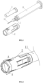
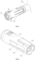
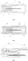
- the reference signs denote the following components: syringe barrel 11, needle 12, needle mounting member 1, shield unit 2, needle protector unit 3, flange member 101, flange chamfer 102, shield main body 201, wide stopping hook 202, cantilever member 203, cantilever opening 204, narrow stopping hook 205, cantilever elastic member 203a, cantilever locking element 203b, proximal end chamfer structure 203c, and distal end chamfer structure 203d.
- a needle-shielded prefilled syringe includes a syringe barrel 11 and a needle 12, and further includes a needle mounting member 1, a shield unit 2 and a needle protector unit 3, wherein
- a syringe device commonly used in the prior art is formed by the syringe barrel 11 and the needle 12, no push rod is arranged in the syringe barrel 11 in order to conveniently pre-fill medicines, and a downstream manufacturer can voluntarily add an appropriate push rod according to the specification of the syringe barrel 11 after medicine filling, so as to ensure sealing performance; and the shield unit 2 is overall firstly connected to the needle protector unit 3 in a sleeving manner, then the needle 12 is encased with the shield unit and the needle protector unit 3 jointly in the mounting process, and part of the shield unit 2 is connected to the needle mounting member 1 in a sleeving manner.
- the shield main body 201 and the front locking element are main components of the shield unit 2, the shield main body 201 is arranged on one side of the distal end of the overall shield unit 2, the front locking element is arranged on one side of the proximal end of the overall shield unit 2, and a minimum inner diameter of the front locking element is less than maximum outer diameters of the needle mounting member 1 and the syringe barrel 11, such that the shield main body 201 may stopping at a position where the needle 12 is encased under the engaging action of the front locking element and the groove in the fourth step, thereby achieving protection.
- the minimum inner diameter of the front locking element may be greater than the maximum outer diameter of the syringe barrel 11 by expanding the front locking element, such that the shield main body 201 slides toward the proximal end in the first step, thereby releasing the encasing effect on the needle 12 before injection.
- the shield unit 2 further includes a rear locking element on the shield main body 201, wherein a proximal end of the rear locking element axially jacks up a distal end of the maximum outer diameter position of the needle mounting member 1.
- the groove is a feature naturally formed by the maximum outer diameter position of the needle mounting member 1 and the syringe barrel 11, when the front locking element engages in the groove, a distal end of the front locking element will axially jack up a proximal end of the maximum outer diameter position of the needle mounting member 1, and meanwhile, the proximal end of the rear locking element axially jacks up the distal end of the maximum outer diameter position of the needle mounting member 1, such that the maximum outer diameter position of the needle mounting member 1 is clamped through the cooperation between the front locking element and the rear locking element, and the shield main body 201 is firmly fixed in the fourth step accordingly without merely relying on acting force generated when the front locking element engages in the groove.
- the disengagement of the shield main body from the maximum outer diameter position of the needle mounting member 1 may be done by manually expanding the rear locking element in order to smoothly push the shield main body 201, such that the shield main body 201 is smoothly pushed.
- the needle protector unit 3 will radially jack up the rear locking element to disengage the rear locking element from the maximum outer diameter position of the needle mounting member 1 accordingly.
- the advantages of the above arrangement are that when the needle protector unit 3 is in place, the shield main body 201 may be pushed merely through push force without manual expansion, whereas in the fourth step, the needle protector unit 3 has been taken down, as a result, when the rear locking element engages with the maximum outer diameter position of the needle mounting member 1, the position of the shield main body 201 cannot be adjusted merely through the push force, thereby achieving protection on the needle C.
- the shield unit 2 further includes wide stopping hooks 202, wherein distal ends of the wide stopping hooks 202 are connected with the proximal end of the shield main body 201, and proximal ends of the wide stopping hooks 202 engage in the groove.
- the wide stopping hooks 202 are one representation of the front locking element, engaging blocks extending radially are arranged at proximal ends of the wide stopping hooks and used for engaging in the groove, that is, the engaging blocks axially jack up an end face of the proximal end of the maximum outer diameter position of the needle mounting member 1, the wide stopping hooks 202 are elastic, which may expand in inner diameters thereof through bending, such that the wide stopping hooks pass over the groove to release the engaging state.
- the shield unit 2 further includes cantilever members 203 and cantilever openings 204, wherein
- the cantilever members 203 are one of representations of the rear locking element, the cantilever openings 204 are adjacent to the distal ends of the wide stopping hooks 202, and the cantilever members 203 are arranged on inner side faces of distal ends of the cantilever openings 204 and extend to proximal ends of the cantilever openings, such that a clamping component is formed by the proximal ends of the cantilever openings 204 and the proximal ends of the wide stopping hooks 202 and used for clamping the maximum outer diameter position of the needle mounting member 1 to achieve engaging.
- the cantilever members 203 are mounted by arranging the cantilever openings 204, such that the cantilever members 203 and the wide stopping hooks 202 are integrated; and actually, during preparation, the cantilever members 203 are integrally prepared in the wide stopping hooks 202, such that the cantilever members 203 cannot warp up.
- the advantages of the above arrangement are that during injection, a nurse will grasp the shield unit 2 at a gesture similar to holding a pencil, use comfort for the nurse is greatly improved due to such corner-free design, and use experience is better compared with that of other products with protruding cantilever members on the market.
- the cantilever openings 204 extend toward the distal ends to part of the shield main body 201.
- internal spaces of the cantilever openings are larger after the cantilever openings 204 extend, such that the cantilever members 203 with larger radial lengths may be mounted; and actually, a movement range of radial expansion of the cantilever members 203 is improved, such that the cantilever members can more easily pass over the maximum outer diameter position of the needle mounting member 1 when the shield main body 201 is opened.
- the shield unit 2 further includes narrow stopping hooks 205, wherein
- the narrow stopping hooks 205 have the same actual functions as the wide stopping hooks 202, the difference is that no cantilever members 203 are mounted on the narrow stopping hooks 205, the narrow stopping hooks only have the effect of limiting the shield main body 201 from radially moving toward the distal end of the shield main body, however, a spare position between the wide stopping hooks 202 is fully utilized due to such design.
- the two wide stopping hooks 202 are usually arranged at the proximal end of the shield main body 201, balance force may be provided when the narrow stopping hooks 205 are arranged between the wide stopping hooks 202, that is, the shield main body 201 is prevented from shaking when the maximum outer diameter position of the needle mounting member 1 is clamped by the wide stopping hooks 202 and the cantilever members 203.
- the wide stopping hooks 202 are symmetrically arranged.
- the narrow stopping hooks 205 are symmetrically arranged.
- the wide stopping hooks 202 and the narrow stopping hooks 205 are respectively and symmetrically designed, on one hand, the shield unit 2 is more attractive, and on the other hand, engaging force is kept balanced, such that shaking of the shield main body 201 is relieved.
- the cantilever members 203 include cantilever elastic members 203a and cantilever locking elements 203b, wherein
- each of the cantilever members 203 consists of two parts, the first part is the cantilever elastic member 203a arranged on the cantilever opening 204 and radially bent toward the shield main body 201, and the cantilever locking element 203b is arranged on a tail end face of the cantilever elastic member 203a, such that an end face of the cantilever locking element 203b can abut against a distal end face of the maximum outer diameter position of the needle mounting member 1 and be used for jacking up the distal end face of the maximum outer diameter position of the needle mounting member 1 during closing and applying a friction force on a surface of a syringe main body A during opening, thus achieving a restraining effect.
- the cantilever members 203 further include proximal end chamfer structures 203c, wherein the proximal end chamfer structures 203c are arranged at the proximal ends of the cantilever locking elements 203b, and when the shield main body 201 is opened, the cantilever locking elements 203b pass over the maximum outer diameter position of the needle mounting member 1.
- the proximal end chamfer structures 203c axially jack up the distal end face of the maximum outer diameter position of the needle mounting member 1, and radial force will be generated to drive the cantilever elastic members 203a to radially expand to pass over the maximum outer diameter position of the needle mounting member 1, such that the shield main body 201 continues to axially move.
- the cantilever members 203 further include distal end chamfer structures 203d, wherein the distal end chambers 203d are arranged at the distal ends of the cantilever locking elements 203b, and when the shield main body 201 is closed, the cantilever locking elements 203b pass over the maximum outer diameter position of the needle mounting member 1.
- the distal end chamfer structures 203d axially jack up the proximal end face of the maximum outer diameter position of the needle mounting member 1, and the cantilever elastic members 203a are driven to radially expand to pass over the maximum outer diameter position of the needle mounting member 1, such that the cantilever locking elements 203b engage with the distal end of the maximum outer diameter position of the needle mounting member 1.
- the needle mounting member 1 includes a flange member 101, wherein when the shield main body 201 is closed, distal ends of the flange member 101 engage with the cantilever locking elements 203b, and proximal ends of the flange member 101 engage with the wide stopping hooks 202 and the narrow stopping hooks 205.
- the flange member 101 are one representation of the maximum outer diameter position of the needle mounting member 1, which have the effects that the distal ends thereof are jacked up by the cantilever locking elements 203b and the proximal ends thereof are jacked up by the wide stopping hooks 202 and the narrow stopping hooks 205, and the flange member and the syringe barrel 11 form an annular groove used for engaging with the engaging blocks at the proximal ends of the wide stopping hooks 202 and the narrow stopping hooks 205.
- the flange member 101 cannot disengage from the shield main body no matter how the shield main body 201 rotates.
- the needle mounting member 1 includes flange chamfers 102, wherein the flange chambers 102 are arranged at distal ends of the flange member 101, and when the shield main body 201 is opened, the cantilever locking elements 203b pass over the flange member 101.
- the flange chamfers 102 have the same chamfer structure gradients as the distal end chamfer structures 203d, such that the distal end chamfer structures 203d abut against the flange chamfers 102 in the first step, thereby improving radial expansion force of the cantilever elastic members 203a and conveniently allowing the cantilever members 203 to pass over the flange member 101.
- Components of the needle-shielded prefilled syringe further include a sealing stopper and a push rod inserted into the sealing stopper.
- an engaging groove for mounting one end of the push rod is reserved in a rear portion of the sealing stopper.
- Amounting method of the components of the needle-shielded prefilled syringe includes the following steps:
- the shield main body 2 and the needle protector unit 3 are mounted together in a more straightforward manner, making it convenient for the application in an assembly-line-type mounting process.
- a medicine filling method of the components of the needle-shielded prefilled syringe includes the following steps:
Landscapes
- Health & Medical Sciences (AREA)
- Engineering & Computer Science (AREA)
- Hematology (AREA)
- Anesthesiology (AREA)
- Biomedical Technology (AREA)
- Heart & Thoracic Surgery (AREA)
- Vascular Medicine (AREA)
- Life Sciences & Earth Sciences (AREA)
- Animal Behavior & Ethology (AREA)
- General Health & Medical Sciences (AREA)
- Public Health (AREA)
- Veterinary Medicine (AREA)
- Environmental & Geological Engineering (AREA)
- Infusion, Injection, And Reservoir Apparatuses (AREA)
Applications Claiming Priority (2)
| Application Number | Priority Date | Filing Date | Title |
|---|---|---|---|
| CN202210276597.7A CN114642792A (zh) | 2022-03-21 | 2022-03-21 | 一种针头防护式预灌封注射器 |
| PCT/CN2023/070631 WO2023179179A1 (zh) | 2022-03-21 | 2023-01-05 | 一种针头防护式预灌封注射器 |
Publications (2)
| Publication Number | Publication Date |
|---|---|
| EP4497459A1 true EP4497459A1 (de) | 2025-01-29 |
| EP4497459A4 EP4497459A4 (de) | 2026-03-18 |
Family
ID=81994864
Family Applications (1)
| Application Number | Title | Priority Date | Filing Date |
|---|---|---|---|
| EP23773431.4A Pending EP4497459A4 (de) | 2022-03-21 | 2023-01-05 | Vorgefüllte spritze mit nadelschutz |
Country Status (4)
| Country | Link |
|---|---|
| US (1) | US20250213798A1 (de) |
| EP (1) | EP4497459A4 (de) |
| CN (1) | CN114642792A (de) |
| WO (1) | WO2023179179A1 (de) |
Families Citing this family (4)
| Publication number | Priority date | Publication date | Assignee | Title |
|---|---|---|---|---|
| CN114642792A (zh) * | 2022-03-21 | 2022-06-21 | 上海新耀湃科医疗科技股份有限公司 | 一种针头防护式预灌封注射器 |
| CN114796728B (zh) * | 2022-05-07 | 2026-01-02 | 上海新耀湃科医疗科技股份有限公司 | 一种针头保护式预灌封针筒及其组件,组件的安装方法 |
| CN117180556B (zh) * | 2023-08-25 | 2024-06-14 | 上海新耀湃科医疗科技股份有限公司 | 一种防护式预灌封注射器 |
| CN117182544B (zh) * | 2023-08-25 | 2026-01-13 | 上海新耀湃科医疗科技股份有限公司 | 一种预灌封注射器的组装方法 |
Family Cites Families (19)
| Publication number | Priority date | Publication date | Assignee | Title |
|---|---|---|---|---|
| US4737144A (en) * | 1987-03-09 | 1988-04-12 | Choksi Pradip V | Syringe with selectively exposed and enveloped needle |
| US5304149A (en) * | 1992-06-12 | 1994-04-19 | Becton, Dickinson And Company | Medical device with a lockable needle shield |
| US8932264B2 (en) * | 2003-08-11 | 2015-01-13 | Becton, Dickinson And Company | Medication delivery pen assembly with needle locking safety shield |
| CN2920270Y (zh) * | 2006-06-08 | 2007-07-11 | 黄秋月 | 胰岛素注射器结构 |
| GB0621310D0 (en) * | 2006-10-27 | 2006-12-06 | Liversidge Barry P | Medical needle safety devices |
| GB201001506D0 (en) * | 2010-02-01 | 2010-03-17 | Liversidge Barry P | Medical needle safety device |
| TW201204422A (en) * | 2010-07-26 | 2012-02-01 | Wu Chen Wen | Protection device of syringe needle |
| GB201020542D0 (en) * | 2010-12-03 | 2011-01-19 | Liversidge Barry P | Medical needle safety device |
| ES2779624T3 (es) * | 2011-11-07 | 2020-08-18 | Safety Syringes Inc | Protector de aguja con activación de disparo por contacto |
| GB201222900D0 (en) * | 2012-12-19 | 2013-01-30 | Tip Top Com Ltd | Medical needle safety device |
| GB201401456D0 (en) * | 2014-01-28 | 2014-03-12 | Liversidge Barry P | Medical needle safety device |
| EP3242700B1 (de) * | 2015-01-08 | 2020-09-09 | Novo Nordisk A/S | Nadeleinheit mit arretierbarem nadelschild und injektionsvorrichtung mit solch einer nadeleinheit |
| CN210936412U (zh) | 2019-10-08 | 2020-07-07 | 首都医科大学附属北京儿童医院 | 一体式注射器的针头剪切装置 |
| CN211835651U (zh) * | 2019-12-31 | 2020-11-03 | 江苏苏云医疗器材有限公司 | 一种抽拉式防刺伤注射器 |
| CN114642792A (zh) * | 2022-03-21 | 2022-06-21 | 上海新耀湃科医疗科技股份有限公司 | 一种针头防护式预灌封注射器 |
| CN218220748U (zh) * | 2022-03-21 | 2023-01-06 | 上海新耀湃科医疗科技股份有限公司 | 一种针头防护式预灌封注射器 |
| CN218220747U (zh) * | 2022-03-21 | 2023-01-06 | 上海新耀湃科医疗科技股份有限公司 | 一种具有防护罩的预灌封注射器,及其组件 |
| CN114642793A (zh) * | 2022-03-21 | 2022-06-21 | 上海新耀湃科医疗科技股份有限公司 | 一种带有前置护罩的预灌封注射器 |
| CN114652920B (zh) * | 2022-03-21 | 2025-06-03 | 上海新耀湃科医疗科技股份有限公司 | 一种具有防护罩的预灌封注射器,及其组件,组件组装方法,和药品灌封方法 |
-
2022
- 2022-03-21 CN CN202210276597.7A patent/CN114642792A/zh active Pending
-
2023
- 2023-01-05 EP EP23773431.4A patent/EP4497459A4/de active Pending
- 2023-01-05 WO PCT/CN2023/070631 patent/WO2023179179A1/zh not_active Ceased
- 2023-01-05 US US18/849,220 patent/US20250213798A1/en active Pending
Also Published As
| Publication number | Publication date |
|---|---|
| EP4497459A4 (de) | 2026-03-18 |
| CN114642792A (zh) | 2022-06-21 |
| US20250213798A1 (en) | 2025-07-03 |
| WO2023179179A1 (zh) | 2023-09-28 |
Similar Documents
| Publication | Publication Date | Title |
|---|---|---|
| US20250213798A1 (en) | Needle-shielded prefilled syringe | |
| AU779886B2 (en) | Method of making a retracting needle syringe | |
| US4775363A (en) | Arrangement in injection syringe for use once only | |
| AU779820B2 (en) | Retracting needle syringe | |
| US6193695B1 (en) | Disposable safety syringe having a retractable needle | |
| AU720121B2 (en) | Self-retracting medical needle apparatus and methods | |
| DE69218592T2 (de) | Spritze | |
| US4692156A (en) | Disposable syringe with retractable cannula | |
| DE69428981T2 (de) | Spritze für subkutaninjektionen mit einer zurückziehbaren nadel | |
| US20160331900A1 (en) | Automatic Medication Injection Device | |
| ZA200105361B (en) | Single use syringe with breakaway plunger. | |
| DE19740259A1 (de) | Einziehbare Sicherheitseinmalspritze | |
| WO2007112470A1 (de) | Injektionsspritze | |
| CN1627970A (zh) | 用于预充注注射器的安全护罩系统 | |
| CN218220747U (zh) | 一种具有防护罩的预灌封注射器,及其组件 | |
| CN114652920A (zh) | 一种具有防护罩的预灌封注射器,及其组件,组件组装方法,和药品灌封方法 | |
| US20200405963A1 (en) | Syringe with locking mechanism | |
| EP1272240B1 (de) | Hypodermatische spritze | |
| CN1024757C (zh) | 一次性注射器 | |
| AU779896B2 (en) | Retracting needle syringe | |
| CN100448491C (zh) | 具有伸缩式针头部件的注射器 | |
| CN218220748U (zh) | 一种针头防护式预灌封注射器 | |
| KR102760533B1 (ko) | 안전 주사 바늘 조립체 | |
| CA3191774A1 (en) | Syringe with an improved needle retraction mechanism | |
| GB2234175A (en) | Mono-use syringe for hypodermic injections |
Legal Events
| Date | Code | Title | Description |
|---|---|---|---|
| STAA | Information on the status of an ep patent application or granted ep patent |
Free format text: STATUS: THE INTERNATIONAL PUBLICATION HAS BEEN MADE |
|
| PUAI | Public reference made under article 153(3) epc to a published international application that has entered the european phase |
Free format text: ORIGINAL CODE: 0009012 |
|
| STAA | Information on the status of an ep patent application or granted ep patent |
Free format text: STATUS: REQUEST FOR EXAMINATION WAS MADE |
|
| 17P | Request for examination filed |
Effective date: 20241002 |
|
| AK | Designated contracting states |
Kind code of ref document: A1 Designated state(s): AL AT BE BG CH CY CZ DE DK EE ES FI FR GB GR HR HU IE IS IT LI LT LU LV MC ME MK MT NL NO PL PT RO RS SE SI SK SM TR |
|
| DAV | Request for validation of the european patent (deleted) | ||
| DAX | Request for extension of the european patent (deleted) | ||
| A4 | Supplementary search report drawn up and despatched |
Effective date: 20260216 |
|
| RIC1 | Information provided on ipc code assigned before grant |
Ipc: A61M 5/32 20060101AFI20260210BHEP Ipc: A61M 5/178 20060101ALI20260210BHEP |