EP4496053A1 - Aging system - Google Patents
Aging system Download PDFInfo
- Publication number
- EP4496053A1 EP4496053A1 EP23898145.0A EP23898145A EP4496053A1 EP 4496053 A1 EP4496053 A1 EP 4496053A1 EP 23898145 A EP23898145 A EP 23898145A EP 4496053 A1 EP4496053 A1 EP 4496053A1
- Authority
- EP
- European Patent Office
- Prior art keywords
- coupled
- air conditioning
- aging system
- mast
- chamber
- Prior art date
- Legal status (The legal status is an assumption and is not a legal conclusion. Google has not performed a legal analysis and makes no representation as to the accuracy of the status listed.)
- Pending
Links
Images





Classifications
-
- H—ELECTRICITY
- H01—ELECTRIC ELEMENTS
- H01M—PROCESSES OR MEANS, e.g. BATTERIES, FOR THE DIRECT CONVERSION OF CHEMICAL ENERGY INTO ELECTRICAL ENERGY
- H01M10/00—Secondary cells; Manufacture thereof
- H01M10/42—Methods or arrangements for servicing or maintenance of secondary cells or secondary half-cells
- H01M10/44—Methods for charging or discharging
- H01M10/441—Methods for charging or discharging for several batteries or cells simultaneously or sequentially
-
- H—ELECTRICITY
- H01—ELECTRIC ELEMENTS
- H01M—PROCESSES OR MEANS, e.g. BATTERIES, FOR THE DIRECT CONVERSION OF CHEMICAL ENERGY INTO ELECTRICAL ENERGY
- H01M10/00—Secondary cells; Manufacture thereof
- H01M10/04—Construction or manufacture in general
-
- H—ELECTRICITY
- H01—ELECTRIC ELEMENTS
- H01M—PROCESSES OR MEANS, e.g. BATTERIES, FOR THE DIRECT CONVERSION OF CHEMICAL ENERGY INTO ELECTRICAL ENERGY
- H01M4/00—Electrodes
- H01M4/02—Electrodes composed of, or comprising, active material
- H01M4/04—Processes of manufacture in general
- H01M4/0438—Processes of manufacture in general by electrochemical processing
- H01M4/044—Activating, forming or electrochemical attack of the supporting material
- H01M4/0445—Forming after manufacture of the electrode, e.g. first charge, cycling
- H01M4/0447—Forming after manufacture of the electrode, e.g. first charge, cycling of complete cells or cells stacks
-
- B—PERFORMING OPERATIONS; TRANSPORTING
- B66—HOISTING; LIFTING; HAULING
- B66F—HOISTING, LIFTING, HAULING OR PUSHING, NOT OTHERWISE PROVIDED FOR, e.g. DEVICES WHICH APPLY A LIFTING OR PUSHING FORCE DIRECTLY TO THE SURFACE OF A LOAD
- B66F9/00—Devices for lifting or lowering bulky or heavy goods for loading or unloading purposes
- B66F9/06—Devices for lifting or lowering bulky or heavy goods for loading or unloading purposes movable, with their loads, on wheels or the like, e.g. fork-lift trucks
- B66F9/07—Floor-to-roof stacking devices, e.g. "stacker cranes", "retrievers"
-
- B—PERFORMING OPERATIONS; TRANSPORTING
- B66—HOISTING; LIFTING; HAULING
- B66F—HOISTING, LIFTING, HAULING OR PUSHING, NOT OTHERWISE PROVIDED FOR, e.g. DEVICES WHICH APPLY A LIFTING OR PUSHING FORCE DIRECTLY TO THE SURFACE OF A LOAD
- B66F9/00—Devices for lifting or lowering bulky or heavy goods for loading or unloading purposes
- B66F9/06—Devices for lifting or lowering bulky or heavy goods for loading or unloading purposes movable, with their loads, on wheels or the like, e.g. fork-lift trucks
- B66F9/075—Constructional features or details
-
- B—PERFORMING OPERATIONS; TRANSPORTING
- B66—HOISTING; LIFTING; HAULING
- B66F—HOISTING, LIFTING, HAULING OR PUSHING, NOT OTHERWISE PROVIDED FOR, e.g. DEVICES WHICH APPLY A LIFTING OR PUSHING FORCE DIRECTLY TO THE SURFACE OF A LOAD
- B66F9/00—Devices for lifting or lowering bulky or heavy goods for loading or unloading purposes
- B66F9/06—Devices for lifting or lowering bulky or heavy goods for loading or unloading purposes movable, with their loads, on wheels or the like, e.g. fork-lift trucks
- B66F9/075—Constructional features or details
- B66F9/07504—Accessories, e.g. for towing, charging, locking
-
- B—PERFORMING OPERATIONS; TRANSPORTING
- B66—HOISTING; LIFTING; HAULING
- B66F—HOISTING, LIFTING, HAULING OR PUSHING, NOT OTHERWISE PROVIDED FOR, e.g. DEVICES WHICH APPLY A LIFTING OR PUSHING FORCE DIRECTLY TO THE SURFACE OF A LOAD
- B66F9/00—Devices for lifting or lowering bulky or heavy goods for loading or unloading purposes
- B66F9/06—Devices for lifting or lowering bulky or heavy goods for loading or unloading purposes movable, with their loads, on wheels or the like, e.g. fork-lift trucks
- B66F9/075—Constructional features or details
- B66F9/08—Masts; Guides; Chains
-
- H—ELECTRICITY
- H01—ELECTRIC ELEMENTS
- H01M—PROCESSES OR MEANS, e.g. BATTERIES, FOR THE DIRECT CONVERSION OF CHEMICAL ENERGY INTO ELECTRICAL ENERGY
- H01M10/00—Secondary cells; Manufacture thereof
- H01M10/05—Accumulators with non-aqueous electrolyte
- H01M10/058—Construction or manufacture
-
- H—ELECTRICITY
- H01—ELECTRIC ELEMENTS
- H01M—PROCESSES OR MEANS, e.g. BATTERIES, FOR THE DIRECT CONVERSION OF CHEMICAL ENERGY INTO ELECTRICAL ENERGY
- H01M10/00—Secondary cells; Manufacture thereof
- H01M10/42—Methods or arrangements for servicing or maintenance of secondary cells or secondary half-cells
- H01M10/44—Methods for charging or discharging
- H01M10/446—Initial charging measures
-
- H—ELECTRICITY
- H01—ELECTRIC ELEMENTS
- H01M—PROCESSES OR MEANS, e.g. BATTERIES, FOR THE DIRECT CONVERSION OF CHEMICAL ENERGY INTO ELECTRICAL ENERGY
- H01M10/00—Secondary cells; Manufacture thereof
- H01M10/60—Heating or cooling; Temperature control
- H01M10/61—Types of temperature control
- H01M10/617—Types of temperature control for achieving uniformity or desired distribution of temperature
-
- B—PERFORMING OPERATIONS; TRANSPORTING
- B65—CONVEYING; PACKING; STORING; HANDLING THIN OR FILAMENTARY MATERIAL
- B65G—TRANSPORT OR STORAGE DEVICES, e.g. CONVEYORS FOR LOADING OR TIPPING, SHOP CONVEYOR SYSTEMS OR PNEUMATIC TUBE CONVEYORS
- B65G1/00—Storing articles, individually or in orderly arrangement, in warehouses or magazines
- B65G1/02—Storage devices
- B65G1/04—Storage devices mechanical
- B65G1/0407—Storage devices mechanical using stacker cranes
-
- H—ELECTRICITY
- H01—ELECTRIC ELEMENTS
- H01M—PROCESSES OR MEANS, e.g. BATTERIES, FOR THE DIRECT CONVERSION OF CHEMICAL ENERGY INTO ELECTRICAL ENERGY
- H01M10/00—Secondary cells; Manufacture thereof
- H01M10/05—Accumulators with non-aqueous electrolyte
- H01M10/052—Li-accumulators
- H01M10/0525—Rocking-chair batteries, i.e. batteries with lithium insertion or intercalation in both electrodes; Lithium-ion batteries
-
- Y—GENERAL TAGGING OF NEW TECHNOLOGICAL DEVELOPMENTS; GENERAL TAGGING OF CROSS-SECTIONAL TECHNOLOGIES SPANNING OVER SEVERAL SECTIONS OF THE IPC; TECHNICAL SUBJECTS COVERED BY FORMER USPC CROSS-REFERENCE ART COLLECTIONS [XRACs] AND DIGESTS
- Y02—TECHNOLOGIES OR APPLICATIONS FOR MITIGATION OR ADAPTATION AGAINST CLIMATE CHANGE
- Y02E—REDUCTION OF GREENHOUSE GAS [GHG] EMISSIONS, RELATED TO ENERGY GENERATION, TRANSMISSION OR DISTRIBUTION
- Y02E60/00—Enabling technologies; Technologies with a potential or indirect contribution to GHG emissions mitigation
- Y02E60/10—Energy storage using batteries
-
- Y—GENERAL TAGGING OF NEW TECHNOLOGICAL DEVELOPMENTS; GENERAL TAGGING OF CROSS-SECTIONAL TECHNOLOGIES SPANNING OVER SEVERAL SECTIONS OF THE IPC; TECHNICAL SUBJECTS COVERED BY FORMER USPC CROSS-REFERENCE ART COLLECTIONS [XRACs] AND DIGESTS
- Y02—TECHNOLOGIES OR APPLICATIONS FOR MITIGATION OR ADAPTATION AGAINST CLIMATE CHANGE
- Y02P—CLIMATE CHANGE MITIGATION TECHNOLOGIES IN THE PRODUCTION OR PROCESSING OF GOODS
- Y02P70/00—Climate change mitigation technologies in the production process for final industrial or consumer products
- Y02P70/50—Manufacturing or production processes characterised by the final manufactured product
Definitions
- the present invention relates to an aging system for aging a plurality of cells. More particularly, the present invention relates to an aging system that is adjustable to minimize the temperature variation of each cell during aging of a plurality of cells that is housed.
- medium or large devices such as notebook computers, portable DVDs, small PCs, electric vehicles, hybrid electric vehicles, etc. require the use of battery modules including multiple battery cells for power and capacity reasons.
- Battery modules are manufactured by assembling the battery cells and activating the batteries, where the battery cells are mounted in a predetermined jig and charged to the conditions required for activation.
- Conventional secondary batteries such as nickel-cadmium batteries and lead-acid batteries, can be used immediately after production, so charging and discharging devices were only needed for performance evaluation.
- lithium secondary batteries such as lithium-ion batteries and lithium polymer batteries, which are widely used in recent years, the performance of the battery is completed only after the battery is subjected to a predetermined charging and discharging process, i.e., the chemical process, so charging and discharging devices have become essential equipment in the production line of secondary batteries.
- the charge and discharge device performs the function of giving the secondary battery its characteristics by repeating the charging and discharging process several times so that the primary battery that has been assembled can store electrical energy.
- the supply of secondary batteries has increased in response to the rapidly increasing demand for secondary batteries, it has become necessary to efficiently control the charging and discharging devices that perform the charging and discharging functions during the production stage of secondary batteries.
- the battery cells After the battery cells have been processed in these charging and discharging devices, they are moved to the next process by a stacker crane that carries a tray for loading the battery cells.
- FIG. 1 shows a stacker crane 20 for moving a tray T and a chamber 1 in which trays T carried by the stacker crane 20 are loaded, the stacker crane 20 being equipped for horizontal movement along guide rails R located side by side at upper and lower parts, respectively, as shown in FIG. 1 , elevating the elevating unit 30, on which the trays T are seated, up and down to deliver and load the trays T to the respective ends of the chamber 1 for which they are intended, or, conversely, to retrieve the loaded trays T.
- the tray T loaded in the chamber 1 and the battery cells included in the tray T may be subjected to aging at various temperature conditions.
- the present invention provides an aging system for aging a plurality of cells, including: a plurality of chambers comprising multiple levels, each of the levels housing a cell; and a crane unit provided adjacent to the chamber, for transporting and delivering cells to each level of the chamber; and the crane unit includes: an upper frame; a lower frame; a pair of masts connecting the upper and lower frames; and a lifting unit coupled to the mast so as to be lifted up and down by being guided by mast, wherein the crane unit further includes at least one air conditioning fan that blows wind to circulate air so that the temperature distribution of each cell housed in the chamber is uniform.
- the air conditioning fan is provided on the mast to blow wind in a horizontal direction.
- the single mast is coupled to a plurality of air conditioning fans, and the air conditioning fan may be provided at predetermined distance spaced along the mast.
- the lifting unit includes: a base plate; and a support wall coupled to both sides of the base plate and slidably coupled to the mast, and the air conditioning fan may be provided by being coupled to both ends of the support wall.
- the air conditioning fan may be coupled to a pair of support walls coupled to both sides of the base plate.
- the air conditioning fan may be coupled to the upper frame.
- the air conditioning fan may be coupled to the upper frame so as to be perpendicular to the extending direction of the mast to blow wind in an upward and downward direction.
- the air conditioning fan may be coupled to the upper frame so as to be horizontal to the extending direction of the mast to blow wind in a horizontal direction.
- the crane unit may be horizontally movable to transport and deliver cells to the respective chambers.
- Between the neighboring chambers includes a guide rail extending therebetween to pass between the chambers, wherein the crane unit may be slidably coupled to the guide rail.
- the chamber may further include a heating unit for applying heat to each of the cells housed therein.
- the temperature deviation between the chambers in which each cell is housed can be minimized to homogenize the performance and quality of each cell, thereby improving the efficiency and yield of the cell activation process, thereby reducing the cost of the cells.
- the present invention relates to an aging system for aging a plurality of cells, characterized in that the aging system applies an air conditioning fan 250 to a crane unit 200 that moves between each chamber 100 in which cells are housed to minimize the temperature variation of each cell during aging of the plurality of cells.
- FIGS. 2 through 7 illustrate an aging system according to a first embodiment of the present invention
- FIGS. 8 through 9 illustrate an aging system according to a second embodiment of the present invention
- FIGS. 10 through 12 illustrate an aging system according to a third embodiment of the present invention.
- the cell manufacturing process consists of electrode manufacturing, assembly, activation, and packaging/shipping.
- the activation process is a process in which cells that have passed through the assembly process are stored for a certain period of time to age, and then charged/discharged again to improve cell performance.
- This activation process can be performed through a chamber 100 comprising a plurality of levels as shown in FIG. 1 .
- One level of the chamber 100 may be seated with a plurality of trays including cells housed side-by-side in a transverse direction.
- the trays to be loaded into each of the chambers 100 are transferred by a crane unit 200.
- the crane unit 200 upon reaching a certain position, operates a lifting unit 240 to deliver the tray being transported to a certain level of the chamber 100.
- the tray may house a plurality of cells, each of the cells being in electrical connection with the tray.
- the chamber 100 may have a structure that is electrically connected to the tray to allow charging and discharging of each of the cells housed in the tray.
- FIG. 2 illustrates an aging system according to a first embodiment of the present invention.
- the aging system of the present invention includes a chamber 100 and a crane unit 200, as shown in FIG. 2 .
- the aging system of the present invention includes at least one or more chambers 100, each of the chambers 100 being spaced apart at predetermined distance to allow a crane unit 200 to be moved and passed between them.
- Each of the chambers 100 may include multiple levels, as shown in FIG. 2 , wherein each level may be seated with a plurality of trays including cells side by side.
- each of the chambers 100 may be installed a guide rail R, as shown, the guide rail R extending between a pair of opposing and neighboring chambers 100.
- a crane unit 200 may be guided along the guide rails R between the respective chambers 100.
- the guide rail R may be formed to be coupled to at least one of the upper and lower parts of the crane unit 200.
- the aging system of the present invention includes a pair of guide rails R coupled to both the upper and lower parts of the crane unit 200 so as to stably support and guide the crane unit 200.
- the pair of guide rails R is level with each other with respect to the up and down directions.
- the crane unit 200 is coupled to the guide rail R to be able to slide, so that it can be moved along the direction in which the guide rail R extends.
- the chamber 100 may further include a tray housed in each level and a heating unit (not shown) for applying heat to the plurality of cells included in the tray.
- the cell In order to express the above cell performance, the cell should be left for a certain period of time at a high temperature, which requires a heating unit to create a high temperature environment.
- the type of heating unit need not be particularly limited, and any device capable of delivering heat to each tray and cell via radiation can be used.
- each of the chambers 100 included in the aging system of the present invention may be closely spaced, air circulation in the area where the chambers 100 are located may be poor. This may in turn cause heat to be unevenly transferred from zone to zone, making it impossible to keep the cells in the same environment. Thus, a plurality of cells that are not aged in the same environment may exhibit significant differences in cell performance.
- the aging system of the present invention is characterized in that it controls a crane unit 200, which is a device for transporting trays containing cells to and from these chambers 100, to induce air circulation between the chambers 100 to minimize deviations in temperature in each chamber 100 or for each tray.
- a crane unit 200 which is a device for transporting trays containing cells to and from these chambers 100, to induce air circulation between the chambers 100 to minimize deviations in temperature in each chamber 100 or for each tray.
- the crane unit 200 is provided adjacent to the chamber 100 and serves to transport and deliver cells to each level of the chamber 100.
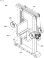
- FIG. 3 is a perspective view of a crane unit 200 according to a first embodiment of the present invention
- FIG. 4 is a simplified side view of the crane unit 200 of FIG. 3 .
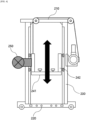
- the crane unit 200 includes an upper frame 210, a lower frame 220, a pair of masts 230 connecting the upper frame 210 and the lower frame 220, and a lifting unit 240 coupled to the mast so as to be lifted up and down by being guided by mast, as shown in FIGS. 3 and 4 .
- the upper frame 210 is coupled to a guide rail R located at an upper part of the crane unit 200 to be able to slide
- the lower frame 220 is coupled to a guide rail R located at a lower part of the crane unit 200 to be able to slide.
- the pair of masts 230 are coupled to connect two ends of the upper frame 210 and lower frame 220, respectively.
- One side of the mast 230 may be coupled with a driving device capable of driving the lifting unit 240 to be lifted.
- the lifting unit 240 serves to seat the tray including the cells, and to move the corresponding tray up and down to deliver it to each level of the chamber 100.
- the lifting unit 240 and the driving device may be connected by a wire.
- the lifting unit 240 moves upwardly, and when the wire is unwound, the lifting unit 240 moves downwardly.
- the lifting unit 240 is slidably coupled to the inner surface of a pair of masts 230 in which both sides are spaced apart by a predetermined distance.
- the lifting unit 240 may be capable of reciprocating up and down lifting movement along the mast 230, as shown in FIG. 4 .
- the inner surface of the mast 230 may include a separate lifting rail along which the lifting unit 240 slides, and the lifting unit 240 is coupled to the lifting rail included in the mast 230 to be able to slide.
- the lifting unit 240 includes a base plate 241 supporting a lower part of the tray, as shown, and a support wall 242 coupled to both sides of the base plate 241 and coupled to the mast 230, as shown, to be able to slide with respect to the mast 230.
- the support wall 242 is supported and directly coupled to the lifting rails included in the inner surface of the mast 230 and serves to support and protect both sides of the tray seated on the base plate 241.
- the crane unit 200 included in the aging system of the present invention is characterized in that it further includes at least one air conditioning fan 250, which blows wind to circulate air so that the temperature distribution of each cell housed in the chamber 100 is homogenized.
- the fan included in the air conditioning fan 250 is formed to send wind in one direction.
- the aging system according to the first embodiment of the present invention is characterized in that the air conditioning fan 250 is coupled to the support wall 242 of the crane.
- the crane unit 200 is configured with a pair of air conditioning fans 250 facing each other at either end of the support wall 242.
- Each of the pair of air conditioning fans 250 is preferably provided to blow wind in an outward direction relative to the crane unit 200.
- An air conditioning fan 250 coupled to the lifting unit 240 may blow wind while traveling up and down along the lifting unit 240, as shown in FIG. 4 .
- the crane unit 200 moves between the chambers 100 along the guide rails R, with the air conditioning fan 250 configured as described above, to blow wind into each chamber 100.
- the crane unit 200 moves in a horizontal direction along the guide rails R and blows wind into each of the chambers 100 and between the chambers 100 with the air conditioning fan 250. Furthermore, the crane unit 200 can blow wind up and down each of the chambers 100, for example from the level located at the uppermost part of the chamber 100 to the level located at the lowermost part, by lifting up and down the lifting unit 240 and the air conditioning fan 250 coupled to the lifting unit 240.
- the air conditioning fan 250 blows wind between the chambers 100 located on either side of the crane unit 200 to induce a convective circulation of air.
- the heat accumulated in a particular part can be spread to the surroundings along the circulation and, consequently, the temperature variation can be reduced between the chambers 100 included in all the zones through which the crane unit 200 travels.
- FIG. 5 is a plan view schematically illustrating a portion of the chambers 100 and crane unit 200 included in the aging system of the present invention to simplify the representation of air movement Ma by the crane unit 200 moving between the chambers 100.
- a guide rail R is formed extending between the plurality of chambers 100 arranged to face each other, and along the guide rail R the crane unit 200 is moved.
- the crane unit 200 is moved and at the same time generated wind using the air conditioning fan 250 in both directions, and air circulation Ma is carried out between each chamber 100 by the movement of the crane unit 200 and the operation of the air conditioning fan 250.
- heat that is unevenly distributed to each zone within each chamber 100 or any one chamber 100 may circulate and move to a zone of lower temperature due to the air circulation Ma.
- FIG. 6 illustrates a modified example of a crane unit 200 included in an aging system according to a first embodiment of the present invention
- FIG. 7 illustrates a side view of the crane unit 200 of FIG. 6 .
- the crane unit 200 has an air conditioning fan 250 coupled to each side of the base plate 241 as shown in FIG. 6 .
- each of the air conditioning fans 250 is coupled to a pair of support walls 242 coupled to both sides of the base plate 241. In this case, each of the air conditioning fans 250 is coupled to both ends of each of the support walls 242.
- the crane unit 200 of the structure shown in FIGS. 6 and 7 may have air conditioning fans 250 in the front and back, respectively, to more effectively circulate heat and air between each chamber 100 or each tray.
- the aging system according to the second embodiment of the present invention differs from the aging system according to the first embodiment in that the air conditioning fan 250 is fixedly installed on the mast 230, whereas in the first embodiment, the air conditioning fan 250 included in the crane unit 200 is installed on the lifting unit 240, which is lifted up and down.
- FIG. 8 illustrates an aging system according to a second embodiment of the present invention
- FIG. 9 illustrates a side view of a crane unit 200 included in the aging system according to the second embodiment.
- the single mast 230 is coupled to a plurality of air conditioning fans 250, characterized in that the air conditioning fans 250 are spaced at predetermined distance along the mast 230.
- the crane unit 200 of the aging system according to the second embodiment can induce air circulation by blowing wind at all heights even when the lifting unit 240 is not lifted.
- the air conditioning fans 250 coupled in turn along the mast 230 are preferably alternately coupled so that the wind direction of neighboring air conditioning fans 250 is opposite to each other.
- the aging system according to the third embodiment of the present invention differs from the aging system according to the first embodiment in that the air conditioning fan 250 is fixedly installed on the upper frame 210, whereas in the first embodiment, the air conditioning fan 250 included in the crane unit 200 is installed on the lifting unit 240, which is lifted up and down.
- the air conditioning fan 250 is coupled to the upper frame 210 so as to be perpendicular to the extending direction of the mast 230 to blow wind in an upward and downward direction.
- FIG. 10 is a perspective view of a crane unit 200 included in an aging system according to a third embodiment of the present invention
- FIG. 11 is a simplified side view of the crane unit 200 of FIG. 10 .
- FIG. 11 illustrates an example in which the air conditioning fan 250 is coupled to blow wind downwardly, causing air to be moved downwardly Ma by the air conditioning fans 250 and then spread to the surroundings.
- the crane unit 200 As the crane unit 200 moves horizontally around the chamber 100 along the guide rails R, it can effectively send the heat accumulated at the upper part downward, thereby reducing the up and down temperature variation within the chamber 100.
- the air conditioning fan 250 coupled to the upper frame 210 may be coupled to blow wind in a horizontal direction.
- FIG. 12 illustrates a modified example of the crane included in the aging system according to a third embodiment, wherein the air conditioning fan 250 is coupled to the upper frame 210 so as to be horizontal to the extending direction of the mast 230 to blow wind in a horizontal direction.
- the crane unit 200 can blow wind only at the upper part of each chamber 100, aiming at the upper part of the chamber 100 so that the heat accumulated in a particular zone can quickly move to the surrounding areas.
Landscapes
- Engineering & Computer Science (AREA)
- Structural Engineering (AREA)
- Transportation (AREA)
- Chemical Kinetics & Catalysis (AREA)
- Electrochemistry (AREA)
- General Chemical & Material Sciences (AREA)
- Chemical & Material Sciences (AREA)
- Manufacturing & Machinery (AREA)
- Civil Engineering (AREA)
- Life Sciences & Earth Sciences (AREA)
- Geology (AREA)
- Mechanical Engineering (AREA)
- Warehouses Or Storage Devices (AREA)
- Secondary Cells (AREA)
- Apparatus Associated With Microorganisms And Enzymes (AREA)
Abstract
Description
- The present invention relates to an aging system for aging a plurality of cells. More particularly, the present invention relates to an aging system that is adjustable to minimize the temperature variation of each cell during aging of a plurality of cells that is housed.
- This application claims the benefit of priority from
Korean Patent Application No. 10-2022-0161390, filed on November 28, 2022 - As the demand for high-performance mobile devices increases, the need to improve the performance of secondary batteries is growing rapidly.
- In particular, medium or large devices such as notebook computers, portable DVDs, small PCs, electric vehicles, hybrid electric vehicles, etc. require the use of battery modules including multiple battery cells for power and capacity reasons.
- Battery modules are manufactured by assembling the battery cells and activating the batteries, where the battery cells are mounted in a predetermined jig and charged to the conditions required for activation. Conventional secondary batteries, such as nickel-cadmium batteries and lead-acid batteries, can be used immediately after production, so charging and discharging devices were only needed for performance evaluation. However, for lithium secondary batteries, such as lithium-ion batteries and lithium polymer batteries, which are widely used in recent years, the performance of the battery is completed only after the battery is subjected to a predetermined charging and discharging process, i.e., the chemical process, so charging and discharging devices have become essential equipment in the production line of secondary batteries.
- During the production process of a secondary battery, the charge and discharge device performs the function of giving the secondary battery its characteristics by repeating the charging and discharging process several times so that the primary battery that has been assembled can store electrical energy. As the supply of secondary batteries has increased in response to the rapidly increasing demand for secondary batteries, it has become necessary to efficiently control the charging and discharging devices that perform the charging and discharging functions during the production stage of secondary batteries.
- After the battery cells have been processed in these charging and discharging devices, they are moved to the next process by a stacker crane that carries a tray for loading the battery cells.
-
FIG. 1 shows astacker crane 20 for moving a tray T and a chamber 1 in which trays T carried by thestacker crane 20 are loaded, thestacker crane 20 being equipped for horizontal movement along guide rails R located side by side at upper and lower parts, respectively, as shown inFIG. 1 , elevating theelevating unit 30, on which the trays T are seated, up and down to deliver and load the trays T to the respective ends of the chamber 1 for which they are intended, or, conversely, to retrieve the loaded trays T. - As described above, the tray T loaded in the chamber 1 and the battery cells included in the tray T may be subjected to aging at various temperature conditions.
- However, the commonly used chambers 1 have a huge size, and since each of the chambers 1 is loaded with a myriad of trays T, the problem of unequal temperatures in different zones may arise. That is, each tray T and battery cell is aged under unequal temperature conditions, resulting in the possibility of not obtaining a standardized battery cell.
-
-
Korean Patent Publication No. 10-2015-0026521 -
Korean Patent Publication No. 10-1998-0040131 - Accordingly, the present invention was invented to solve the above problems, and aims to minimize the temperature variation between the chambers in which each cell is housed during the aging process of a plurality of cells, thereby homogenizing the performance and quality of each cell.
- Other objects and advantages of the present invention will be understood from the following description, and will become more apparent from the embodiments of the present invention. It will also be readily apparent that the objects and advantages of the present invention may be realized by the means and combinations thereof disclosed in the patent claims.
- According to the present invention, the present invention provides an aging system for aging a plurality of cells, including: a plurality of chambers comprising multiple levels, each of the levels housing a cell; and a crane unit provided adjacent to the chamber, for transporting and delivering cells to each level of the chamber; and the crane unit includes: an upper frame; a lower frame; a pair of masts connecting the upper and lower frames; and a lifting unit coupled to the mast so as to be lifted up and down by being guided by mast, wherein the crane unit further includes at least one air conditioning fan that blows wind to circulate air so that the temperature distribution of each cell housed in the chamber is uniform.
- The air conditioning fan is provided on the mast to blow wind in a horizontal direction.
- The single mast is coupled to a plurality of air conditioning fans, and the air conditioning fan may be provided at predetermined distance spaced along the mast.
- The lifting unit includes: a base plate; and a support wall coupled to both sides of the base plate and slidably coupled to the mast, and the air conditioning fan may be provided by being coupled to both ends of the support wall.
- The air conditioning fan may be coupled to a pair of support walls coupled to both sides of the base plate.
- The air conditioning fan may be coupled to the upper frame.
- The air conditioning fan may be coupled to the upper frame so as to be perpendicular to the extending direction of the mast to blow wind in an upward and downward direction.
- The air conditioning fan may be coupled to the upper frame so as to be horizontal to the extending direction of the mast to blow wind in a horizontal direction.
- The crane unit may be horizontally movable to transport and deliver cells to the respective chambers.
- Between the neighboring chambers includes a guide rail extending therebetween to pass between the chambers, wherein the crane unit may be slidably coupled to the guide rail.
- The chamber may further include a heating unit for applying heat to each of the cells housed therein.
- According to the present invention, during the process of aging a plurality of cells, the temperature deviation between the chambers in which each cell is housed can be minimized to homogenize the performance and quality of each cell, thereby improving the efficiency and yield of the cell activation process, thereby reducing the cost of the cells.
-
-
FIG. 1 illustrates a conventional aging system. -
FIG. 2 illustrates an aging system according to a first embodiment of the present invention. -
FIG. 3 is a perspective view of a crane unit according to a first embodiment of the present invention. -
FIG. 4 is a side view of the crane unit ofFIG. 3 . -
FIG. 5 illustrates the movement of a crane unit moving between chambers and the resulting movement of air. -
FIG. 6 illustrates a modified example of a crane unit included in an aging system according to a first embodiment of the present invention. -
FIG. 7 is a simplified side view of the crane unit ofFIG. 6 . -
FIG. 8 illustrates an aging system according to a second embodiment of the present invention. -
FIG. 9 illustrates a side view of a crane unit included in an aging system according to a second embodiment. -
FIG. 10 is a perspective view of a crane unit included in an aging system according to a third embodiment of the present invention. -
FIG. 11 is a side view of the crane unit ofFIG. 10 . -
FIG. 12 illustrates a modified example of a crane unit included in an aging system according to a third embodiment of the invention. - Hereinafter, the preferred embodiments of the present invention will be described in detail with reference to the attached drawings. Prior to this, the terms and words used in this specification and claims should not be construed in a limited or merely dictionary sense, but should be interpreted according to the meaning and concept consistent with the technical spirit of the present invention, based on the principle that the inventor is entitled to define terms in a way that best describes his invention.
- Therefore, it should be understood that the embodiments described in this specification and the configurations illustrated in the drawings are merely the most preferred embodiments of the present invention and do not represent all the technical spirit of the present invention, so it should be understood that various equivalents and modifications that could substitute for these embodiments may exist at the time of filing this application.
- Furthermore, in describing the present invention, specific descriptions of relevant disclosed configurations or features are omitted where it is believed that such detailed description would obscure the essence of the present invention.
- Since the embodiments of the present invention are provided to more fully illustrate the invention to those of ordinary skill in the art, the shapes and sizes of the components in the drawings may be exaggerated, omitted, or shown schematically for clarity. Accordingly, the size or proportions of each component are not necessarily indicative of its actual size or proportions.
- The present invention relates to an aging system for aging a plurality of cells, characterized in that the aging system applies an
air conditioning fan 250 to acrane unit 200 that moves between eachchamber 100 in which cells are housed to minimize the temperature variation of each cell during aging of the plurality of cells. -
FIGS. 2 through 7 illustrate an aging system according to a first embodiment of the present invention,FIGS. 8 through 9 illustrate an aging system according to a second embodiment of the present invention, andFIGS. 10 through 12 illustrate an aging system according to a third embodiment of the present invention. - Hereinafter, the aging system of the present invention will be described by each form with reference to the following drawings.
- The cell manufacturing process consists of electrode manufacturing, assembly, activation, and packaging/shipping. Among these, the activation process is a process in which cells that have passed through the assembly process are stored for a certain period of time to age, and then charged/discharged again to improve cell performance. This activation process can be performed through a
chamber 100 comprising a plurality of levels as shown inFIG. 1 . One level of thechamber 100 may be seated with a plurality of trays including cells housed side-by-side in a transverse direction. - The trays to be loaded into each of the
chambers 100 are transferred by acrane unit 200. In other words, thecrane unit 200, upon reaching a certain position, operates alifting unit 240 to deliver the tray being transported to a certain level of thechamber 100. - The tray may house a plurality of cells, each of the cells being in electrical connection with the tray.
- The
chamber 100 may have a structure that is electrically connected to the tray to allow charging and discharging of each of the cells housed in the tray. -
FIG. 2 illustrates an aging system according to a first embodiment of the present invention. - The aging system of the present invention includes a
chamber 100 and acrane unit 200, as shown inFIG. 2 . - The aging system of the present invention includes at least one or
more chambers 100, each of thechambers 100 being spaced apart at predetermined distance to allow acrane unit 200 to be moved and passed between them. - Each of the
chambers 100 may include multiple levels, as shown inFIG. 2 , wherein each level may be seated with a plurality of trays including cells side by side. - Between each of the
chambers 100 may be installed a guide rail R, as shown, the guide rail R extending between a pair of opposing and neighboringchambers 100. - A
crane unit 200 may be guided along the guide rails R between therespective chambers 100. - The guide rail R may be formed to be coupled to at least one of the upper and lower parts of the
crane unit 200. - The aging system of the present invention includes a pair of guide rails R coupled to both the upper and lower parts of the
crane unit 200 so as to stably support and guide thecrane unit 200. In this case, the pair of guide rails R is level with each other with respect to the up and down directions. - The
crane unit 200 is coupled to the guide rail R to be able to slide, so that it can be moved along the direction in which the guide rail R extends. - The
chamber 100 may further include a tray housed in each level and a heating unit (not shown) for applying heat to the plurality of cells included in the tray. - In order to express the above cell performance, the cell should be left for a certain period of time at a high temperature, which requires a heating unit to create a high temperature environment.
- The type of heating unit need not be particularly limited, and any device capable of delivering heat to each tray and cell via radiation can be used.
- Because each of the
chambers 100 included in the aging system of the present invention may be closely spaced, air circulation in the area where thechambers 100 are located may be poor. This may in turn cause heat to be unevenly transferred from zone to zone, making it impossible to keep the cells in the same environment. Thus, a plurality of cells that are not aged in the same environment may exhibit significant differences in cell performance. - The aging system of the present invention is characterized in that it controls a
crane unit 200, which is a device for transporting trays containing cells to and from thesechambers 100, to induce air circulation between thechambers 100 to minimize deviations in temperature in eachchamber 100 or for each tray. - The
crane unit 200 is provided adjacent to thechamber 100 and serves to transport and deliver cells to each level of thechamber 100. -
FIG. 3 is a perspective view of acrane unit 200 according to a first embodiment of the present invention, andFIG. 4 is a simplified side view of thecrane unit 200 ofFIG. 3 . - The
crane unit 200 includes anupper frame 210, alower frame 220, a pair ofmasts 230 connecting theupper frame 210 and thelower frame 220, and alifting unit 240 coupled to the mast so as to be lifted up and down by being guided by mast, as shown inFIGS. 3 and4 . - The
upper frame 210 is coupled to a guide rail R located at an upper part of thecrane unit 200 to be able to slide, and thelower frame 220 is coupled to a guide rail R located at a lower part of thecrane unit 200 to be able to slide. - The pair of
masts 230 are coupled to connect two ends of theupper frame 210 andlower frame 220, respectively. - One side of the
mast 230 may be coupled with a driving device capable of driving thelifting unit 240 to be lifted. - The
lifting unit 240 serves to seat the tray including the cells, and to move the corresponding tray up and down to deliver it to each level of thechamber 100. - The
lifting unit 240 and the driving device may be connected by a wire. When the wire is wound by operation of the driving device, thelifting unit 240 moves upwardly, and when the wire is unwound, thelifting unit 240 moves downwardly. - The
lifting unit 240 is slidably coupled to the inner surface of a pair ofmasts 230 in which both sides are spaced apart by a predetermined distance. - The
lifting unit 240 may be capable of reciprocating up and down lifting movement along themast 230, as shown inFIG. 4 . In this case, the inner surface of themast 230 may include a separate lifting rail along which thelifting unit 240 slides, and thelifting unit 240 is coupled to the lifting rail included in themast 230 to be able to slide. - The
lifting unit 240 includes abase plate 241 supporting a lower part of the tray, as shown, and asupport wall 242 coupled to both sides of thebase plate 241 and coupled to themast 230, as shown, to be able to slide with respect to themast 230. - The
support wall 242 is supported and directly coupled to the lifting rails included in the inner surface of themast 230 and serves to support and protect both sides of the tray seated on thebase plate 241. - The
crane unit 200 included in the aging system of the present invention is characterized in that it further includes at least oneair conditioning fan 250, which blows wind to circulate air so that the temperature distribution of each cell housed in thechamber 100 is homogenized. - The fan included in the
air conditioning fan 250 is formed to send wind in one direction. - The aging system according to the first embodiment of the present invention is characterized in that the
air conditioning fan 250 is coupled to thesupport wall 242 of the crane. - Specifically, the
crane unit 200 is configured with a pair ofair conditioning fans 250 facing each other at either end of thesupport wall 242. - Each of the pair of
air conditioning fans 250 is preferably provided to blow wind in an outward direction relative to thecrane unit 200. - An
air conditioning fan 250 coupled to thelifting unit 240 may blow wind while traveling up and down along thelifting unit 240, as shown inFIG. 4 . - The
crane unit 200 moves between thechambers 100 along the guide rails R, with theair conditioning fan 250 configured as described above, to blow wind into eachchamber 100. - More specifically, the
crane unit 200 moves in a horizontal direction along the guide rails R and blows wind into each of thechambers 100 and between thechambers 100 with theair conditioning fan 250. Furthermore, thecrane unit 200 can blow wind up and down each of thechambers 100, for example from the level located at the uppermost part of thechamber 100 to the level located at the lowermost part, by lifting up and down thelifting unit 240 and theair conditioning fan 250 coupled to thelifting unit 240. - In other words, the
air conditioning fan 250 blows wind between thechambers 100 located on either side of thecrane unit 200 to induce a convective circulation of air. By inducing this circulation of air, the heat accumulated in a particular part can be spread to the surroundings along the circulation and, consequently, the temperature variation can be reduced between thechambers 100 included in all the zones through which thecrane unit 200 travels. -
FIG. 5 is a plan view schematically illustrating a portion of thechambers 100 andcrane unit 200 included in the aging system of the present invention to simplify the representation of air movement Ma by thecrane unit 200 moving between thechambers 100. - Referring to
FIG. 5 , a guide rail R is formed extending between the plurality ofchambers 100 arranged to face each other, and along the guide rail R thecrane unit 200 is moved. - The
crane unit 200 is moved and at the same time generated wind using theair conditioning fan 250 in both directions, and air circulation Ma is carried out between eachchamber 100 by the movement of thecrane unit 200 and the operation of theair conditioning fan 250. - Thus, heat that is unevenly distributed to each zone within each
chamber 100 or any onechamber 100 may circulate and move to a zone of lower temperature due to the air circulation Ma. -
FIG. 6 illustrates a modified example of acrane unit 200 included in an aging system according to a first embodiment of the present invention, andFIG. 7 illustrates a side view of thecrane unit 200 ofFIG. 6 . - The
crane unit 200 has anair conditioning fan 250 coupled to each side of thebase plate 241 as shown inFIG. 6 . - Specifically, each of the
air conditioning fans 250 is coupled to a pair ofsupport walls 242 coupled to both sides of thebase plate 241. In this case, each of theair conditioning fans 250 is coupled to both ends of each of thesupport walls 242. - The
crane unit 200 of the structure shown inFIGS. 6 and7 may haveair conditioning fans 250 in the front and back, respectively, to more effectively circulate heat and air between eachchamber 100 or each tray. - The aging system according to the second embodiment of the present invention differs from the aging system according to the first embodiment in that the
air conditioning fan 250 is fixedly installed on themast 230, whereas in the first embodiment, theair conditioning fan 250 included in thecrane unit 200 is installed on thelifting unit 240, which is lifted up and down. -
FIG. 8 illustrates an aging system according to a second embodiment of the present invention, andFIG. 9 illustrates a side view of acrane unit 200 included in the aging system according to the second embodiment. - The
lifting unit 240 includes a plurality ofair conditioning fans 250 coupled side-by-side spaced apart at predetermined distance along themast 230, as shown inFIGS. 8 and9 . - The
air conditioning fan 250 coupled to themast 230 as described above blows wind in a horizontal direction. - The
single mast 230 is coupled to a plurality ofair conditioning fans 250, characterized in that theair conditioning fans 250 are spaced at predetermined distance along themast 230. - In other words, the
crane unit 200 of the aging system according to the second embodiment can induce air circulation by blowing wind at all heights even when thelifting unit 240 is not lifted. - The
air conditioning fans 250 coupled in turn along themast 230 are preferably alternately coupled so that the wind direction of neighboringair conditioning fans 250 is opposite to each other. - The aging system according to the third embodiment of the present invention differs from the aging system according to the first embodiment in that the
air conditioning fan 250 is fixedly installed on theupper frame 210, whereas in the first embodiment, theair conditioning fan 250 included in thecrane unit 200 is installed on thelifting unit 240, which is lifted up and down. - In other words, the
air conditioning fan 250 is coupled to theupper frame 210 so as to be perpendicular to the extending direction of themast 230 to blow wind in an upward and downward direction. -
FIG. 10 is a perspective view of acrane unit 200 included in an aging system according to a third embodiment of the present invention, andFIG. 11 is a simplified side view of thecrane unit 200 ofFIG. 10 . - An
air conditioning fan 250 coupled to theupper frame 210, as described above, blows wind in an upward or downward direction. -
FIG. 11 illustrates an example in which theair conditioning fan 250 is coupled to blow wind downwardly, causing air to be moved downwardly Ma by theair conditioning fans 250 and then spread to the surroundings. - As the
crane unit 200 moves horizontally around thechamber 100 along the guide rails R, it can effectively send the heat accumulated at the upper part downward, thereby reducing the up and down temperature variation within thechamber 100. - The
air conditioning fan 250 coupled to theupper frame 210 may be coupled to blow wind in a horizontal direction. -
FIG. 12 illustrates a modified example of the crane included in the aging system according to a third embodiment, wherein theair conditioning fan 250 is coupled to theupper frame 210 so as to be horizontal to the extending direction of themast 230 to blow wind in a horizontal direction. In this case, thecrane unit 200 can blow wind only at the upper part of eachchamber 100, aiming at the upper part of thechamber 100 so that the heat accumulated in a particular zone can quickly move to the surrounding areas. - The present invention has been described in more detail above with reference to the drawings and embodiments. However, it is to be understood that the configurations shown in the drawings or embodiments described herein are only one embodiment of the invention and do not represent all of the technical ideas of the present invention, and that there may be various equivalents and modifications that may replace them at the time of filing the present disclosure.
-
- 1: (CONVENTIONAL ART) CHAMBER
- 20: (CONVENTIONAL ART) STACKER CRANE
- 30: (CONVENTIONAL ART) ELEVATING UNIT
- 100: CHAMBER
- 200: CRANE UNIT
- 210: UPPER FRAME
- 220: LOWER FRAME
- 230: MAST
- 240: LIFTING UNIT
- 241: BASE PLATE
- 242: SUPPORT WALL
- 250: AIR CONDITIONING FAN
- R: GUIDE RAIL
- Ma: AIR MOVEMENT(CIRCULATION)
Claims (13)
- An aging system for aging a plurality of cells, comprising:a plurality of chambers comprising multiple levels, each of the levels housing a cell; anda crane unit provided adjacent to the chamber, for transporting and delivering cells to each level of the chamber; andthe crane unit comprises:an upper frame;a lower frame;a pair of masts connecting the upper and lower frames; anda lifting unit coupled to the mast so as to be lifted up and down by being guided by mast, whereinthe crane unit further comprises at least one air conditioning fan that blows wind to circulate air so that the temperature distribution of each cell housed in the chamber is uniform.
- The aging system of claim 1, wherein
the air conditioning fan is provided on the mast to blow wind in a horizontal direction. - The aging system of claim 2, whereinthe single mast is coupled to a plurality of air conditioning fans, andthe air conditioning fan is provided at predetermined distance spaced along the mast.
- The aging system of claim 1, wherein
the lifting unit comprises:a base plate; anda support wall coupled to both sides of the base plate and slidably coupled to the mast; andthe air conditioning fan is provided by being coupled to both ends of the support wall. - The aging system of claim 4, wherein
the air conditioning fan is coupled to a pair of support walls coupled to both sides of the base plate. - The aging system of claim 1, wherein
the air conditioning fan is coupled to the upper frame. - The aging system of claim 6, wherein
the air conditioning fan is coupled to the upper frame so as to be perpendicular to the extending direction of the mast to blow wind in an upward and downward direction. - The aging system of claim 6, wherein
the air conditioning fan is coupled to the upper frame so as to be horizontal to the extending direction of the mast to blow wind in a horizontal direction. - The aging system of claim 1, wherein
the crane unit is horizontally movable to transport and deliver cells to the respective chambers. - The aging system of claim 1, whereinbetween the neighboring chambers includes a guide rail extending therebetween to pass between the chambers, whereinthe crane unit is slidably coupled to the guide rail.
- The aging system of claim 1, wherein
the chamber further comprises a heating unit for applying heat to each of the cells housed therein. - The aging system of claim 1, whereineach level of the chamber includes a tray space in which a plurality of trays housing a plurality of cells may be seated side by side, whereinthe tray is seated in the tray space to electrically communicate with the chamber.
- The aging system of claim 1, wherein
a plurality of cells housed in a tray seated in the tray space is charged and discharged.
Applications Claiming Priority (2)
| Application Number | Priority Date | Filing Date | Title |
|---|---|---|---|
| KR1020220161390A KR20240078816A (en) | 2022-11-28 | 2022-11-28 | Aging system |
| PCT/KR2023/018221 WO2024117613A1 (en) | 2022-11-28 | 2023-11-14 | Aging system |
Publications (2)
| Publication Number | Publication Date |
|---|---|
| EP4496053A1 true EP4496053A1 (en) | 2025-01-22 |
| EP4496053A4 EP4496053A4 (en) | 2025-03-05 |
Family
ID=91324161
Family Applications (1)
| Application Number | Title | Priority Date | Filing Date |
|---|---|---|---|
| EP23898145.0A Pending EP4496053A4 (en) | 2022-11-28 | 2023-11-14 | AGING SYSTEM |
Country Status (6)
| Country | Link |
|---|---|
| US (1) | US20250246596A1 (en) |
| EP (1) | EP4496053A4 (en) |
| JP (1) | JP7833050B2 (en) |
| KR (1) | KR20240078816A (en) |
| CN (1) | CN119032444A (en) |
| WO (1) | WO2024117613A1 (en) |
Family Cites Families (16)
| Publication number | Priority date | Publication date | Assignee | Title |
|---|---|---|---|---|
| JPH05186008A (en) * | 1992-01-08 | 1993-07-27 | Murata Mach Ltd | Battery changing device |
| KR19980040131A (en) | 1996-11-29 | 1998-08-17 | 이종수 | Stacker crane control system and control method of automatic warehouse system |
| JP3791727B2 (en) * | 1998-01-30 | 2006-06-28 | 株式会社竹中工務店 | Stacker crane with jet fan |
| JP2000302206A (en) * | 1999-04-16 | 2000-10-31 | Mitsubishi Heavy Ind Ltd | Battery management equipment for transport vehicles |
| JP4953010B2 (en) * | 2006-09-13 | 2012-06-13 | 株式会社ダイフク | Storage container for substrate storage |
| JP5590395B2 (en) * | 2010-11-26 | 2014-09-17 | 株式会社ダイフク | Automatic warehouse equipment |
| JP5765061B2 (en) * | 2011-06-03 | 2015-08-19 | 株式会社Ihi | Combined battery cell combination system |
| JP2013178903A (en) * | 2012-02-28 | 2013-09-09 | Daifuku Co Ltd | Secondary battery processing facility |
| JP2013177213A (en) * | 2012-02-28 | 2013-09-09 | Daifuku Co Ltd | Article-processing facility and method of installing processing device in the article-processing facility |
| KR101653341B1 (en) | 2013-09-03 | 2016-09-09 | 주식회사 엘지화학 | An optimization method for a crane of charging-discharging device and the system using the same |
| CN203774410U (en) * | 2014-03-18 | 2014-08-13 | 惠州亿纬锂能股份有限公司 | Lithium ion battery formation cabinet |
| KR102006377B1 (en) * | 2016-02-05 | 2019-08-01 | 주식회사 엘지화학 | Movable charging-recharging device, charging-recharging facility comprising the same and operation method thereof |
| JP2018132440A (en) * | 2017-02-16 | 2018-08-23 | 住友重機械搬送システム株式会社 | Tray and inspection system for power storage device |
| KR102314575B1 (en) * | 2018-01-12 | 2021-10-20 | 주식회사 엘지에너지솔루션 | Charging-Recharging Device for Rechargeable Battery and Equipment for Activation Process of Rechargeable Battery Comprising the Same |
| CN212323053U (en) * | 2019-07-26 | 2021-01-08 | 新乡市阳光电源制造有限公司 | Battery storage and high-temperature aging chamber |
| BR112022019349A2 (en) | 2020-03-27 | 2022-11-16 | Aclaris Therapeutics Inc | CRYSTALLINE FORM, PHARMACEUTICAL COMPOSITION, TABLET AND METHOD FOR ISOLATING A COMPOUND |
-
2022
- 2022-11-28 KR KR1020220161390A patent/KR20240078816A/en active Pending
-
2023
- 2023-11-14 US US18/856,020 patent/US20250246596A1/en active Pending
- 2023-11-14 EP EP23898145.0A patent/EP4496053A4/en active Pending
- 2023-11-14 JP JP2024559648A patent/JP7833050B2/en active Active
- 2023-11-14 WO PCT/KR2023/018221 patent/WO2024117613A1/en not_active Ceased
- 2023-11-14 CN CN202380034230.7A patent/CN119032444A/en active Pending
Also Published As
| Publication number | Publication date |
|---|---|
| EP4496053A4 (en) | 2025-03-05 |
| US20250246596A1 (en) | 2025-07-31 |
| CN119032444A (en) | 2024-11-26 |
| JP2025511955A (en) | 2025-04-16 |
| WO2024117613A1 (en) | 2024-06-06 |
| JP7833050B2 (en) | 2026-03-18 |
| KR20240078816A (en) | 2024-06-04 |
Similar Documents
| Publication | Publication Date | Title |
|---|---|---|
| US20260091935A1 (en) | Stability of a Load Handling Device in a Storage System | |
| KR102104383B1 (en) | Energy storage apparatus and method for cooling the energy storage apparatus | |
| EP2631983B1 (en) | Battery unit | |
| EP2400580A1 (en) | Battery module and cooling thereof | |
| KR101816843B1 (en) | Cooling Device for Battery Charge/Discharge Device | |
| US20250246596A1 (en) | Aging system | |
| US11621445B2 (en) | Charging/discharging device, having reduced temperature difference, for secondary battery formation process | |
| JP2024106920A (en) | Charge/discharge inspection equipment | |
| CN218316641U (en) | Novel accurate battery compartment of power station trades | |
| KR102850736B1 (en) | Cost-saving battery formation process equipment | |
| KR102869554B1 (en) | Battery cell charging and discharging equipment of integral structure | |
| KR102850737B1 (en) | Cost-saving battery formation process equipment | |
| KR102869551B1 (en) | Battery cell charging/discharging equipment of integral structuer | |
| US20250304366A1 (en) | Battery unit storage warehouse | |
| KR20250086302A (en) | Heat vacuum pre-charger and colling method for the same | |
| KR20240132765A (en) | Charger/discharger and connection module included therein | |
| CN121886688A (en) | Charging and discharging system | |
| KR20250168777A (en) | Battery cell charging and discharging method in the activation process and charging and discharging device used in the said method | |
| KR20230087966A (en) | Battery cell tray for secondary battery aging, manufacturing method for secondary battery using same and secondary battery |
Legal Events
| Date | Code | Title | Description |
|---|---|---|---|
| STAA | Information on the status of an ep patent application or granted ep patent |
Free format text: STATUS: THE INTERNATIONAL PUBLICATION HAS BEEN MADE |
|
| PUAI | Public reference made under article 153(3) epc to a published international application that has entered the european phase |
Free format text: ORIGINAL CODE: 0009012 |
|
| STAA | Information on the status of an ep patent application or granted ep patent |
Free format text: STATUS: REQUEST FOR EXAMINATION WAS MADE |
|
| 17P | Request for examination filed |
Effective date: 20241014 |
|
| AK | Designated contracting states |
Kind code of ref document: A1 Designated state(s): AL AT BE BG CH CY CZ DE DK EE ES FI FR GB GR HR HU IE IS IT LI LT LU LV MC ME MK MT NL NO PL PT RO RS SE SI SK SM TR |
|
| A4 | Supplementary search report drawn up and despatched |
Effective date: 20250203 |
|
| RIC1 | Information provided on ipc code assigned before grant |
Ipc: H01M 10/617 20140101ALI20250128BHEP Ipc: H01M 10/0525 20100101ALI20250128BHEP Ipc: B66F 9/075 20060101ALI20250128BHEP Ipc: B66F 9/08 20060101ALI20250128BHEP Ipc: B66F 9/07 20060101ALI20250128BHEP Ipc: H01M 10/44 20060101ALI20250128BHEP Ipc: H01M 10/058 20100101ALI20250128BHEP Ipc: H01M 10/04 20060101AFI20250128BHEP |
|
| STAA | Information on the status of an ep patent application or granted ep patent |
Free format text: STATUS: EXAMINATION IS IN PROGRESS |
|
| 17Q | First examination report despatched |
Effective date: 20251014 |
|
| DAV | Request for validation of the european patent (deleted) | ||
| DAX | Request for extension of the european patent (deleted) |