EP2400580A1 - Battery module and cooling thereof - Google Patents
Battery module and cooling thereof Download PDFInfo
- Publication number
- EP2400580A1 EP2400580A1 EP20100196689 EP10196689A EP2400580A1 EP 2400580 A1 EP2400580 A1 EP 2400580A1 EP 20100196689 EP20100196689 EP 20100196689 EP 10196689 A EP10196689 A EP 10196689A EP 2400580 A1 EP2400580 A1 EP 2400580A1
- Authority
- EP
- European Patent Office
- Prior art keywords
- battery
- protrusions
- cooling medium
- battery module
- housing
- Prior art date
- Legal status (The legal status is an assumption and is not a legal conclusion. Google has not performed a legal analysis and makes no representation as to the accuracy of the status listed.)
- Granted
Links
- 238000001816 cooling Methods 0.000 title claims abstract description 50
- 239000002826 coolant Substances 0.000 claims abstract description 168
- 238000003491 array Methods 0.000 claims abstract description 51
- 238000000638 solvent extraction Methods 0.000 claims description 31
- 239000011810 insulating material Substances 0.000 claims description 3
- 238000005192 partition Methods 0.000 description 8
- 239000000463 material Substances 0.000 description 5
- 230000003247 decreasing effect Effects 0.000 description 3
- 229910052751 metal Inorganic materials 0.000 description 3
- 239000002184 metal Substances 0.000 description 3
- 230000007423 decrease Effects 0.000 description 2
- 206010067484 Adverse reaction Diseases 0.000 description 1
- WHXSMMKQMYFTQS-UHFFFAOYSA-N Lithium Chemical compound [Li] WHXSMMKQMYFTQS-UHFFFAOYSA-N 0.000 description 1
- HBBGRARXTFLTSG-UHFFFAOYSA-N Lithium ion Chemical compound [Li+] HBBGRARXTFLTSG-UHFFFAOYSA-N 0.000 description 1
- 229910000831 Steel Inorganic materials 0.000 description 1
- 239000000853 adhesive Substances 0.000 description 1
- 230000001070 adhesive effect Effects 0.000 description 1
- 230000006838 adverse reaction Effects 0.000 description 1
- 229910052782 aluminium Inorganic materials 0.000 description 1
- XAGFODPZIPBFFR-UHFFFAOYSA-N aluminium Chemical compound [Al] XAGFODPZIPBFFR-UHFFFAOYSA-N 0.000 description 1
- 238000007664 blowing Methods 0.000 description 1
- 239000000428 dust Substances 0.000 description 1
- 229910052744 lithium Inorganic materials 0.000 description 1
- 229910001416 lithium ion Inorganic materials 0.000 description 1
- 238000000034 method Methods 0.000 description 1
- 238000012986 modification Methods 0.000 description 1
- 230000004048 modification Effects 0.000 description 1
- 239000011255 nonaqueous electrolyte Substances 0.000 description 1
- 229920000642 polymer Polymers 0.000 description 1
- 238000007789 sealing Methods 0.000 description 1
- 238000004904 shortening Methods 0.000 description 1
- 229910001220 stainless steel Inorganic materials 0.000 description 1
- 239000010935 stainless steel Substances 0.000 description 1
- 239000010959 steel Substances 0.000 description 1
Images


Classifications
-
- H—ELECTRICITY
- H01—ELECTRIC ELEMENTS
- H01M—PROCESSES OR MEANS, e.g. BATTERIES, FOR THE DIRECT CONVERSION OF CHEMICAL ENERGY INTO ELECTRICAL ENERGY
- H01M10/00—Secondary cells; Manufacture thereof
- H01M10/60—Heating or cooling; Temperature control
- H01M10/65—Means for temperature control structurally associated with the cells
- H01M10/656—Means for temperature control structurally associated with the cells characterised by the type of heat-exchange fluid
- H01M10/6561—Gases
- H01M10/6566—Means within the gas flow to guide the flow around one or more cells, e.g. manifolds, baffles or other barriers
-
- H—ELECTRICITY
- H01—ELECTRIC ELEMENTS
- H01M—PROCESSES OR MEANS, e.g. BATTERIES, FOR THE DIRECT CONVERSION OF CHEMICAL ENERGY INTO ELECTRICAL ENERGY
- H01M10/00—Secondary cells; Manufacture thereof
- H01M10/60—Heating or cooling; Temperature control
- H01M10/61—Types of temperature control
- H01M10/613—Cooling or keeping cold
-
- F—MECHANICAL ENGINEERING; LIGHTING; HEATING; WEAPONS; BLASTING
- F25—REFRIGERATION OR COOLING; COMBINED HEATING AND REFRIGERATION SYSTEMS; HEAT PUMP SYSTEMS; MANUFACTURE OR STORAGE OF ICE; LIQUEFACTION SOLIDIFICATION OF GASES
- F25D—REFRIGERATORS; COLD ROOMS; ICE-BOXES; COOLING OR FREEZING APPARATUS NOT OTHERWISE PROVIDED FOR
- F25D17/00—Arrangements for circulating cooling fluids; Arrangements for circulating gas, e.g. air, within refrigerated spaces
- F25D17/04—Arrangements for circulating cooling fluids; Arrangements for circulating gas, e.g. air, within refrigerated spaces for circulating air, e.g. by convection
-
- H—ELECTRICITY
- H01—ELECTRIC ELEMENTS
- H01M—PROCESSES OR MEANS, e.g. BATTERIES, FOR THE DIRECT CONVERSION OF CHEMICAL ENERGY INTO ELECTRICAL ENERGY
- H01M10/00—Secondary cells; Manufacture thereof
- H01M10/60—Heating or cooling; Temperature control
- H01M10/62—Heating or cooling; Temperature control specially adapted for specific applications
- H01M10/625—Vehicles
-
- H—ELECTRICITY
- H01—ELECTRIC ELEMENTS
- H01M—PROCESSES OR MEANS, e.g. BATTERIES, FOR THE DIRECT CONVERSION OF CHEMICAL ENERGY INTO ELECTRICAL ENERGY
- H01M10/00—Secondary cells; Manufacture thereof
- H01M10/60—Heating or cooling; Temperature control
- H01M10/64—Heating or cooling; Temperature control characterised by the shape of the cells
- H01M10/647—Prismatic or flat cells, e.g. pouch cells
-
- H—ELECTRICITY
- H01—ELECTRIC ELEMENTS
- H01M—PROCESSES OR MEANS, e.g. BATTERIES, FOR THE DIRECT CONVERSION OF CHEMICAL ENERGY INTO ELECTRICAL ENERGY
- H01M10/00—Secondary cells; Manufacture thereof
- H01M10/60—Heating or cooling; Temperature control
- H01M10/65—Means for temperature control structurally associated with the cells
- H01M10/655—Solid structures for heat exchange or heat conduction
- H01M10/6554—Rods or plates
- H01M10/6555—Rods or plates arranged between the cells
-
- H—ELECTRICITY
- H01—ELECTRIC ELEMENTS
- H01M—PROCESSES OR MEANS, e.g. BATTERIES, FOR THE DIRECT CONVERSION OF CHEMICAL ENERGY INTO ELECTRICAL ENERGY
- H01M10/00—Secondary cells; Manufacture thereof
- H01M10/60—Heating or cooling; Temperature control
- H01M10/65—Means for temperature control structurally associated with the cells
- H01M10/658—Means for temperature control structurally associated with the cells by thermal insulation or shielding
-
- H—ELECTRICITY
- H01—ELECTRIC ELEMENTS
- H01M—PROCESSES OR MEANS, e.g. BATTERIES, FOR THE DIRECT CONVERSION OF CHEMICAL ENERGY INTO ELECTRICAL ENERGY
- H01M50/00—Constructional details or processes of manufacture of the non-active parts of electrochemical cells other than fuel cells, e.g. hybrid cells
- H01M50/20—Mountings; Secondary casings or frames; Racks, modules or packs; Suspension devices; Shock absorbers; Transport or carrying devices; Holders
-
- H—ELECTRICITY
- H01—ELECTRIC ELEMENTS
- H01M—PROCESSES OR MEANS, e.g. BATTERIES, FOR THE DIRECT CONVERSION OF CHEMICAL ENERGY INTO ELECTRICAL ENERGY
- H01M2220/00—Batteries for particular applications
- H01M2220/20—Batteries in motive systems, e.g. vehicle, ship, plane
-
- H—ELECTRICITY
- H01—ELECTRIC ELEMENTS
- H01M—PROCESSES OR MEANS, e.g. BATTERIES, FOR THE DIRECT CONVERSION OF CHEMICAL ENERGY INTO ELECTRICAL ENERGY
- H01M50/00—Constructional details or processes of manufacture of the non-active parts of electrochemical cells other than fuel cells, e.g. hybrid cells
- H01M50/20—Mountings; Secondary casings or frames; Racks, modules or packs; Suspension devices; Shock absorbers; Transport or carrying devices; Holders
- H01M50/204—Racks, modules or packs for multiple batteries or multiple cells
- H01M50/207—Racks, modules or packs for multiple batteries or multiple cells characterised by their shape
- H01M50/209—Racks, modules or packs for multiple batteries or multiple cells characterised by their shape adapted for prismatic or rectangular cells
-
- Y—GENERAL TAGGING OF NEW TECHNOLOGICAL DEVELOPMENTS; GENERAL TAGGING OF CROSS-SECTIONAL TECHNOLOGIES SPANNING OVER SEVERAL SECTIONS OF THE IPC; TECHNICAL SUBJECTS COVERED BY FORMER USPC CROSS-REFERENCE ART COLLECTIONS [XRACs] AND DIGESTS
- Y02—TECHNOLOGIES OR APPLICATIONS FOR MITIGATION OR ADAPTATION AGAINST CLIMATE CHANGE
- Y02E—REDUCTION OF GREENHOUSE GAS [GHG] EMISSIONS, RELATED TO ENERGY GENERATION, TRANSMISSION OR DISTRIBUTION
- Y02E60/00—Enabling technologies; Technologies with a potential or indirect contribution to GHG emissions mitigation
- Y02E60/10—Energy storage using batteries
-
- Y—GENERAL TAGGING OF NEW TECHNOLOGICAL DEVELOPMENTS; GENERAL TAGGING OF CROSS-SECTIONAL TECHNOLOGIES SPANNING OVER SEVERAL SECTIONS OF THE IPC; TECHNICAL SUBJECTS COVERED BY FORMER USPC CROSS-REFERENCE ART COLLECTIONS [XRACs] AND DIGESTS
- Y02—TECHNOLOGIES OR APPLICATIONS FOR MITIGATION OR ADAPTATION AGAINST CLIMATE CHANGE
- Y02T—CLIMATE CHANGE MITIGATION TECHNOLOGIES RELATED TO TRANSPORTATION
- Y02T10/00—Road transport of goods or passengers
- Y02T10/60—Other road transportation technologies with climate change mitigation effect
- Y02T10/70—Energy storage systems for electromobility, e.g. batteries
Definitions
- the present invention relates to a battery module.
- Rechargeable batteries can be repeatedly charged and discharged unlike primary batteries which cannot be repeatedly charged.
- Low-capacity rechargeable batteries are used for portable compact electronic apparatuses such as mobile phones, notebook computers and camcorders and high-capacity rechargeable batteries are widely used as a power source for driving a motor of a hybrid vehicle, etc.
- the high-output rechargeable battery is configured with a high-output rechargeable battery module by connecting a plurality of rechargeable batteries in series so as to be used for driving an apparatus requiring a large power, e.g., motor of an electrical vehicle, etc.
- the battery module includes several rechargeable batteries. Therefore, heat generated from each of the rechargeable batteries should be easily emitted. When heat is not normally emitted, the internal temperature of the rechargeable battery increases and as a result, adverse reactions occur, thereby shortening the life-span of the rechargeable battery. Further, when the temperature of the rechargeable battery is continuously increased, the rechargeable battery may catch fire or explode.
- the present invention has been made in an effort to provide a battery module having a stable cooling function.
- An exemplary embodiment of the present invention provides a battery module that comprises: a plurality of batteries stacked together to form a plurality of battery arrays, wherein a first group of the battery arrays are aligned together and a second group of the battery arrays are aligned together, and wherein the first group and the second group are spaced from each other to create a cooling medium flow path therebetween, the cooling medium flow path having a first end and a second end; a housing accommodating the batteries; and a plurality of protrusions on each of the batteries and spacing the batteries from each other, wherein a number of protrusions on a first battery of the batteries is different from a number of protrusions on a second battery adjacent to the first battery with respect to a flow direction of the cooling medium flow path.
- the first battery may be located closer to the first end of the cooling medium flow path than the second battery and the number of protrusions on the first battery may be greater than the number of protrusions on the second battery.
- the protrusions may be spaced from each other on an outer surface of each of the batteries.
- a width of a first protrusion of the protrusions located on the first battery may be greater than a width of a second protrusion of the protrusions located on the second battery.
- a length of a first protrusion of the protrusions located on the first battery may be less than a length of a second protrusion of the protrusions located on the second battery.
- the protrusions may comprise guide protrusions that are elongate and extend generally in a direction from the first end to the second end of the cooling medium flow path.
- the housing may be sealed and is configured to allow the batteries to be cooled by convection.
- the first battery In an operating orientation, the first battery may be located beneath the second battery.
- a cooling medium in the cooling medium flow path may be heated by the batteries to move upwards from the first end to the second end of the cooling medium flow path.
- the first group of battery arrays may extend along a first side of the cooling medium flow path and the second group of battery arrays may extend along a second side of the cooling medium flow path substantially parallel to the first group.
- the battery module may further comprise a partitioning member.
- the first group and the second group of battery arrays may be within the partitioning member.
- a cooling space may be defined within the partitioning member and a moving space may be defined outside of the partitioning member.
- a cooling medium can move between the cooling space and the moving space.
- the partitioning member may comprise a thermal insulating material.
- the battery module may further comprise a guide member formed on the partitioning member.
- the guide member may extend obliquely from the partitioning member into the moving space.
- the battery module may further comprise a bottom plate configured to be exposed to exterior air.
- the battery module may further comprise a cooling member connected to the housing.
- the cooling member may be located at generally one end of the housing.
- the cooling member may be located at an edge of the housing.
- the cooling member may have an opening and a heat insulating member may be in the opening and contact the housing.
- the protrusions may be fixed to a case of the battery.
- the protrusions may be fixed to a plate located between the batteries.
- the protrusions may comprise guide protrusions that are elongate and extend in a flow direction of the cooling medium flow path and dot protrusions having a greater width and a shorter length than the guide protrusions.
- the dot protrusions may be closer to a first end of the flow path channel than the guide protrusions.
- a battery module that comprises: a plurality of batteries stacked together to form a plurality of battery arrays, wherein a first group of the battery arrays are aligned together and a second group of the battery arrays are aligned together and the first group and the second group are spaced from each other to create a cooling medium flow path therebetween, the cooling medium flow path having a first end and a second end; and a housing accommodating the batteries, wherein a first battery of the batteries located closer to the first end than a second battery of the batteries provides more flow resistance to cooling medium flow in the cooling medium flow path than the second battery.
- the cooling medium is further well circulated in the housing to thereby improve cooling efficiency, since the speed of the cooling medium is further increased while the cooling medium cools heat of a plurality of batteries. Further, buoyancy increases and the speed of the cooling medium is further increased, since the cooling medium is further heated as the speed of the cooling medium increases.
- the housing can be formed in a sealing type and the rechargeable batteries can be cooled by a convection method, since the cooling medium is normally circulated.
- FIG. 1 is a cross-sectional view of a battery module according to a first exemplary embodiment of the present invention
- FIG. 2 is a perspective view of battery arrays according to a first exemplary embodiment of the present invention
- FIG. 3 is a perspective view of rechargeable batteries according to a first exemplary embodiment of the present invention.
- FIG. 4 is a cross-sectional view of a battery module according to a second exemplary embodiment of the present invention.
- FIG. 5 is a cross-sectional view of a battery module according to a third exemplary embodiment of the present invention.
- FIG. 6 is a cross-sectional view of a battery module according to a fourth exemplary embodiment of the present invention.
- FIG. 7 is an exploded perspective view of rechargeable batteries constituting a battery module according to a fifth exemplary embodiment of the present invention.
- FIG. 8 is a cross-sectional view of a battery module according to a sixth exemplary embodiment of the present invention.
- FIG. 1 is a cross-sectional view of a battery module according to a first exemplary embodiment of the present invention
- FIG. 2 is a perspective view of battery arrays according to a first exemplary embodiment of the present invention
- FIG. 3 is an exploded perspective view of rechargeable batteries and protrusions according to a first exemplary embodiment of the present invention.
- the battery module 101 includes a plurality of rechargeable batteries (e.g., batteries) 10, a housing 23 having space accommodating the rechargeable batteries 10 therein, and a protrusion 18 located between the rechargeable batteries 10 and forming a space wherein a cooling medium moves.
- rechargeable batteries e.g., batteries
- the rechargeable batteries 10 may be lithium ion rechargeable batteries and may have a prismatic shape such as a substantially rectangular parallelepiped shape.
- a prismatic shape such as a substantially rectangular parallelepiped shape.
- embodiments of the present invention is not limited thereto, but rather may be applied to various types of batteries such as a lithium polymer battery or a cylindrical battery.
- the rechargeable batteries 10 are stacked and arranged in parallel to form battery arrays 12, 13, and 14 and a plurality of battery arrays are accommodated in the housing 23.
- the battery arrays 12, 13, and 14 are stacked and arranged in parallel to a flow direction of the cooling medium and are arranged in two lines or two groups to form a center passage 19 therebetween and extending along the flow direction of the cooling medium.
- the battery arrays 12, 13, and 14 are spaced from each other in a direction crossing the flow direction of the cooling medium with the center passage 19 located therebetween, thus the cooling medium can move through the center passage 19 and the battery arrays 12, 13, and 14.
- three battery arrays 12, 13, and 14 are stacked and arranged in the flow direction of the cooling medium, but the present invention is not limited thereto and could include two or more battery arrays stacked and arranged.
- the protrusion 18 is located between the rechargeable batteries 10 to allow the rechargeable batteries 10 to be spaced from each other. As a result, a passage 15 through which the cooling medium moves is formed between the rechargeable batteries 10.
- the protrusion 18 may be a dot protrusion which has a circular cross section, but the present invention is not limited thereto and the dot protrusion may be formed in various cross-sectional shapes such as a triangular shape, a quadrangular shape, and the like.
- the dot protrusion 18 is fixed to a case 17 forming an external surface of the rechargeable battery 10.
- the dot protrusion 18 may be formed integrally with the case 17 of the rechargeable battery 10 to protrude from the case 17 or may be fixed to the case 17 by an adhesive, or the like.
- the housing 23 has a hexahedral shape and has a structure in which a cross sectional area increases in one direction (downward as shown in FIG. 1 ). Further, the top 23a of the housing 23 is formed to have an arc-shaped cross section. As a result, the cooling medium which ascends is guided by the top 23a of the housing 23 to easily move to an edge.
- a partitioning member 21 is installed in the housing 23 to provide a partitioning space through which the cooling medium moves.
- the partitioning member 21 is made of a thermal insulating material and has a substantially hexahedral shape. Further, the partitioning member 21 defines a cooling space 27 adjacent to the battery arrays 12, 13, and 14 to allow a cooling medium to pass through the battery arrays 12, 13, and 14 and through a moving space 28 outside of the partitioning member 21, thus allowing the cooling medium to be circulated and reintroduced into the cooling space 27.
- a first end and a second end of the partitioning member 21 are open to allow the cooling medium to be introduced into the partitioning member 21 and discharged therefrom. Further, the partitioning member 21 is spaced from the housing 23 and the moving space 28 is formed between the partitioning member 21 and the housing 23.
- the moving space 28 has a structure in which a cross section gradually increases along the flow direction of the cooling medium. As a result, when a cooling medium such as air discharged from the cooling space 27 moves through the moving space 28, the velocity of the air slows. Also, the cooling medium is in contact with the housing 23 for an increased amount of time to thereby cool the cooling medium more quickly.
- a bottom plate 24 which is in contact with external air is installed below the housing 23.
- the battery module 101 When the battery module 101 is installed, for example, in an electric car or in a hybrid car, the battery module 101 may be located in a rear trunk and the bottom plate 24 protrudes from the bottom of the vehicle to the outside to be installed in contact with the outdoor air. As a result, the bottom plate 24 is cooled by the outdoor air and the cooling medium discharged from the cooling space 27 may be cooled through the housing 23 and the bottom plate 24.
- the housing 23 and the bottom plate 24 may be made of aluminum, steel, stainless steel, or the like having high thermal conductivity.
- the internal space of the housing 23 is sealed by the housing 23 and the bottom plate 24, and air, which is the cooling medium, is introduced into the internal space.
- a frame 25 supporting the battery arrays 12, 13, and 14 is installed on the partitioning member 21.
- the frame 25 has a bar shape and serves to support the battery arrays 12, 13, and 14 that are fixed to the partitioning member 21 to stably position the battery arrays 12, 13, and 14.
- the friction of the cooling medium with the passage 15 of the battery arrays 13 and 14 located in the latter part of the flow direction of the cooling medium is less than the friction of the cooling medium with the passage 15 of the battery array 12 located in the earlier part of the flow direction of the cooling medium (e.g., a second end of the cooling medium flow path).
- the battery arrays 13 and 14 provide less resistance to flow of the cooling medium in the cooling medium flow path than the battery array 12.
- the number of protrusions 18 arranged between the rechargeable batteries 10 of the battery arrays 13 and 14 located on the latter part of the flow direction of the cooling medium is less than the number of protrusions 18 located between the rechargeable batteries 10 of the battery array 12 located in the earlier part of the flow direction of the cooling medium.
- the protrusions 18 are spaced from each other.
- eight protrusions 18 are installed in the rechargeable battery 10 of the battery array 12 located in the earliest part (initial part) of the flow direction of the cooling medium, six protrusions 18 are installed in the rechargeable battery 10 of the battery array 13 located in the center, and four protrusions are in the rechargeable battery 10 of the battery array 14 located in the latter part of the flow direction of the cooling medium.
- the protrusions 18 installed in the rechargeable battery 10 of the battery array 14 located in the earliest part are arranged to cross each other (i.e., they are not aligned with an adjacent protrusion with respect to the flow direction of the cooling medium) to thereby further increase the friction between the cooling medium and the dot protrusion 18.
- the cooling medium is formed by air and moves substantially in parallel to a direction in which the battery arrays 12, 13, 14 are spaced form each other, as shown for example in FIGs. 1 and 4 . Therefore, the battery arrays 13 and 14 located in the latter part of the flow direction of the cooling medium are located higher than the battery array 12 located in the earlier part of the flow direction of the cooling medium when the battery module is oriented upright in an operating orientation, as shown in FIG. 1 .
- Air heated by the rechargeable batteries 10 is moved upwards by buoyancy in the cooling space 27 and as the air moves upwards, the air is heated to thereby increase the moving velocity.
- the moving velocity of the cooling medium increases as the cooling medium moves upwards, such that the cooling medium moves to the outside of the partitioning member 21.
- the cooling medium discharged from the cooling space 27 formed in the partitioning member 21 is cooled by exchanging heat with the housing and air cooled in the upper part moves downwards through the moving space 28. Further, convection in which the air moves from the moving space 28 to the cooling space 27 having lower pressure occurs.
- the rechargeable batteries 10 are cooled through convection by the cooling medium.
- the cooling medium slowly moves upwards.
- the number of protrusions 18 decreases towards the top so that the moving velocity of the cooling medium is increased.
- the temperature of the cooling medium increases due to the rechargeable batteries 10 and causes the cooling medium to move upwards.
- the moving velocity of the cooling medium increases as it moves upwards due to the arrangement of the protrusions 18.
- the cooling medium which moves upward pushes out the cooling medium which is located higher than the above-mentioned cooling medium to circulate the cooling medium through the housing 23.
- the moving velocity of the cooling medium helps convection. Therefore, as the moving velocity of the cooling medium increases, cooling by convection may increase. According to the exemplary embodiment, since the flow resistance of the passage of the cooling medium of the battery arrays 13 and 14 located in the latter part of the moving direction of the cooling medium is less, the moving velocity of the cooling medium increases as the cooling medium moves upwards. As a result, cooling efficiency is improved.
- the cooling medium flowing upwards and the cooling medium flowing downwards are separated from each other by the partitioning member 21. Therefore, since convection may more easily occur and the cooling medium is cooled by the housing 23 and the bottom plate 24, the cooling medium flows upwards through the battery arrays and transfers heat to the housing 23 while flowing downwards and circulates.
- the rechargeable batteries 10 are cooled by the convection and the cooling medium is recycled, it is possible to prevent external foreign materials from being introduced.
- FIG. 4 is a cross-sectional view of a battery module according to a second exemplary embodiment of the present invention.
- the battery module 102 according to the exemplary embodiment has substantially the same structure as the battery module according to the first exemplary embodiment except for the structure of the protrusions 35 and 36 and the addition of cooling member 37 and the guide members 38. Therefore, the same structure will not be described again.
- the battery module 102 includes a plurality of battery arrays 32, 33, and 34 and a housing 23, and protrusions 35 and 36 located between the rechargeable batteries 10 of the battery arrays 32, 33, and 34.
- the protrusions include a dot protrusion 35 and a guide protrusion 36.
- the dot protrusions 35 have a circular or polygonal cross and are spaced from each other in the flow direction of the cooling medium on the surface of one rechargeable battery.
- the guide protrusions 36 are substantially rectangular protrusions extending in the flow direction of the cooling medium.
- the number of guide protrusions 36 located between the rechargeable batteries 10 of the battery array 34 located in the latter part of the flow direction of the cooling medium is smaller than the number of dot protrusions 35 located between the rechargeable batteries 10 of the battery array 32 and 33 located in the earlier part of the flow direction of the cooling medium.
- a plurality of dot protrusions 35 are spaced from each other in the flow direction of the cooling medium in one rechargeable battery 10. Eight protrusions 35 are installed in the rechargeable battery 10 of the battery array 32 located in the earliest part of the flow direction of the cooling medium and six protrusions 35 are installed in the rechargeable battery 10 of the battery array 33 disposed at the center.
- the length of the guide protrusion 36 located between the rechargeable batteries 10 of the battery array 34 in the latter part of the flow direction of the cooling medium is greater than the length of the dot protrusions 35 located between the rechargeable batteries of the battery array 34 located in the earlier part of the flow direction of the cooling medium.
- the width of the guide protrusion 36 in the latter part of the flow direction of the cooling medium is smaller than the width of the dot protrusions 35 located in the earlier part of the flow direction of the cooling medium.
- the plurality of guide protrusions 36 extending in the flow direction of the cooling medium are spaced from each other to allow a cooling medium to flow therebetween in the flow direction.
- the guide protrusion 36 has a bar shape extending in the flow direction of the cooling medium and extends from one end to the other end of the rechargeable battery 10.
- the guide protrusion 36 reduces a cross section of the cooling medium passage or flow path without interrupting the flow of the cooling medium. As a result, the velocity of the cooling medium is further increased.
- the protrusions 35 having a large width and a short length interrupts the progression of the cooling medium and distributes the cooling medium, but the guide protrusion 36 serves to reduce only the cross section of the cooling medium passage and allows the cooling medium to progress more rapidly.
- the convection in the housing may more actively occur.
- the guide member 38 protrudes obliquely in the flow direction of the cooling medium and is installed on an outer surface of the partitioning member 21.
- the guide member 38 has a plate shape formed obliquely in the flow direction of the cooling medium and serves to prevent the cooling medium from flowing backward in the moving space 28.
- the cooling member 37 is installed on the top 23a of the housing 23.
- the cooling member 37 serves to cool the housing 23 by receiving heat from the housing 23.
- the cooling member 37 may have various structures and may be made of a thermoelectric element, a metal plate transferring heat to other members, or the like.
- a hole (e.g., opening) 37a is formed at the center the cooling member 37 and a heat insulating member 39 is inserted into the hole 37a to be in contact with the housing 23.
- the center portion of the housing 23 is not cooled as much and only the edge portion of the housing 23 is cooled.
- the heated cooling medium may move upwards at high speed towards the center portion of the housing 23 and the cooling medium which moves upwards is cooled while moving to the edge of the housing 23.
- the cooling medium which is cooled at the edge of the housing 23 moves downwards in the moving space 28 to cause the convection to more actively occur. As a result, cooling efficiency is improved.
- FIG. 5 is a cross-sectional view of a battery module according to a third exemplary embodiment of the present invention.
- the battery module 103 according to the exemplary embodiment has substantially the same structure as the battery module according to the first exemplary embodiment except for the structure of a guide protrusion 45 and the addition of a cooling member 47. Therefore, the same structure will not be described again.
- the battery module 103 includes a plurality of battery arrays 42, 43, and 44 and a housing 23, and guide protrusions 45 located between rechargeable batteries 10 of the battery arrays 42, 43, and 44.
- the plurality of guide protrusions 45 that extend in a flow direction of a cooling medium are spaced from each other between the rechargeable batteries 10 to allow a cooling medium to flow along a length of the protrusions.
- Each guide protrusion 45 has a bar shape that extends in the flow direction of the cooling medium and extends from one end to the other end of the rechargeable battery 10.
- the number of guide protrusions 45 of the rechargeable batteries of the battery array 44 located in the most latter part of the flow direction of the cooling medium is larger than the number of guide protrusions 45 located between the rechargeable batteries 10 of the battery array 42 and 43 located in the earlier part of the flow direction of the cooling medium.
- the guide protrusion 45 reduces a cross section of a cooling medium passage without significantly interrupting the flow of the cooling medium. Therefore, when the number of guide protrusions 45 is increased, the width of the cooling medium passage is decreased. As a result, since the cross section of the passage is decreased, the moving velocity of the cooling medium is further increased and as the cross section of the cooling medium passage decreases, the friction between the cooling medium and the cooling medium passage is decreased.
- the convection in the housing 23 may more actively occur.
- the cooling member 47 is installed at the edge of the top 23a of the housing 23.
- the cooling member 47 serves to cool the housing 23 by receiving heat from the housing 23.
- the cooling member 47 may be formed in various configurations and may be made of a thermoelectric element, a metal plate transferring heat to other members, or the like. As described in the exemplary embodiment, when the cooling member 47 is installed at the edge of the top 23a of the housing 23, the cooling medium which is heated by the rechargeable battery 10 and thus moves upwards may easily move downwards on a moving passage while moving to the edge.
- the cooling member 47 Since the cooling member 47 is omitted from the center portion of the top 23a, the cooling member is not provided on the top 23a of the housing, so that cooling space is open below the center portion of the top and causes the convection to occur more actively, thereby further improving cooling efficiency.
- FIG. 6 is a cross-sectional view of a battery module according to a fourth exemplary embodiment of the present invention.
- the battery module 104 according to the exemplary embodiment has substantially the same structure as the battery module according to the third exemplary embodiment except for the configuration of protrusions 55, 56, and 57 and a cooling member 58. Therefore, the same structure will not be described again.
- the battery module 104 includes a plurality of battery arrays 52, 53, and 54 and a housing 23, and protrusions 55, 56, and 57 located between rechargeable batteries 10 of the battery arrays 52, 53, and 54.
- Three battery arrays 52, 53, and 54 are spaced from each other along a flow direction of a cooling medium. Additionally, a first guide protrusion 55 is installed between the rechargeable batteries 10 of the battery array 52 located in the earliest part of the flow direction of the cooling medium and the battery array 53 located at the center. The first guide protrusion 55 has a bar shape extending in the flow direction of the cooling medium. The first guide protrusion 55 is elongate and extends from one end to the other end of the rechargeable battery 10.
- the number of first guide protrusions 55 located between the rechargeable batteries of the battery array 53 located in the latter part of the flow direction of the cooling medium is larger than the number of first guide protrusions 55 located between the rechargeable batteries 10 of the battery array 52 located in the earlier part of the flow direction of the cooling medium.
- a second guide protrusion 57 and a dot protrusion 56 are installed between the rechargeable batteries 10 located in the latter part of the battery arrays 52, 53, and 54, i.e. on the batteries located closer to the top 23a of the housing 23. Since the cooling medium in the centre passage moves from the bottom of the housing 23 toward the top 23a, the batteries located closer to the top 23a of the housing 23 are the last with respect to a flow direction of the cooling medium flow path..
- the second guide protrusion 57 is installed in the latter part of the protrusion on the basis of the flow direction of the cooling medium. As a result, the cooling medium passing through the dot protrusion 56 is guided by the second guide protrusion 57 to flow.
- the second guide protrusion 57 extends in the flow direction of the cooling medium. Therefore, the second guide protrusion 57 extends from one end to about the center portion of the rechargeable battery 10.
- the dot protrusion 56 is formed in a portion of the battery where the second guide protrusion 57 is absent. As described in the exemplary embodiment, when both the second guide protrusion 57 and the dot protrusion 56 are located on one rechargeable battery 10, the cooling medium and the rechargeable battery 10 may be in contact with each other for enough time to cool the rechargeable battery 10 by the dot protrusion 56 and the cooling medium which is in contact with the rechargeable battery may be rapidly discharged through the second guide protrusion 57. When both the dot protrusion 56 and the second guide protrusion 57 are located on the same battery, cooling may be stably performed.
- the cooling member 58 is attached to an outer surface of the housing 23. Therefore, the cooling member 58 is in contact with the housing 23 while extending from the top 23a of the housing 23 to the side 23b of the housing 23. According to the exemplary embodiment, since the cooling member 58 is in contact with the housing 23 through a sufficient area, the cooling medium which moves to the upper part of the housing 23 may be cooled through the top 23a and is cooled by contacting the side 23b while passing through moving space. As a result, convection may occur more actively.
- the convection in the housing 23 may occur more actively.
- the cooling member 58 is installed at the edge of the top 23a of the housing 23.
- the cooling member 58 serves to cool the housing 23 by receiving heat from the housing 23.
- the cooling member 58 may have various structures and may be made of a thermoelectric element, a metal plate transferring heat to other members, or the like.
- FIG. 7 is an exploded perspective view of rechargeable batteries constituting a battery module according to a fifth exemplary embodiment of the present invention.
- the battery module according to the exemplary embodiment has substantially the same structure as the battery module according to the first exemplary embodiment except for the configuration of partitions 65, 66, and 67. Therefore, the same structure will not be described again.
- the battery module includes a plurality of battery arrays 62, 63, and 64, a housing storing the battery arrays 62, 63, and 64, and protrusions 65b, 66b, and 67b located between rechargeable batteries 10.
- the protrusions 65b, 66b, and 67b are fixed to plate materials 65a, 66a, and 67a located between the rechargeable batteries 10. Therefore, the protrusions 65b, 66b, and 67b and the plate materials 65a, 66a, and 67a are coupled with each other to form the partitions 65, 66, and 67.
- the partitions 65, 66, and 67 are located between the rechargeable batteries 10 to form a passage of a cooling medium.
- the number of protrusions 67b of the partition 67 located in the latter part of the flow direction of the cooling medium is smaller than the number of protrusions 65b and 66b of the partitions 65 and 66 located in the earlier part of the flow direction of the cooling medium.
- the protrusion 65b, 66b, and 67b are fixed to the partitions 65, 66, and 67, the partitions 65, 66, and 67 are inserted between the rechargeable batteries 10, such that the protrusions 65b, 66b, and 67b may be easily located between the rechargeable batteries 10.
- FIG. 8 is a cross-sectional view of a battery module according to a sixth exemplary embodiment of the present invention.
- the battery module 105 according to the exemplary embodiment has substantially the same structure as the battery module according to the first exemplary embodiment except for the configuration of a housing 72 and a blower 75. Therefore, the same structure will not be described again.
- the battery module 105 includes a plurality of battery arrays 12, 13, and 14 and a housing 72, and protrusions 18 located between rechargeable batteries 10 of the battery arrays 12, 13, and 14.
- the housing 72 has a generally hexahedral body.
- An inlet 72a through which a cooling medium is introduced is formed at one end of the housing 72 and an outlet 72b through which the cooling medium is discharged is formed at the other end of the housing 72.
- the blower 75 compulsorily introducing the cooling medium into the housing 72 is installed in the inlet 72a.
- the cooling medium is formed by air and the blower 75 may be formed by a fan compulsorily transferring air.
- the number of protrusions 18 located between the rechargeable batteries 10 of the battery array 14 located in the latter part of the flow direction of the cooling medium is smaller than the number of protrusions 18 located between the rechargeable batteries 10 of the battery array 12 and 13 located in the earlier part of the flow direction of the cooling medium.
- the friction between the battery arrays 12 and 13 located in the earlier part of the flow direction of the cooling medium and the cooling medium is larger than the friction between the battery array 14 located in the latter part of the flow direction of the cooling medium and the cooling medium.
- the cooling medium since the velocity of the cooling medium increases to the latter part of the flow direction the cooling medium is supplied by the blower 75, the cooling medium may be rapidly moved even with small power. As a result, the cooling efficiency of the battery module 105 is improved and the loss of electric power by the blower 75 can be minimized.
Landscapes
- Engineering & Computer Science (AREA)
- Chemical & Material Sciences (AREA)
- Chemical Kinetics & Catalysis (AREA)
- Electrochemistry (AREA)
- General Chemical & Material Sciences (AREA)
- Manufacturing & Machinery (AREA)
- Combustion & Propulsion (AREA)
- Physics & Mathematics (AREA)
- Mechanical Engineering (AREA)
- Thermal Sciences (AREA)
- General Engineering & Computer Science (AREA)
- Secondary Cells (AREA)
- Battery Mounting, Suspending (AREA)
Abstract
Description
- The present invention relates to a battery module.
- Rechargeable batteries can be repeatedly charged and discharged unlike primary batteries which cannot be repeatedly charged. Low-capacity rechargeable batteries are used for portable compact electronic apparatuses such as mobile phones, notebook computers and camcorders and high-capacity rechargeable batteries are widely used as a power source for driving a motor of a hybrid vehicle, etc.
- Recently, a high-output rechargeable battery using a non-aqueous electrolyte having high energy density has been developed. The high-output rechargeable battery is configured with a high-output rechargeable battery module by connecting a plurality of rechargeable batteries in series so as to be used for driving an apparatus requiring a large power, e.g., motor of an electrical vehicle, etc.
- The battery module includes several rechargeable batteries. Therefore, heat generated from each of the rechargeable batteries should be easily emitted. When heat is not normally emitted, the internal temperature of the rechargeable battery increases and as a result, adverse reactions occur, thereby shortening the life-span of the rechargeable battery. Further, when the temperature of the rechargeable battery is continuously increased, the rechargeable battery may catch fire or explode.
- Conventionally, a scheme of blowing and supplying outdoor air is adopted in order to cool the battery module, but when the outdoor air is blown and supplied, foreign materials such as dust and the like may be introduced into the battery module, thereby potentially damaging the battery module due to a short-circuit, and the like.
- The above information disclosed in this Background section is only for enhancement of understanding of the background of the invention and therefore it may contain information that does not form the prior art that is already known in this country to a person of ordinary skill in the art.
- The present invention has been made in an effort to provide a battery module having a stable cooling function.
- An exemplary embodiment of the present invention provides a battery module that comprises: a plurality of batteries stacked together to form a plurality of battery arrays, wherein a first group of the battery arrays are aligned together and a second group of the battery arrays are aligned together, and wherein the first group and the second group are spaced from each other to create a cooling medium flow path therebetween, the cooling medium flow path having a first end and a second end; a housing accommodating the batteries; and a plurality of protrusions on each of the batteries and spacing the batteries from each other, wherein a number of protrusions on a first battery of the batteries is different from a number of protrusions on a second battery adjacent to the first battery with respect to a flow direction of the cooling medium flow path.
- The first battery may be located closer to the first end of the cooling medium flow path than the second battery and the number of protrusions on the first battery may be greater than the number of protrusions on the second battery.
- The protrusions may be spaced from each other on an outer surface of each of the batteries. A width of a first protrusion of the protrusions located on the first battery may be greater than a width of a second protrusion of the protrusions located on the second battery.
- A length of a first protrusion of the protrusions located on the first battery may be less than a length of a second protrusion of the protrusions located on the second battery. The protrusions may comprise guide protrusions that are elongate and extend generally in a direction from the first end to the second end of the cooling medium flow path.
- The housing may be sealed and is configured to allow the batteries to be cooled by convection. In an operating orientation, the first battery may be located beneath the second battery.
- A cooling medium in the cooling medium flow path may be heated by the batteries to move upwards from the first end to the second end of the cooling medium flow path. The first group of battery arrays may extend along a first side of the cooling medium flow path and the second group of battery arrays may extend along a second side of the cooling medium flow path substantially parallel to the first group.
- The battery module may further comprise a partitioning member. The first group and the second group of battery arrays may be within the partitioning member. A cooling space may be defined within the partitioning member and a moving space may be defined outside of the partitioning member. A cooling medium can move between the cooling space and the moving space. The partitioning member may comprise a thermal insulating material.
- The battery module may further comprise a guide member formed on the partitioning member. The guide member may extend obliquely from the partitioning member into the moving space. The battery module may further comprise a bottom plate configured to be exposed to exterior air.
- The battery module may further comprise a cooling member connected to the housing. The cooling member may be located at generally one end of the housing.
- The cooling member may be located at an edge of the housing. The cooling member may have an opening and a heat insulating member may be in the opening and contact the housing.
- The protrusions may be fixed to a case of the battery. The protrusions may be fixed to a plate located between the batteries.
- The protrusions may comprise guide protrusions that are elongate and extend in a flow direction of the cooling medium flow path and dot protrusions having a greater width and a shorter length than the guide protrusions.
- The dot protrusions may be closer to a first end of the flow path channel than the guide protrusions.
- Another exemplary embodiment of the present invention provides a battery module that comprises: a plurality of batteries stacked together to form a plurality of battery arrays, wherein a first group of the battery arrays are aligned together and a second group of the battery arrays are aligned together and the first group and the second group are spaced from each other to create a cooling medium flow path therebetween, the cooling medium flow path having a first end and a second end; and a housing accommodating the batteries, wherein a first battery of the batteries located closer to the first end than a second battery of the batteries provides more flow resistance to cooling medium flow in the cooling medium flow path than the second battery.
- According to the exemplary embodiments of the present invention, the cooling medium is further well circulated in the housing to thereby improve cooling efficiency, since the speed of the cooling medium is further increased while the cooling medium cools heat of a plurality of batteries. Further, buoyancy increases and the speed of the cooling medium is further increased, since the cooling medium is further heated as the speed of the cooling medium increases.
- In particular, the housing can be formed in a sealing type and the rechargeable batteries can be cooled by a convection method, since the cooling medium is normally circulated.
-
FIG. 1 is a cross-sectional view of a battery module according to a first exemplary embodiment of the present invention; -
FIG. 2 is a perspective view of battery arrays according to a first exemplary embodiment of the present invention; -
FIG. 3 is a perspective view of rechargeable batteries according to a first exemplary embodiment of the present invention; -
FIG. 4 is a cross-sectional view of a battery module according to a second exemplary embodiment of the present invention; -
FIG. 5 is a cross-sectional view of a battery module according to a third exemplary embodiment of the present invention; -
FIG. 6 is a cross-sectional view of a battery module according to a fourth exemplary embodiment of the present invention; -
FIG. 7 is an exploded perspective view of rechargeable batteries constituting a battery module according to a fifth exemplary embodiment of the present invention; and -
FIG. 8 is a cross-sectional view of a battery module according to a sixth exemplary embodiment of the present invention. - The present invention will be described more fully hereinafter with reference to the accompanying drawings, in which exemplary embodiments of the invention are shown. As those skilled in the art would realize, the described embodiments may be modified in various different ways, all without departing from the scope of the present invention. In addition, like reference numerals denote like elements in the specification and the accompanying drawings.
-
FIG. 1 is a cross-sectional view of a battery module according to a first exemplary embodiment of the present invention,FIG. 2 is a perspective view of battery arrays according to a first exemplary embodiment of the present invention, andFIG. 3 is an exploded perspective view of rechargeable batteries and protrusions according to a first exemplary embodiment of the present invention. - Referring to
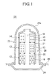
FIGS. 1 to 3 , thebattery module 101 according to the first exemplary embodiment of the present invention includes a plurality of rechargeable batteries (e.g., batteries) 10, ahousing 23 having space accommodating therechargeable batteries 10 therein, and aprotrusion 18 located between therechargeable batteries 10 and forming a space wherein a cooling medium moves. - The
rechargeable batteries 10 may be lithium ion rechargeable batteries and may have a prismatic shape such as a substantially rectangular parallelepiped shape. However, embodiments of the present invention is not limited thereto, but rather may be applied to various types of batteries such as a lithium polymer battery or a cylindrical battery. - The
rechargeable batteries 10 are stacked and arranged in parallel to formbattery arrays housing 23. Thebattery arrays center passage 19 therebetween and extending along the flow direction of the cooling medium. - The
battery arrays center passage 19 located therebetween, thus the cooling medium can move through thecenter passage 19 and thebattery arrays - In the exemplary embodiment, three
battery arrays - The
protrusion 18 is located between therechargeable batteries 10 to allow therechargeable batteries 10 to be spaced from each other. As a result, apassage 15 through which the cooling medium moves is formed between therechargeable batteries 10. - The
protrusion 18 according to the exemplary embodiment may be a dot protrusion which has a circular cross section, but the present invention is not limited thereto and the dot protrusion may be formed in various cross-sectional shapes such as a triangular shape, a quadrangular shape, and the like. Thedot protrusion 18 is fixed to acase 17 forming an external surface of therechargeable battery 10. Thedot protrusion 18 may be formed integrally with thecase 17 of therechargeable battery 10 to protrude from thecase 17 or may be fixed to thecase 17 by an adhesive, or the like. - The
housing 23 has a hexahedral shape and has a structure in which a cross sectional area increases in one direction (downward as shown inFIG. 1 ). Further, the top 23a of thehousing 23 is formed to have an arc-shaped cross section. As a result, the cooling medium which ascends is guided by the top 23a of thehousing 23 to easily move to an edge. - Meanwhile, a partitioning
member 21 is installed in thehousing 23 to provide a partitioning space through which the cooling medium moves. The partitioningmember 21 is made of a thermal insulating material and has a substantially hexahedral shape. Further, the partitioningmember 21 defines a coolingspace 27 adjacent to thebattery arrays battery arrays space 28 outside of the partitioningmember 21, thus allowing the cooling medium to be circulated and reintroduced into the coolingspace 27. - A first end and a second end of the partitioning
member 21 are open to allow the cooling medium to be introduced into the partitioningmember 21 and discharged therefrom. Further, the partitioningmember 21 is spaced from thehousing 23 and the movingspace 28 is formed between the partitioningmember 21 and thehousing 23. The movingspace 28 has a structure in which a cross section gradually increases along the flow direction of the cooling medium. As a result, when a cooling medium such as air discharged from the coolingspace 27 moves through the movingspace 28, the velocity of the air slows. Also, the cooling medium is in contact with thehousing 23 for an increased amount of time to thereby cool the cooling medium more quickly. - Further, a
bottom plate 24 which is in contact with external air is installed below thehousing 23. When thebattery module 101 is installed, for example, in an electric car or in a hybrid car, thebattery module 101 may be located in a rear trunk and thebottom plate 24 protrudes from the bottom of the vehicle to the outside to be installed in contact with the outdoor air. As a result, thebottom plate 24 is cooled by the outdoor air and the cooling medium discharged from the coolingspace 27 may be cooled through thehousing 23 and thebottom plate 24. Thehousing 23 and thebottom plate 24 may be made of aluminum, steel, stainless steel, or the like having high thermal conductivity. The internal space of thehousing 23 is sealed by thehousing 23 and thebottom plate 24, and air, which is the cooling medium, is introduced into the internal space. - A
frame 25 supporting thebattery arrays member 21. Theframe 25 has a bar shape and serves to support thebattery arrays member 21 to stably position thebattery arrays - The friction of the cooling medium with the
passage 15 of thebattery arrays passage 15 of thebattery array 12 located in the earlier part of the flow direction of the cooling medium (e.g., a second end of the cooling medium flow path). In other words, thebattery arrays battery array 12. - To achieve this, in one embodiment the number of
protrusions 18 arranged between therechargeable batteries 10 of thebattery arrays protrusions 18 located between therechargeable batteries 10 of thebattery array 12 located in the earlier part of the flow direction of the cooling medium. - The
protrusions 18 are spaced from each other. In one embodiment, eightprotrusions 18 are installed in therechargeable battery 10 of thebattery array 12 located in the earliest part (initial part) of the flow direction of the cooling medium, sixprotrusions 18 are installed in therechargeable battery 10 of thebattery array 13 located in the center, and four protrusions are in therechargeable battery 10 of thebattery array 14 located in the latter part of the flow direction of the cooling medium. Herein, theprotrusions 18 installed in therechargeable battery 10 of thebattery array 14 located in the earliest part are arranged to cross each other (i.e., they are not aligned with an adjacent protrusion with respect to the flow direction of the cooling medium) to thereby further increase the friction between the cooling medium and thedot protrusion 18. - In one embodiment, the cooling medium is formed by air and moves substantially in parallel to a direction in which the
battery arrays FIGs. 1 and4 . Therefore, thebattery arrays battery array 12 located in the earlier part of the flow direction of the cooling medium when the battery module is oriented upright in an operating orientation, as shown inFIG. 1 . - Air heated by the
rechargeable batteries 10 is moved upwards by buoyancy in the coolingspace 27 and as the air moves upwards, the air is heated to thereby increase the moving velocity. - The moving velocity of the cooling medium increases as the cooling medium moves upwards, such that the cooling medium moves to the outside of the partitioning
member 21. The cooling medium discharged from the coolingspace 27 formed in the partitioningmember 21 is cooled by exchanging heat with the housing and air cooled in the upper part moves downwards through the movingspace 28. Further, convection in which the air moves from the movingspace 28 to the coolingspace 27 having lower pressure occurs. Therechargeable batteries 10 are cooled through convection by the cooling medium. - In one embodiment, since comparatively
many protrusions 18 are formed in the lower part, the cooling medium slowly moves upwards. However, the number ofprotrusions 18 decreases towards the top so that the moving velocity of the cooling medium is increased. The temperature of the cooling medium increases due to therechargeable batteries 10 and causes the cooling medium to move upwards. The moving velocity of the cooling medium increases as it moves upwards due to the arrangement of theprotrusions 18. As a result, the cooling medium which moves upward pushes out the cooling medium which is located higher than the above-mentioned cooling medium to circulate the cooling medium through thehousing 23. - The moving velocity of the cooling medium helps convection. Therefore, as the moving velocity of the cooling medium increases, cooling by convection may increase. According to the exemplary embodiment, since the flow resistance of the passage of the cooling medium of the
battery arrays - Further, the cooling medium flowing upwards and the cooling medium flowing downwards are separated from each other by the partitioning
member 21. Therefore, since convection may more easily occur and the cooling medium is cooled by thehousing 23 and thebottom plate 24, the cooling medium flows upwards through the battery arrays and transfers heat to thehousing 23 while flowing downwards and circulates. - As such, according to the exemplary embodiment, since the
rechargeable batteries 10 are cooled by the convection and the cooling medium is recycled, it is possible to prevent external foreign materials from being introduced. -
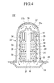
FIG. 4 is a cross-sectional view of a battery module according to a second exemplary embodiment of the present invention. - Referring to
FIG. 4 , thebattery module 102 according to the exemplary embodiment has substantially the same structure as the battery module according to the first exemplary embodiment except for the structure of theprotrusions member 37 and theguide members 38. Therefore, the same structure will not be described again. - The
battery module 102 according to the exemplary embodiment includes a plurality ofbattery arrays housing 23, andprotrusions rechargeable batteries 10 of thebattery arrays - The protrusions include a
dot protrusion 35 and aguide protrusion 36. Herein, thedot protrusions 35 have a circular or polygonal cross and are spaced from each other in the flow direction of the cooling medium on the surface of one rechargeable battery. The guide protrusions 36 are substantially rectangular protrusions extending in the flow direction of the cooling medium. - The number of
guide protrusions 36 located between therechargeable batteries 10 of thebattery array 34 located in the latter part of the flow direction of the cooling medium is smaller than the number ofdot protrusions 35 located between therechargeable batteries 10 of thebattery array - A plurality of
dot protrusions 35 are spaced from each other in the flow direction of the cooling medium in onerechargeable battery 10. Eightprotrusions 35 are installed in therechargeable battery 10 of thebattery array 32 located in the earliest part of the flow direction of the cooling medium and sixprotrusions 35 are installed in therechargeable battery 10 of thebattery array 33 disposed at the center. - In one embodiment, the length of the
guide protrusion 36 located between therechargeable batteries 10 of thebattery array 34 in the latter part of the flow direction of the cooling medium is greater than the length of thedot protrusions 35 located between the rechargeable batteries of thebattery array 34 located in the earlier part of the flow direction of the cooling medium. Further, the width of theguide protrusion 36 in the latter part of the flow direction of the cooling medium is smaller than the width of thedot protrusions 35 located in the earlier part of the flow direction of the cooling medium. - That is, the plurality of
guide protrusions 36 extending in the flow direction of the cooling medium are spaced from each other to allow a cooling medium to flow therebetween in the flow direction. - The
guide protrusion 36 has a bar shape extending in the flow direction of the cooling medium and extends from one end to the other end of therechargeable battery 10. - The
guide protrusion 36 reduces a cross section of the cooling medium passage or flow path without interrupting the flow of the cooling medium. As a result, the velocity of the cooling medium is further increased. In other words, theprotrusions 35 having a large width and a short length interrupts the progression of the cooling medium and distributes the cooling medium, but theguide protrusion 36 serves to reduce only the cross section of the cooling medium passage and allows the cooling medium to progress more rapidly. - As such, according to the exemplary embodiment, since the velocity of the cooling medium further increases toward the latter part with respect to the flow direction of the cooling medium, the convection in the housing may more actively occur.
- The
guide member 38 protrudes obliquely in the flow direction of the cooling medium and is installed on an outer surface of the partitioningmember 21. Theguide member 38 has a plate shape formed obliquely in the flow direction of the cooling medium and serves to prevent the cooling medium from flowing backward in the movingspace 28. - Further, the cooling
member 37 is installed on the top 23a of thehousing 23. The coolingmember 37 serves to cool thehousing 23 by receiving heat from thehousing 23. The coolingmember 37 may have various structures and may be made of a thermoelectric element, a metal plate transferring heat to other members, or the like. - A hole (e.g., opening) 37a is formed at the center the cooling
member 37 and aheat insulating member 39 is inserted into thehole 37a to be in contact with thehousing 23. As a result, the center portion of thehousing 23 is not cooled as much and only the edge portion of thehousing 23 is cooled. As a result, the heated cooling medium may move upwards at high speed towards the center portion of thehousing 23 and the cooling medium which moves upwards is cooled while moving to the edge of thehousing 23. The cooling medium which is cooled at the edge of thehousing 23 moves downwards in the movingspace 28 to cause the convection to more actively occur. As a result, cooling efficiency is improved. -
FIG. 5 is a cross-sectional view of a battery module according to a third exemplary embodiment of the present invention. - Referring to
FIG. 5 , thebattery module 103 according to the exemplary embodiment has substantially the same structure as the battery module according to the first exemplary embodiment except for the structure of aguide protrusion 45 and the addition of a coolingmember 47. Therefore, the same structure will not be described again. - The
battery module 103 according to the exemplary embodiment includes a plurality ofbattery arrays housing 23, and guideprotrusions 45 located betweenrechargeable batteries 10 of thebattery arrays - The plurality of
guide protrusions 45 that extend in a flow direction of a cooling medium are spaced from each other between therechargeable batteries 10 to allow a cooling medium to flow along a length of the protrusions. Eachguide protrusion 45 has a bar shape that extends in the flow direction of the cooling medium and extends from one end to the other end of therechargeable battery 10. - The number of
guide protrusions 45 of the rechargeable batteries of thebattery array 44 located in the most latter part of the flow direction of the cooling medium is larger than the number ofguide protrusions 45 located between therechargeable batteries 10 of thebattery array - The
guide protrusion 45 reduces a cross section of a cooling medium passage without significantly interrupting the flow of the cooling medium. Therefore, when the number ofguide protrusions 45 is increased, the width of the cooling medium passage is decreased. As a result, since the cross section of the passage is decreased, the moving velocity of the cooling medium is further increased and as the cross section of the cooling medium passage decreases, the friction between the cooling medium and the cooling medium passage is decreased. - As such, according to the exemplary embodiment, since the velocity of the cooling medium further increases toward the latter part with respect to the flow direction of the cooling medium, the convection in the
housing 23 may more actively occur. - Further, the cooling
member 47 is installed at the edge of the top 23a of thehousing 23. The coolingmember 47 serves to cool thehousing 23 by receiving heat from thehousing 23. The coolingmember 47 may be formed in various configurations and may be made of a thermoelectric element, a metal plate transferring heat to other members, or the like. As described in the exemplary embodiment, when the coolingmember 47 is installed at the edge of the top 23a of thehousing 23, the cooling medium which is heated by therechargeable battery 10 and thus moves upwards may easily move downwards on a moving passage while moving to the edge. Since the coolingmember 47 is omitted from the center portion of the top 23a, the cooling member is not provided on the top 23a of the housing, so that cooling space is open below the center portion of the top and causes the convection to occur more actively, thereby further improving cooling efficiency. -
FIG. 6 is a cross-sectional view of a battery module according to a fourth exemplary embodiment of the present invention. - Referring to
FIG. 6 , thebattery module 104 according to the exemplary embodiment has substantially the same structure as the battery module according to the third exemplary embodiment except for the configuration ofprotrusions member 58. Therefore, the same structure will not be described again. - The
battery module 104 according to the exemplary embodiment includes a plurality ofbattery arrays housing 23, andprotrusions rechargeable batteries 10 of thebattery arrays - Three
battery arrays first guide protrusion 55 is installed between therechargeable batteries 10 of thebattery array 52 located in the earliest part of the flow direction of the cooling medium and thebattery array 53 located at the center. Thefirst guide protrusion 55 has a bar shape extending in the flow direction of the cooling medium. Thefirst guide protrusion 55 is elongate and extends from one end to the other end of therechargeable battery 10. - The number of
first guide protrusions 55 located between the rechargeable batteries of thebattery array 53 located in the latter part of the flow direction of the cooling medium is larger than the number offirst guide protrusions 55 located between therechargeable batteries 10 of thebattery array 52 located in the earlier part of the flow direction of the cooling medium. - Further, a
second guide protrusion 57 and adot protrusion 56 are installed between therechargeable batteries 10 located in the latter part of thebattery arrays housing 23. Since the cooling medium in the centre passage moves from the bottom of thehousing 23 toward the top 23a, the batteries located closer to the top 23a of thehousing 23 are the last with respect to a flow direction of the cooling medium flow path.. Thesecond guide protrusion 57 is installed in the latter part of the protrusion on the basis of the flow direction of the cooling medium. As a result, the cooling medium passing through thedot protrusion 56 is guided by thesecond guide protrusion 57 to flow. - The
second guide protrusion 57 extends in the flow direction of the cooling medium. Therefore, thesecond guide protrusion 57 extends from one end to about the center portion of therechargeable battery 10. Thedot protrusion 56 is formed in a portion of the battery where thesecond guide protrusion 57 is absent. As described in the exemplary embodiment, when both thesecond guide protrusion 57 and thedot protrusion 56 are located on onerechargeable battery 10, the cooling medium and therechargeable battery 10 may be in contact with each other for enough time to cool therechargeable battery 10 by thedot protrusion 56 and the cooling medium which is in contact with the rechargeable battery may be rapidly discharged through thesecond guide protrusion 57. When both thedot protrusion 56 and thesecond guide protrusion 57 are located on the same battery, cooling may be stably performed. - In one embodiment, the cooling
member 58 is attached to an outer surface of thehousing 23. Therefore, the coolingmember 58 is in contact with thehousing 23 while extending from the top 23a of thehousing 23 to theside 23b of thehousing 23. According to the exemplary embodiment, since the coolingmember 58 is in contact with thehousing 23 through a sufficient area, the cooling medium which moves to the upper part of thehousing 23 may be cooled through the top 23a and is cooled by contacting theside 23b while passing through moving space. As a result, convection may occur more actively. - As such, according to the exemplary embodiment, since the velocity of the cooling medium further increases toward the latter part (i.e., towards the second end) of the cooling medium flow path, the convection in the
housing 23 may occur more actively. - Further, the cooling
member 58 is installed at the edge of the top 23a of thehousing 23. The coolingmember 58 serves to cool thehousing 23 by receiving heat from thehousing 23. The coolingmember 58 may have various structures and may be made of a thermoelectric element, a metal plate transferring heat to other members, or the like. -
FIG. 7 is an exploded perspective view of rechargeable batteries constituting a battery module according to a fifth exemplary embodiment of the present invention. - Referring to
FIG. 7 , the battery module according to the exemplary embodiment has substantially the same structure as the battery module according to the first exemplary embodiment except for the configuration ofpartitions - The battery module according to the exemplary embodiment includes a plurality of
battery arrays battery arrays protrusions rechargeable batteries 10. - The
protrusions plate materials rechargeable batteries 10. Therefore, theprotrusions plate materials partitions partitions rechargeable batteries 10 to form a passage of a cooling medium. - The number of
protrusions 67b of thepartition 67 located in the latter part of the flow direction of the cooling medium is smaller than the number ofprotrusions partitions - According to the exemplary embodiment, since the
protrusion partitions partitions rechargeable batteries 10, such that theprotrusions rechargeable batteries 10. -
FIG. 8 is a cross-sectional view of a battery module according to a sixth exemplary embodiment of the present invention. - Referring to
FIG. 8 , thebattery module 105 according to the exemplary embodiment has substantially the same structure as the battery module according to the first exemplary embodiment except for the configuration of ahousing 72 and ablower 75. Therefore, the same structure will not be described again. - The
battery module 105 according to the exemplary embodiment includes a plurality ofbattery arrays housing 72, andprotrusions 18 located betweenrechargeable batteries 10 of thebattery arrays - The
housing 72 has a generally hexahedral body. Aninlet 72a through which a cooling medium is introduced is formed at one end of thehousing 72 and anoutlet 72b through which the cooling medium is discharged is formed at the other end of thehousing 72. Theblower 75 compulsorily introducing the cooling medium into thehousing 72 is installed in theinlet 72a. The cooling medium is formed by air and theblower 75 may be formed by a fan compulsorily transferring air. - Meanwhile, like the first exemplary embodiment, the number of
protrusions 18 located between therechargeable batteries 10 of thebattery array 14 located in the latter part of the flow direction of the cooling medium is smaller than the number ofprotrusions 18 located between therechargeable batteries 10 of thebattery array - As a result, the friction between the
battery arrays battery array 14 located in the latter part of the flow direction of the cooling medium and the cooling medium. - According to the exemplary embodiment, since the velocity of the cooling medium increases to the latter part of the flow direction the cooling medium is supplied by the
blower 75, the cooling medium may be rapidly moved even with small power. As a result, the cooling efficiency of thebattery module 105 is improved and the loss of electric power by theblower 75 can be minimized. - While this invention has been described in connection with what is presently considered to be practical exemplary embodiments, it is to be understood that the invention is not limited to the disclosed embodiments, but, on the contrary, is intended to cover various modifications and equivalent arrangements included within the scope of the appended claims.
-
10: Rechargeable battery 101, 102, 103, 104, 105: Battery module 12, 13, 14, 32, 33, 34, 42, 43, 44, 52, 53, 54, 62, 63, 64: Battery array 17: Case 18, 35, 56, 65b, 66b, 67b: Protrusion 19: Center passage 21: Partitioning member 23, 72: Housing 23a: Top 23b: Side 24: Bottom plate 25: Frame 27: Cooling space 28: Moving space 36: Guide protrusion 37, 47, 58: Cooling member 38: Guide member 55: First guide protrusion 57: Second guide protrusion 65, 66, 67: Partition 65a, 66a, 67a: Plate material 72a: Inlet 72b: Outlet 75: Blower
Claims (15)
- A battery module (101, 102, 103, 104, 105) comprising:a plurality of batteries (10) stacked together to form a plurality of battery arrays (12, 13, 14, 32, 33, 34, 42, 43, 44, 52, 53, 54, 62, 63, 64), wherein a first group of the battery arrays (12, 13, 14, 32, 33, 34, 42, 43, 44, 52, 53, 54, 62, 63, 64) are aligned together and a second group of the battery arrays (12, 13, 14, 32, 33, 34, 42, 43, 44, 52, 53, 54, 62, 63, 64) are aligned together, and wherein the first group and the second group are spaced from each other to create a cooling medium flow path (19) therebetween, the cooling medium flow path (19) having a first end and a second end, wherein a cooling medium has a flow direction going from the first end toward the second end;a housing (23) accommodating the batteries (10); anda plurality of protrusions (18, 35, 36, 45, 55, 56, 57, 65b, 66b, 67b) on each of the batteries (10) for spacing the batteries (10) from each other, wherein a number of protrusions (18, 35, 36, 45, 55, 56, 57, 65b, 66b, 67b) on a first battery of the batteries (10) is different from a number of protrusions (18, 35, 36, 45, 55, 56, 57, 65b, 66b, 67b) on a second battery adjacent to the first battery with respect to a flow direction of the cooling medium flow path (19).
- The battery module of claim 1, wherein the first battery is located closer to the first end of the cooling medium flow path (19) than the second battery, and
wherein the protrusions (18, 35, 65b, 66b, 67b) have a dot shape and the number of protrusions (18, 35, 65b) on the first battery is greater than the number of protrusions (18, 35, 66b) on the second battery, or
wherein the protrusions (45, 55) have an elongate shape and the number of protrusions (45, 55) on the first battery is smaller than the number of protrusions (45, 55) on the second battery. - The battery module of one of the preceding claims, wherein the protrusions (18, 35, 36, 45, 55, 56, 57, 65b, 66b, 67b) are spaced from each other on an outer surface of each of the batteries (10).
- The battery module of claim 2, wherein a width of a first protrusion (35) of the protrusions located on the first battery is greater than a width of a second protrusion (36) of the protrusions located on the second battery, and/or
wherein a length of a first protrusion of the protrusions (35) located on the first battery is less than a length of a second protrusion (36) of the protrusions located on the second battery. - The battery module of one of the preceding claims, wherein the protrusions (18, 35, 36, 45, 55, 56, 57, 65b, 66b, 67b) comprise guide protrusions (36, 45, 55, 57) that are elongate and extend in a direction from the first end to the second end of the cooling medium flow path (19).
- The battery module of one of the preceding claims, wherein the housing (23) is sealed and is configured to allow the batteries (10) to be cooled by convection.
- The battery module of claim 6, wherein the first group of battery arrays (12, 13, 14, 32, 33, 34, 42, 43, 44, 52, 53, 54) extends along a first side of the cooling medium flow path (19) and the second group of battery arrays (12, 13, 14, 32, 33, 34, 42, 43, 44, 52, 53, 54) extends along a second side of the cooling medium flow path (19) parallel to the first group.
- The battery module of claim 6, further comprising a partitioning member (21), wherein the first group and the second group of battery arrays (12, 13, 14, 32, 33, 34, 42, 43, 44, 52, 53, 54) are located within the partitioning member (21), wherein a cooling space (27) is defined within the partitioning member (21) and a moving space (28) is defined outside of the partitioning member (21), and wherein the partitioning member is configured so that a cooling medium can move between the cooling space (27) and the moving space (28).
- The battery module of claim 8, wherein the partitioning member (21) comprises a thermal insulating material.
- The battery module of one of claims 8 and 9, further comprising a guide member (38) formed on the partitioning member (21), wherein the guide member (38) extends obliquely from the partitioning member (21) into the moving space (28).
- The battery module of one of the preceding claims, wherein the housing (23) further comprises:a bottom plate (24) configured to be exposed to exterior air, and/ora cooling member (37, 47, 58) connected to the housing (23).
- The battery module of claim 11, wherein the cooling member (37, 47, 58) is located at one end of the housing (23) or at an edge of the housing (23).
- The battery module of claim 12, wherein the cooling member (37) has an opening (37a) and wherein a heat insulating member (39) is in the opening (37a) and contacts the housing (23).
- The battery module of one of the preceding claims,
wherein the protrusions (18, 35, 36, 45, 55, 56, 57) are fixed to a case of the battery (10) or
wherein the protrusions (65b, 66b, 67b) are fixed to a plate (65a, 66a, 67a) located between the batteries (10). - The battery module of claim 1, wherein the protrusions (35, 36, 55, 56, 57) comprise guide protrusions (36, 55, 57) that are elongate and extend in a flow direction of the cooling medium flow path (19) and dot protrusions (35, 56) having a greater width and a shorter length than the guide protrusions (36, 55, 57), and wherein the dot protrusions (35, 56) are closer to a first end of the flow path channel than the guide protrusions (36, 55, 57).
Applications Claiming Priority (1)
| Application Number | Priority Date | Filing Date | Title |
|---|---|---|---|
| KR1020100060117A KR101191664B1 (en) | 2010-06-24 | 2010-06-24 | Battery module |
Publications (2)
| Publication Number | Publication Date |
|---|---|
| EP2400580A1 true EP2400580A1 (en) | 2011-12-28 |
| EP2400580B1 EP2400580B1 (en) | 2013-02-20 |
Family
ID=43754972
Family Applications (1)
| Application Number | Title | Priority Date | Filing Date |
|---|---|---|---|
| EP20100196689 Active EP2400580B1 (en) | 2010-06-24 | 2010-12-23 | Battery module and cooling thereof |
Country Status (3)
| Country | Link |
|---|---|
| US (1) | US20110318625A1 (en) |
| EP (1) | EP2400580B1 (en) |
| KR (1) | KR101191664B1 (en) |
Cited By (1)
| Publication number | Priority date | Publication date | Assignee | Title |
|---|---|---|---|---|
| EP3240063A1 (en) * | 2016-04-25 | 2017-11-01 | LG Chem, Ltd. | Energy storage apparatus and method for cooling the energy storage apparatus |
Families Citing this family (11)
| Publication number | Priority date | Publication date | Assignee | Title |
|---|---|---|---|---|
| DE102008051085A1 (en) * | 2008-10-09 | 2010-04-15 | Dr.Ing.H.C.F.Porsche Aktiengesellschaft | battery assembly |
| US8852789B2 (en) | 2010-11-04 | 2014-10-07 | Samsung Sdi Co., Ltd. | Battery module having battery cell holder |
| US8980457B2 (en) | 2010-11-04 | 2015-03-17 | Samsung Sdi Co., Ltd. | Battery module |
| KR101535800B1 (en) * | 2012-03-08 | 2015-07-10 | 주식회사 엘지화학 | Battery Pack of Novel Air Cooling Structure |
| JP5927702B2 (en) * | 2012-09-12 | 2016-06-01 | 株式会社日立製作所 | Battery pack and container equipped with the same |
| JP2014135173A (en) * | 2013-01-09 | 2014-07-24 | Toyota Industries Corp | Battery pack |
| US10381614B2 (en) * | 2013-04-17 | 2019-08-13 | Samsung Sdi Co., Ltd. | Battery module |
| DE102015109954A1 (en) * | 2015-06-22 | 2016-12-22 | Vorwerk & Co. Interholding Gmbh | vacuum cleaning |
| US11135910B2 (en) * | 2017-06-25 | 2021-10-05 | Brp-Rotax Gmbh & Co. Kg | Electric kart and battery |
| DE102018222704A1 (en) * | 2018-12-21 | 2020-06-25 | Mahle International Gmbh | accumulator |
| KR20210147657A (en) * | 2020-05-29 | 2021-12-07 | 주식회사 엘지에너지솔루션 | Heat sink |
Citations (5)
| Publication number | Priority date | Publication date | Assignee | Title |
|---|---|---|---|---|
| JP2003317812A (en) * | 2002-04-19 | 2003-11-07 | Toyota Motor Corp | Assembled battery and battery system |
| US20050058892A1 (en) * | 1993-10-25 | 2005-03-17 | Ovshinsky Stanford R. | Mechanical and thermal improvements in metal hydride batteries, battery modules, and battery packs |
| US20060028183A1 (en) * | 2004-07-23 | 2006-02-09 | Ryosaku Izawa | Battery device of vehicle power supply |
| US20060049799A1 (en) * | 2004-09-06 | 2006-03-09 | Toyota Jidosha Kabushiki Kaisha | Battery pack |
| EP1746679A1 (en) * | 2003-06-03 | 2007-01-24 | TechTronic Industries, Co., Ltd | Battery charger |
Family Cites Families (7)
| Publication number | Priority date | Publication date | Assignee | Title |
|---|---|---|---|---|
| JPS5796852A (en) * | 1980-12-09 | 1982-06-16 | Matsushita Electric Ind Co Ltd | Heat insulating material |
| WO2002031906A1 (en) * | 2000-10-12 | 2002-04-18 | Rayovac Corporation | Improved air manager for metal-air cells |
| US7138205B2 (en) * | 2001-10-02 | 2006-11-21 | Matsushita Electric Industrial Co., Ltd. | Battery with proportional collectors, straps, and plates |
| JP4308515B2 (en) * | 2002-12-27 | 2009-08-05 | パナソニック株式会社 | Battery module |
| US20060093901A1 (en) * | 2004-10-28 | 2006-05-04 | Gun-Goo Lee | Secondary battery module and cooling apparatus for secondary battery module |
| KR100709261B1 (en) * | 2005-11-15 | 2007-04-19 | 삼성에스디아이 주식회사 | Secondary battery module |
| KR100951324B1 (en) | 2007-06-14 | 2010-04-08 | 주식회사 엘지화학 | Middle or Large-sized Battery Pack Case Providing Improved Distribution Uniformity of Coolant Flux |
-
2010
- 2010-06-24 KR KR1020100060117A patent/KR101191664B1/en active IP Right Grant
- 2010-10-11 US US12/902,044 patent/US20110318625A1/en not_active Abandoned
- 2010-12-23 EP EP20100196689 patent/EP2400580B1/en active Active
Patent Citations (5)
| Publication number | Priority date | Publication date | Assignee | Title |
|---|---|---|---|---|
| US20050058892A1 (en) * | 1993-10-25 | 2005-03-17 | Ovshinsky Stanford R. | Mechanical and thermal improvements in metal hydride batteries, battery modules, and battery packs |
| JP2003317812A (en) * | 2002-04-19 | 2003-11-07 | Toyota Motor Corp | Assembled battery and battery system |
| EP1746679A1 (en) * | 2003-06-03 | 2007-01-24 | TechTronic Industries, Co., Ltd | Battery charger |
| US20060028183A1 (en) * | 2004-07-23 | 2006-02-09 | Ryosaku Izawa | Battery device of vehicle power supply |
| US20060049799A1 (en) * | 2004-09-06 | 2006-03-09 | Toyota Jidosha Kabushiki Kaisha | Battery pack |
Cited By (2)
| Publication number | Priority date | Publication date | Assignee | Title |
|---|---|---|---|---|
| EP3240063A1 (en) * | 2016-04-25 | 2017-11-01 | LG Chem, Ltd. | Energy storage apparatus and method for cooling the energy storage apparatus |
| US10164305B2 (en) | 2016-04-25 | 2018-12-25 | Lg Chem, Ltd. | Energy storage apparatus and method for cooling the energy storage apparatus |
Also Published As
| Publication number | Publication date |
|---|---|
| US20110318625A1 (en) | 2011-12-29 |
| EP2400580B1 (en) | 2013-02-20 |
| KR101191664B1 (en) | 2012-10-17 |
| KR20110139973A (en) | 2011-12-30 |
Similar Documents
| Publication | Publication Date | Title |
|---|---|---|
| EP2400580A1 (en) | Battery module and cooling thereof | |
| US11495848B2 (en) | Secondary battery module | |
| JP4659699B2 (en) | Battery module | |
| CN102884671B (en) | There is the battery housing of new structure | |
| US9614260B2 (en) | Battery pack of excellent cooling efficiency | |
| JP5052057B2 (en) | Power supply | |
| US7746034B2 (en) | Battery module | |
| KR102142669B1 (en) | Air cooling type Battery Module having Guide vane | |
| EP2642586B1 (en) | Battery pack having improved cooling efficiency | |
| KR101560561B1 (en) | Battery Module with Compact Structure and Excellent Heat Radiation Characteristics and Middle or Large-sized Battery Pack Employed with the Same | |
| US8586228B2 (en) | Battery module | |
| US8748027B2 (en) | Middle or large-sized battery pack case providing improved distribution uniformity of coolant flux | |
| US20060214633A1 (en) | Rechargeable battery module | |
| KR100696669B1 (en) | Secondary battery module | |
| US20080268328A1 (en) | Battery module | |
| JP4592469B2 (en) | Assembled battery | |
| US10177422B2 (en) | Battery module | |
| US11509008B2 (en) | Heat exchanger with thermoelectric module and system for managing heat of battery including same | |
| US20130017428A1 (en) | Rack housing assembly and energy storage apparatus having the same | |
| US20090311586A1 (en) | Middle- or large-sized battery pack case providing improved distribution uniformity in coolant flux | |
| JP2007048750A (en) | Battery module | |
| EP3067962B1 (en) | Battery pack | |
| KR102284489B1 (en) | Battery pack | |
| KR102071134B1 (en) | Battery cooling device for vehicle | |
| CN116097499A (en) | Battery module, battery pack including the same, and vehicle |
Legal Events
| Date | Code | Title | Description |
|---|---|---|---|
| 17P | Request for examination filed |
Effective date: 20101223 |
|
| AK | Designated contracting states |
Kind code of ref document: A1 Designated state(s): AL AT BE BG CH CY CZ DE DK EE ES FI FR GB GR HR HU IE IS IT LI LT LU LV MC MK MT NL NO PL PT RO RS SE SI SK SM TR |
|
| AX | Request for extension of the european patent |
Extension state: BA ME |
|
| PUAI | Public reference made under article 153(3) epc to a published international application that has entered the european phase |
Free format text: ORIGINAL CODE: 0009012 |
|
| 17Q | First examination report despatched |
Effective date: 20111221 |
|
| GRAP | Despatch of communication of intention to grant a patent |
Free format text: ORIGINAL CODE: EPIDOSNIGR1 |
|
| GRAS | Grant fee paid |
Free format text: ORIGINAL CODE: EPIDOSNIGR3 |
|
| GRAA | (expected) grant |
Free format text: ORIGINAL CODE: 0009210 |
|
| AK | Designated contracting states |
Kind code of ref document: B1 Designated state(s): AL AT BE BG CH CY CZ DE DK EE ES FI FR GB GR HR HU IE IS IT LI LT LU LV MC MK MT NL NO PL PT RO RS SE SI SK SM TR |
|
| REG | Reference to a national code |
Ref country code: GB Ref legal event code: FG4D |
|
| RAP2 | Party data changed (patent owner data changed or rights of a patent transferred) |
Owner name: SAMSUNG SDI CO., LTD. Owner name: ROBERT BOSCH GMBH |
|
| REG | Reference to a national code |
Ref country code: CH Ref legal event code: EP |
|
| REG | Reference to a national code |
Ref country code: AT Ref legal event code: REF Ref document number: 597866 Country of ref document: AT Kind code of ref document: T Effective date: 20130315 |
|
| REG | Reference to a national code |
Ref country code: IE Ref legal event code: FG4D |
|
| REG | Reference to a national code |
Ref country code: DE Ref legal event code: R096 Ref document number: 602010005104 Country of ref document: DE Effective date: 20130418 |
|
| REG | Reference to a national code |
Ref country code: DE Ref legal event code: R081 Ref document number: 602010005104 Country of ref document: DE Owner name: SAMSUNG SDI CO., LTD., KR Free format text: FORMER OWNER: SB LIMOTIVE CO., LTD., SUWON-SI, KR Effective date: 20130318 Ref country code: DE Ref legal event code: R081 Ref document number: 602010005104 Country of ref document: DE Owner name: ROBERT BOSCH GMBH, DE Free format text: FORMER OWNER: SB LIMOTIVE CO., LTD., SUWON-SI, KR Effective date: 20130318 Ref country code: DE Ref legal event code: R081 Ref document number: 602010005104 Country of ref document: DE Owner name: ROBERT BOSCH GMBH, DE Free format text: FORMER OWNER: SB LIMOTIVE CO., LTD., SUWON-SI, KYONGGI-DO, KR Effective date: 20130318 Ref country code: DE Ref legal event code: R081 Ref document number: 602010005104 Country of ref document: DE Owner name: SAMSUNG SDI CO., LTD., YONGIN-SI, KR Free format text: FORMER OWNER: SB LIMOTIVE CO., LTD., SUWON-SI, KYONGGI-DO, KR Effective date: 20130318 |
|
| REG | Reference to a national code |
Ref country code: FR Ref legal event code: TQ Owner name: ROBERT BOSCH GMBH, DE Effective date: 20130424 Ref country code: FR Ref legal event code: TQ Owner name: SAMSUNG SDI CO., LTD., KR Effective date: 20130424 |
|
| REG | Reference to a national code |
Ref country code: AT Ref legal event code: MK05 Ref document number: 597866 Country of ref document: AT Kind code of ref document: T Effective date: 20130220 |
|
| REG | Reference to a national code |
Ref country code: NL Ref legal event code: VDEP Effective date: 20130220 |
|
| REG | Reference to a national code |
Ref country code: LT Ref legal event code: MG4D |
|
| PG25 | Lapsed in a contracting state [announced via postgrant information from national office to epo] |
Ref country code: NO Free format text: LAPSE BECAUSE OF FAILURE TO SUBMIT A TRANSLATION OF THE DESCRIPTION OR TO PAY THE FEE WITHIN THE PRESCRIBED TIME-LIMIT Effective date: 20130520 Ref country code: LT Free format text: LAPSE BECAUSE OF FAILURE TO SUBMIT A TRANSLATION OF THE DESCRIPTION OR TO PAY THE FEE WITHIN THE PRESCRIBED TIME-LIMIT Effective date: 20130220 Ref country code: AT Free format text: LAPSE BECAUSE OF FAILURE TO SUBMIT A TRANSLATION OF THE DESCRIPTION OR TO PAY THE FEE WITHIN THE PRESCRIBED TIME-LIMIT Effective date: 20130220 Ref country code: SE Free format text: LAPSE BECAUSE OF FAILURE TO SUBMIT A TRANSLATION OF THE DESCRIPTION OR TO PAY THE FEE WITHIN THE PRESCRIBED TIME-LIMIT Effective date: 20130220 Ref country code: ES Free format text: LAPSE BECAUSE OF FAILURE TO SUBMIT A TRANSLATION OF THE DESCRIPTION OR TO PAY THE FEE WITHIN THE PRESCRIBED TIME-LIMIT Effective date: 20130531 Ref country code: BG Free format text: LAPSE BECAUSE OF FAILURE TO SUBMIT A TRANSLATION OF THE DESCRIPTION OR TO PAY THE FEE WITHIN THE PRESCRIBED TIME-LIMIT Effective date: 20130520 Ref country code: IS Free format text: LAPSE BECAUSE OF FAILURE TO SUBMIT A TRANSLATION OF THE DESCRIPTION OR TO PAY THE FEE WITHIN THE PRESCRIBED TIME-LIMIT Effective date: 20130620 |
|
| PG25 | Lapsed in a contracting state [announced via postgrant information from national office to epo] |
Ref country code: GR Free format text: LAPSE BECAUSE OF FAILURE TO SUBMIT A TRANSLATION OF THE DESCRIPTION OR TO PAY THE FEE WITHIN THE PRESCRIBED TIME-LIMIT Effective date: 20130521 Ref country code: BE Free format text: LAPSE BECAUSE OF FAILURE TO SUBMIT A TRANSLATION OF THE DESCRIPTION OR TO PAY THE FEE WITHIN THE PRESCRIBED TIME-LIMIT Effective date: 20130220 Ref country code: SI Free format text: LAPSE BECAUSE OF FAILURE TO SUBMIT A TRANSLATION OF THE DESCRIPTION OR TO PAY THE FEE WITHIN THE PRESCRIBED TIME-LIMIT Effective date: 20130220 Ref country code: FI Free format text: LAPSE BECAUSE OF FAILURE TO SUBMIT A TRANSLATION OF THE DESCRIPTION OR TO PAY THE FEE WITHIN THE PRESCRIBED TIME-LIMIT Effective date: 20130220 Ref country code: PL Free format text: LAPSE BECAUSE OF FAILURE TO SUBMIT A TRANSLATION OF THE DESCRIPTION OR TO PAY THE FEE WITHIN THE PRESCRIBED TIME-LIMIT Effective date: 20130220 Ref country code: PT Free format text: LAPSE BECAUSE OF FAILURE TO SUBMIT A TRANSLATION OF THE DESCRIPTION OR TO PAY THE FEE WITHIN THE PRESCRIBED TIME-LIMIT Effective date: 20130620 Ref country code: LV Free format text: LAPSE BECAUSE OF FAILURE TO SUBMIT A TRANSLATION OF THE DESCRIPTION OR TO PAY THE FEE WITHIN THE PRESCRIBED TIME-LIMIT Effective date: 20130220 |
|
| PG25 | Lapsed in a contracting state [announced via postgrant information from national office to epo] |
Ref country code: HR Free format text: LAPSE BECAUSE OF FAILURE TO SUBMIT A TRANSLATION OF THE DESCRIPTION OR TO PAY THE FEE WITHIN THE PRESCRIBED TIME-LIMIT Effective date: 20130220 Ref country code: RS Free format text: LAPSE BECAUSE OF FAILURE TO SUBMIT A TRANSLATION OF THE DESCRIPTION OR TO PAY THE FEE WITHIN THE PRESCRIBED TIME-LIMIT Effective date: 20130220 |
|
| PG25 | Lapsed in a contracting state [announced via postgrant information from national office to epo] |
Ref country code: CZ Free format text: LAPSE BECAUSE OF FAILURE TO SUBMIT A TRANSLATION OF THE DESCRIPTION OR TO PAY THE FEE WITHIN THE PRESCRIBED TIME-LIMIT Effective date: 20130220 Ref country code: DK Free format text: LAPSE BECAUSE OF FAILURE TO SUBMIT A TRANSLATION OF THE DESCRIPTION OR TO PAY THE FEE WITHIN THE PRESCRIBED TIME-LIMIT Effective date: 20130220 Ref country code: NL Free format text: LAPSE BECAUSE OF FAILURE TO SUBMIT A TRANSLATION OF THE DESCRIPTION OR TO PAY THE FEE WITHIN THE PRESCRIBED TIME-LIMIT Effective date: 20130220 Ref country code: EE Free format text: LAPSE BECAUSE OF FAILURE TO SUBMIT A TRANSLATION OF THE DESCRIPTION OR TO PAY THE FEE WITHIN THE PRESCRIBED TIME-LIMIT Effective date: 20130220 Ref country code: RO Free format text: LAPSE BECAUSE OF FAILURE TO SUBMIT A TRANSLATION OF THE DESCRIPTION OR TO PAY THE FEE WITHIN THE PRESCRIBED TIME-LIMIT Effective date: 20130220 Ref country code: SK Free format text: LAPSE BECAUSE OF FAILURE TO SUBMIT A TRANSLATION OF THE DESCRIPTION OR TO PAY THE FEE WITHIN THE PRESCRIBED TIME-LIMIT Effective date: 20130220 |
|
| PLBE | No opposition filed within time limit |
Free format text: ORIGINAL CODE: 0009261 |
|
| STAA | Information on the status of an ep patent application or granted ep patent |
Free format text: STATUS: NO OPPOSITION FILED WITHIN TIME LIMIT |
|
| PG25 | Lapsed in a contracting state [announced via postgrant information from national office to epo] |
Ref country code: IT Free format text: LAPSE BECAUSE OF FAILURE TO SUBMIT A TRANSLATION OF THE DESCRIPTION OR TO PAY THE FEE WITHIN THE PRESCRIBED TIME-LIMIT Effective date: 20130220 |
|
| 26N | No opposition filed |
Effective date: 20131121 |
|
| REG | Reference to a national code |
Ref country code: DE Ref legal event code: R097 Ref document number: 602010005104 Country of ref document: DE Effective date: 20131121 |
|
| PG25 | Lapsed in a contracting state [announced via postgrant information from national office to epo] |
Ref country code: LU Free format text: LAPSE BECAUSE OF FAILURE TO SUBMIT A TRANSLATION OF THE DESCRIPTION OR TO PAY THE FEE WITHIN THE PRESCRIBED TIME-LIMIT Effective date: 20131223 |
|
| REG | Reference to a national code |
Ref country code: IE Ref legal event code: MM4A |
|
| PG25 | Lapsed in a contracting state [announced via postgrant information from national office to epo] |
Ref country code: IE Free format text: LAPSE BECAUSE OF NON-PAYMENT OF DUE FEES Effective date: 20131223 |
|
| PG25 | Lapsed in a contracting state [announced via postgrant information from national office to epo] |
Ref country code: MC Free format text: LAPSE BECAUSE OF FAILURE TO SUBMIT A TRANSLATION OF THE DESCRIPTION OR TO PAY THE FEE WITHIN THE PRESCRIBED TIME-LIMIT Effective date: 20130220 |
|
| PG25 | Lapsed in a contracting state [announced via postgrant information from national office to epo] |
Ref country code: SM Free format text: LAPSE BECAUSE OF FAILURE TO SUBMIT A TRANSLATION OF THE DESCRIPTION OR TO PAY THE FEE WITHIN THE PRESCRIBED TIME-LIMIT Effective date: 20130220 |
|
| PG25 | Lapsed in a contracting state [announced via postgrant information from national office to epo] |
Ref country code: TR Free format text: LAPSE BECAUSE OF FAILURE TO SUBMIT A TRANSLATION OF THE DESCRIPTION OR TO PAY THE FEE WITHIN THE PRESCRIBED TIME-LIMIT Effective date: 20130220 Ref country code: CY Free format text: LAPSE BECAUSE OF FAILURE TO SUBMIT A TRANSLATION OF THE DESCRIPTION OR TO PAY THE FEE WITHIN THE PRESCRIBED TIME-LIMIT Effective date: 20130220 |
|
| PG25 | Lapsed in a contracting state [announced via postgrant information from national office to epo] |
Ref country code: MK Free format text: LAPSE BECAUSE OF FAILURE TO SUBMIT A TRANSLATION OF THE DESCRIPTION OR TO PAY THE FEE WITHIN THE PRESCRIBED TIME-LIMIT Effective date: 20130220 Ref country code: HU Free format text: LAPSE BECAUSE OF FAILURE TO SUBMIT A TRANSLATION OF THE DESCRIPTION OR TO PAY THE FEE WITHIN THE PRESCRIBED TIME-LIMIT; INVALID AB INITIO Effective date: 20101223 |
|
| REG | Reference to a national code |
Ref country code: CH Ref legal event code: PL |
|
| PG25 | Lapsed in a contracting state [announced via postgrant information from national office to epo] |
Ref country code: MT Free format text: LAPSE BECAUSE OF FAILURE TO SUBMIT A TRANSLATION OF THE DESCRIPTION OR TO PAY THE FEE WITHIN THE PRESCRIBED TIME-LIMIT Effective date: 20130220 |
|
| PG25 | Lapsed in a contracting state [announced via postgrant information from national office to epo] |
Ref country code: LI Free format text: LAPSE BECAUSE OF NON-PAYMENT OF DUE FEES Effective date: 20141231 Ref country code: CH Free format text: LAPSE BECAUSE OF NON-PAYMENT OF DUE FEES Effective date: 20141231 |
|
| REG | Reference to a national code |
Ref country code: FR Ref legal event code: PLFP Year of fee payment: 6 |
|
| REG | Reference to a national code |
Ref country code: FR Ref legal event code: PLFP Year of fee payment: 7 |
|
| REG | Reference to a national code |
Ref country code: FR Ref legal event code: PLFP Year of fee payment: 8 |
|
| PG25 | Lapsed in a contracting state [announced via postgrant information from national office to epo] |
Ref country code: AL Free format text: LAPSE BECAUSE OF FAILURE TO SUBMIT A TRANSLATION OF THE DESCRIPTION OR TO PAY THE FEE WITHIN THE PRESCRIBED TIME-LIMIT Effective date: 20130220 |
|
| REG | Reference to a national code |
Ref country code: DE Ref legal event code: R079 Ref document number: 602010005104 Country of ref document: DE Free format text: PREVIOUS MAIN CLASS: H01M0002140000 Ipc: H01M0050400000 |
|
| P01 | Opt-out of the competence of the unified patent court (upc) registered |
Effective date: 20230528 |
|
| PGFP | Annual fee paid to national office [announced via postgrant information from national office to epo] |
Ref country code: GB Payment date: 20231130 Year of fee payment: 14 |
|
| PGFP | Annual fee paid to national office [announced via postgrant information from national office to epo] |
Ref country code: FR Payment date: 20231212 Year of fee payment: 14 Ref country code: DE Payment date: 20231128 Year of fee payment: 14 |