EP4495517A1 - Refrigeration appliance with a door projection to reduce thermal transfer at door and cabinet interface - Google Patents
Refrigeration appliance with a door projection to reduce thermal transfer at door and cabinet interface Download PDFInfo
- Publication number
- EP4495517A1 EP4495517A1 EP24189466.6A EP24189466A EP4495517A1 EP 4495517 A1 EP4495517 A1 EP 4495517A1 EP 24189466 A EP24189466 A EP 24189466A EP 4495517 A1 EP4495517 A1 EP 4495517A1
- Authority
- EP
- European Patent Office
- Prior art keywords
- door
- cabinet
- trim breaker
- horizontal wall
- wall
- Prior art date
- Legal status (The legal status is an assumption and is not a legal conclusion. Google has not performed a legal analysis and makes no representation as to the accuracy of the status listed.)
- Withdrawn
Links
Images







Classifications
-
- F—MECHANICAL ENGINEERING; LIGHTING; HEATING; WEAPONS; BLASTING
- F25—REFRIGERATION OR COOLING; COMBINED HEATING AND REFRIGERATION SYSTEMS; HEAT PUMP SYSTEMS; MANUFACTURE OR STORAGE OF ICE; LIQUEFACTION SOLIDIFICATION OF GASES
- F25D—REFRIGERATORS; COLD ROOMS; ICE-BOXES; COOLING OR FREEZING APPARATUS NOT OTHERWISE PROVIDED FOR
- F25D11/00—Self-contained movable devices, e.g. domestic refrigerators
-
- F—MECHANICAL ENGINEERING; LIGHTING; HEATING; WEAPONS; BLASTING
- F25—REFRIGERATION OR COOLING; COMBINED HEATING AND REFRIGERATION SYSTEMS; HEAT PUMP SYSTEMS; MANUFACTURE OR STORAGE OF ICE; LIQUEFACTION SOLIDIFICATION OF GASES
- F25D—REFRIGERATORS; COLD ROOMS; ICE-BOXES; COOLING OR FREEZING APPARATUS NOT OTHERWISE PROVIDED FOR
- F25D23/00—General constructional features
- F25D23/06—Walls
- F25D23/062—Walls defining a cabinet
-
- F—MECHANICAL ENGINEERING; LIGHTING; HEATING; WEAPONS; BLASTING
- F25—REFRIGERATION OR COOLING; COMBINED HEATING AND REFRIGERATION SYSTEMS; HEAT PUMP SYSTEMS; MANUFACTURE OR STORAGE OF ICE; LIQUEFACTION SOLIDIFICATION OF GASES
- F25D—REFRIGERATORS; COLD ROOMS; ICE-BOXES; COOLING OR FREEZING APPARATUS NOT OTHERWISE PROVIDED FOR
- F25D23/00—General constructional features
- F25D23/006—General constructional features for mounting refrigerating machinery components
-
- F—MECHANICAL ENGINEERING; LIGHTING; HEATING; WEAPONS; BLASTING
- F25—REFRIGERATION OR COOLING; COMBINED HEATING AND REFRIGERATION SYSTEMS; HEAT PUMP SYSTEMS; MANUFACTURE OR STORAGE OF ICE; LIQUEFACTION SOLIDIFICATION OF GASES
- F25D—REFRIGERATORS; COLD ROOMS; ICE-BOXES; COOLING OR FREEZING APPARATUS NOT OTHERWISE PROVIDED FOR
- F25D23/00—General constructional features
- F25D23/02—Doors; Covers
-
- F—MECHANICAL ENGINEERING; LIGHTING; HEATING; WEAPONS; BLASTING
- F25—REFRIGERATION OR COOLING; COMBINED HEATING AND REFRIGERATION SYSTEMS; HEAT PUMP SYSTEMS; MANUFACTURE OR STORAGE OF ICE; LIQUEFACTION SOLIDIFICATION OF GASES
- F25D—REFRIGERATORS; COLD ROOMS; ICE-BOXES; COOLING OR FREEZING APPARATUS NOT OTHERWISE PROVIDED FOR
- F25D23/00—General constructional features
- F25D23/02—Doors; Covers
- F25D23/028—Details
-
- F—MECHANICAL ENGINEERING; LIGHTING; HEATING; WEAPONS; BLASTING
- F25—REFRIGERATION OR COOLING; COMBINED HEATING AND REFRIGERATION SYSTEMS; HEAT PUMP SYSTEMS; MANUFACTURE OR STORAGE OF ICE; LIQUEFACTION SOLIDIFICATION OF GASES
- F25D—REFRIGERATORS; COLD ROOMS; ICE-BOXES; COOLING OR FREEZING APPARATUS NOT OTHERWISE PROVIDED FOR
- F25D23/00—General constructional features
- F25D23/06—Walls
-
- F—MECHANICAL ENGINEERING; LIGHTING; HEATING; WEAPONS; BLASTING
- F25—REFRIGERATION OR COOLING; COMBINED HEATING AND REFRIGERATION SYSTEMS; HEAT PUMP SYSTEMS; MANUFACTURE OR STORAGE OF ICE; LIQUEFACTION SOLIDIFICATION OF GASES
- F25D—REFRIGERATORS; COLD ROOMS; ICE-BOXES; COOLING OR FREEZING APPARATUS NOT OTHERWISE PROVIDED FOR
- F25D23/00—General constructional features
- F25D23/06—Walls
- F25D23/065—Details
- F25D23/066—Liners
-
- F—MECHANICAL ENGINEERING; LIGHTING; HEATING; WEAPONS; BLASTING
- F25—REFRIGERATION OR COOLING; COMBINED HEATING AND REFRIGERATION SYSTEMS; HEAT PUMP SYSTEMS; MANUFACTURE OR STORAGE OF ICE; LIQUEFACTION SOLIDIFICATION OF GASES
- F25D—REFRIGERATORS; COLD ROOMS; ICE-BOXES; COOLING OR FREEZING APPARATUS NOT OTHERWISE PROVIDED FOR
- F25D23/00—General constructional features
- F25D23/08—Parts formed wholly or mainly of plastics materials
- F25D23/082—Strips
- F25D23/085—Breaking strips
Definitions
- the present disclosure generally relates to a refrigeration appliance, and more specifically, to a refrigeration appliance with a door with a projection that extends into a cabinet to reduce air flow and thus thermal transfer to and through an interface of the door and the cabinet.
- Refrigeration appliances are used to maintain a food item at a temperature below a temperature of an external environment (e.g., room temperature).
- the refrigeration appliance includes a door that is attached to a cabinet, which forms a refrigeration compartment that holds the food item.
- the door of the refrigeration appliance includes a vacuum-insulated structure.
- thermal transfer from the refrigeration compartment within the cabinet to the external environment across an interface between the door and the cabinet is suboptimally high.
- the greater the thermal transfer across the interface the more the refrigeration appliance has to work to maintain the temperature of the refrigeration compartment (and the food item).
- the more the refrigeration appliance has to work the more electricity the refrigeration appliance consumes.
- the present disclosure addresses the aforementioned problem with a projection of the door that extends into a refrigeration compartment of the cabinet to form a narrow gap between the projection and the cabinet that reduces air flow toward, and thus thermal transfer through, the interface between the door and the cabinet.
- a refrigeration appliance comprises:
- a refrigeration appliance comprises: (a) a cabinet that comprises a vacuum-insulated structure within which a refrigeration compartment configured to hold a food item is disposed; and (b) a door that comprises a vacuum-insulated door structure coupled to the cabinet, the vacuum-insulated door comprising (i) a gasket that forms a seal against the vacuum-insulated cabinet when the door is in a closed position and (ii) a projection inward of the gasket that projects into the refrigeration compartment and is separated from the vacuum-insulated cabinet by a gap, the gap having a shortest distance that is less than 12 mm.
- the terms “upper,” “lower,” “right,” “left,” “rear,” “front,” “vertical,” “horizontal,” and derivatives thereof shall relate to the disclosure as oriented in FIG. 1 .
- the term “front” shall refer to the surface of the element closer to an intended viewer, and the term “rear” shall refer to the surface of the element further from the intended viewer.
- the disclosure may assume various alternative orientations, except where expressly specified to the contrary.
- the specific devices and processes illustrated in the attached drawings, and described in the following specification are simply exemplary embodiments of the inventive concepts defined in the appended claims. Hence, specific dimensions and other physical characteristics relating to the embodiments disclosed herein are not to be considered as limiting, unless the claims expressly state otherwise.
- a refrigeration appliance 10 includes a cabinet 12 and a door 14.
- the cabinet 12 includes a refrigeration compartment 16 and an opening 18 into the refrigeration compartment 16.
- the refrigeration compartment 16 is configured to hold a food item 20.
- the door 14 is coupled to the cabinet 12, such as through hinges 22 that are attached to both the door 14 and the cabinet 12.
- the hinges 22 can be articulating hinges.
- the door 14 is movable to, from, and between a closed position 24 (see, e.g., FIG. 1 ) and an open position 26 (see, e.g., FIG. 2 ). In the closed position 24, the door 14 denies access through the opening 18 and into the refrigeration compartment 16 from an external environment 28.
- the refrigeration appliance 10 can be a freezer that maintains air and the food item 20 within the refrigeration compartment 16 at a temperature below a freezing point of water, such as within a range of from -18 °C to -23 °C.
- the refrigeration appliance 10 can be a refrigerator that maintains the air and the food item 20 within the refrigeration compartment 16 at a temperature below room temperature but above the freezing point of water, such as within a range of from 2 °C to 4 °C.
- the refrigeration appliance 10 can include multiple refrigeration compartments 16 that are maintained at difference temperatures (e.g., one of the refrigeration compartments 16 as the freezer and another one of the refrigeration compartments 16 as the refrigerator).
- the refrigeration appliance 10 can be of a built-in variety, where the cabinet 12 is designed to be recessed into cabinetry 30, as illustrated.
- the refrigeration appliance 10 can be of a stand-alone variety, where the cabinet 12 is designed to be seen from the external environment 28 and thus may include a wrapper (not illustrated) over the cabinet 12.
- the cabinet 12 provides a forward surface 32.
- the forward surface 32 faces forward 34.
- the forward surface 32 faces the door 14 when the door 14 is in the closed position 24.
- the forward surface 32 is substantially vertical.
- the opening 18 into the refrigeration compartment 16 is disposed laterally inward of the forward surface 32.
- the forward surface 32 frames the opening 18.
- the door 14 forms a seal 36 against the forward surface 32 of the cabinet 12, when the door 14 is in the closed position 24, as further discussed below.
- the cabinet 12 includes interior surfaces 38 that define the refrigeration compartment 16.
- the interior surfaces 38 can be those provided by a rear wall 40, side walls 42, 44, a ceiling 46, and a floor 48 that collectively define the refrigeration compartment 16.
- the ceiling 46 and the floor 48 oppose each other.
- the side walls 42, 44 oppose each other.
- the rear wall 40 and the door 14 oppose each other, when the door 14 is in the closed position 24.
- the refrigeration compartment 16 is configured to hold the food item 20 in terms of the size of the refrigeration compartment 16 being large enough to hold the food item 20.
- the refrigeration compartment 16 can include one or more shelves 50 and the like that provide a horizontal surface 52 upon which the food item 20 can sit without falling to the floor 48 or out of the refrigeration compartment 16 when the door 14 is in the open position 26.
- the cabinet 12 includes a vacuum-insulated structure 54.
- the cabinet 12 then can include an inner liner 56, an outer wrapper 58, and a trim breaker 60.
- the outer wrapper 58 at least partially envelops the inner liner 56.
- the outer wrapper 58 can include a top section 62 that is disposed above a top section 64 of the inner liner 56, a rear section 66 that is rearward of a rear section 68 of the inner liner 56, opposing side sections 70, 72 that are disposed laterally outward of side sections 74, 76 of the inner liner 56, and so on.
- the top section 64 of the inner liner 56 can form the ceiling 46 of the refrigeration compartment 16
- the rear section 68 of the inner liner 56 can form the rear wall 40 of the refrigeration compartment 16
- the side sections 74. 76 of the inner liner 56 can form the side walls 42, 44 of the refrigeration compartment 16.
- the outer wrapper 58 of vacuum-insulated structure 54 can provide the forward surface 32 of the cabinet 12 that forms the seal 36 with the door 14, when the door 14 is in the closed position 24.
- the trim breaker 60 is coupled to both the inner liner 56 and the outer wrapper 58.
- the trim breaker 60 includes a forward recess 78 and a rear recess 80.
- the forward recess 78 is disposed forward 34 relative to the rear recess 80.
- An edge 82 of the outer wrapper 58 of the vacuum-insulated structure 54 of the cabinet 12 is disposed within the forward recess 78 of the trim breaker 60, to couple the trim breaker 60 and the outer wrapper 58 together.
- Adhesive (not illustrated) can be utilized to affix the trim breaker 60 and the outer wrapper 58 in an air-tight manner.
- an edge 84 of the inner liner 56 of the vacuum-insulated structure 54 of the cabinet 12 is disposed within the rear recess 80 of the trim breaker 60, to couple the trim breaker 60 and the inner liner 56 together.
- adhesive (not illustrated) can be utilized to affix the trim breaker 60 and the inner liner 56 in an air-tight manner.
- the outer wrapper 58 is separated from the inner liner 56 by a space 86.
- the space 86 has an air pressure that is less than atmospheric pressure at the external environment 28.
- the reduced pressure relative to the external environment 28 is a consequence of evacuating air from the space 86 after assembly of vacuum-insulated structure 54. Reducing the amount of air within the space 86 reduces thermal transfer through the space 86.
- the outer wrapper 58 and the inner liner 56 of the vacuum-insulated structure 54 of the cabinet 12 can be fabricated from sheet metal (either unitary or disparate panels welded together) or a plastic material.
- the trim breaker 60 can be a plastic material.
- Insulation material 87 e.g., fumed silica
- the door 14 includes a vacuum-insulated structure 88.
- the vacuum-insulated structure 88 of the door 14 can include an inner liner 90 and an outer wrapper 92.
- the inner liner 90 faces the refrigeration compartment 16, more particularly the rear wall 40 thereof, when the door 14 is in the closed position 24.
- the outer wrapper 92 faces the external environment 28 and is disposed forward 34 of the inner liner 90, when the door 14 is in the closed position 24.
- the outer wrapper 92 and the inner liner 90 are separated by a space 94.
- the space 94 of the door 14 has an air pressure that is less than atmospheric pressure at the external environment 28. The reduced pressure relative to the external environment 28 is a consequence of evacuating air from the space 94 after assembly of vacuum-insulated structure 88.
- the inner liner 90 and the outer wrapper 92 can be formed of stamped sheet metal or a plastic material. Insulation material 96 (e.g., fumed silica) can occupy the space 94.
- the vacuum-insulated structure 88 of the door 14 further includes a trim breaker 98.
- the trim breaker 98 is coupled to both the inner liner 90 and the outer wrapper 92 of the vacuum-insulated structure 88 of the door 14.
- the trim breaker 98 of the door 14 includes an outer forward recess 100 and an inner forward recess 102.
- the outer forward recess 100 and the inner forward recess 102 are "forward" in the sense that they are open from the forward 34 direction (e.g., away from the refrigeration compartment 16).
- the outer forward recess 100 is disposed closer to an outer perimeter 104 of the trim breaker 98 than the inner forward recess 102.
- An edge 106 of the outer wrapper 92 of the door 14 is disposed within the outer forward recess 100 of the trim breaker 98, to couple the trim breaker 98 and the outer wrapper 92 together.
- Adhesive 108 can be utilized to form an air-tight seal there.
- An edge 110 of the inner liner 90 of the door 14 is disposed within the inner forward recess 102 of the trim breaker 98, to couple the trim breaker 98 and the inner liner 90 together.
- adhesive (not illustrated) can be utilized to form an air-tight seal there.
- the trim breaker 98 can be formed of a plastic material.
- the door 14 further includes a gasket 114.
- the gasket 114 forms the seal 36 against the forward surface 32 of the cabinet 12 when the door 14 is in the closed position 24.
- the gasket 114 forms the seal 36 against the outer wrapper 58.
- the gasket 114 can include a rearward portion 116 with a magnet 118, a central portion 120, and a forward portion 122.
- the central portion 120 is disposed between the rearward portion 116 and the forward portion 122.
- the gasket 114 can be made of a plastic, aside from the magnet 118.
- the rearward portion 116 can provide a rear surface 124 that is substantially vertical and positioned to interface with and form the seal 36 against the forward surface 32 of the cabinet 12 (e.g., the outer wrapper 58 thereof), when the door 14 is in the closed position 24.
- the magnet 118 draws the gasket 114 and thus the door 14 to the forward surface 32 of the cabinet 12 to seal 36 the door 14 to the cabinet 12.
- the trim breaker 98 of the door 14 further includes a rear recess 126.
- the rear recess 126 is open from a rearward direction 128.
- the rear recess 126 is disposed closer to the outer perimeter 104 of the trim breaker 98 than the inner forward recess 102 of the trim breaker 98.
- the rear recess 126 is disposed further from the outer perimeter 104 than the outer forward recess 100 of the trim breaker 98.
- the forward portion 122 of the gasket 114 is disposed within the rear recess 126, to couple the trim breaker 98 and the gasket 114 together.
- the forward portion 122 of the gasket 114 can friction fit into the rear recess 126 to attach the door 14 gasket 114 and the trim breaker 98 together.
- the trim breaker 98 of the door 14 further includes a projection 130.
- the projection 130 extends rearward 128 relative to the inner forward recess 102 and the gasket 114 of the door 14.
- the projection 130 extends rearward 128 through the opening 18 of the cabinet 12 and into the refrigeration compartment 16 when the door 14 is in the closed position 24.
- the projection 130 opposes one or more of the interior surfaces 38 of the cabinet 12 that define the refrigeration compartment 16, when the door 14 is in the closed position 24.
- the projection 130 is separated from the interior surfaces 38 by a gap 132.
- the projection 130 does not contact the cabinet 12.
- the projection 130 may contact the cabinet 12.
- the gap 132 being present can be advantageous because manufacturing tolerances can cause variations in the dimensions of the cabinet 12 and the door 14.
- the gap 132 being present allows for such variations to exist without the projection 130 preventing the door 14 from moving to the closed position 24.
- the trim breaker 60 of the cabinet 12 provides one or more of the interior surfaces 38 of the cabinet 12 that define the refrigeration compartment 16.
- the trim breaker 60 can form part of the ceiling 46 of the refrigeration compartment 16, along with the inner liner 56.
- the trim breaker 60 forms a forward part 134 of the ceiling 46
- the inner liner 56 may form a remainder 136 of the ceiling 46 of the refrigeration compartment 16.
- the trim breaker 98 has a top section 138 where the projection 130 faces the ceiling 46 of the refrigeration compartment 16.
- the trim breaker 98 has a top horizontal wall 142.
- a top vertical wall 144 extends downward 146 from the top horizontal wall 142.
- a second horizontal wall 148 extends forward 34 from the top horizontal wall 142.
- a second vertical wall 150 extends downward 146 from the second horizontal wall 148.
- a third horizontal wall 152 extends forward 34 from the second vertical wall 150.
- a fourth horizontal wall 154 extends forward 34 from the third horizontal wall 152.
- the trim breaker 98 further includes a downward transition 156 from the third horizontal wall 152 to the fourth horizontal wall 154.
- a third vertical wall 158 extends downward 146 from the fourth horizontal wall 154.
- a fifth horizontal wall 160 extends rearward 128 from the third vertical wall 158.
- An angled wall 162 extends rearward 128 and downward 146 from the third vertical wall 158.
- a fourth vertical wall 164 extends downward 146 from the angled wall 162.
- a sixth horizontal wall 166 extends rearward 128 from the fourth vertical wall 164.
- the top horizontal wall 142, the top vertical wall 144, and the second horizontal wall 148 of the trim breaker 98 define the outer forward recess 100 of the trim breaker 98 of the door 14.
- the edge 106 of the outer wrapper 92 of the door 14 is disposed within the outer forward recess 100 of the trim breaker 98 of the door 14. More particularly, the edge 106 of the outer wrapper 92 is disposed horizontally between the top horizontal wall 142 and the second horizontal wall 148 of the trim breaker 98 and forward 34 of the top vertical wall 144 of the trim breaker 98.
- the forward portion 122 of the gasket 114 of the door 14 is disposed within the rear recess 126 to couple the trim breaker 98 and the gasket 114 of the door 14 together.
- the forward portion 122 of the gasket 114 is disposed rearward 128 of the second vertical wall 150 and between the second horizontal wall 148 and the third horizontal wall 152.
- the fourth horizontal wall 154, the third vertical wall 158, and the fifth horizontal wall 160 together define the inner forward recess 102 of the trim breaker 98 of the door 14.
- the edge 110 of the inner liner 90 of the door 14 is disposed within the inner forward recess 102 to couple the inner liner 90 and the trim breaker 98 of the door 14 together.
- the edge 110 is disposed horizontally between the fourth horizontal wall 154 and the fifth horizontal wall 160, and forward 34 of the third vertical wall 158.
- the angled wall 162, the fourth vertical wall 164, and the sixth horizontal wall 166 of the trim breaker 98 together define the projection 130.
- the projection 130 opposes one or more of the interior surfaces 38 of the cabinet 12 that define the refrigeration compartment 16, when the door 14 is in the closed position 24. More particularly, in embodiments, the angled wall 162 of the trim breaker 98 opposes one or more of the interior surfaces 38 of the cabinet 12 that define the refrigeration compartment 16.
- the gap 132 separating the projection 130 of the trim breaker 98 of the door 14 from the refrigeration compartment 16 has a shortest distance 168 between the projection 130 and the surface of the cabinet 12 defining the refrigeration compartment 16, when the door 14 is in the closed position 24.
- the shortest distance 168 is less than 12 mm.
- the shortest distance 168 is within a range of from 4 mm to 12 mm.
- the shortest distance 168 is zero (e.g., the projection 130 contacts the surface of the cabinet 12 defining the refrigeration compartment 16).
- the projection 130 extends rearward 128 at least 30 mm from a plane 170 that the forward surface 32 of the cabinet 12 forms.
- the refrigeration appliance 10 of the present disclosure addresses the problem set forth in the background of suboptimally high thermal transfer across the interface (e.g., where the seal 36 is formed) between the door 14 and the cabinet 12 (e.g., from the external environment 28 through the interface and into the refrigeration compartment 16) because the projection 130 of the trim breaker 98 of the door 14 extends into the refrigeration compartment 16 and is separated from the cabinet 12 (e.g., the trim breaker 60 of the vacuum-insulated structure 54 of the cabinet 12) by the gap 132 with the shortest distance 168 that is relatively small.
- the gap 132 being relatively small hinders air flow from further within the refrigeration compartment 16, through the gap 132, and to the gasket 114 of the door 14 interfacing with the forward surface 32 of the cabinet 12.
- Hindering the air flow hinders thermal transfer across that interface as well as the flow of relatively cool air across the interface and into the external environment 28.
- the reduced thermal transfer results in less electricity that the refrigeration appliance 10 has to consume to maintain the temperature of the refrigeration compartment 16 and thus the food item 20.
- a refrigeration appliance comprises: (a) a cabinet comprising (i) a forward surface that is substantially vertical, (ii) interior surfaces defining a refrigeration compartment configured to hold a food item, and (iii) an opening into the refrigeration compartment disposed inward of the forward surface; and (b) a door coupled to the cabinet, the door comprising (i) a closed position that denies access through the opening and into the refrigeration compartment of the cabinet from an external environment, (ii) an open position that allows access through the opening to the refrigeration compartment from the external environment, the door being movable to, from, and between the closed position and the open position, (iii) an inner liner facing the refrigeration compartment when the door is in the closed position, (iv) an outer wrapper separated from the inner liner by a space, and (v) a trim breaker coupled to both the inner liner and the outer wrapper, the trim breaker comprising a projection that extends rearward into the refrigeration compartment of the cabinet, when the door is in the closed position, wherein
- the refrigeration appliance of the first aspect is presented, wherein the cabinet further comprises (i) an inner liner, (ii) an outer wrapper at least partially enveloping the inner liner and separated from the inner liner by a space, and (iii) a trim breaker coupled to both the inner liner and the outer wrapper.
- the refrigeration appliance of the second aspect is presented, wherein (i) the outer wrapper provides the forward surface, and (ii) the door further comprises a gasket that forms a seal against the forward surface of the outer wrapper when the door is in the closed position.
- the refrigeration appliance of any one of the second through third aspects is presented, wherein the space of the cabinet between the inner liner and the outer wrapper has an air pressure than is less than atmospheric pressure.
- the refrigeration appliance of any one of the second through fourth aspects is presented, wherein the trim breaker of the cabinet comprises (i) a forward recess within which an edge of the outer wrapper of the cabinet is disposed to couple the trim breaker and the outer wrapper of the cabinet together and (ii) a rear recess within which an edge of the inner liner of the cabinet is disposed to couple the trim breaker and the inner liner of the cabinet together.
- the refrigeration appliance of any one of the second through fifth aspects is presented, wherein the trim breaker of the cabinet provides one or more of the interior surfaces of the cabinet defining the refrigeration compartment that the projection of the trim breaker of the door opposes when the door is in the closed position.
- the refrigeration appliance of the sixth aspect is presented, wherein the one or more interior surfaces of the cabinet defining the refrigeration compartment that the trim breaker of the cabinet provides and that the projection of the trim breaker of the door opposes form part of a ceiling of the refrigeration compartment.
- the refrigeration appliance of any one of the first through seventh aspects is presented, wherein the space of the door between the inner liner and the outer wrapper has an air pressure that is less than atmospheric pressure.
- the refrigeration appliance of any one of the first through eighth aspects is presented, wherein (a) the trim breaker of the door further comprises (i) an outer forward recess within which an edge of the outer wrapper of the door is disposed and (ii) an inner forward recess within which an edge of the inner liner of the door is disposed, the outer forward recess disposed closer to an outer perimeter of the trim breaker than the inner forward recess, and (b) the projection extends rearward relative to the inner forward recess and into the refrigeration compartment of the cabinet.
- the refrigeration appliance of the ninth aspect is presented, wherein (i) the trim breaker of the door further comprises a rear recess disposed closer to the outer perimeter than the inner forward recess but further from the outer perimeter than the outer forward recess, and (ii) a forward portion of a gasket of the door is disposed within the rear recess to couple the trim breaker and the gasket together.
- the refrigeration appliance of any one of the first through tenth aspects wherein the trim breaker of the door further comprises, at a top section thereof, (i) a top horizontal wall, (ii) a top vertical wall that extends downward from the top horizontal wall, (iii) a second horizontal wall that extends forward from the top horizontal wall, (iv) a second vertical wall that extends downward from the second horizontal wall, (v) a third horizontal wall that extends forward from the second vertical wall, (vi) a fourth horizontal wall that extends forward from the third horizontal wall, (vii) a downward transition from the third horizontal wall to the fourth horizontal wall, (viii) a third vertical wall that extends downward from the fourth horizontal wall, (ix) a fifth horizontal wall that extends rearward from the third vertical wall, (x) an angled wall that extends rearward and downward from the third vertical wall, (xi) a fourth vertical wall that extends downward from the angled wall, and (xii) a sixth horizontal
- the refrigeration appliance of the eleventh aspect is presented, wherein the top horizontal wall, the top vertical wall, and the second horizontal wall define an outer forward recess within which an edge of the outer wrapper of the door is disposed, with the edge of the outer wrapper of the door disposed horizontally between the top horizontal wall and the second horizontal wall and forward of the top vertical wall.
- the refrigeration appliance of any one of the eleventh through twelfth aspects is presented, wherein the second horizontal wall, the second vertical wall, and the third horizontal wall define a rear recess within which a forward portion of a gasket of the door is disposed to couple the trim breaker and the gasket of the door together.
- the refrigeration appliance of any one of the eleventh through thirteenth aspects is presented, wherein the fourth horizontal wall, the third vertical wall, and the fifth horizontal wall define an inner forward recess within which an edge of the inner liner of the door is disposed.
- the refrigeration appliance of any one of the eleventh through fourteenth aspects is presented, wherein the fourth horizontal wall, the third vertical wall, and the fifth horizontal wall define an inner forward recess within which an edge of the inner liner of the door is disposed.
- the refrigeration appliance of any one of the eleventh through fifteenth aspects is presented, wherein the angled wall of the trim breaker of the door opposes the one or more interior surfaces of the cabinet defining the refrigeration compartment.
- the refrigeration appliance of any one of the first through sixteenth aspects is presented, wherein the door further comprises a gasket comprising (i) a forward portion coupled to the trim breaker and (ii) a rearward portion that provides a rear surface that is substantially vertical and positioned to interface with and form a seal against the forward surface of the outer wrapper when the door is in the closed position.
- a gasket comprising (i) a forward portion coupled to the trim breaker and (ii) a rearward portion that provides a rear surface that is substantially vertical and positioned to interface with and form a seal against the forward surface of the outer wrapper when the door is in the closed position.
- the refrigeration appliance of the seventeenth aspect is presented, wherein the forward portion of the gasket of the door is disposed within a rear recess of the trim breaker of the door to couple the gasket and the trim breaker together.
- the refrigeration appliance of any one of the first through eighteenth aspects is presented, wherein the gap has a shortest distance that is less than 12 mm.
- a refrigeration appliance comprises (a) a cabinet comprising a vacuum-insulated structure within which a refrigeration compartment configured to hold a food item is disposed; and (b) a door comprising a vacuum-insulated door structure coupled to the cabinet, the vacuum-insulated door comprising (i) a gasket that forms a seal against the vacuum-insulated cabinet when the door is in a closed position and (ii) a projection inward of the gasket that projects into the refrigeration compartment and is separated from the vacuum-insulated cabinet by a gap, the gap having a shortest distance that is less than 12 mm.
- the term "coupled” in all of its forms, couple, coupling, coupled, etc. generally means the joining of two components (electrical or mechanical) directly or indirectly to one another. Such joining may be stationary in nature or movable in nature. Such joining may be achieved with the two components (electrical or mechanical) and any additional intermediate members being integrally formed as a single unitary body with one another or with the two components. Such joining may be permanent in nature or may be removable or releasable in nature unless otherwise stated.
- elements shown as integrally formed may be constructed of multiple parts or elements shown as multiple parts may be integrally formed, the operation of the interfaces may be reversed or otherwise varied, the length or width of the structures and/or members or connector or other elements of the system may be varied, the nature or number of adjustment positions provided between the elements may be varied.
- the elements and/or assemblies of the system may be constructed from any of a wide variety of materials that provide sufficient strength or durability, in any of a wide variety of colors, textures, and combinations. Accordingly, all such modifications are intended to be included within the scope of the present innovations. Other substitutions, modifications, changes, and omissions may be made in the design, operating conditions, and arrangement of the desired and other exemplary embodiments without departing from the spirit of the present innovations.
Landscapes
- Engineering & Computer Science (AREA)
- Chemical & Material Sciences (AREA)
- Combustion & Propulsion (AREA)
- Physics & Mathematics (AREA)
- Mechanical Engineering (AREA)
- Thermal Sciences (AREA)
- General Engineering & Computer Science (AREA)
- Refrigerator Housings (AREA)
Abstract
A refrigeration appliance (10) including: (A) a cabinet (12) including (i) interior surfaces (38) defining a refrigeration compartment (16), and (ii) an opening (18) into the refrigeration compartment (16) disposed inward of the forward surface (32); and (B) a door (14) coupled to the cabinet (12), the door (14) movable to, from, and between a closed position (24) and an open position (26) and including: (i) an inner liner (90), (ii) an outer wrapper (92) separated from the inner liner (90) by a space (94), and (ii) a trim breaker (98) coupled to both the inner liner (90) and the outer wrapper (92), the trim breaker (98) including a projection (130) extending rearward (128) through the opening (18) to oppose one or more of the interior surfaces (38) of the cabinet (12), when the door (14) is in the closed position (24), but is separated therefrom by a gap (132).
Description
- The present disclosure generally relates to a refrigeration appliance, and more specifically, to a refrigeration appliance with a door with a projection that extends into a cabinet to reduce air flow and thus thermal transfer to and through an interface of the door and the cabinet.
- Refrigeration appliances are used to maintain a food item at a temperature below a temperature of an external environment (e.g., room temperature). Sometimes the refrigeration appliance includes a door that is attached to a cabinet, which forms a refrigeration compartment that holds the food item. In addition, sometimes the door of the refrigeration appliance includes a vacuum-insulated structure.
- However, there is a problem in that thermal transfer from the refrigeration compartment within the cabinet to the external environment across an interface between the door and the cabinet is suboptimally high. The greater the thermal transfer across the interface, the more the refrigeration appliance has to work to maintain the temperature of the refrigeration compartment (and the food item). The more the refrigeration appliance has to work, the more electricity the refrigeration appliance consumes.
- The present disclosure addresses the aforementioned problem with a projection of the door that extends into a refrigeration compartment of the cabinet to form a narrow gap between the projection and the cabinet that reduces air flow toward, and thus thermal transfer through, the interface between the door and the cabinet.
- According to one aspect of the present disclosure, a refrigeration appliance comprises:
- (a) a cabinet comprising (i) a forward surface that is substantially vertical, (ii) interior surfaces defining a refrigeration compartment configured to hold a food item, and (iii) an opening into the refrigeration compartment disposed inward of the forward surface; and (b) a door coupled to the cabinet, the door comprising (i) a closed position that denies access through the opening and into the refrigeration compartment of the cabinet from an external environment, (ii) an open position that allows access through the opening to the refrigeration compartment from the external environment, the door being movable to, from, and between the closed position and the open position, (iii) an inner liner facing the refrigeration compartment when the door is in the closed position, (iv) an outer wrapper separated from the inner liner by a space, and (v) a trim breaker coupled to both the inner liner and the outer wrapper, the trim breaker comprising a projection that extends rearward into the refrigeration compartment of the cabinet, when the door is in the closed position, wherein, the projection of the trim breaker opposes one or more of the interior surfaces of the cabinet defining the refrigeration compartment, when the door is in the closed position, but is separated therefrom by a gap.
- According to another aspect of the present disclosure, a refrigeration appliance comprises: (a) a cabinet that comprises a vacuum-insulated structure within which a refrigeration compartment configured to hold a food item is disposed; and (b) a door that comprises a vacuum-insulated door structure coupled to the cabinet, the vacuum-insulated door comprising (i) a gasket that forms a seal against the vacuum-insulated cabinet when the door is in a closed position and (ii) a projection inward of the gasket that projects into the refrigeration compartment and is separated from the vacuum-insulated cabinet by a gap, the gap having a shortest distance that is less than 12 mm.
- These and other features, advantages, and objects of the present disclosure will be further understood and appreciated by those skilled in the art by reference to the following specification, claims, and appended drawings.
- In the drawings:
-
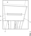
FIG. 1 is a perspective view of a refrigeration appliance of the present disclosure built into cabinetry with a door in the closed position; -
FIG. 2 is a perspective view of the refrigeration appliance ofFIG. 1 , illustrating the door in an open position to reveal a cabinet with a refrigeration compartment; -
FIG. 3 is a perspective view of the refrigeration appliance ofFIG. 1 , illustrating the cabinet including a vacuum-insulated structure; -
FIG. 4 is a front elevational view of the refrigeration appliance ofFIG. 1 ; -
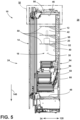
FIG. 5 is an elevational view of a cross-section of the refrigeration appliance ofFIG. 1 taken through line V-V ofFIG. 4 , illustrating the vacuum-insulated structure of the cabinet including an outer wrapper and an inner liner defining at least in part the interior surfaces of the refrigeration compartment; -
FIG. 6 is a magnified view of area VI ofFIG. 5 , illustrating the door of the refrigeration appliance ofFIG. 1 also including a vacuum-insulated structure with an outer wrapper, an inner liner, and a trim breaker coupled to both the outer wrapper and the inner liner; -
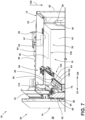
FIG. 7 is the same view asFIG. 6 but from a slight perspective, illustrating the vacuum-insulated structure of the cabinet further including a trim breaker coupled to both the outer wrapper and the inner liner of the vacuum-insulated structure of the cabinet; -
FIG. 8 is a magnified view of area VIII ofFIG. 6 , illustrating (i) the door further including a gasket forming a seal against a forward surface of the cabinet provided by the outer wrapper and (ii) the trim breaker of the vacuum-insulated structure of the door including a projection that extends rearward into the refrigeration compartment of the cabinet and separated from the trim breaker of the vacuum-insulated structure of the cabinet by a gap of relatively small proportions to reduce air flow from deeper within the refrigeration cabinet to the seal (e.g., interface) between the door and the cabinet that the gasket forms; -
FIG. 9 is an elevation view of a cross-section of the refrigeration appliance ofFIG. 1 taken through line IX-IX ofFIG. 4 , illustrating the inner liner of the vacuum-insulated structure of the cabinet providing at least a portion of the interior surfaces defining the refrigeration compartment; -
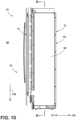
FIG. 10 is a side elevation view of the refrigeration appliance ofFIG. 1 ; -
FIG. 11 is an elevation view of a cross-section of the refrigeration appliance ofFIG. 1 taken through line XI-XI ofFIG. 10 , illustrating the inner liner of the vacuum-insulated structure of the cabinet providing the sidewalls, ceiling, and floor of the refrigeration compartment; -
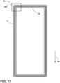
FIG. 12 is an elevation view of the trim breaker of the vacuum-insulated structure of the door; and -
FIG. 13 is a magnified perspective view of area XIII ofFIG. 12 , illustrating the trim breaker of the vacuum-insulated structure of the door further including an outer perimeter, a rear recess inward of the outer perimeter, and the projection inward of the rear recess. - The components in the figures are not necessarily to scale, emphasis instead being placed upon illustrating the principles described herein.
- The present illustrated embodiments reside primarily in combinations of method steps and apparatus components related to a refrigeration appliance. Accordingly, the apparatus components and method steps have been represented, where appropriate, by conventional symbols in the drawings, showing only those specific details that are pertinent to understanding the embodiments of the present disclosure so as not to obscure the disclosure with details that will be readily apparent to those of ordinary skill in the art having the benefit of the description herein. Further, like numerals in the description and drawings represent like elements.
- For purposes of description herein, the terms "upper," "lower," "right," "left," "rear," "front," "vertical," "horizontal," and derivatives thereof shall relate to the disclosure as oriented in
FIG. 1 . Unless stated otherwise, the term "front" shall refer to the surface of the element closer to an intended viewer, and the term "rear" shall refer to the surface of the element further from the intended viewer. However, it is to be understood that the disclosure may assume various alternative orientations, except where expressly specified to the contrary. It is also to be understood that the specific devices and processes illustrated in the attached drawings, and described in the following specification are simply exemplary embodiments of the inventive concepts defined in the appended claims. Hence, specific dimensions and other physical characteristics relating to the embodiments disclosed herein are not to be considered as limiting, unless the claims expressly state otherwise. - The terms "including," "comprises," "comprising," or any other variation thereof, are intended to cover a non-exclusive inclusion, such that a process, method, article, or apparatus that comprises a list of elements does not include only those elements but may include other elements not expressly listed or inherent to such process, method, article, or apparatus. An element preceded by "comprises a ... " does not, without more constraints, preclude the existence of additional identical elements in the process, method, article, or apparatus that comprises the element.
- Referring to
FIGS. 1 and2 , arefrigeration appliance 10 includes acabinet 12 and adoor 14. Thecabinet 12 includes arefrigeration compartment 16 and an opening 18 into therefrigeration compartment 16. Therefrigeration compartment 16 is configured to hold afood item 20. Thedoor 14 is coupled to thecabinet 12, such as throughhinges 22 that are attached to both thedoor 14 and thecabinet 12. Thehinges 22 can be articulating hinges. Thedoor 14 is movable to, from, and between a closed position 24 (see, e.g.,FIG. 1 ) and an open position 26 (see, e.g.,FIG. 2 ). In the closedposition 24, thedoor 14 denies access through the opening 18 and into therefrigeration compartment 16 from anexternal environment 28. In theopen position 26, thedoor 14 allows access through the opening 18 to therefrigeration compartment 16 from theexternal environment 28. Therefrigeration appliance 10 can be a freezer that maintains air and thefood item 20 within therefrigeration compartment 16 at a temperature below a freezing point of water, such as within a range of from -18 °C to -23 °C. Therefrigeration appliance 10 can be a refrigerator that maintains the air and thefood item 20 within therefrigeration compartment 16 at a temperature below room temperature but above the freezing point of water, such as within a range of from 2 °C to 4 °C. Therefrigeration appliance 10 can includemultiple refrigeration compartments 16 that are maintained at difference temperatures (e.g., one of therefrigeration compartments 16 as the freezer and another one of therefrigeration compartments 16 as the refrigerator). Therefrigeration appliance 10 can be of a built-in variety, where thecabinet 12 is designed to be recessed intocabinetry 30, as illustrated. Alternatively, therefrigeration appliance 10 can be of a stand-alone variety, where thecabinet 12 is designed to be seen from theexternal environment 28 and thus may include a wrapper (not illustrated) over thecabinet 12. - Referring additionally to
FIGS. 3-10 , thecabinet 12 provides aforward surface 32. Theforward surface 32 faces forward 34. Theforward surface 32 faces thedoor 14 when thedoor 14 is in the closedposition 24. Theforward surface 32 is substantially vertical. The opening 18 into therefrigeration compartment 16 is disposed laterally inward of theforward surface 32. For example, theforward surface 32 frames theopening 18. Thedoor 14 forms aseal 36 against theforward surface 32 of thecabinet 12, when thedoor 14 is in the closedposition 24, as further discussed below. - The
cabinet 12 includesinterior surfaces 38 that define therefrigeration compartment 16. For example, as in the illustrated embodiments, theinterior surfaces 38 can be those provided by arear wall 40,side walls ceiling 46, and afloor 48 that collectively define therefrigeration compartment 16. Theceiling 46 and thefloor 48 oppose each other. Theside walls rear wall 40 and thedoor 14 oppose each other, when thedoor 14 is in the closedposition 24. Therefrigeration compartment 16 is configured to hold thefood item 20 in terms of the size of therefrigeration compartment 16 being large enough to hold thefood item 20. Further, therefrigeration compartment 16 can include one ormore shelves 50 and the like that provide ahorizontal surface 52 upon which thefood item 20 can sit without falling to thefloor 48 or out of therefrigeration compartment 16 when thedoor 14 is in theopen position 26. - In embodiments, the
cabinet 12 includes a vacuum-insulatedstructure 54. Thecabinet 12 then can include aninner liner 56, anouter wrapper 58, and atrim breaker 60. Theouter wrapper 58 at least partially envelops theinner liner 56. For example, theouter wrapper 58 can include atop section 62 that is disposed above atop section 64 of theinner liner 56, arear section 66 that is rearward of arear section 68 of theinner liner 56, opposingside sections side sections inner liner 56, and so on. In such embodiments, thetop section 64 of theinner liner 56 can form theceiling 46 of therefrigeration compartment 16, therear section 68 of theinner liner 56 can form therear wall 40 of therefrigeration compartment 16, and theside sections 74. 76 of theinner liner 56 can form theside walls refrigeration compartment 16. In addition to at least partially enveloping theinner liner 56, theouter wrapper 58 of vacuum-insulatedstructure 54 can provide theforward surface 32 of thecabinet 12 that forms theseal 36 with thedoor 14, when thedoor 14 is in theclosed position 24. - The
trim breaker 60 is coupled to both theinner liner 56 and theouter wrapper 58. For example, as in the illustrated embodiments, thetrim breaker 60 includes aforward recess 78 and arear recess 80. Theforward recess 78 is disposed forward 34 relative to therear recess 80. Anedge 82 of theouter wrapper 58 of the vacuum-insulatedstructure 54 of thecabinet 12 is disposed within theforward recess 78 of thetrim breaker 60, to couple thetrim breaker 60 and theouter wrapper 58 together. Adhesive (not illustrated) can be utilized to affix thetrim breaker 60 and theouter wrapper 58 in an air-tight manner. Similarly, anedge 84 of theinner liner 56 of the vacuum-insulatedstructure 54 of thecabinet 12 is disposed within therear recess 80 of thetrim breaker 60, to couple thetrim breaker 60 and theinner liner 56 together. Again, adhesive (not illustrated) can be utilized to affix thetrim breaker 60 and theinner liner 56 in an air-tight manner. - The
outer wrapper 58 is separated from theinner liner 56 by aspace 86. Thespace 86 has an air pressure that is less than atmospheric pressure at theexternal environment 28. The reduced pressure relative to theexternal environment 28 is a consequence of evacuating air from thespace 86 after assembly of vacuum-insulatedstructure 54. Reducing the amount of air within thespace 86 reduces thermal transfer through thespace 86. Theouter wrapper 58 and theinner liner 56 of the vacuum-insulatedstructure 54 of thecabinet 12 can be fabricated from sheet metal (either unitary or disparate panels welded together) or a plastic material. Thetrim breaker 60 can be a plastic material. Insulation material 87 (e.g., fumed silica) can occupy thespace 86. - The
door 14 includes a vacuum-insulatedstructure 88. The vacuum-insulatedstructure 88 of thedoor 14 can include aninner liner 90 and anouter wrapper 92. Theinner liner 90 faces therefrigeration compartment 16, more particularly therear wall 40 thereof, when thedoor 14 is in theclosed position 24. Theouter wrapper 92 faces theexternal environment 28 and is disposed forward 34 of theinner liner 90, when thedoor 14 is in theclosed position 24. Theouter wrapper 92 and theinner liner 90 are separated by aspace 94. Like thespace 86 of thecabinet 12, thespace 94 of thedoor 14 has an air pressure that is less than atmospheric pressure at theexternal environment 28. The reduced pressure relative to theexternal environment 28 is a consequence of evacuating air from thespace 94 after assembly of vacuum-insulatedstructure 88. Reducing the amount of air within thespace 94 reduces thermal transfer through thespace 94. Theinner liner 90 and theouter wrapper 92 can be formed of stamped sheet metal or a plastic material. Insulation material 96 (e.g., fumed silica) can occupy thespace 94. - The vacuum-insulated
structure 88 of thedoor 14 further includes atrim breaker 98. Thetrim breaker 98 is coupled to both theinner liner 90 and theouter wrapper 92 of the vacuum-insulatedstructure 88 of thedoor 14. For example, as in the illustrated embodiments, thetrim breaker 98 of thedoor 14 includes an outerforward recess 100 and aninner forward recess 102. The outerforward recess 100 and theinner forward recess 102 are "forward" in the sense that they are open from the forward 34 direction (e.g., away from the refrigeration compartment 16). The outerforward recess 100 is disposed closer to anouter perimeter 104 of thetrim breaker 98 than theinner forward recess 102. Anedge 106 of theouter wrapper 92 of thedoor 14 is disposed within the outerforward recess 100 of thetrim breaker 98, to couple thetrim breaker 98 and theouter wrapper 92 together. Adhesive 108 can be utilized to form an air-tight seal there. Anedge 110 of theinner liner 90 of thedoor 14 is disposed within theinner forward recess 102 of thetrim breaker 98, to couple thetrim breaker 98 and theinner liner 90 together. Likewise, adhesive (not illustrated) can be utilized to form an air-tight seal there. Thetrim breaker 98 can be formed of a plastic material. - The
door 14 further includes agasket 114. Thegasket 114 forms theseal 36 against theforward surface 32 of thecabinet 12 when thedoor 14 is in theclosed position 24. In embodiments where thecabinet 12 includes the vacuum-insulatedstructure 54 with theouter wrapper 58 providing theforward surface 32, thegasket 114 forms theseal 36 against theouter wrapper 58. Thegasket 114 can include a rearward portion 116 with amagnet 118, acentral portion 120, and aforward portion 122. Thecentral portion 120 is disposed between the rearward portion 116 and theforward portion 122. Thegasket 114 can be made of a plastic, aside from themagnet 118. The rearward portion 116 can provide arear surface 124 that is substantially vertical and positioned to interface with and form theseal 36 against theforward surface 32 of the cabinet 12 (e.g., theouter wrapper 58 thereof), when thedoor 14 is in theclosed position 24. Themagnet 118 draws thegasket 114 and thus thedoor 14 to theforward surface 32 of thecabinet 12 to seal 36 thedoor 14 to thecabinet 12. - The
trim breaker 98 of thedoor 14 further includes arear recess 126. Therear recess 126 is open from arearward direction 128. Therear recess 126 is disposed closer to theouter perimeter 104 of thetrim breaker 98 than theinner forward recess 102 of thetrim breaker 98. Therear recess 126 is disposed further from theouter perimeter 104 than the outerforward recess 100 of thetrim breaker 98. Theforward portion 122 of thegasket 114 is disposed within therear recess 126, to couple thetrim breaker 98 and thegasket 114 together. Theforward portion 122 of thegasket 114 can friction fit into therear recess 126 to attach thedoor 14gasket 114 and thetrim breaker 98 together. - The
trim breaker 98 of thedoor 14 further includes aprojection 130. Theprojection 130 extends rearward 128 relative to theinner forward recess 102 and thegasket 114 of thedoor 14. Theprojection 130 extends rearward 128 through theopening 18 of thecabinet 12 and into therefrigeration compartment 16 when thedoor 14 is in theclosed position 24. Theprojection 130 opposes one or more of the interior surfaces 38 of thecabinet 12 that define therefrigeration compartment 16, when thedoor 14 is in theclosed position 24. However, in embodiments, theprojection 130 is separated from the interior surfaces 38 by agap 132. In other words, in those embodiments, theprojection 130 does not contact thecabinet 12. However, in other embodiments, theprojection 130 may contact thecabinet 12. Thegap 132 being present can be advantageous because manufacturing tolerances can cause variations in the dimensions of thecabinet 12 and thedoor 14. Thegap 132 being present allows for such variations to exist without theprojection 130 preventing thedoor 14 from moving to theclosed position 24. - In embodiments, such as those illustrated, the
trim breaker 60 of thecabinet 12 provides one or more of the interior surfaces 38 of thecabinet 12 that define therefrigeration compartment 16. For example, thetrim breaker 60 can form part of theceiling 46 of therefrigeration compartment 16, along with theinner liner 56. In that instance, thetrim breaker 60 forms aforward part 134 of theceiling 46, and theinner liner 56 may form aremainder 136 of theceiling 46 of therefrigeration compartment 16. When thedoor 14 is in theclosed position 24, theprojection 130 of thetrim breaker 98 of thedoor 14 opposes thetrim breaker 60 of thecabinet 12. - The
trim breaker 98 has atop section 138 where theprojection 130 faces theceiling 46 of therefrigeration compartment 16. In embodiments, at thetop section 138, thetrim breaker 98 has a tophorizontal wall 142. A topvertical wall 144 extends downward 146 from the tophorizontal wall 142. A secondhorizontal wall 148 extends forward 34 from the tophorizontal wall 142. A secondvertical wall 150 extends downward 146 from the secondhorizontal wall 148. A thirdhorizontal wall 152 extends forward 34 from the secondvertical wall 150. A fourthhorizontal wall 154 extends forward 34 from the thirdhorizontal wall 152. Thetrim breaker 98 further includes adownward transition 156 from the thirdhorizontal wall 152 to the fourthhorizontal wall 154. A thirdvertical wall 158 extends downward 146 from the fourthhorizontal wall 154. A fifthhorizontal wall 160 extends rearward 128 from the thirdvertical wall 158. Anangled wall 162 extends rearward 128 and downward 146 from the thirdvertical wall 158. A fourthvertical wall 164 extends downward 146 from theangled wall 162. A sixthhorizontal wall 166 extends rearward 128 from the fourthvertical wall 164. - The top
horizontal wall 142, the topvertical wall 144, and the secondhorizontal wall 148 of thetrim breaker 98 define the outerforward recess 100 of thetrim breaker 98 of thedoor 14. As mentioned, theedge 106 of theouter wrapper 92 of thedoor 14 is disposed within the outerforward recess 100 of thetrim breaker 98 of thedoor 14. More particularly, theedge 106 of theouter wrapper 92 is disposed horizontally between the tophorizontal wall 142 and the secondhorizontal wall 148 of thetrim breaker 98 and forward 34 of the topvertical wall 144 of thetrim breaker 98. - The second
horizontal wall 148, the secondvertical wall 150, and the thirdhorizontal wall 152 of thetrim breaker 98 together define therear recess 126 of thetrim breaker 98 of thedoor 14. As mentioned, theforward portion 122 of thegasket 114 of thedoor 14 is disposed within therear recess 126 to couple thetrim breaker 98 and thegasket 114 of thedoor 14 together. Theforward portion 122 of thegasket 114 is disposed rearward 128 of the secondvertical wall 150 and between the secondhorizontal wall 148 and the thirdhorizontal wall 152. - The fourth
horizontal wall 154, the thirdvertical wall 158, and the fifthhorizontal wall 160 together define theinner forward recess 102 of thetrim breaker 98 of thedoor 14. As mentioned, theedge 110 of theinner liner 90 of thedoor 14 is disposed within theinner forward recess 102 to couple theinner liner 90 and thetrim breaker 98 of thedoor 14 together. Theedge 110 is disposed horizontally between the fourthhorizontal wall 154 and the fifthhorizontal wall 160, and forward 34 of the thirdvertical wall 158. - The
angled wall 162, the fourthvertical wall 164, and the sixthhorizontal wall 166 of thetrim breaker 98 together define theprojection 130. As mentioned, theprojection 130 opposes one or more of the interior surfaces 38 of thecabinet 12 that define therefrigeration compartment 16, when thedoor 14 is in theclosed position 24. More particularly, in embodiments, theangled wall 162 of thetrim breaker 98 opposes one or more of the interior surfaces 38 of thecabinet 12 that define therefrigeration compartment 16. - The
gap 132 separating theprojection 130 of thetrim breaker 98 of thedoor 14 from the refrigeration compartment 16 (e.g., theceiling 46, or the portion of theceiling 46 provided by thetrim breaker 60 of the cabinet 12) has ashortest distance 168 between theprojection 130 and the surface of thecabinet 12 defining therefrigeration compartment 16, when thedoor 14 is in theclosed position 24. In embodiments, theshortest distance 168 is less than 12 mm. In embodiments, theshortest distance 168 is within a range of from 4 mm to 12 mm. In other embodiments, theshortest distance 168 is zero (e.g., theprojection 130 contacts the surface of thecabinet 12 defining the refrigeration compartment 16). In embodiments, theprojection 130 extends rearward 128 at least 30 mm from aplane 170 that theforward surface 32 of thecabinet 12 forms. - The
refrigeration appliance 10 of the present disclosure addresses the problem set forth in the background of suboptimally high thermal transfer across the interface (e.g., where theseal 36 is formed) between thedoor 14 and the cabinet 12 (e.g., from theexternal environment 28 through the interface and into the refrigeration compartment 16) because theprojection 130 of thetrim breaker 98 of thedoor 14 extends into therefrigeration compartment 16 and is separated from the cabinet 12 (e.g., thetrim breaker 60 of the vacuum-insulatedstructure 54 of the cabinet 12) by thegap 132 with theshortest distance 168 that is relatively small. Thegap 132 being relatively small hinders air flow from further within therefrigeration compartment 16, through thegap 132, and to thegasket 114 of thedoor 14 interfacing with theforward surface 32 of thecabinet 12. Hindering the air flow hinders thermal transfer across that interface as well as the flow of relatively cool air across the interface and into theexternal environment 28. The reduced thermal transfer results in less electricity that therefrigeration appliance 10 has to consume to maintain the temperature of therefrigeration compartment 16 and thus thefood item 20. - According to a first aspect, a refrigeration appliance comprises: (a) a cabinet comprising (i) a forward surface that is substantially vertical, (ii) interior surfaces defining a refrigeration compartment configured to hold a food item, and (iii) an opening into the refrigeration compartment disposed inward of the forward surface; and (b) a door coupled to the cabinet, the door comprising (i) a closed position that denies access through the opening and into the refrigeration compartment of the cabinet from an external environment, (ii) an open position that allows access through the opening to the refrigeration compartment from the external environment, the door being movable to, from, and between the closed position and the open position, (iii) an inner liner facing the refrigeration compartment when the door is in the closed position, (iv) an outer wrapper separated from the inner liner by a space, and (v) a trim breaker coupled to both the inner liner and the outer wrapper, the trim breaker comprising a projection that extends rearward into the refrigeration compartment of the cabinet, when the door is in the closed position, wherein, the projection of the trim breaker opposes one or more of the interior surfaces of the cabinet defining the refrigeration compartment, when the door is in the closed position but is separated therefrom by a gap.
- According to a second aspect of the present disclosure, the refrigeration appliance of the first aspect is presented, wherein the cabinet further comprises (i) an inner liner, (ii) an outer wrapper at least partially enveloping the inner liner and separated from the inner liner by a space, and (iii) a trim breaker coupled to both the inner liner and the outer wrapper.
- According to a third aspect of the present disclosure, the refrigeration appliance of the second aspect is presented, wherein (i) the outer wrapper provides the forward surface, and (ii) the door further comprises a gasket that forms a seal against the forward surface of the outer wrapper when the door is in the closed position.
- According to a fourth aspect of the present disclosure, the refrigeration appliance of any one of the second through third aspects is presented, wherein the space of the cabinet between the inner liner and the outer wrapper has an air pressure than is less than atmospheric pressure.
- According to a fifth aspect of the present disclosure, the refrigeration appliance of any one of the second through fourth aspects is presented, wherein the trim breaker of the cabinet comprises (i) a forward recess within which an edge of the outer wrapper of the cabinet is disposed to couple the trim breaker and the outer wrapper of the cabinet together and (ii) a rear recess within which an edge of the inner liner of the cabinet is disposed to couple the trim breaker and the inner liner of the cabinet together.
- According to a sixth aspect of the present disclosure, the refrigeration appliance of any one of the second through fifth aspects is presented, wherein the trim breaker of the cabinet provides one or more of the interior surfaces of the cabinet defining the refrigeration compartment that the projection of the trim breaker of the door opposes when the door is in the closed position.
- According to a seventh aspect of the present disclosure, the refrigeration appliance of the sixth aspect is presented, wherein the one or more interior surfaces of the cabinet defining the refrigeration compartment that the trim breaker of the cabinet provides and that the projection of the trim breaker of the door opposes form part of a ceiling of the refrigeration compartment.
- According to an eighth aspect of the present disclosure, the refrigeration appliance of any one of the first through seventh aspects is presented, wherein the space of the door between the inner liner and the outer wrapper has an air pressure that is less than atmospheric pressure.
- According to a ninth aspect of the present disclosure, the refrigeration appliance of any one of the first through eighth aspects is presented, wherein (a) the trim breaker of the door further comprises (i) an outer forward recess within which an edge of the outer wrapper of the door is disposed and (ii) an inner forward recess within which an edge of the inner liner of the door is disposed, the outer forward recess disposed closer to an outer perimeter of the trim breaker than the inner forward recess, and (b) the projection extends rearward relative to the inner forward recess and into the refrigeration compartment of the cabinet.
- According to a tenth aspect of the present disclosure, the refrigeration appliance of the ninth aspect is presented, wherein (i) the trim breaker of the door further comprises a rear recess disposed closer to the outer perimeter than the inner forward recess but further from the outer perimeter than the outer forward recess, and (ii) a forward portion of a gasket of the door is disposed within the rear recess to couple the trim breaker and the gasket together.
- According to an eleventh aspect of the present disclosure, the refrigeration appliance of any one of the first through tenth aspects is presented, wherein the trim breaker of the door further comprises, at a top section thereof, (i) a top horizontal wall, (ii) a top vertical wall that extends downward from the top horizontal wall, (iii) a second horizontal wall that extends forward from the top horizontal wall, (iv) a second vertical wall that extends downward from the second horizontal wall, (v) a third horizontal wall that extends forward from the second vertical wall, (vi) a fourth horizontal wall that extends forward from the third horizontal wall, (vii) a downward transition from the third horizontal wall to the fourth horizontal wall, (viii) a third vertical wall that extends downward from the fourth horizontal wall, (ix) a fifth horizontal wall that extends rearward from the third vertical wall, (x) an angled wall that extends rearward and downward from the third vertical wall, (xi) a fourth vertical wall that extends downward from the angled wall, and (xii) a sixth horizontal wall that extends rearward from the fourth vertical wall.
- According to a twelfth aspect of the present disclosure, the refrigeration appliance of the eleventh aspect is presented, wherein the top horizontal wall, the top vertical wall, and the second horizontal wall define an outer forward recess within which an edge of the outer wrapper of the door is disposed, with the edge of the outer wrapper of the door disposed horizontally between the top horizontal wall and the second horizontal wall and forward of the top vertical wall.
- According to a thirteenth aspect of the present disclosure, the refrigeration appliance of any one of the eleventh through twelfth aspects is presented, wherein the second horizontal wall, the second vertical wall, and the third horizontal wall define a rear recess within which a forward portion of a gasket of the door is disposed to couple the trim breaker and the gasket of the door together.
- According to a fourteenth aspect of the present disclosure, the refrigeration appliance of any one of the eleventh through thirteenth aspects is presented, wherein the fourth horizontal wall, the third vertical wall, and the fifth horizontal wall define an inner forward recess within which an edge of the inner liner of the door is disposed.
- According to a fifteenth aspect of the present disclosure, the refrigeration appliance of any one of the eleventh through fourteenth aspects is presented, wherein the fourth horizontal wall, the third vertical wall, and the fifth horizontal wall define an inner forward recess within which an edge of the inner liner of the door is disposed.
- According to a sixteenth aspect of the present disclosure, the refrigeration appliance of any one of the eleventh through fifteenth aspects is presented, wherein the angled wall of the trim breaker of the door opposes the one or more interior surfaces of the cabinet defining the refrigeration compartment.
- According to a seventeenth aspect of the present disclosure, the refrigeration appliance of any one of the first through sixteenth aspects is presented, wherein the door further comprises a gasket comprising (i) a forward portion coupled to the trim breaker and (ii) a rearward portion that provides a rear surface that is substantially vertical and positioned to interface with and form a seal against the forward surface of the outer wrapper when the door is in the closed position.
- According to an eighteenth aspect of the present disclosure, the refrigeration appliance of the seventeenth aspect is presented, wherein the forward portion of the gasket of the door is disposed within a rear recess of the trim breaker of the door to couple the gasket and the trim breaker together.
- According to a nineteenth aspect of the present disclosure, the refrigeration appliance of any one of the first through eighteenth aspects is presented, wherein the gap has a shortest distance that is less than 12 mm.
- According to a twentieth aspect of the present disclosure, a refrigeration appliance comprises (a) a cabinet comprising a vacuum-insulated structure within which a refrigeration compartment configured to hold a food item is disposed; and (b) a door comprising a vacuum-insulated door structure coupled to the cabinet, the vacuum-insulated door comprising (i) a gasket that forms a seal against the vacuum-insulated cabinet when the door is in a closed position and (ii) a projection inward of the gasket that projects into the refrigeration compartment and is separated from the vacuum-insulated cabinet by a gap, the gap having a shortest distance that is less than 12 mm.
- It will be understood by one having ordinary skill in the art that construction of the described disclosure and other components is not limited to any specific material. Other exemplary embodiments of the disclosure disclosed herein may be formed from a wide variety of materials, unless described otherwise herein.
- For purposes of this disclosure, the term "coupled" (in all of its forms, couple, coupling, coupled, etc.) generally means the joining of two components (electrical or mechanical) directly or indirectly to one another. Such joining may be stationary in nature or movable in nature. Such joining may be achieved with the two components (electrical or mechanical) and any additional intermediate members being integrally formed as a single unitary body with one another or with the two components. Such joining may be permanent in nature or may be removable or releasable in nature unless otherwise stated.
- It is also important to note that the construction and arrangement of the elements of the disclosure as shown in the exemplary embodiments is illustrative only. Although only a few embodiments of the present innovations have been described in detail in this disclosure, those skilled in the art who review this disclosure will readily appreciate that many modifications are possible (e.g., variations in sizes, dimensions, structures, shapes and proportions of the various elements, values of parameters, mounting arrangements, use of materials, colors, orientations, etc.) without materially departing from the novel teachings and advantages of the subject matter recited. For example, elements shown as integrally formed may be constructed of multiple parts or elements shown as multiple parts may be integrally formed, the operation of the interfaces may be reversed or otherwise varied, the length or width of the structures and/or members or connector or other elements of the system may be varied, the nature or number of adjustment positions provided between the elements may be varied. It should be noted that the elements and/or assemblies of the system may be constructed from any of a wide variety of materials that provide sufficient strength or durability, in any of a wide variety of colors, textures, and combinations. Accordingly, all such modifications are intended to be included within the scope of the present innovations. Other substitutions, modifications, changes, and omissions may be made in the design, operating conditions, and arrangement of the desired and other exemplary embodiments without departing from the spirit of the present innovations.
- It will be understood that any described processes or steps within described processes may be combined with other disclosed processes or steps to form structures within the scope of the present disclosure. The exemplary structures and processes disclosed herein are for illustrative purposes and are not to be construed as limiting.
Claims (15)
- A refrigeration appliance (10) comprising:a cabinet (12) comprising (i) a forward surface (32) that is substantially vertical, (ii) interior surfaces (38) defining a refrigeration compartment (16) configured to hold a food item (20), and (iii) an opening (18) into the refrigeration compartment (16) disposed inward of the forward surface (32); anda door (14) coupled to the cabinet (12), the door (14) comprisinga closed position (24) that denies access through the opening (18) and into the refrigeration compartment (16) of the cabinet (12) from an external environment (28),an open position (26) that allows access through the opening (18) to the refrigeration compartment (16) from the external environment (28), the door (14) being movable to, from, and between the closed position (24) and the open position (26),an inner liner (90) facing the refrigeration compartment (16) when the door (14) is in the closed position (24),an outer wrapper (92) separated from the inner liner (90) by a space (94), anda trim breaker (98) coupled to both the inner liner (90) and the outer wrapper (92), the trim breaker (98) comprising a projection (130) that extends rearward (128) into the refrigeration compartment (16) of the cabinet (12), when the door (14) is in the closed position (24),wherein, the projection (130) of the trim breaker (98) opposes one or more of the interior surfaces (38) of the cabinet (12) defining the refrigeration compartment (16), when the door (14) is in the closed position (24) but is separated therefrom by a gap (132).
- The refrigeration appliance (10) of claim 1, wherein
the cabinet (12) further comprises (i) an inner liner (56), (ii) an outer wrapper (58) at least partially enveloping the inner liner (56) and separated from the inner liner (56) by a space (86), and (iii) a trim breaker (60) coupled to both the inner liner (56) and the outer wrapper (58). - The refrigeration appliance (10) of claim 2, wherein
the trim breaker (60) of the cabinet (12) provides one or more of the interior surfaces (38) of the cabinet (12) defining the refrigeration compartment (16) that the projection (130) of the trim breaker (98) of the door (14) opposes when the door (14) is in the closed position (24). - The refrigeration appliance (10) of claim 3, wherein
the one or more interior surfaces (38) of the cabinet (12) defining the refrigeration compartment (16) that the trim breaker (60) of the cabinet (12) provides and that the projection (130) of the trim breaker (98) of the door (14) opposes form part of a ceiling (46) of the refrigeration compartment (16). - The refrigeration appliance (10) of any one of claims 1-4, wherein
the space (94) of the door (14) between the inner liner (90) and the outer wrapper (58) has an air pressure than is less than atmospheric pressure. - The refrigeration appliance (10) of any one of claims 1-5, whereinthe trim breaker (98) of the door (14) further comprises (i) an outer forward recess (100) within which an edge (106) of the outer wrapper (92) of the door (14) is disposed and (ii) an inner forward recess (102) within which an edge (110) of the inner liner (90) of the door (14) is disposed, the outer forward recess (100) disposed closer to an outer perimeter (104) of the trim breaker (98) than the inner forward recess (102), andthe projection (130) extends rearward (128) relative to the inner forward recess (102) and into the refrigeration compartment (16) of the cabinet (12).
- The refrigeration appliance (10) of claim 6, whereinthe trim breaker (98) of the door (14) further comprises a rear recess (126) disposed closer to the outer perimeter (104) than the inner forward recess (102) but further from the outer perimeter (104) than the outer forward recess (100), anda forward portion (122) of a gasket (114) of the door (14) is disposed within the rear recess (126) to couple the trim breaker (98) and the gasket (114) together.
- The refrigeration appliance (10) of any one of claims 1-7, wherein
the trim breaker (98) of the door (14) further comprises, at a top section (138) thereof, (i) a top horizontal wall (142), (ii) a top vertical wall (144) that extends downward (146) from the top horizontal wall (142), (iii) a second horizontal wall (148) that extends forward (34) from the top horizontal wall (142), (iv) a second vertical wall (150) that extends downward (146) from the second horizontal wall (148), (v) a third horizontal wall (152) that extends forward (34) from the second vertical wall (150), (vi) a fourth horizontal wall (154) that extends forward (34) from the third horizontal wall (152), (vii) a downward (146) transition from the third horizontal wall (152) to the fourth horizontal wall (154), (viii) a third vertical wall (158) that extends downward (146) from the fourth horizontal wall (154), (ix) a fifth horizontal wall (160) that extends rearward (128) from the third vertical wall (158), (x) an angled wall (162) that extends rearward (128) and downward (146) from the third vertical wall (158), (xi) a fourth vertical wall (164) that extends downward (146) from the angled wall (162), and (xii) a sixth horizontal wall (166) that extends rearward (128) from the fourth vertical wall (164). - The refrigeration appliance (10) of claim 8, wherein
the top horizontal wall (142), the top vertical wall (144), and the second horizontal wall (148) define an outer forward recess (100) within which an edge (106) of the outer wrapper (92) of the door (14) is disposed, with the edge (106) of the outer wrapper (92) of the door (14) disposed horizontally between the top horizontal wall (142) and the second horizontal wall (148) and forward (34) of the top vertical wall (144). - The refrigeration appliance (10) of any one of claims 8-9, whereinthe second horizontal wall (148), the second vertical wall (150), and the third horizontal wall (152) define a rear recess (126) within which a forward portion (122) of a gasket (114) of the door (14) is disposed to couple the trim breaker (98) and the gasket (114) of the door (14) together, andthe fourth horizontal wall (154), the third vertical wall (158), and the fifth horizontal wall (160) define an inner forward recess (102) within which an edge (110) of the inner liner (90) of the door (14) is disposed.
- The refrigeration appliance (10) of any one of claims 8-10, wherein
the angled wall (162), the fourth vertical wall (164), and the sixth horizontal wall (166) define the projection (130). - The refrigeration appliance (10) of any one of claims 8-11, wherein
the angled wall (162) of the trim breaker (98) of the door (14) opposes the one or more interior surfaces (38) of the cabinet (12) defining the refrigeration compartment (16). - The refrigeration appliance (10) of any one of claims 1-12, wherein
the door (14) further comprises a gasket (114) comprising (i) a forward portion (122) coupled to the trim breaker (98) and (ii) a rearward portion (116) that provides a rear surface (124) that is substantially vertical and positioned to interface with and form a seal (36) against the forward surface (32) of the outer wrapper (58) when the door (14) is in the closed position (24). - The refrigeration appliance (10) of claim 13, wherein
the forward portion (122) of the gasket (114) of the door (14) is disposed within a rear recess (126) of the trim breaker (98) of the door (14) to couple the gasket (114) and the trim breaker (98) together. - The refrigeration appliance (10) of any one of claims 1-14, wherein
the gap (132) has a shortest distance (168) that is less than 12 mm.
Applications Claiming Priority (1)
| Application Number | Priority Date | Filing Date | Title |
|---|---|---|---|
| US18/224,928 US12398947B2 (en) | 2023-07-21 | 2023-07-21 | Refrigeration appliance with a door projection to reduce thermal transfer at door and cabinet interface |
Publications (1)
| Publication Number | Publication Date |
|---|---|
| EP4495517A1 true EP4495517A1 (en) | 2025-01-22 |
Family
ID=91959303
Family Applications (1)
| Application Number | Title | Priority Date | Filing Date |
|---|---|---|---|
| EP24189466.6A Withdrawn EP4495517A1 (en) | 2023-07-21 | 2024-07-18 | Refrigeration appliance with a door projection to reduce thermal transfer at door and cabinet interface |
Country Status (3)
| Country | Link |
|---|---|
| US (1) | US12398947B2 (en) |
| EP (1) | EP4495517A1 (en) |
| CN (1) | CN119334032A (en) |
Citations (5)
| Publication number | Priority date | Publication date | Assignee | Title |
|---|---|---|---|---|
| US2345743A (en) * | 1941-03-06 | 1944-04-04 | Sunbeam Electric Mfg Company | Refrigerator gasket |
| JPS613387U (en) * | 1984-06-12 | 1986-01-10 | 三菱電機株式会社 | refrigerator |
| KR20030094550A (en) * | 2002-06-04 | 2003-12-18 | 엘지전자 주식회사 | Heat isolation refrigerator |
| US20090007587A1 (en) * | 2005-12-10 | 2009-01-08 | Thomas Lanzl | Freezer door subassembly and freezer with a freezer door subassembly of this type |
| JP2012202582A (en) * | 2011-03-24 | 2012-10-22 | Sanyo Electric Co Ltd | Cooling storage |
Family Cites Families (17)
| Publication number | Priority date | Publication date | Assignee | Title |
|---|---|---|---|---|
| GB725546A (en) | 1952-12-11 | 1955-03-02 | Gen Electric | Improvements in thermally insulated cabinets |
| US3359053A (en) | 1966-01-17 | 1967-12-19 | Gen Electric | Refrigerator door seal |
| US4469383A (en) | 1982-05-20 | 1984-09-04 | General Electric Company | Refrigerator cabinet and method of construction |
| US4653819A (en) | 1985-05-30 | 1987-03-31 | General Electric Company | Refrigerator cabinet and gasket construction |
| US4916864A (en) | 1989-05-05 | 1990-04-17 | White Consolidated Industries, Inc. | Snap-in gasket system for refrigerator and freezer doors |
| US5533311A (en) * | 1994-09-30 | 1996-07-09 | Maytag Corporation | Thermoformed plastic refrigerator door |
| KR100554287B1 (en) | 1999-08-26 | 2006-02-24 | 삼성전자주식회사 | Intermediate bulkhead cover device of parallel refrigerator |
| US7147292B2 (en) * | 2002-06-04 | 2006-12-12 | Lg Electronics Inc. | Obturator for refrigerator |
| GB2440690B (en) | 2005-04-08 | 2009-01-14 | Lg Electronics Inc | Sealing structure of refrigerator |
| US11994336B2 (en) * | 2015-12-09 | 2024-05-28 | Whirlpool Corporation | Vacuum insulated structure with thermal bridge breaker with heat loop |
| US10807298B2 (en) * | 2015-12-29 | 2020-10-20 | Whirlpool Corporation | Molded gas barrier parts for vacuum insulated structure |
| US10753669B2 (en) * | 2016-05-03 | 2020-08-25 | Whirlpool Corporation | Hinge support assembly for a vacuum insulated appliance cabinet |
| US11320193B2 (en) * | 2016-07-26 | 2022-05-03 | Whirlpool Corporation | Vacuum insulated structure trim breaker |
| US10563905B1 (en) * | 2018-09-13 | 2020-02-18 | Whirlpool Corporation | Ferromagnetic cover for a trim breaker of an appliance cabinet |
| US10837697B2 (en) * | 2018-10-31 | 2020-11-17 | Whirlpool Corporation | Polymer trim breaker having gas-blocking flakes and an epoxy coating |
| US11346596B2 (en) | 2019-12-30 | 2022-05-31 | Whirpool Corporation | Trim breaker for an insulated appliance |
| US11898791B2 (en) * | 2020-05-08 | 2024-02-13 | Whirlpool Corporation | Appliance door gasket assembly |
-
2023
- 2023-07-21 US US18/224,928 patent/US12398947B2/en active Active
-
2024
- 2024-07-18 EP EP24189466.6A patent/EP4495517A1/en not_active Withdrawn
- 2024-07-19 CN CN202410972723.1A patent/CN119334032A/en active Pending
Patent Citations (5)
| Publication number | Priority date | Publication date | Assignee | Title |
|---|---|---|---|---|
| US2345743A (en) * | 1941-03-06 | 1944-04-04 | Sunbeam Electric Mfg Company | Refrigerator gasket |
| JPS613387U (en) * | 1984-06-12 | 1986-01-10 | 三菱電機株式会社 | refrigerator |
| KR20030094550A (en) * | 2002-06-04 | 2003-12-18 | 엘지전자 주식회사 | Heat isolation refrigerator |
| US20090007587A1 (en) * | 2005-12-10 | 2009-01-08 | Thomas Lanzl | Freezer door subassembly and freezer with a freezer door subassembly of this type |
| JP2012202582A (en) * | 2011-03-24 | 2012-10-22 | Sanyo Electric Co Ltd | Cooling storage |
Also Published As
| Publication number | Publication date |
|---|---|
| US12398947B2 (en) | 2025-08-26 |
| US20250027705A1 (en) | 2025-01-23 |
| CN119334032A (en) | 2025-01-21 |
Similar Documents
| Publication | Publication Date | Title |
|---|---|---|
| CN102261470B (en) | Sealing system and there are the household electrical appliance of this sealing system | |
| US11898790B2 (en) | Trim breaker for an insulated appliance | |
| KR20160084020A (en) | Refrigerator and display unit of a refrigerator | |
| JP6695151B2 (en) | Showcase door | |
| JPH1096584A (en) | Insulation mechanism of refrigerator | |
| US12398947B2 (en) | Refrigeration appliance with a door projection to reduce thermal transfer at door and cabinet interface | |
| US12313332B2 (en) | Appliance trim breaker | |
| US20250044016A1 (en) | Support system for a vacuum insulated panel | |
| JP2006177653A (en) | refrigerator | |
| CN102261794B (en) | Household electrical appliance | |
| CN102261785B (en) | Low-pressure storage unit for refrigeration appliance and refrigeration appliance | |
| JP6532364B2 (en) | Display door | |
| US12320577B2 (en) | Refrigerator cabinet with a trim breaker and vacuum insulated panel associated with the trim breaker | |
| JP2001317863A (en) | Refrigerator | |
| US20250341359A1 (en) | Trim breaker profile for a vacuum insulated structure | |
| CN203274396U (en) | Cold storage | |
| CN102261782B (en) | Refrigerating appliance | |
| CN219693679U (en) | Sealed drawer for refrigerator | |
| JP2008175467A (en) | refrigerator | |
| CN214365788U (en) | Combined sealing strip and refrigerator | |
| US20260126239A1 (en) | Wall panel assembly for a vacuum insulated appliance | |
| US12535260B2 (en) | Trimbreaker ladder cover | |
| CN219550949U (en) | Refrigerating appliance | |
| CN220436853U (en) | Refrigerating appliance | |
| US20250027703A1 (en) | Refrigeration appliance with conduit system in fluid communication with both refrigeration compartment and freezer compartment |
Legal Events
| Date | Code | Title | Description |
|---|---|---|---|
| PUAI | Public reference made under article 153(3) epc to a published international application that has entered the european phase |
Free format text: ORIGINAL CODE: 0009012 |
|
| STAA | Information on the status of an ep patent application or granted ep patent |
Free format text: STATUS: THE APPLICATION HAS BEEN PUBLISHED |
|
| AK | Designated contracting states |
Kind code of ref document: A1 Designated state(s): AL AT BE BG CH CY CZ DE DK EE ES FI FR GB GR HR HU IE IS IT LI LT LU LV MC ME MK MT NL NO PL PT RO RS SE SI SK SM TR |
|
| STAA | Information on the status of an ep patent application or granted ep patent |
Free format text: STATUS: THE APPLICATION HAS BEEN WITHDRAWN |
|
| 18W | Application withdrawn |
Effective date: 20250409 |