EP4495490A1 - Luftkanalstruktur und klimaanlage damit - Google Patents
Luftkanalstruktur und klimaanlage damit Download PDFInfo
- Publication number
- EP4495490A1 EP4495490A1 EP22931746.6A EP22931746A EP4495490A1 EP 4495490 A1 EP4495490 A1 EP 4495490A1 EP 22931746 A EP22931746 A EP 22931746A EP 4495490 A1 EP4495490 A1 EP 4495490A1
- Authority
- EP
- European Patent Office
- Prior art keywords
- air duct
- section
- air
- structure according
- bending angle
- Prior art date
- Legal status (The legal status is an assumption and is not a legal conclusion. Google has not performed a legal analysis and makes no representation as to the accuracy of the status listed.)
- Pending
Links
Images


Classifications
-
- F—MECHANICAL ENGINEERING; LIGHTING; HEATING; WEAPONS; BLASTING
- F24—HEATING; RANGES; VENTILATING
- F24F—AIR-CONDITIONING; AIR-HUMIDIFICATION; VENTILATION; USE OF AIR CURRENTS FOR SCREENING
- F24F1/00—Room units for air-conditioning, e.g. separate or self-contained units or units receiving primary air from a central station
- F24F1/0007—Indoor units, e.g. fan coil units
- F24F1/0018—Indoor units, e.g. fan coil units characterised by fans
- F24F1/0033—Indoor units, e.g. fan coil units characterised by fans having two or more fans
-
- F—MECHANICAL ENGINEERING; LIGHTING; HEATING; WEAPONS; BLASTING
- F24—HEATING; RANGES; VENTILATING
- F24F—AIR-CONDITIONING; AIR-HUMIDIFICATION; VENTILATION; USE OF AIR CURRENTS FOR SCREENING
- F24F1/00—Room units for air-conditioning, e.g. separate or self-contained units or units receiving primary air from a central station
- F24F1/0007—Indoor units, e.g. fan coil units
- F24F1/0011—Indoor units, e.g. fan coil units characterised by air outlets
- F24F1/0014—Indoor units, e.g. fan coil units characterised by air outlets having two or more outlet openings
-
- F—MECHANICAL ENGINEERING; LIGHTING; HEATING; WEAPONS; BLASTING
- F24—HEATING; RANGES; VENTILATING
- F24F—AIR-CONDITIONING; AIR-HUMIDIFICATION; VENTILATION; USE OF AIR CURRENTS FOR SCREENING
- F24F1/00—Room units for air-conditioning, e.g. separate or self-contained units or units receiving primary air from a central station
- F24F1/0007—Indoor units, e.g. fan coil units
- F24F1/0018—Indoor units, e.g. fan coil units characterised by fans
- F24F1/0022—Centrifugal or radial fans
-
- F—MECHANICAL ENGINEERING; LIGHTING; HEATING; WEAPONS; BLASTING
- F24—HEATING; RANGES; VENTILATING
- F24F—AIR-CONDITIONING; AIR-HUMIDIFICATION; VENTILATION; USE OF AIR CURRENTS FOR SCREENING
- F24F13/00—Details common to, or for air-conditioning, air-humidification, ventilation or use of air currents for screening
- F24F13/02—Ducting arrangements
- F24F13/0236—Ducting arrangements with ducts including air distributors, e.g. air collecting boxes with at least three openings
-
- F—MECHANICAL ENGINEERING; LIGHTING; HEATING; WEAPONS; BLASTING
- F24—HEATING; RANGES; VENTILATING
- F24F—AIR-CONDITIONING; AIR-HUMIDIFICATION; VENTILATION; USE OF AIR CURRENTS FOR SCREENING
- F24F13/00—Details common to, or for air-conditioning, air-humidification, ventilation or use of air currents for screening
- F24F13/24—Means for preventing or suppressing noise
-
- F—MECHANICAL ENGINEERING; LIGHTING; HEATING; WEAPONS; BLASTING
- F24—HEATING; RANGES; VENTILATING
- F24F—AIR-CONDITIONING; AIR-HUMIDIFICATION; VENTILATION; USE OF AIR CURRENTS FOR SCREENING
- F24F1/00—Room units for air-conditioning, e.g. separate or self-contained units or units receiving primary air from a central station
- F24F1/0007—Indoor units, e.g. fan coil units
- F24F1/0043—Indoor units, e.g. fan coil units characterised by mounting arrangements
- F24F1/005—Indoor units, e.g. fan coil units characterised by mounting arrangements mounted on the floor; standing on the floor
-
- Y—GENERAL TAGGING OF NEW TECHNOLOGICAL DEVELOPMENTS; GENERAL TAGGING OF CROSS-SECTIONAL TECHNOLOGIES SPANNING OVER SEVERAL SECTIONS OF THE IPC; TECHNICAL SUBJECTS COVERED BY FORMER USPC CROSS-REFERENCE ART COLLECTIONS [XRACs] AND DIGESTS
- Y02—TECHNOLOGIES OR APPLICATIONS FOR MITIGATION OR ADAPTATION AGAINST CLIMATE CHANGE
- Y02E—REDUCTION OF GREENHOUSE GAS [GHG] EMISSIONS, RELATED TO ENERGY GENERATION, TRANSMISSION OR DISTRIBUTION
- Y02E10/00—Energy generation through renewable energy sources
- Y02E10/70—Wind energy
- Y02E10/72—Wind turbines with rotation axis in wind direction
Definitions
- the present invention belongs to a technical field of air conditioners, and specifically relates to an air duct structure and an air conditioner with the air duct structure.
- an air outlet power source is generally a centrifugal fan, an axial flow fan, and a cross-flow fan.
- a centrifugal fan is generally used as a power output, and more than two centrifugal fans are generally disposed in the air conditioner.
- problems such as large bending and twisting of the flow channel, high resistance of the flow channel, the air flow impacting the wall surface of the flow channel, and poor sound quality of the noise tend to occur.
- the main purpose of the present invention is to provide an air duct structure and air conditioner with the air duct structure, so as to solve the problem of high flow resistance of the air duct structure in some embodiments.
- an air duct structure including a first air duct portion and a second air duct portion, the first air duct portion is provided with a first air duct, the first air duct is provided with a first fan installation cavity for installing a first fan, the second air duct portion is provided with a second air duct, the second air duct is provided with a second fan installation cavity for installing a second fan, characterized in that: a first plane where a central line of the first fan installation cavity is located is disposed in parallel with a second plane where a central line of the second fan installation cavity is located, and a distance between the first plane and the second plane is H, wherein a value range of H is 630mm ⁇ H ⁇ 570mm; wherein the central line of the first fan installation cavity coincides with a rotation axis of an impeller part of the first fan, and the central line of the second fan installation cavity coincides with a rotation axis of an impeller part of the second fan
- the second air duct portion includes a second upper air duct section, a second transition section, and a second lower air duct section which are sequentially connected, and a bending angle between the second transition section and the second upper air duct section is ⁇ ;or a bending angle between the second transition section and the second lower air duct section is ⁇ , or each of a bending angle between the second transition section and the second upper air duct section and a bending angle between the second transition section and the second lower air duct section is ⁇ ; wherein a value range of ⁇ is 16degrees ⁇ 0degrees.
- the air duct structure has an air inlet, and at least a portion of the first upper air duct section is located at one side of the first lower air duct section along an air inlet direction of the air inlet.
- the air duct structure has an air inlet, and at least a portion of the second upper air duct section is located at one side of the second lower air duct section along an air inlet direction of an air inlet.
- the air duct structure has an air inlet, projections of at least a portion of the first air duct portion in a predetermined vertical plane and projections of at least a portion of the second air duct portion in the predetermined vertical plane are overlapped; and the predetermined vertical plane is perpendicular to an air inlet direction of the air inlet.
- the air duct structure has an air inlet
- the first air duct portion has a tapered portion
- the tapered portion is connected with an end of the first lower air duct section away from the first transition section
- the bottom of the second lower air duct section and the tapered portion are disposed in an air inlet direction of the air inlet and spliced together to form a lower air outflow transition portion
- a width C of an air flow circulation section of the lower air outflow transition portion in the air inlet direction of the air inlet has a value range of 0.9 * A + B ⁇ C ⁇ 0 .8* A + B .
- a value range of a width A of an air flow circulation section of the second lower air duct section in a predetermined direction is 80mm to 120mm.
- a value range of the width B of an air flow circulation section of the first lower air duct section in a predetermined direction is 60mm to 90mm.
- a width A of an air flow circulation section of the second lower air duct section in a predetermined direction is greater than a width B of an air flow circulation section of the first lower air duct section in the predetermined direction; the air duct structure has an air inlet, and the predetermined direction is parallel to an air inlet direction of the air inlet.
- the second air duct portion is provided with a second lower air duct section, and a part of an air duct section of the first lower air duct section and a part of an air duct section of the second lower air duct section are separated by a partition plate body portion which is common by the first lower air duct section and the second lower air duct section; a length of the partition plate body portion in a vertical direction is L 1 , wherein a value range of L 1 is 460mm ⁇ L 1 ⁇ 380mm.
- the partition plate body portion is provided with a connected opening for connecting the first air duct portion with the second air duct portion.
- a length of the connected opening in the vertical direction is L 2
- a value range of L 2 is 0.8*L 1 ⁇ L 2 ⁇ 0.5*L 1 .
- a stop plate is disposed in the connected opening, and the stop plate is spaced apart from a top end and a bottom end of the connected opening.
- a length of the stop plate in the vertical direction is p; wherein 120mm ⁇ p ⁇ 100mm.
- a vertical distance between a bottom end of the stop plate and the bottom end of the connected opening is q; wherein 80mm ⁇ q ⁇ 40mm.
- an air flow circulation section of the first lower air duct section located at the partition plate body portion is S 1
- both the first fan installation cavity and the second fan installation cavity have air outlets, and a width of an air outlet of the first fan installation cavity is equal to a width of an air outlet of the second fan installation cavity; wherein a width direction of the air outlet of the first fan installation cavity and a width direction of the air outlet of the second fan installation cavity are a distribution direction of the first air duct portion and the second air duct portion.
- a value of H is 600mm.
- At least a portion of the first air duct portion and at least a portion of the second air duct portion are overlapped with each other in a predetermined direction, and a width A of an air duct cavity of the second air duct portion in the predetermined direction is 100mm.
- At least a portion of the first air duct portion and at least a portion of the second air duct portion are overlapped with each other in a predetermined direction, and a width B of an air duct cavity of the first air duct portion in the predetermined direction is 74mm.
- At least a portion of the first air duct portion and at least a portion of the second air duct portion are overlapped with each other in a predetermined direction, and a width C of the overlapped portion of the first air duct portion and the second air duct portion is 175mm.
- a partition plate body portion is disposed at an overlapping portion of the first air duct portion and the second air duct portion, the partition plate body portion is common by the first air duct portion and the second air duct portion, wherein, a length of the partition plate body portion in a vertical direction is L 1 , wherein L 1 is 440mm.
- an air conditioner including a housing and an air duct structure disposed in the housing, wherein, the air duct structure is the air duct structure described above.
- the air duct structure of the present invention including a first air duct portion and a second air duct portion, the first air duct portion is provided with a first air duct, the first air duct is provided with a first fan installation cavity for installing a first fan, the second air duct portion is provided with a second air duct, the second air duct is provided with a second fan installation cavity for installing a second fan, wherein a first plane where a central line of the first fan installation cavity is located is disposed in parallel with a second plane where a central line of the second fan installation cavity is located, and a distance between the first plane and the second plane is H, wherein a value range of H is 630mm ⁇ H ⁇ 570mm; wherein the central line of the first fan installation cavity coincides with a rotation axis of an impeller part of the first fan, and the central line of the second fan installation cavity coincides with a rotation axis of an impeller part of the second fan; wherein the first air duct portion includes
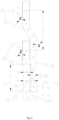
- first air duct portion 100, first air duct; 110. first fan; 101, first fan installation cavity; 11, first upper air duct section;12, first transition section; 13, first lower air duct section; 130, first outlet; 20, second air duct portion; 200, second air duct; 14, tapered portion; 140, lower air outflow transition portion; 210, second fan; 201, second fan installation cavity; 21, second upper air duct section; 22, second transition section;23, second lower air duct section; 230, second outlet; 30, partition plate body portion; 300, connected opening; 301, stop plate; 40, air inlet.
- a cabinet air conditioner is subject to shape restrictions, most of the flow ducts thereof are designed to use flow ducts discharging air in parallel, and the fans are distributed vertically, because the lengths of the air outflow ducts are different and the air outflow areas are different, the flow velocities of the air outflow ducts are different, thus, different pressure differences are generated on the two sides of the flow duct wall shared by the flow ducts, and the air flow is not stable, this will cause the walls to vibrate, causing an aerodynamic noise abnormal sound like a 'drum sound'.
- the present invention provides an air duct structure, which including a first air duct portion 10 and a second air duct portion 20, the first air duct portion 10 is provided with a first air duct 100, the first air duct 100 is provided with a first fan installation cavity 101 for installing a first fan 110, the second air duct portion 20 is provided with a second air duct 200, the second air duct 200 is provided with a second fan installation cavity 201 for installing a second fan 210, characterized in that: a first plane where a central line of the first fan installation cavity 101 is located is disposed in parallel with a second plane where a central line of the second fan installation cavity 201 is located, and a distance between the first plane and the second plane is H, wherein a value range of H is 630mm ⁇ H ⁇ 570mm; wherein the central line of the first fan installation cavity 101 coincides with a rotation axis of an impeller part of the first fan 110, and the central line of the second fan installation cavity 201 coincides
- the air duct structure in the present invention including a first air duct portion 10 and a second air duct portion 20, the first air duct portion 10 is provided with a first air duct 100, the first air duct 100 is provided with a first fan installation cavity 101 for installing a first fan 110, the second air duct portion 20 is provided with a second air duct 200, the second air duct 200 is provided with a second fan installation cavity 201 for installing a second fan 210, characterized in that: a first plane where a central line of the first fan installation cavity 101 is located is disposed in parallel with a second plane where a central line of the second fan installation cavity 201 is located, and a distance between the first plane and the second plane is H, wherein a value range of H is 630mm ⁇ H ⁇ 570mm; wherein the central line of the first fan installation cavity 101 coincides with a rotation axis of an impeller part of the first fan 110, and the central line of the second fan installation cavity 201 coincides with a rotation axis of an impeller part of
- the second air duct portion 20 includes a second upper air duct section 21, a second transition section 22, and a second lower air duct section 23 which are sequentially connected, and a bending angle between the second transition section 22 and the second upper air duct section 21 is ⁇ ;or a bending angle between the second transition section 22 and the second lower air duct section 23 is ⁇ , or each of a bending angle between the second transition section 22 and the second upper air duct section 21 and a bending angle between the second transition section 22 and the second lower air duct section 23 is ⁇ ; wherein a value range of ⁇ is 16degrees ⁇ 0degrees.
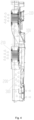
- an angle of the bending angle ⁇ is too large, a structure of the second air duct portion 20 in a width direction of the second air duct portion 20 is not compact enough, and a flow resistance of the second air duct is increased, and the air outflow volume is reduced; if the angle of the bending angle ⁇ is too small, the length of the direct current section of the air duct will be short in the case that the height of the main body of the air conditioner indoor unit is not changed, which is adverse to the circulation of air and the disposition of the two parallel air ducts.
- the layout of fan air duct is further ensured to be compact, the flow resistance of the first air duct 100 and a flow resistance of the second air duct 200 is reduced at the same time, and the air outflow volume is improved.
- the air duct structure is applied to an air duct design of a distributed air supply cabinet type air conditioner having a double centrifugal fan.
- the air duct structure has an air inlet 40, and at least a portion of the first upper air duct section 11 is located at one side of the first lower air duct section 13 along an air inlet direction of the air inlet 40.
- the air duct structure has an air inlet 40, and at least a portion of the second upper air duct section 21 is located at one side of the second lower air duct section 23 along an air inlet direction of an air inlet 40.
- the air duct structure has an air inlet 40, projections of at least a portion of the first air duct portion 10 in a predetermined vertical plane and projections of at least a portion of the second air duct portion 20 in the predetermined vertical plane are overlapped; and the predetermined vertical plane is perpendicular to an air inlet direction of the air inlet 40.
- the air duct structure has an air inlet 40
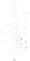
- the first air duct portion 10 has a tapered portion 14, and the tapered portion 14 is connected with an end of the first lower air duct section 13 away from the first transition section 12;
- the bottom of the second lower air duct section 23 and the tapered portion 14 are disposed in an air inlet direction of the air inlet 40 and spliced together to form a lower air outflow transition portion 140
- a width C of an air flow circulation section of the lower air outflow transition portion 140 in the air inlet direction of the air inlet 40 has a value range of 0.9*(A+B) ⁇ C ⁇ 0.8*(A+B).
- a value range of a width A of an air flow circulation section of the second lower air duct section 23 in a predetermined direction is 80mm to 120mm; and/or a value range of the width B of an air flow circulation section of the first lower air duct section 13 in a predetermined direction is 60mm to 90mm; and/or in a same horizontal plane, a width A of an air flow circulation section of the second lower air duct section 23 in a predetermined direction is greater than a width B of an air flow circulation section of the first lower air duct section 13 in the predetermined direction; the air duct structure has an air inlet 40, and the predetermined direction is parallel to an air inlet direction of the air inlet 40.
- the second air duct portion 20 is provided with a second lower air duct section 23, and a part of an air duct section of the first lower air duct section 13 and a part of an air duct section of the second lower air duct section 23 are separated by a partition plate body portion 30 which is common by the first lower air duct section 13 and the second lower air duct section 23; a length of the partition plate body portion 30 in a vertical direction is L 1 , wherein a value range of L 1 is 460mm ⁇ L 1 ⁇ 380mm.
- the partition plate body portion 30 is provided with a connected opening 300 for connecting the first air duct portion 10 with the second air duct portion 20.
- a length of the connected opening 300 in the vertical direction is L 2
- a value range of L 2 is 0.8*L 1 ⁇ L 2 ⁇ 0.5*L 1 .
- a stop plate 301 is disposed in the connected opening 300, and the stop plate 301 is spaced apart from a top end and a bottom end of the connected opening 300.
- a length of the stop plate 301 in the vertical direction is p; wherein 120mm ⁇ p ⁇ 100mm; and/or a vertical distance between a bottom end of the stop plate 301 and the bottom end of the connected opening 300 is q; wherein 80mm ⁇ q ⁇ 40mm.
- an air flow circulation section of the first lower air duct section 13 located at the partition plate body portion 30 is S 1
- both the first fan installation cavity 101 and the second fan installation cavity 201 have air outlets, and a width of an air outlet of the first fan installation cavity 101 is equal to a width of an air outlet of the second fan installation cavity 201; wherein a width direction of the air outlet of the first fan installation cavity 101 and a width direction of the air outlet of the second fan installation cavity 201 are a distribution direction of the first air duct portion 10 and the second air duct portion 20.
- the width of the air outlet of the first fan installation cavity 101 is slightly different from the width of the air outlet of the second fan installation cavity 201.
- the air duct structure further includes a first outlet 130 and a second outlet 230, wherein the first outlet 130 is connected with the first air duct 100, the first outlet 130 is provided at the end of the first lower air duct section 13, the second outlet 230 is connected with the second air duct 200, and the second outlet 230 is provided at the end of the second lower air duct section 23; the width of the first outlet 130 is equal to that of the second outlet 230, the width direction of the first outlet 130 and the width direction of the second outlet 230 are both the extending direction of the air duct structure.
- At least a portion of the first air duct portion 10 and at least a portion of the second air duct portion 20 are overlapped with each other in a predetermined direction, and a width A of an air duct cavity of the second air duct portion 20 in the predetermined direction is 100mm; and/or a width B of an air duct cavity of the first air duct portion 10 in the predetermined direction is 74mm, and/or a width C of the overlapped portion of the first air duct portion 10 and the second air duct portion 20 is 175mm.
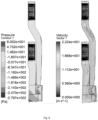
- the flow resistance of the first air duct 100 is relatively large, an air outflow dynamic pressure of the first fan 110 is mostly converted into static pressure, which causes a relatively large air speed loss, resulting in a relatively high static pressure and a relatively small dynamic pressure.
- the second fan 210 has no large resistance to air outflow, so that an air speed is high, the air flow dynamic pressure is large, the air flow static pressure is small.
- the first air duct 100 is connected with the second air duct 200.
- the side with a high static pressure pushes the air to the side with a low static pressure, and the flow direction of the air flow changes, so as to balance the pressures on the two sides, reduce the vortex flow, reduce the flow resistance, increase an air volume, and also make the air outflow volumes of the first outlet 130 and the second outlet 230 approximately consistent.
- both the dynamic pressure and the static pressure in the first air duct 100 and the second air duct 200 become stable, so that the overall aerodynamic noise is significantly improved.
- the distance H between the first fan 110 and the second fan 210 is 600 mm
- the bending angle ⁇ of the first transition section 12 is 30degrees
- the bending angle ⁇ of the second transition section 22 is 14degrees
- a width A of the second air duct 100 is 100mm
- a width B of the first air duct 100 is 74mm
- a width C of the air outlet duct is 175mm
- a length L 1 of a shared wall of the first duct and the second duct is equal to 440mm
- a length L 2 of a duct connected opening is equal to 330mm
- a L 2 section can also be divided into two sections of connected sections, in which a height from the bottom partition position is q, 80mm ⁇ q ⁇ 40mm, providing a partition plate with a length of p at the bottom
- the present invention further provides an air conditioner, including a housing and an air duct structure disposed in the housing, wherein, the air duct structure is the air duct structure described above.
- the design method can not only reduce the flow resistance, but also increase the volume of air discharged,
- the pressure in the air outflow channels can also be self-balanced, so that the air flow pressure and static pressure transition between different channels is smoother, thus, an effect of an balancing air pressure difference of each flow channel is achieved, the aerodynamic noise is smaller, and sound quality is better.
- the air duct structure in the present invention including a first air duct portion 10 and a second air duct portion 20, the first air duct portion 10 is provided with a first air duct 100, the first air duct 100 is provided with a first fan installation cavity 101 for installing a first fan 110, the second air duct portion 20 is provided with a second air duct 200, the second air duct 200 is provided with a second fan installation cavity 201 for installing a second fan 210, characterized in that: a first plane where a central line of the first fan installation cavity 101 is located is disposed in parallel with a second plane where a central line of the second fan installation cavity 201 is located, and a distance between the first plane and the second plane is H, wherein a value range of H is 630mm ⁇ H ⁇ 570mm; wherein the central line of the first fan installation cavity 101 coincides with a rotation axis of an impeller part of the first fan 110, and the central line
- the second air duct portion 20 includes a second upper air duct section 21, a second transition section 22, and a second lower air duct section 23 which are sequentially connected, and the bending angle between the second transition section 22 and the second upper air duct section 21 is ⁇ ;or the bending angle between the second transition section 22 and the second lower air duct section 23 is ⁇ , or both the bending angle between the second transition section 22 and the second upper air duct section 21 and the bending angle between the second transition section 22 and the second lower air duct section 23 are ⁇ ;wherein the value range of ⁇ is 16degrees ⁇ 0degrees.
- an angle of the bending angle ⁇ is too large, a structure of the second air duct portion 20 in a width direction of the second air duct portion 20 is not compact enough, and a flow resistance of the second air duct is increased, and the air outflow volume is reduced; if the angle of the bending angle ⁇ is too small, the length of the direct current section of the air duct will be short in the case that the height of the main body of the air conditioner indoor unit is not changed, which is adverse to the circulation of air and the disposition of the two parallel air ducts.
- the layout of fan air duct is further ensured to be compact, the flow resistance of the first air duct 100 and a flow resistance of the second air duct 200 is reduced at the same time, and the air outflow volume is improved.
Landscapes
- Engineering & Computer Science (AREA)
- Chemical & Material Sciences (AREA)
- Combustion & Propulsion (AREA)
- Mechanical Engineering (AREA)
- General Engineering & Computer Science (AREA)
- Duct Arrangements (AREA)
- Air-Flow Control Members (AREA)
Applications Claiming Priority (2)
| Application Number | Priority Date | Filing Date | Title |
|---|---|---|---|
| CN202210263892.9A CN114992715B (zh) | 2022-03-15 | 2022-03-15 | 风道结构及具有其的空调器 |
| PCT/CN2022/124705 WO2023173730A1 (zh) | 2022-03-15 | 2022-10-11 | 风道结构及具有其的空调器 |
Publications (2)
| Publication Number | Publication Date |
|---|---|
| EP4495490A1 true EP4495490A1 (de) | 2025-01-22 |
| EP4495490A4 EP4495490A4 (de) | 2025-06-25 |
Family
ID=83023397
Family Applications (1)
| Application Number | Title | Priority Date | Filing Date |
|---|---|---|---|
| EP22931746.6A Pending EP4495490A4 (de) | 2022-03-15 | 2022-10-11 | Luftkanalstruktur und klimaanlage damit |
Country Status (3)
| Country | Link |
|---|---|
| EP (1) | EP4495490A4 (de) |
| CN (1) | CN114992715B (de) |
| WO (1) | WO2023173730A1 (de) |
Families Citing this family (3)
| Publication number | Priority date | Publication date | Assignee | Title |
|---|---|---|---|---|
| CN114992715B (zh) * | 2022-03-15 | 2026-02-06 | 珠海格力电器股份有限公司 | 风道结构及具有其的空调器 |
| CN117910170B (zh) * | 2024-03-19 | 2024-06-11 | 西安慧金科技有限公司 | 一种工业炉上风道设计方法及系统 |
| CN119665320B (zh) * | 2024-12-24 | 2025-10-21 | 珠海格力电器股份有限公司 | 一种空调柜内机、空调器以及控制方法 |
Family Cites Families (22)
| Publication number | Priority date | Publication date | Assignee | Title |
|---|---|---|---|---|
| KR20090081915A (ko) * | 2008-01-25 | 2009-07-29 | 엘지전자 주식회사 | 공기조화기 |
| CN202853088U (zh) * | 2012-11-06 | 2013-04-03 | 珠海格力电器股份有限公司 | 空调器 |
| CN103807916B (zh) * | 2012-11-06 | 2016-08-24 | 珠海格力电器股份有限公司 | 空调器 |
| CN106352412A (zh) * | 2016-10-21 | 2017-01-25 | 珠海格力电器股份有限公司 | 空调器 |
| KR101840204B1 (ko) * | 2017-01-16 | 2018-03-20 | 엘지전자 주식회사 | 공기조화기 |
| CN107084469B (zh) * | 2017-06-09 | 2022-08-02 | 陈宇翔 | 一种基于声波干涉的双风道无噪声排风装置 |
| CN108266810B (zh) * | 2018-03-21 | 2024-08-02 | 广东美的制冷设备有限公司 | 立式空调设备 |
| CN108533511B (zh) * | 2018-05-09 | 2024-05-03 | 青岛海尔空调器有限总公司 | 送风组件及具有该送风组件的柜式空调室内机 |
| CN108592215B (zh) * | 2018-06-20 | 2023-07-04 | 珠海格力电器股份有限公司 | 风道结构、出风装置和空调 |
| CN108634808B (zh) * | 2018-06-25 | 2024-07-16 | 广东万和电气有限公司 | 一种烤箱使用双风轮的循环散热系统 |
| CN111197584A (zh) * | 2018-11-20 | 2020-05-26 | 珠海格力电器股份有限公司 | 一种离心风机、风道系统及空调 |
| CN111197814A (zh) * | 2018-11-20 | 2020-05-26 | 珠海格力电器股份有限公司 | 一种风道组件及空调器 |
| CN209541019U (zh) * | 2018-11-20 | 2019-10-25 | 珠海格力电器股份有限公司 | 一种风道组件及空调器 |
| CN209326006U (zh) * | 2018-12-20 | 2019-08-30 | 广州云山环境科技有限公司 | 一种倾斜式出风的新风机柜 |
| CN110160147B (zh) * | 2019-06-25 | 2024-05-10 | 宁波奥克斯电气股份有限公司 | 风道组件及空调器 |
| CN210141214U (zh) * | 2019-06-25 | 2020-03-13 | 宁波奥克斯电气股份有限公司 | 一种出风组件及空调器 |
| CN110160152A (zh) * | 2019-06-25 | 2019-08-23 | 宁波奥克斯电气股份有限公司 | 一种空调器 |
| CN113503588B (zh) * | 2021-08-11 | 2024-12-06 | 珠海格力电器股份有限公司 | 柜式空调器 |
| CN113847650B (zh) * | 2021-10-29 | 2025-04-08 | 珠海格力电器股份有限公司 | 一种空调器的送风装置及具有其的立式空调器 |
| CN114087754A (zh) * | 2021-12-24 | 2022-02-25 | 珠海格力电器股份有限公司 | 风道部件、室内机及空调器 |
| CN218379625U (zh) * | 2022-03-15 | 2023-01-24 | 珠海格力电器股份有限公司 | 风道结构及具有其的空调器 |
| CN114992715B (zh) * | 2022-03-15 | 2026-02-06 | 珠海格力电器股份有限公司 | 风道结构及具有其的空调器 |
-
2022
- 2022-03-15 CN CN202210263892.9A patent/CN114992715B/zh active Active
- 2022-10-11 WO PCT/CN2022/124705 patent/WO2023173730A1/zh not_active Ceased
- 2022-10-11 EP EP22931746.6A patent/EP4495490A4/de active Pending
Also Published As
| Publication number | Publication date |
|---|---|
| EP4495490A4 (de) | 2025-06-25 |
| WO2023173730A1 (zh) | 2023-09-21 |
| CN114992715B (zh) | 2026-02-06 |
| CN114992715A (zh) | 2022-09-02 |
Similar Documents
| Publication | Publication Date | Title |
|---|---|---|
| EP4495490A1 (de) | Luftkanalstruktur und klimaanlage damit | |
| KR102582026B1 (ko) | 송풍장치 및 이를 포함하는 공기조화기의 실외기 | |
| CN106247460B (zh) | 壁挂式空调器及其控制方法 | |
| CN105526691B (zh) | 导风组件及轴流柜机 | |
| WO2013058494A9 (ko) | 시로코팬 및 그를 갖는 공기조화기 | |
| EP3006838B1 (de) | Vertikale klimaanlage und luftzufuhrvorrichtung dafür | |
| CN104807077B (zh) | 一种空调室内机 | |
| CN106593952A (zh) | 轴流风叶及具有其的风机、空调室外机 | |
| CN222012267U (zh) | 用于空调器的导风板及空调器室内机 | |
| AU2023206166B2 (en) | Outdoor electric cabinet and air duct structure thereof | |
| CN104456881A (zh) | 风道系统及其送风方法、具有该风道系统的调器 | |
| CN203274163U (zh) | 立式空调及立式空调送风装置 | |
| CN218379625U (zh) | 风道结构及具有其的空调器 | |
| CN209229966U (zh) | 一种导流圈、导风组件及空调器 | |
| CN120332240A (zh) | 一种离心风机及空调器 | |
| CN116906379B (zh) | 出风结构及无叶风扇 | |
| CN212177500U (zh) | 离心风扇 | |
| WO2019196959A1 (zh) | 风机及屋顶机 | |
| CN104807076B (zh) | 空调室内机 | |
| CN209229967U (zh) | 一种导流圈、导风组件及空调器 | |
| CN108592215B (zh) | 风道结构、出风装置和空调 | |
| CN205448210U (zh) | 风道框体、出风框、空调柜机及空调器 | |
| CN215216460U (zh) | 一种用于单离心上下出风的双级导流系统的空调器 | |
| CN215909338U (zh) | 室内机及具有其的空调器 | |
| CN107939727B (zh) | 风机组件及具有其的空调器 |
Legal Events
| Date | Code | Title | Description |
|---|---|---|---|
| STAA | Information on the status of an ep patent application or granted ep patent |
Free format text: STATUS: THE INTERNATIONAL PUBLICATION HAS BEEN MADE |
|
| PUAI | Public reference made under article 153(3) epc to a published international application that has entered the european phase |
Free format text: ORIGINAL CODE: 0009012 |
|
| STAA | Information on the status of an ep patent application or granted ep patent |
Free format text: STATUS: REQUEST FOR EXAMINATION WAS MADE |
|
| 17P | Request for examination filed |
Effective date: 20241002 |
|
| AK | Designated contracting states |
Kind code of ref document: A1 Designated state(s): AL AT BE BG CH CY CZ DE DK EE ES FI FR GB GR HR HU IE IS IT LI LT LU LV MC ME MK MT NL NO PL PT RO RS SE SI SK SM TR |
|
| DAV | Request for validation of the european patent (deleted) | ||
| DAX | Request for extension of the european patent (deleted) | ||
| A4 | Supplementary search report drawn up and despatched |
Effective date: 20250526 |
|
| RIC1 | Information provided on ipc code assigned before grant |
Ipc: F24F 13/02 20060101ALI20250520BHEP Ipc: F24F 1/0014 20190101ALI20250520BHEP Ipc: F24F 13/24 20060101ALI20250520BHEP Ipc: F24F 1/005 20190101ALI20250520BHEP Ipc: F24F 1/0033 20190101AFI20250520BHEP |