EP4495045A1 - Vormontiertes fahrtreppenmodul aufweisend einer multifunktionale verbindungshalterung und fahrtreppe - Google Patents
Vormontiertes fahrtreppenmodul aufweisend einer multifunktionale verbindungshalterung und fahrtreppe Download PDFInfo
- Publication number
- EP4495045A1 EP4495045A1 EP24189740.4A EP24189740A EP4495045A1 EP 4495045 A1 EP4495045 A1 EP 4495045A1 EP 24189740 A EP24189740 A EP 24189740A EP 4495045 A1 EP4495045 A1 EP 4495045A1
- Authority
- EP
- European Patent Office
- Prior art keywords
- module
- escalator
- plate
- assembled
- connecting bracket
- Prior art date
- Legal status (The legal status is an assumption and is not a legal conclusion. Google has not performed a legal analysis and makes no representation as to the accuracy of the status listed.)
- Granted
Links
Images


Classifications
-
- B—PERFORMING OPERATIONS; TRANSPORTING
- B66—HOISTING; LIFTING; HAULING
- B66B—ELEVATORS; ESCALATORS OR MOVING WALKWAYS
- B66B23/00—Component parts of escalators or moving walkways
-
- B—PERFORMING OPERATIONS; TRANSPORTING
- B66—HOISTING; LIFTING; HAULING
- B66B—ELEVATORS; ESCALATORS OR MOVING WALKWAYS
- B66B21/00—Kinds or types of escalators or moving walkways
- B66B21/02—Escalators
Definitions
- the invention relates to a pre-assembled escalator module and an escalator comprising the pre-assembled escalator module.
- Escalator has become a necessary transportation equipment for different floors in modern city life. With the update and development of escalator technology, the old escalator needs to be eliminated and the modern escalator solution should be used.
- the present invention proposes a pre-assembled escalator module and an escalator including the same, which solve the above-mentioned problems and bring other technical effects by adopting the following technical features.
- the multifunctional connecting bracket includes a support plate provided with a plurality of mounting interfaces for mounting functional component.
- the functional component includes a comb plate connected to the support plate through an adjusting screw assembly.
- the multifunctional connecting bracket further comprises a threaded plate connected with the adjusting screw, and the support plate is arranged between the comb plate and the threaded plate.
- a gasket is provided between the support plate and the threaded plate.
- the functional component includes a skirt plate comprising a first profile piece arranged on the side
- the multifunctional connecting bracket further includes a plurality of C-shaped plates connected to the support plate, and the C-shaped plates are connected to the first profile piece of the skirt plate, thereby connecting the skirt plate to the module side plate.
- the functional component includes a cover plate
- the multifunctional connecting bracket further includes a second profile piece connected with the plurality of C-shaped plates, and the cover plate is connected to the second profile piece through a connector, thereby connecting the cover plate to the module side plate.
- the multifunctional connecting bracket includes a first bracket along the horizontal direction and a second bracket inclined relative to the horizontal direction, and the skirt plate and/or the cover plate are both connected to the first bracket and the second bracket.
- the functional component includes an entrance panel
- the multifunctional connecting bracket further includes a connecting bracket connected with the support plate, and the entrance panel is connected to the connecting bracket, thereby connecting the entrance panel to the module side plate.
- the pre-assembled escalator module is an upper escalator module and/or a lower escalator module of an escalator.
- the pre-assembled escalator module further comprises a truss interface arranged at an end of the pre-assembled escalator module for connecting the pre-assembled escalator module to a truss.
- the present disclosure provides an escalator, which comprises a truss and a pre-assembled escalator module as mentioned above, wherein the pre-assembled escalator module is connected to the truss.
- the functional components such as comb frame, skirt plate, cover plate and entrance panel are pre-assembled to the escalator module in advance, so as to significantly reduce the time and process of on-site installation, which is beneficial to reducing product cost and shortening delivery time.
- the escalator is provided with a circulating ladder path to transport people.
- escalators in shopping malls, stations and airports are being reformed in terms of escalator performance and energy saving, and the old escalators are renovated.
- the old escalator is renovated, the old escalator parts are removed, but the truss of the escalator is kept. Then, the technicians install new escalator components, such as the upper escalator module and the lower escalator module, on site.
- Multifunctional connecting bracket also known as multifunctional connecting plate or multifunctional interface plate, usually needs to be connected with the truss in the prior art for connecting functional components (such as comb plate, skirt plate, cover plate or entrance panel) to the truss.
- the present disclosure provides a pre-assembled escalator module and an escalator including the pre-assembled escalator module.
- a pre-assembled escalator module and a preferred embodiment of an escalator according to the present disclosure will be described in detail with reference to the drawings.
- the feasible embodiments within the protection scope of this disclosure may have fewer components, other components not shown in the drawings, different components, components arranged differently or components connected differently, etc.
- two or more components in the drawings may be implemented in a single component or a single component shown in the drawings may be implemented as a plurality of separate components without departing from the concept of the present disclosure.
- the embodiment of this disclosure will highlight the main components of the pre-assembled escalator module, and omit the description of other conventional components in the escalator, including but not limited to: truss, step ladder path, spindle drive assembly, handrail belt drive wheel assembly, guide wheel assembly, etc.
- pre-assembled escalator module according to at least one embodiment of the present disclosure will be described with reference to the drawings.
- the pre-assembled escalator module proposed in this disclosure can be the upper escalator module and/or the lower escalator module of an escalator.
- the embodiment of this disclosure will be described below mainly by taking the upper escalator module as an example.
- Those skilled in the art can refer to the characteristics of the upper escalator module and apply similar or identical features to the lower escalator module.
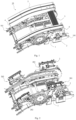
- a pre-assembled escalator module 10 includes a module side plate 1, a truss interface 101, a multifunctional connecting bracket 2, a comb plate 3, a skirt plate 4, a cover plate 5 and an entrance panel 6.
- the comb plate 3, skirt plate 4, cover plate 5 and entrance panel 6 can be collectively referred to as functional components, which are used to realize some functions of the escalator or for decoration.
- the multifunctional connecting bracket 2 is connected to the module side plate 1, and functional components are connected to the module side plate 1 through the multifunctional connecting bracket 2. This is different from the traditional multifunctional connecting bracket, which needs to be connected to the truss.
- the truss is located at the site, so the multifunctional connecting bracket can only be installed at the site, and then the functional components can be connected to the multifunctional connecting bracket.
- the multifunctional connecting bracket 2 is connected with the module side plate 1, and thus functional components can be connected with the module side plate 1 by connecting to the multifunctional connecting bracket 2, which allows for greatly improving the integration of the escalator module, realizing the pre-assembly of the escalator module in the factory, saving the time-consuming of on-site installation and debugging, reducing the installation error caused by on-site installation and improving the assembly accuracy.
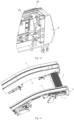
- fig. 1 also shows a truss interface 101 arranged at an end of the pre-assembled escalator module 10 for connecting the pre-assembled escalator module 10 to the truss.
- truss interfaces 101 can be provided at four locations along both ends in the horizontal direction and two sides in the lateral direction, which are used for hoisting the pre-assembled escalator module 10 to the truss on site and then installing and connecting it to the truss.
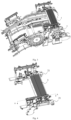
- Fig. 2 shows a perspective view of a pre-assembled escalator module 10 with functional components omitted, which shows a module side plate 1 and a multifunctional connecting bracket 2.
- the multifunctional connecting bracket 2 may include a first bracket 201 along the horizontal direction and a second bracket 202 inclined relative to the horizontal direction, and the skirt plate 4 and/or the cover plate 5 are both connected to the first bracket 201 and the second bracket 202.
- the comb plate 3 and the entrance panel 6 may be connected to the first bracket 201.
- For the upper escalator module it is necessary to connect the guide wheel assembly of the handrail belt and guide the handrail belt horizontally and obliquely, so it is necessary to provide two brackets.
- For the lower escalator module only one bracket is needed.
- figs. 3 to 7 show the connection of the comb plate 3 to the pre-assembled escalator module 10 according to at least one embodiment of the present disclosure.
- the multifunctional connecting bracket 2 may include a support plate 21, on which a plurality of mounting interfaces for mounting functional components, such as a plurality of C-shaped plates 23, a second profile piece 24 and a connecting bracket 25 connected with the support plate 21, are provided.
- the multifunctional connecting bracket 2 may further include a threaded plate 22 for mounting the comb plate 3.
- figs. 5 to 7 specifically show the connection between the comb plate 3 and the support plate 21.
- the comb plate 3 is connected to the support plate 21 through the adjusting screw assembly 7, and the threaded plate 22 is connected with the adjusting screw, and the support plate 21 is arranged between the comb plate 3 and the threaded plate 22.
- the adjusting screw assembly 7 may specifically include a long screw 71 and an adjusting screw 72, wherein the adjusting screw 72 has a through hole and an external thread, and the adjusting screw 72 is connected to the comb plate 3 through the external thread, and the long screw 71 is threaded with the threaded plate 22 through the through hole.
- a gasket 8 may also be provided between the support plate 21 and the threaded plate 22.
- the adjustment of the installation height of the comb plate 3 is important, which is related to the tightness between the steps and the comb plate 3. Therefore, it is necessary to provide components that can adjust the installation height of the comb plate 3.
- the length of the adjusting screw 72 can be customized, for example, there can be a plurality of adjusting screws 72 with different lengths.
- One end of the adjusting screw 72 supports the nut of the long screw 71, and the other end directly abuts against the gasket 8.
- the installation height of the comb plate 3 can be adjusted by adjusting screws 72 and gaskets 8 with different lengths. It is only necessary to replace the adjusting screws 72 with different lengths or the thickness and quantity of gaskets 8, without replacing the new comb plate 3 or the support plate 21. Thus the installation and debugging process is simple.
- the end of the adjusting screw 72 may be directly abutted against the support plate 21 without providing the gasket 8.
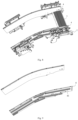
- figs. 8 to 10 show the connection of the skirt plate 4 to the pre-assembled escalator module 10 according to at least one embodiment of the present disclosure.
- the skirt plate 4 includes a first profile piece 41 arranged on the side, as shown in fig. 9 .
- the first profile piece 41 may be, for example, an aluminum profile, which includes a groove.
- a plurality of C-shaped plates 23 of the multifunctional connecting bracket 2 are connected to the first profile piece 41 of the skirt plate 4, thereby connecting the skirt plate 4 to the module side plate 1.
- a plurality of C-shaped plates 23 have two mounting holes in the vertical direction, which respectively correspond to the grooves of two first profile pieces 41 which are parallel in the up-down direction, and the C-shaped plates 23 and the first profile pieces 41 can be fixedly connected by screws.
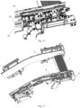
- figs. 13 and 14 show the connection of the cover plate 5 to the pre-assembled escalator module 10 according to at least one embodiment of the present disclosure.
- the cover plate 5 may include an inner cover plate and an outer cover plate.
- the cover plate 5 is connected to the second profile piece 24 through the connector 9, thereby connecting the cover plate 5 to the module side plate 1.
- the second profile piece 24 may be, for example, an aluminum profile, which includes a groove.
- the connector 9 is, for example, an angle iron, and both surfaces of the connector 9 are fixedly connected to the second profile piece 24 and the cover plate 5 by bolts respectively.
- both the first bracket 201 and the second bracket 202 may include a second profile piece 24, and both of them are connected with the skirt plate 4 and the cover plate 5.
- figs. 11 and 12 show the connection of the entrance panel 6 to the pre-assembled escalator module 10 according to at least one embodiment of the present disclosure.
- the entrance panel 6, also called the handrail belt entrance panel, has an opening to allow the handrail belt to pass through.
- the entrance panel 6 is connected to the connecting bracket 25, thereby connecting the entrance panel 6 to the module side panel 1.
- the entrance panels 6 can be two halves, which are respectively installed on both sides of the handrail belt and enclose to form an opening.
- the connecting bracket 25 can be, for example, an angle iron, one surface of which is connected to the second profile piece 24 and the other surface is connected to the entrance panel 6, thereby fixedly connecting the entrance panel 6 and the second profile piece 24.
- the present disclosure also proposes an escalator, which comprises a truss and the pre-assembled escalator module 10 as mentioned above, and the pre-assembled escalator module 10 is connected to the truss, for example, the truss interface 101 of the pre-assembled escalator module 10 is connected to the truss.
- the escalator can be, for example, an escalator modernized from an old escalator.
Landscapes
- Escalators And Moving Walkways (AREA)
Applications Claiming Priority (1)
| Application Number | Priority Date | Filing Date | Title |
|---|---|---|---|
| CN202310897714.6A CN119330197A (zh) | 2023-07-21 | 2023-07-21 | 预组装扶梯模组及自动扶梯 |
Publications (2)
| Publication Number | Publication Date |
|---|---|
| EP4495045A1 true EP4495045A1 (de) | 2025-01-22 |
| EP4495045B1 EP4495045B1 (de) | 2025-10-15 |
Family
ID=91961930
Family Applications (1)
| Application Number | Title | Priority Date | Filing Date |
|---|---|---|---|
| EP24189740.4A Active EP4495045B1 (de) | 2023-07-21 | 2024-07-19 | Vormontiertes fahrtreppenmodul aufweisend einer multifunktionale verbindungshalterung und fahrtreppe |
Country Status (3)
| Country | Link |
|---|---|
| EP (1) | EP4495045B1 (de) |
| CN (1) | CN119330197A (de) |
| ES (1) | ES3053492T3 (de) |
Families Citing this family (1)
| Publication number | Priority date | Publication date | Assignee | Title |
|---|---|---|---|---|
| CN116853922B (zh) * | 2023-07-21 | 2026-04-03 | 通力电梯有限公司 | 扶梯模组及自动扶梯 |
Citations (3)
| Publication number | Priority date | Publication date | Assignee | Title |
|---|---|---|---|---|
| EP1558515A1 (de) * | 2002-10-15 | 2005-08-03 | Kone Corporation | Methode zur modernisierung einer fahrtreppe |
| US20060096834A1 (en) * | 2004-11-08 | 2006-05-11 | Thomas Illedits | Escalator or moving walk |
| EP2757064A2 (de) * | 2013-01-18 | 2014-07-23 | Kone Corporation | Kammplatten-Kammplattenträgeranordnung und Kombinationskonstruktion mit Hubwerkzeug und Anordnung |
-
2023
- 2023-07-21 CN CN202310897714.6A patent/CN119330197A/zh active Pending
-
2024
- 2024-07-19 ES ES24189740T patent/ES3053492T3/es active Active
- 2024-07-19 EP EP24189740.4A patent/EP4495045B1/de active Active
Patent Citations (3)
| Publication number | Priority date | Publication date | Assignee | Title |
|---|---|---|---|---|
| EP1558515A1 (de) * | 2002-10-15 | 2005-08-03 | Kone Corporation | Methode zur modernisierung einer fahrtreppe |
| US20060096834A1 (en) * | 2004-11-08 | 2006-05-11 | Thomas Illedits | Escalator or moving walk |
| EP2757064A2 (de) * | 2013-01-18 | 2014-07-23 | Kone Corporation | Kammplatten-Kammplattenträgeranordnung und Kombinationskonstruktion mit Hubwerkzeug und Anordnung |
Also Published As
| Publication number | Publication date |
|---|---|
| CN119330197A (zh) | 2025-01-21 |
| EP4495045B1 (de) | 2025-10-15 |
| ES3053492T3 (en) | 2026-01-22 |
Similar Documents
| Publication | Publication Date | Title |
|---|---|---|
| EP4495045A1 (de) | Vormontiertes fahrtreppenmodul aufweisend einer multifunktionale verbindungshalterung und fahrtreppe | |
| CN207483122U (zh) | 一种装配式结构电梯井道及电梯 | |
| US20210053797A1 (en) | Guide rail bracket assembly | |
| EP2162377B1 (de) | Aufzugsschacht | |
| CN220998867U (zh) | 预组装扶梯模组及自动扶梯 | |
| US9561936B2 (en) | Elevator system door frame that supports guide rails | |
| CN220766235U (zh) | 扶梯模组及自动扶梯 | |
| EP4495046B1 (de) | Fahrtreppenmodul und fahrtreppe | |
| CN111634791B (zh) | 电梯层门组件安装方法 | |
| CN113772522A (zh) | 一种嵌入式合成型自动扶梯 | |
| CN110770158B (zh) | 乘客输送机的改造方法 | |
| CN213773992U (zh) | 一种高度可调的装配式底框结构 | |
| WO2020060083A1 (ko) | 조립식 몰딩 및 이를 이용한 외벽 알루미늄패널 시공방법 | |
| CN220886624U (zh) | 一种平台梯井道框架结构 | |
| CN220537265U (zh) | 一种带轿厢的一体化加装电梯钢结构井道 | |
| CN209322285U (zh) | 一种扶梯板件的集成模块 | |
| CN220131671U (zh) | 一种嵌入式自动扶梯 | |
| JP7118252B2 (ja) | 乗客コンベヤのトラス | |
| CN220504355U (zh) | 一种分体式固定玻璃槽 | |
| CN218403228U (zh) | 一种家用电梯的框架井道 | |
| KR20240165258A (ko) | 임베디드형 에스컬레이터 및 조립 방법 | |
| CN222295523U (zh) | 一种相互加强壁板结构 | |
| US20260021996A1 (en) | Handrail tensioning device and escalator installation module comprising the same | |
| CN220646404U (zh) | 一种led显示屏超薄拼装结构支架 | |
| JPH0812236A (ja) | エレベータ乗場敷居 |
Legal Events
| Date | Code | Title | Description |
|---|---|---|---|
| PUAI | Public reference made under article 153(3) epc to a published international application that has entered the european phase |
Free format text: ORIGINAL CODE: 0009012 |
|
| STAA | Information on the status of an ep patent application or granted ep patent |
Free format text: STATUS: THE APPLICATION HAS BEEN PUBLISHED |
|
| AK | Designated contracting states |
Kind code of ref document: A1 Designated state(s): AL AT BE BG CH CY CZ DE DK EE ES FI FR GB GR HR HU IE IS IT LI LT LU LV MC ME MK MT NL NO PL PT RO RS SE SI SK SM TR |
|
| P01 | Opt-out of the competence of the unified patent court (upc) registered |
Free format text: CASE NUMBER: APP_17303/2025 Effective date: 20250409 |
|
| STAA | Information on the status of an ep patent application or granted ep patent |
Free format text: STATUS: REQUEST FOR EXAMINATION WAS MADE |
|
| GRAP | Despatch of communication of intention to grant a patent |
Free format text: ORIGINAL CODE: EPIDOSNIGR1 |
|
| STAA | Information on the status of an ep patent application or granted ep patent |
Free format text: STATUS: GRANT OF PATENT IS INTENDED |
|
| 17P | Request for examination filed |
Effective date: 20250521 |
|
| INTG | Intention to grant announced |
Effective date: 20250625 |
|
| GRAS | Grant fee paid |
Free format text: ORIGINAL CODE: EPIDOSNIGR3 |
|
| GRAA | (expected) grant |
Free format text: ORIGINAL CODE: 0009210 |
|
| STAA | Information on the status of an ep patent application or granted ep patent |
Free format text: STATUS: THE PATENT HAS BEEN GRANTED |
|
| AK | Designated contracting states |
Kind code of ref document: B1 Designated state(s): AL AT BE BG CH CY CZ DE DK EE ES FI FR GB GR HR HU IE IS IT LI LT LU LV MC ME MK MT NL NO PL PT RO RS SE SI SK SM TR |
|
| REG | Reference to a national code |
Ref country code: GB Ref legal event code: FG4D Ref country code: CH Ref legal event code: F10 Free format text: ST27 STATUS EVENT CODE: U-0-0-F10-F00 (AS PROVIDED BY THE NATIONAL OFFICE) Effective date: 20251015 |
|
| REG | Reference to a national code |
Ref country code: DE Ref legal event code: R096 Ref document number: 602024000943 Country of ref document: DE |
|
| REG | Reference to a national code |
Ref country code: IE Ref legal event code: FG4D |
|
| REG | Reference to a national code |
Ref country code: ES Ref legal event code: FG2A Ref document number: 3053492 Country of ref document: ES Kind code of ref document: T3 Effective date: 20260122 |
|
| REG | Reference to a national code |
Ref country code: NL Ref legal event code: MP Effective date: 20251015 |
|
| REG | Reference to a national code |
Ref country code: AT Ref legal event code: MK05 Ref document number: 1846821 Country of ref document: AT Kind code of ref document: T Effective date: 20251015 |
|
| PG25 | Lapsed in a contracting state [announced via postgrant information from national office to epo] |
Ref country code: NL Free format text: LAPSE BECAUSE OF FAILURE TO SUBMIT A TRANSLATION OF THE DESCRIPTION OR TO PAY THE FEE WITHIN THE PRESCRIBED TIME-LIMIT Effective date: 20251015 |
|
| REG | Reference to a national code |
Ref country code: LT Ref legal event code: MG9D |
|
| PG25 | Lapsed in a contracting state [announced via postgrant information from national office to epo] |
Ref country code: NO Free format text: LAPSE BECAUSE OF FAILURE TO SUBMIT A TRANSLATION OF THE DESCRIPTION OR TO PAY THE FEE WITHIN THE PRESCRIBED TIME-LIMIT Effective date: 20260115 |
|
| PG25 | Lapsed in a contracting state [announced via postgrant information from national office to epo] |
Ref country code: AT Free format text: LAPSE BECAUSE OF FAILURE TO SUBMIT A TRANSLATION OF THE DESCRIPTION OR TO PAY THE FEE WITHIN THE PRESCRIBED TIME-LIMIT Effective date: 20251015 Ref country code: HR Free format text: LAPSE BECAUSE OF FAILURE TO SUBMIT A TRANSLATION OF THE DESCRIPTION OR TO PAY THE FEE WITHIN THE PRESCRIBED TIME-LIMIT Effective date: 20251015 Ref country code: FI Free format text: LAPSE BECAUSE OF FAILURE TO SUBMIT A TRANSLATION OF THE DESCRIPTION OR TO PAY THE FEE WITHIN THE PRESCRIBED TIME-LIMIT Effective date: 20251015 |
|
| PG25 | Lapsed in a contracting state [announced via postgrant information from national office to epo] |
Ref country code: RS Free format text: LAPSE BECAUSE OF FAILURE TO SUBMIT A TRANSLATION OF THE DESCRIPTION OR TO PAY THE FEE WITHIN THE PRESCRIBED TIME-LIMIT Effective date: 20260115 |
|
| PG25 | Lapsed in a contracting state [announced via postgrant information from national office to epo] |
Ref country code: IS Free format text: LAPSE BECAUSE OF FAILURE TO SUBMIT A TRANSLATION OF THE DESCRIPTION OR TO PAY THE FEE WITHIN THE PRESCRIBED TIME-LIMIT Effective date: 20260215 |