EP4495044A1 - Teleskopischer linearoperator für eine aufzugsschiebetür - Google Patents
Teleskopischer linearoperator für eine aufzugsschiebetür Download PDFInfo
- Publication number
- EP4495044A1 EP4495044A1 EP24188025.1A EP24188025A EP4495044A1 EP 4495044 A1 EP4495044 A1 EP 4495044A1 EP 24188025 A EP24188025 A EP 24188025A EP 4495044 A1 EP4495044 A1 EP 4495044A1
- Authority
- EP
- European Patent Office
- Prior art keywords
- door
- conveyor
- linear operator
- wheel
- arm
- Prior art date
- Legal status (The legal status is an assumption and is not a legal conclusion. Google has not performed a legal analysis and makes no representation as to the accuracy of the status listed.)
- Pending
Links
Images

Classifications
-
- B—PERFORMING OPERATIONS; TRANSPORTING
- B66—HOISTING; LIFTING; HAULING
- B66B—ELEVATORS; ESCALATORS OR MOVING WALKWAYS
- B66B13/00—Doors, gates, or other apparatus controlling access to, or exit from, cages or lift well landings
- B66B13/02—Door or gate operation
- B66B13/06—Door or gate operation of sliding doors
- B66B13/08—Door or gate operation of sliding doors guided for horizontal movement
-
- B—PERFORMING OPERATIONS; TRANSPORTING
- B66—HOISTING; LIFTING; HAULING
- B66B—ELEVATORS; ESCALATORS OR MOVING WALKWAYS
- B66B13/00—Doors, gates, or other apparatus controlling access to, or exit from, cages or lift well landings
- B66B13/02—Door or gate operation
- B66B13/14—Control systems or devices
-
- B—PERFORMING OPERATIONS; TRANSPORTING
- B66—HOISTING; LIFTING; HAULING
- B66B—ELEVATORS; ESCALATORS OR MOVING WALKWAYS
- B66B13/00—Doors, gates, or other apparatus controlling access to, or exit from, cages or lift well landings
- B66B13/02—Door or gate operation
- B66B13/06—Door or gate operation of sliding doors
-
- E—FIXED CONSTRUCTIONS
- E05—LOCKS; KEYS; WINDOW OR DOOR FITTINGS; SAFES
- E05F—DEVICES FOR MOVING WINGS INTO OPEN OR CLOSED POSITION; CHECKS FOR WINGS; WING FITTINGS NOT OTHERWISE PROVIDED FOR, CONCERNED WITH THE FUNCTIONING OF THE WING
- E05F15/00—Power-operated mechanisms for wings
- E05F15/60—Power-operated mechanisms for wings using electrical actuators
- E05F15/603—Power-operated mechanisms for wings using electrical actuators using rotary electromotors
- E05F15/632—Power-operated mechanisms for wings using electrical actuators using rotary electromotors for horizontally-sliding wings
- E05F15/643—Power-operated mechanisms for wings using electrical actuators using rotary electromotors for horizontally-sliding wings operated by flexible elongated pulling elements, e.g. belts, chains or cables
Definitions
- the present disclosure relates to powered door operators for sliding doors, and more particularly to powered door operators for elevator cars.
- Sliding doors may be opened by powered door operators rather than opened manually.
- powered door operators are used to open the doors of an elevator car.
- elevator door operators include harmonic-type elevator door operators and linear-type door operators, each type of operator having relative advantages and drawbacks. For example, in many applications harmonic operators last longer than linear operators but are harder to install.
- a first step to installing the operator is to select an operator of appropriate size. That is, to select an operator sized to ensure that the movement of the door by the operator is the movement required to correctly open and close the door. For example, for a side sliding elevator door a linear operator is selected so that the size of the operator along the direction door movement is sufficient to allow the door to fully open when people want to enter or exit the elevator car and to fully close before the elevator car moves between floors.
- the installation or replacement of a linear operator carries the burden of acquiring a linear operator of correct size.
- a telescopic linear operator may be used in situations requiring varying amounts of door movement, thereby allowing a single telescopic linear operator to serve as substitute for a multiple of non-telescopic linear operators.
- an elevator installation and service company may stock one type of telescopic linear operator that can be used for a range of jobs instead of stocking many non-telescopic linear operators in hopes that one of the non-telescopic operators is correctly sized for a given job.
- the presently disclosed technology includes a telescopic linear operator that may be selectively sized for use in a range of applications.
- a linear operator for a sliding door includes a body; a first wheel rotatably attached to the body at a first position on the body; an arm movably attached to the body, translatable in a direction parallel or substantially parallel to a longitudinal axis of the body, and fixable to the body at a desired translation position; a second wheel rotatably attached to the arm at a second position on the arm; and a conveyor extending between the first wheel and the second wheel, movable about the first wheel and the second wheel, and operable for attachment to a door, wherein when the arm is at a desired translation position, a distance between the first position and the second position corresponds to a desired movement distance of the door when the door is attached to the conveyor.
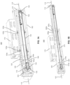
- Fig 1A is a perspective view of a telescopic linear operator 100 in a fully retracted position.
- the linear operator 100 includes a body 105 and an arm 110.
- the arm 110 is movably attached to the body 105 such that the arm 110 can translate, or "telescope," in a direction parallel or substantially parallel to a longitudinal axis 115 of the body.
- the arm 110 is translated toward the body 105 to a maximum extent, thereby placing the arm in a fully retracted position which, in the example of Fig. 1A , places the arm 110 within the bounds of the body 105.
- Fig. 1A As can be further seen from Fig.
- the arm 110 includes a multiple of arm through-holes 120, e.g., arm through-holes 120a and 120b.
- the body 105 includes a multiple of body through-holes which may be selectively aligned with the arm through-holes 120, although the body through-holes are not visible in Fig. 1A .
- the arm 110 may be fixed to the body 105 when the arm 110 is in a desired translation position, e.g., the fully retracted position of Fig. 1A , by aligning one or more of the arm through-holes 120 with one or more of the body through-holes and inserting one or more fasteners, e.g., bolts 125a and 125b, into the aligned through-holes.
- the arm through-holes 120 may have an oval shape to allow for an increased range of positions at which the arm 110 is fixable to the body 105.
- the linear operator 100 of Fig. 1A further includes a first wheel 130 rotatably attached to the body 105 at a first position 135 on the body 105, a second wheel 140 rotatably attached to the arm 110 at a second position 145 on the arm 110, and a conveyor 150 extending between the first wheel 130 and the second wheel 140.
- the conveyor 150 is movable about the first wheel 130 and the second wheel 140.
- the conveyor 150 has a first end 155a and a second end 155b, which are configured for attachment to a conveyor clamp (not shown), the conveyor clamp filling a space 160 between the first end 155a and the second end 155b such that the conveyor 150 and conveyor clamp form a closed loop about the first wheel 130 and the second wheel 140.
- the conveyor clamp is configured for attachment to a door bracket (not shown) which is, in turn, configured for attachment to a door (not shown).
- a door bracket (not shown) which is, in turn, configured for attachment to a door (not shown).
- the conveyor 150 may not have a first end 155a or a second end 155b, and may itself form a closed loop.
- a conveyor clamp may be attached to the closed loop conveyor, thereby providing an attachment point at which a door may be attached to the conveyor 150 through a door bracket so that the conveyor 150 may move the door.
- the conveyor 150 may take many alternative forms. For instance, the conveyor 150 may take the form of a belt, a cable, or a chain.
- first wheel 130 and the second wheel 140 may be a sprocket-type wheel.
- the conveyor 150 may include grooves or holes for engaging sprocket teeth on the first wheel 130 and/or second wheel 140. In this manner, the conveyor 150 may rotate with the first wheel 130 and/or second wheel 140 without slippage.
- the linear operator 100 may include a motor 165.
- the motor 165 may drive a shaft 170 that is located at the first position 135 and operates to rotate the first wheel 130, thereby moving the conveyor 150.
- the motor 165 may supply the force to move a door coupled to the conveyor 150.
- the shaft 170 is a central axel of the motor 165, however it should be noted that other arrangements are possible.
- the motor 165 may be offset from the shaft 170 and connected to the shaft 170 through one or more gears.
- the embodiments are not limited to use of one motor.
- some embodiments may include two motors, one motor attached to the body 105 and operable to drive the first wheel 130 and a second motor attached to the arm 110 and operable to drive the second wheel 140.
- the linear operator 100 may further include a drive unit 175 for controlling the one or more motors.
- the drive unit 175 may control motor 165.
- the drive unit 175 may include a power supply, electrically connected to the motor 165, and a processor for selectively switching power from the power supply to the motor 165 as needed by the motor 165 to open and close a door operated by operator 100.
- the linear operator 100 may include a base 180.
- the base 180 may be integral with, or attached to, the body 105.
- the base 180 is provided to facilitate secure attachment of the linear operator 100 proximate one or more doors to be controlled by the operator 100.
- the base 180 may be secured to an elevator car door header when the operator is installed to control a door of the elevator car.
- FIG. 1B the figure shows a perspective view of the telescopic linear operator 100 of Fig. 1A in a fully extended position.
- Fig. 1B does not show fixation of the linear operator 100 in the fully extended position; however, as can be seen from Fig. 1B , one or more of arm through-holes 205a, 205b, and 205c could be used to fix arm 110 to body 105 in the fully extended position.
- each of arm through-holes 205a, 205b, and 205c aligns with a corresponding body through-hole
- the arm 110 may be fixed to the body 105 by inserting one or more fasteners in one or more of the aligned through-holes, e.g., by placing a bolt in one of the aligned through-holes and securing the bolt with a nut.
- a longer conveyor is required to accommodate the increased distance between the first position 135 and the second position 140, and thus in the Fig. 1B configuration the linear operator 100 employes a conveyor 210 which is longer than conveyor 150. Nevertheless, the conveyor 210 may have the same or similar structure as that of conveyor 150.
- the conveyor 210 extends between the first wheel 130 and the second wheel 140, is movable about the first wheel 130 and the second wheel 140, and has a first end 215a and a second end 215b.
- the first end 215a and the second end 215b may be configured for attachment to a conveyor clamp (not shown), the conveyor clamp filling a space 220 between the first end 215a and the second end 215b such that the conveyor 210 and conveyor clamp form a closed loop about the first wheel 130 and the second wheel 140.
- the conveyor clamp is configured for attachment to a door bracket (not shown) which is, in turn, configured for attachment to a door (not shown).
- FIG. 2 the figure is a perspective view of the telescopic linear operator 100 of Figs. 1A and 1B as used in a side sliding elevator car door arrangement 300 of an elevator car.
- the view of Fig. 2 is from outside the elevator car, looking at the front of the elevator car from inside the elevator hoistway.
- the linear operator 100 is secured in a desired translation position that is between the fully retracted position of Fig. 1A and the fully extended position of Fig. 1B .
- Fig. 2 the linear operator 100 is secured in a desired translation position that is between the fully retracted position of Fig. 1A and the fully extended position of Fig. 1B .
- the linear operator 100 is configured to move a side sliding door 310 in a closing direction, represented by arrow 315, and in an opening direction, represented by arrow 320, both the closing direction 315 and the opening direction 320 being parallel or substantially parallel to the longitudinal axis 115 of the linear operator 100.
- the operator 100 may move the door 310 between a fully closed position and a fully opened position. In Fig. 2 , the door 310 is shown in the fully opened position.
- the door 310 is attached to two rollers 325a and 325b.
- the rollers 325a and 325b are, in turn, positioned within a track 330, and the track 330 is secured to a header 335 of the elevator car, with the header 335 being attached to a car wall 340 of the elevator car.
- the rollers 325a and 325b allow the door 310 to move along the direction of the track 330 between the fully closed position and the fully opened position. As can be seen from Fig. 2 , when in the fully opened position the door 310 is positioned behind the car wall 340 - from the perspective of a viewer inside the car.
- the linear operator 100 may be oriented parallel to, or substantially parallel to, the track 330 and secured to the header 335.
- the base 180 of the linear operator 100 is secured to the top of the header 335, although other configurations are possible.
- the door 310 is attached to the linear operator 100 through a door bracket 345 and a conveyor clamp 350, with the conveyor clamp 350 being part of, or attached to, a conveyor 355 of the linear operator 100.
- motor 165 rotates the first wheel 130
- the first wheel 130 moves the conveyor 355 which, in turn moves the conveyor clamp 350, door bracket 345, and door 310.
- Rotation of the first wheel 130 in the counterclockwise direction moves the door 310 in the closing direction 315
- rotation of the first wheel 130 in the clockwise direction moves the door 310 in the opening direction 320.
- a gate switch 360 for providing an indication that the door 310 is in the fully closed position.
- the gate switch 360 may be provided as part of the linear operator 100 or as an attachment to the linear operator 100.
- the gate switch 360 may be electrically coupled to the drive unit 175 and activated by a roller (not shown) attached to the conveyor clamp 350. When the roller activates the gate switch 360, the gate switch sends a signal to the drive unit 175 indicating that the door 310 is in the fully closed position. Thereby, providing a failsafe that prevents the elevator car from moving without the door 310 being fully closed.
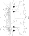
- FIG. 3 the figure is a profile view of the telescopic linear operator 100 of Figs. 1A, 1B , and 2 as used in a center parting elevator car door arrangement 400.
- the view of Fig. 3 is from outside the elevator car, looking at the front of the elevator car from inside the elevator hoistway.
- the linear operator 100 is secured in a desired translation position that is between the fully retracted position of Fig. 1A and the fully extended position of Fig. 1B .
- the linear operator 100 is configured to move a first elevator car door 405a and a second elevator car door 450b in respective closing directions and respective opening directions.
- the closing direction is represented by arrow 410a and the opening direction is represented by arrow 410b.
- the closing direction is represented by arrow 415a and the opening direction is represented by arrow 415b.
- Each of the closing directions 410a and 415a and the opening directions 410b and 415b are parallel or substantially parallel to the longitudinal axis 115 of the linear operator 100.
- the operator 100 may move the doors 405a and 405b between a fully closed position, represented by dashed line 420, and a fully opened position. In Fig. 3 , the doors 405a and 405b are shown in the fully opened position.
- the doors 405a and 405b are attached to respective pairs of rollers 425 and 430.
- the pairs of rollers 425 and 430 are, in turn, positioned within a track 435, and the track 435 is secured to a header 440 of the elevator car, with the header 440 being attached to a car wall (not shown) of the elevator car.
- the pairs of rollers 425 and 430 respectively allow the doors 405a and 405b to move along the direction of the track 435 between the fully closed positions of the doors 405a and 405b and the fully opened positions of the doors 405a and 405b.
- the doors 405a and 405b are positioned behind the car wall - from the perspective of a viewer inside the car.
- the linear operator 100 may be oriented parallel to, or substantially parallel to, the track 435 and secured to the header 440.
- the base 180 of the linear operator 100 is secured to the top of the header 440, although other configurations are possible.
- first door 405a is attached to the linear operator 100 through a first door bracket 445a and a first conveyor clamp 450a, with the first conveyor clamp 450a being part of, or attached to, a conveyor 455 of the linear operator 100; and the second door 405b is attached to the linear operator 100 through a second door bracket 445b and a second conveyor clamp 450b, with the second conveyor clamp 450b being part of, or attached to, the conveyor 455 of the linear operator 100.
- first conveyor clamp 450a is attached to the conveyor 455 at a lower conveyor position 455a
- the second conveyor clamp 450b is attached to the conveyor 455 at an upper conveyor position 455b.
- the first wheel 130 moves the conveyor 455 such that the conveyor clamp 450a, door bracket 445a, and door 405a move in the opening direction 410b of door 405a; and such that the conveyor clamp 450b, door bracket 445b, and door 405b move in the opening direction 415b of door 405b.
- the conveyor 455 is formed of a first portion 460 and a second portion 465.
- the first portion 460 has a first end 460a and a second end 460b
- the second portion 465 has a first end 465a and a second end 465b.
- the first conveyor clamp 450a couples the first end 460a of the first portion 460 to the first end 465a of the second portion 465.
- the second conveyor clamp 450b couples second end 460b of the first portion 460 to the second end 465b of the second portion 465.
- conveyor 455 as depicted in Fig. 3 is merely illustrative.
- the conveyor 455 need not be formed of two portions.
- the conveyor 455 may itself form a closed loop, without the first conveyor clamp 450a and the second conveyor clamp 450b.
- first and second conveyor clamps may be attached to the closed loop conveyor 455, with the first conveyor clamp being attached to the conveyor 455 at the lower conveyor position 455a and the second conveyor clamp being attached to the conveyor 455 at the upper conveyor position 455b.
- the conveyor 455 may take many alternative forms, such as the form of a belt, a cable, or a chain.
- Embodiments of the present technology include, but are not restricted to, the following.
Landscapes
- Engineering & Computer Science (AREA)
- Automation & Control Theory (AREA)
- Power-Operated Mechanisms For Wings (AREA)
- Transmission Devices (AREA)
Applications Claiming Priority (1)
| Application Number | Priority Date | Filing Date | Title |
|---|---|---|---|
| US18/223,247 US12227389B2 (en) | 2023-07-18 | 2023-07-18 | Telescopic linear operator |
Publications (1)
| Publication Number | Publication Date |
|---|---|
| EP4495044A1 true EP4495044A1 (de) | 2025-01-22 |
Family
ID=91924331
Family Applications (1)
| Application Number | Title | Priority Date | Filing Date |
|---|---|---|---|
| EP24188025.1A Pending EP4495044A1 (de) | 2023-07-18 | 2024-07-11 | Teleskopischer linearoperator für eine aufzugsschiebetür |
Country Status (5)
| Country | Link |
|---|---|
| US (1) | US12227389B2 (de) |
| EP (1) | EP4495044A1 (de) |
| CN (1) | CN119330194A (de) |
| CA (1) | CA3247753A1 (de) |
| MX (1) | MX2024008675A (de) |
Citations (4)
| Publication number | Priority date | Publication date | Assignee | Title |
|---|---|---|---|---|
| EP0841285A1 (de) * | 1996-11-07 | 1998-05-13 | Otis Elevator Company | Aufzugskabinentürsystem |
| US5797471A (en) * | 1996-07-19 | 1998-08-25 | Montgomery Kone Inc. | Linear door drive operator |
| US5878846A (en) * | 1996-10-07 | 1999-03-09 | Vertisys, Inc. | Light duty elevator door operator |
| EP2743226A1 (de) * | 2012-12-17 | 2014-06-18 | Inventio AG | Türe für eine Aufzugsanlage |
Family Cites Families (11)
| Publication number | Priority date | Publication date | Assignee | Title |
|---|---|---|---|---|
| DE19780143B4 (de) * | 1996-03-01 | 2011-09-01 | Geze Gmbh | Schiebetüranlage |
| ATE193580T1 (de) * | 1996-08-13 | 2000-06-15 | Inventio Ag | Träger für türantriebe von aufzügen |
| US5711112A (en) * | 1996-09-03 | 1998-01-27 | Otis Elevator Company | Double-drive automatic sliding door operator |
| US7331141B2 (en) * | 2004-06-14 | 2008-02-19 | Door Control Services, Inc. | Automatic door control apparatus |
| US20080190708A1 (en) * | 2007-02-09 | 2008-08-14 | Atlantic Tech System, Llc | Elevator door operator |
| ES2377631B1 (es) * | 2009-04-16 | 2013-02-05 | Klein Ibérica, S.A. | Dispositivo de desplazamiento simultáneo para puertas correderas. |
| DE112018007649T5 (de) * | 2018-05-22 | 2021-03-18 | Mitsubishi Electric Corporation | Aufzugskabinentürvorrichtung |
| CA3104046C (en) * | 2018-08-09 | 2023-09-26 | Nabtesco Corporation | System and method for automatic door maintenance management |
| US11691852B2 (en) * | 2020-12-04 | 2023-07-04 | Fujitec Co., Ltd. | Height raising member for raising mounting position of motor for elevator door, car door device equipped with height raising member for raising mounting position of motor for elevator door, and elevator car equipped with height raising member for raising mounting position of motor for elevator door |
| EP4323614A4 (de) * | 2021-04-16 | 2025-02-26 | Kineco Limited | Exzenteranordnung für eine schiebetür |
| US12577823B2 (en) * | 2021-09-27 | 2026-03-17 | Allegion Access Technologies LLC | Multi-panel door system, and dual-synchronization drive assembly for a multi-panel door system |
-
2023
- 2023-07-18 US US18/223,247 patent/US12227389B2/en active Active
-
2024
- 2024-07-09 CA CA3247753A patent/CA3247753A1/en active Pending
- 2024-07-11 MX MX2024008675A patent/MX2024008675A/es unknown
- 2024-07-11 EP EP24188025.1A patent/EP4495044A1/de active Pending
- 2024-07-18 CN CN202410964613.0A patent/CN119330194A/zh active Pending
Patent Citations (4)
| Publication number | Priority date | Publication date | Assignee | Title |
|---|---|---|---|---|
| US5797471A (en) * | 1996-07-19 | 1998-08-25 | Montgomery Kone Inc. | Linear door drive operator |
| US5878846A (en) * | 1996-10-07 | 1999-03-09 | Vertisys, Inc. | Light duty elevator door operator |
| EP0841285A1 (de) * | 1996-11-07 | 1998-05-13 | Otis Elevator Company | Aufzugskabinentürsystem |
| EP2743226A1 (de) * | 2012-12-17 | 2014-06-18 | Inventio AG | Türe für eine Aufzugsanlage |
Also Published As
| Publication number | Publication date |
|---|---|
| US12227389B2 (en) | 2025-02-18 |
| CN119330194A (zh) | 2025-01-21 |
| CA3247753A1 (en) | 2025-06-06 |
| US20250026613A1 (en) | 2025-01-23 |
| MX2024008675A (es) | 2025-02-10 |
Similar Documents
| Publication | Publication Date | Title |
|---|---|---|
| EP1942073B1 (de) | Aufzugtürensystem | |
| JP7821730B2 (ja) | ドアオペレータシステム | |
| EP2143682A1 (de) | Türöffnungsvorrichtung für aufzug | |
| JP7702415B2 (ja) | ドアオペレータシステム | |
| US5701973A (en) | Linear belt door operator | |
| US11691852B2 (en) | Height raising member for raising mounting position of motor for elevator door, car door device equipped with height raising member for raising mounting position of motor for elevator door, and elevator car equipped with height raising member for raising mounting position of motor for elevator door | |
| JP2010208761A (ja) | エレベータのかごドア装置 | |
| US12227389B2 (en) | Telescopic linear operator | |
| US6719033B2 (en) | Power operated multi-paneled garage door opening system | |
| US11578525B2 (en) | Door operator with isolated components | |
| US5659160A (en) | Linear belt door operator | |
| JP2010173768A (ja) | エレベータドア用ドア装置 | |
| HK40115588A (zh) | 伸缩式线性操作器 | |
| EP2741992B1 (de) | Antrieb und aufzugselektronik in einer grundplatte | |
| US10718149B2 (en) | Sectional door driving device | |
| EP3029231A1 (de) | Türöffnungs-/-schliessvorrichtung und fahrzeugtürmodul | |
| CN112188989B (zh) | 电梯的轿厢门装置 | |
| JP3347855B2 (ja) | 手動開閉式シャッターの後付け駆動装置 | |
| JP2012062720A (ja) | 自動ドア用取付装置 | |
| EP1736630B1 (de) | Einziehbare Sicherheitsrandeinheit, Installationsmethode und resultierendes Türsystem | |
| JPH07203651A (ja) | 電動機取付機構 | |
| JP7495898B2 (ja) | 乗客コンベア及び乗客コンベアのレール調整機構 | |
| AU2018100103A4 (en) | Sectional door driving device | |
| JP6570696B2 (ja) | 自動ドア取付装置 | |
| AU2018200551B2 (en) | Sectional door driving device |
Legal Events
| Date | Code | Title | Description |
|---|---|---|---|
| PUAI | Public reference made under article 153(3) epc to a published international application that has entered the european phase |
Free format text: ORIGINAL CODE: 0009012 |
|
| STAA | Information on the status of an ep patent application or granted ep patent |
Free format text: STATUS: THE APPLICATION HAS BEEN PUBLISHED |
|
| AK | Designated contracting states |
Kind code of ref document: A1 Designated state(s): AL AT BE BG CH CY CZ DE DK EE ES FI FR GB GR HR HU IE IS IT LI LT LU LV MC ME MK MT NL NO PL PT RO RS SE SI SK SM TR |
|
| STAA | Information on the status of an ep patent application or granted ep patent |
Free format text: STATUS: REQUEST FOR EXAMINATION WAS MADE |
|
| 17P | Request for examination filed |
Effective date: 20250722 |
|
| GRAP | Despatch of communication of intention to grant a patent |
Free format text: ORIGINAL CODE: EPIDOSNIGR1 |
|
| STAA | Information on the status of an ep patent application or granted ep patent |
Free format text: STATUS: GRANT OF PATENT IS INTENDED |
|
| INTG | Intention to grant announced |
Effective date: 20260302 |