EP4494902A1 - Remorque de véhicule avec un capteur pour mesurer et/ou déterminer la charge par essieu agissant sur l'essieu de la remorque de véhicule par le chargement - Google Patents
Remorque de véhicule avec un capteur pour mesurer et/ou déterminer la charge par essieu agissant sur l'essieu de la remorque de véhicule par le chargement Download PDFInfo
- Publication number
- EP4494902A1 EP4494902A1 EP24189741.2A EP24189741A EP4494902A1 EP 4494902 A1 EP4494902 A1 EP 4494902A1 EP 24189741 A EP24189741 A EP 24189741A EP 4494902 A1 EP4494902 A1 EP 4494902A1
- Authority
- EP
- European Patent Office
- Prior art keywords
- sensor
- axle
- vehicle trailer
- load
- designed
- Prior art date
- Legal status (The legal status is an assumption and is not a legal conclusion. Google has not performed a legal analysis and makes no representation as to the accuracy of the status listed.)
- Withdrawn
Links
Images


Classifications
-
- B—PERFORMING OPERATIONS; TRANSPORTING
- B60—VEHICLES IN GENERAL
- B60G—VEHICLE SUSPENSION ARRANGEMENTS
- B60G17/00—Resilient suspensions having means for adjusting the spring or vibration-damper characteristics, for regulating the distance between a supporting surface and a sprung part of vehicle or for locking suspension during use to meet varying vehicular or surface conditions, e.g. due to speed or load
- B60G17/015—Resilient suspensions having means for adjusting the spring or vibration-damper characteristics, for regulating the distance between a supporting surface and a sprung part of vehicle or for locking suspension during use to meet varying vehicular or surface conditions, e.g. due to speed or load the regulating means comprising electric or electronic elements
- B60G17/019—Resilient suspensions having means for adjusting the spring or vibration-damper characteristics, for regulating the distance between a supporting surface and a sprung part of vehicle or for locking suspension during use to meet varying vehicular or surface conditions, e.g. due to speed or load the regulating means comprising electric or electronic elements characterised by the type of sensor or the arrangement thereof
-
- G—PHYSICS
- G01—MEASURING; TESTING
- G01G—WEIGHING
- G01G19/00—Weighing apparatus or methods adapted for special purposes not provided for in the preceding groups
- G01G19/08—Weighing apparatus or methods adapted for special purposes not provided for in the preceding groups for incorporation in vehicles
- G01G19/12—Weighing apparatus or methods adapted for special purposes not provided for in the preceding groups for incorporation in vehicles having electrical weight-sensitive devices
Definitions
- the present invention relates to a vehicle trailer with a sensor for measuring and/or determining the axle load acting on the axle of the vehicle trailer due to the load according to the preamble of patent claim 1.
- the present invention serves to determine the loading state of a car trailer with a suspended axle by measuring the compression and rebound travel in the parked or moving state and determining the resulting axle pivot point positions in order to determine critical measuring points and forward the values by radio transmission through a telematics module via the mobile network to a central telematics service.
- Overload detection is primarily used in the vehicle rental (trailer rental) of car trailers and in the series equipment of car trailers by manufacturers in the factory, but is not limited to car trailers, but can also be used for suspended trailers of any weight class or vehicle class.
- overloading trailers represents a significant road safety risk that has not yet been addressed by any trailer manufacturer.
- the present invention is based on the object of eliminating the aforementioned disadvantages and of creating a vehicle trailer which is designed to easily measure or determine a load of the vehicle trailer.
- the vehicle trailer according to the invention is equipped with a loading area for transporting goods, a drawbar for coupling to a towing vehicle, at least one axle with wheels and a sensor for measuring and/or determining the axle load acting on the axle of the vehicle trailer due to the load.
- the vehicle trailer further comprises at least one device for transmitting the signal determined by the sensor in order to transmit this signal to a digital evaluation unit which is designed to determine and/or evaluate an overload state of the vehicle trailer either by means of state detection or measured value analysis of the axle load and to forward the overload state to at least one receiving unit.
- the vehicle trailer is characterized in that the sensor is a motion and/or position sensor which is designed to detect a vertical movement, rotation and/or rotation of a) the axle, and/or b) the axle pivot point and/or c) a movable, rotating or rotating component connected to the axle or the axle body (axle bridge).
- the sensor is a motion and/or position sensor which is designed to detect a vertical movement, rotation and/or rotation of a) the axle, and/or b) the axle pivot point and/or c) a movable, rotating or rotating component connected to the axle or the axle body (axle bridge).
- the component may in particular be one or more steering knuckles, a wheel hub, a leaf spring or any other (preferably movable) part or component on the vehicle trailer that is directly or indirectly connected to the axle or axle body.
- the load can be determined continuously. It can be advantageous if, preferably when defined load limit values are exceeded, at least one signal and/or at least one piece of information is transmitted to a receiving unit of a receiver, here for example the trailer manufacturer, the rental company or the owner of a trailer.
- a telemetry unit connected to the mobile network which is, for example, permanently connected to the trailer, sends a signal to an IT service, which advantageously evaluates the signal and/or generates an alarm.
- an IT service which advantageously evaluates the signal and/or generates an alarm.
- Overload detection can be technically implemented by continuously measuring the loading status of a vehicle trailer and/or by determining the dynamic suspension travel while driving or the static suspension travel in the stationary and loaded or unloaded state by determining whether the suspension travel has been exceeded or whether a predefined measuring point of an axle position sensor or pressure sensor has been exceeded.
- the load can be measured on trailers with rubber-sprung axles, shock absorber-guided independent suspension or leaf springs with or without shock absorbers and in any other type of suspension in which the compression travel and initial and final positions are determined by means of an electronic, resistance-changing, switching or optical sensor or a contact switch.
- the invention also describes the determination of the individual axle loads via any sensor technology that allows sequential axle loads to be consolidated by position sensors and to be able to detect an overload by measuring and evaluating the axle loads (e.g. by means of averaged average values or by applying artificial intelligence or machine learning algorithms).
- the axle pivot point and overload are preferably determined by a magnetic field sensor, reed contact, ultrasonic sensor or other electronic proximity sensor mounted vertically and close to the axle or vertically and close to the steering knuckle.
- the sensor 10, 10a, 10b is preferably designed to determine the axle pivot point 12 by means of a magnetic field sensor, reed contact, ultrasonic sensor or other electronic proximity sensor mounted perpendicular to the axis A or perpendicular to the steering knuckle 13.
- the senor 10, 10a, 10b is preferably a magnetic field sensor which is mounted diagonally to the axle in the axle body 11, a reed contact, an ultrasonic sensor and/or another electronic proximity sensor for determining the steering knuckle position.
- the sensor 10, 10a, 10b preferably triggers as soon as the steering knuckle has reached a defined (critical) position.
- a defined (critical) axle pivot point and an overload can be determined using a magnetic field sensor positioned perpendicular to the axle and the steering knuckle.
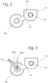
- Fig. 3 shows an embodiment of the invention in which the sensor 10, 10a, 10b is designed to carry out a continuous measurement of the axle position and/or a detection of an overload by measuring the compression and/or rebound travel using a linear sensor or by measuring defined (critical) positions (max. compression/rebound travel).
- a signal is preferably generated and triggered or transmitted.
- the assembly takes place either in the shock absorber position 10a or perpendicular to the axis 10b and measures the spring travel of the shock absorber or the axle.
- the determination of the axle pivot point and accordingly an overload can preferably be carried out by means of a linear sensor ( Fig. 3 ) take place.
- the compression/rebound travel is continuously measured using an axle position sensor mounted on the axle pivot point.
- the axle pivot point and a corresponding overload can be determined by measuring the direct axle pivot point using electrical field sensors mounted in direct or indirect proximity to the axle pivot point.
- the senor 10, 10a, 10b is preferably mounted approximately centrally on the vehicle trailer in the area of the axle body 11.
- the sensor 10, 10a, 10b can also preferably determine the spring travel of the axle, with the ground located below the axle body 11 serving as an indicator.
- a further embodiment of the invention provides that the sensor 10, 10a, 10b is an optical sensor.
- the installation position of the sensor is either near the steering knuckle on the trailer body or axle body 11 horizontally ( Fig. 1 ), mounted vertically on the axle body 11 itself ( Fig. 2 ), directly at an angle of 0-180° to the steering knuckle on the trailer body ( Fig. 3 ) or horizontally to the axle pivot point on the axle body 11 itself ( Fig. 4 ) to execute.
- the invention also applies to the detection of overloading by processing digital or analog signals, e.g. from the previously mentioned sensors, by an electronic module which is able to detect an overload of the trailer by comparing defined target values with actual values and detecting deviations from standard values.
- This is not limited to the evaluation of measured end states, but also relates to the evaluation of dynamic measured values during the journey and the detection of overloading by analysis using an electronic evaluation device, provided that the existing sensors cannot determine any end states that clearly indicate an overload.
- the values measured by the electronic evaluation module are transmitted in real time using radio technology (2G/3G/4G/5G/6G, LoRaWan, Narrowband IOT and others) via a mobile network, satellite network, Bluetooth or another radio-based technology to a central system, which then allows further monitoring of the trailer.
- the overload can be detected on an axle-selective basis or by measuring consolidated values on several axles using an additional module or an additional IT service (cloud service).
- Wired sensors or those that work via radio technology can be used. This also includes detection using so-called iBeacon sensors from Apple Inc. and sensors using the Eddystone protocol from Alphabet/Google.
Landscapes
- Physics & Mathematics (AREA)
- General Physics & Mathematics (AREA)
- Engineering & Computer Science (AREA)
- Mechanical Engineering (AREA)
- Vehicle Body Suspensions (AREA)
Applications Claiming Priority (1)
| Application Number | Priority Date | Filing Date | Title |
|---|---|---|---|
| DE102023119404 | 2023-07-21 |
Publications (1)
| Publication Number | Publication Date |
|---|---|
| EP4494902A1 true EP4494902A1 (fr) | 2025-01-22 |
Family
ID=91961767
Family Applications (1)
| Application Number | Title | Priority Date | Filing Date |
|---|---|---|---|
| EP24189741.2A Withdrawn EP4494902A1 (fr) | 2023-07-21 | 2024-07-19 | Remorque de véhicule avec un capteur pour mesurer et/ou déterminer la charge par essieu agissant sur l'essieu de la remorque de véhicule par le chargement |
Country Status (1)
| Country | Link |
|---|---|
| EP (1) | EP4494902A1 (fr) |
Citations (7)
| Publication number | Priority date | Publication date | Assignee | Title |
|---|---|---|---|---|
| US5825284A (en) * | 1996-12-10 | 1998-10-20 | Rollover Operations, Llc | System and method for the detection of vehicle rollover conditions |
| DE10025075C2 (de) * | 2000-05-20 | 2002-03-21 | Thales Instr Gmbh | Vorrichtung zum Ermitteln des Gewichtes eines Gutes, insbesondere eines Schüttgutes |
| US20050167165A1 (en) * | 2004-01-15 | 2005-08-04 | Komatsu Ltd. | Loaded weight measurement method and loaded weight measurement device for dump truck |
| KR20190073024A (ko) * | 2017-12-18 | 2019-06-26 | 현대자동차주식회사 | 차량 현가장치의 과적 축중 경고 시스템 및 방법, 이를 이용한 차량의 현가장치 내구수명 예측 시스템 및 방법 |
| DE102018214885A1 (de) * | 2018-08-31 | 2020-03-05 | Robert Bosch Gmbh | Mobile Vorrichtung und Verfahren zum Ermitteln einer Beladung eines Fahrzeugs |
| AU2018337664A1 (en) * | 2017-09-22 | 2020-04-30 | OzX IP Pty Ltd | Weight management system for a towed vehicle |
| CN214471261U (zh) * | 2020-09-17 | 2021-10-22 | 山东理工大学 | 一种高测量精度半挂车车载重量检测系统 |
-
2024
- 2024-07-19 EP EP24189741.2A patent/EP4494902A1/fr not_active Withdrawn
Patent Citations (7)
| Publication number | Priority date | Publication date | Assignee | Title |
|---|---|---|---|---|
| US5825284A (en) * | 1996-12-10 | 1998-10-20 | Rollover Operations, Llc | System and method for the detection of vehicle rollover conditions |
| DE10025075C2 (de) * | 2000-05-20 | 2002-03-21 | Thales Instr Gmbh | Vorrichtung zum Ermitteln des Gewichtes eines Gutes, insbesondere eines Schüttgutes |
| US20050167165A1 (en) * | 2004-01-15 | 2005-08-04 | Komatsu Ltd. | Loaded weight measurement method and loaded weight measurement device for dump truck |
| AU2018337664A1 (en) * | 2017-09-22 | 2020-04-30 | OzX IP Pty Ltd | Weight management system for a towed vehicle |
| KR20190073024A (ko) * | 2017-12-18 | 2019-06-26 | 현대자동차주식회사 | 차량 현가장치의 과적 축중 경고 시스템 및 방법, 이를 이용한 차량의 현가장치 내구수명 예측 시스템 및 방법 |
| DE102018214885A1 (de) * | 2018-08-31 | 2020-03-05 | Robert Bosch Gmbh | Mobile Vorrichtung und Verfahren zum Ermitteln einer Beladung eines Fahrzeugs |
| CN214471261U (zh) * | 2020-09-17 | 2021-10-22 | 山东理工大学 | 一种高测量精度半挂车车载重量检测系统 |
Similar Documents
| Publication | Publication Date | Title |
|---|---|---|
| DE112017001014T5 (de) | System und verfahren zur detektion von überbelastung, abnutzung und/oder versagen eines kugelgelenks | |
| EP2500708B1 (fr) | Dispositif et procédé de vérification de blocs, notamment de vérification de l'amortissement d'essieu dans des véhicules | |
| EP2132548B1 (fr) | Ensemble et procédé pour détecter et/ou évaluer des vibrations de corps et/ou structures en mouvement et/ou présentant un entraînement | |
| DE102016012663A1 (de) | Kopplungseinrichtung für einen Lastzug mit anhängerunabhängiger Knickwinkelsensierung | |
| DE102007020043A1 (de) | Messeinrichtung für eine Luftfeder | |
| EP4070291A1 (fr) | Système et dispositif de détection permettant de vérifier l'état d'au moins un composant d'un véhicule, et procédé de vérification d'état | |
| DE102018122059A1 (de) | Systeme und verfahren zur erkennung von anomalien in einem fahrzeugaufhängungssystem | |
| DE102012218426A1 (de) | Verfahren, Steuergerät und System zum Ermitteln eines, einen Zustand zumindest einer Komponente eines Kraftfahrzeugs kennzeichnenden Parameters | |
| DE102021124079A1 (de) | Sensoreinrichtung | |
| DE202008015740U1 (de) | Kraftfahrzeug mit elektronischer Anhängerstützlasterkennung | |
| WO2003016078A1 (fr) | Procede et dispositif permettant de faire fonctionner un equipement de surveillance et de signalisation radio d'un changement de pression et d'effectuer un reglage automatique de la pression des pneumatiques de vehicules automobiles | |
| EP3448729B1 (fr) | Dispositif de détection électronique de la charge par essieu d'un véhicule automobile | |
| DE102020214518A1 (de) | Sensoranordnung und Verfahren zum Erfassen der Last und einer Laständerung eines Fahrzeugs | |
| EP4494902A1 (fr) | Remorque de véhicule avec un capteur pour mesurer et/ou déterminer la charge par essieu agissant sur l'essieu de la remorque de véhicule par le chargement | |
| WO2023280843A1 (fr) | Dispositif de mesure de forces | |
| DE102018113138A1 (de) | Anordnung sowie Verfahren zum Erfassen und/oder Auswerten von Schwingungen | |
| DE102018207385A1 (de) | Verfahren zur Ermittlung einer Kippwahrscheinlichkeit eines Fahrzeuges, Auswerteeinheit, System und Fahrzeug | |
| DE102014214995A1 (de) | Verfahren, Vorrichtung und System zum Betreiben eines Kraftfahrzeugs | |
| DE102020007456A1 (de) | Verfahren zur Abfahrtskontrolle eines autonom fahrenden Fahrzeuges, insbesondere eines Fahrzeuggespanns | |
| DE102016208618A1 (de) | Verfahren zur Ermittlung der auf ein Zugfahrzeug an dessen Anhängerkupplung wirkenden Stützlast nach dem Ankuppeln eines Anhängers | |
| DE102010048260A1 (de) | Automatische Bestimmung eines Einfederwegs eines Rads eines Fahrzeugs | |
| DE102021112236B4 (de) | Bewegungserkennungs-Verfahren zur Erkennung einer Bewegung bei einem Fahrzeug, Monitorverfahren mittels dem ein Zustand eines Monitorsensors überprüfbar ist und Fahrzeug | |
| DE102017121865A1 (de) | Verfahren zur Überwachung der Belastung eines Fahrwerks-Bauteils beim Fahren mit einem Kraftfahrzeug und Kraftfahrzeug | |
| DE102015202868A1 (de) | Fahrzeug, Verfahren zum Betreiben eines Fahrzeugs | |
| DE102021001918A1 (de) | Verfahren zur Überwachung eines Fahrzeuges |
Legal Events
| Date | Code | Title | Description |
|---|---|---|---|
| PUAI | Public reference made under article 153(3) epc to a published international application that has entered the european phase |
Free format text: ORIGINAL CODE: 0009012 |
|
| STAA | Information on the status of an ep patent application or granted ep patent |
Free format text: STATUS: THE APPLICATION HAS BEEN PUBLISHED |
|
| AK | Designated contracting states |
Kind code of ref document: A1 Designated state(s): AL AT BE BG CH CY CZ DE DK EE ES FI FR GB GR HR HU IE IS IT LI LT LU LV MC ME MK MT NL NO PL PT RO RS SE SI SK SM TR |
|
| STAA | Information on the status of an ep patent application or granted ep patent |
Free format text: STATUS: THE APPLICATION IS DEEMED TO BE WITHDRAWN |
|
| 18D | Application deemed to be withdrawn |
Effective date: 20250723 |