EP4494790A1 - Tool bracket - Google Patents
Tool bracket Download PDFInfo
- Publication number
- EP4494790A1 EP4494790A1 EP24183109.8A EP24183109A EP4494790A1 EP 4494790 A1 EP4494790 A1 EP 4494790A1 EP 24183109 A EP24183109 A EP 24183109A EP 4494790 A1 EP4494790 A1 EP 4494790A1
- Authority
- EP
- European Patent Office
- Prior art keywords
- tilt
- axis
- cylinder
- tilting body
- spindle
- Prior art date
- Legal status (The legal status is an assumption and is not a legal conclusion. Google has not performed a legal analysis and makes no representation as to the accuracy of the status listed.)
- Pending
Links
Images




Classifications
-
- B—PERFORMING OPERATIONS; TRANSPORTING
- B23—MACHINE TOOLS; METAL-WORKING NOT OTHERWISE PROVIDED FOR
- B23B—TURNING; BORING
- B23B31/00—Chucks; Expansion mandrels; Adaptations thereof for remote control
- B23B31/02—Chucks
- B23B31/026—Chucks the radial or angular position of the tool being adjustable
-
- B—PERFORMING OPERATIONS; TRANSPORTING
- B23—MACHINE TOOLS; METAL-WORKING NOT OTHERWISE PROVIDED FOR
- B23D—PLANING; SLOTTING; SHEARING; BROACHING; SAWING; FILING; SCRAPING; LIKE OPERATIONS FOR WORKING METAL BY REMOVING MATERIAL, NOT OTHERWISE PROVIDED FOR
- B23D79/00—Methods, machines, or devices not covered elsewhere, for working metal by removal of material
- B23D79/02—Machines or devices for scraping
-
- B—PERFORMING OPERATIONS; TRANSPORTING
- B23—MACHINE TOOLS; METAL-WORKING NOT OTHERWISE PROVIDED FOR
- B23B—TURNING; BORING
- B23B51/00—Tools for drilling machines
- B23B51/10—Bits for countersinking
- B23B51/101—Deburring tools
-
- B—PERFORMING OPERATIONS; TRANSPORTING
- B23—MACHINE TOOLS; METAL-WORKING NOT OTHERWISE PROVIDED FOR
- B23B—TURNING; BORING
- B23B29/00—Holders for non-rotary cutting tools; Boring bars or boring heads; Accessories for tool holders
- B23B29/04—Tool holders for a single cutting tool
- B23B29/046—Tool holders for a single cutting tool with an intermediary toolholder
-
- B—PERFORMING OPERATIONS; TRANSPORTING
- B23—MACHINE TOOLS; METAL-WORKING NOT OTHERWISE PROVIDED FOR
- B23B—TURNING; BORING
- B23B29/00—Holders for non-rotary cutting tools; Boring bars or boring heads; Accessories for tool holders
- B23B29/04—Tool holders for a single cutting tool
- B23B29/12—Special arrangements on tool holders
-
- B—PERFORMING OPERATIONS; TRANSPORTING
- B23—MACHINE TOOLS; METAL-WORKING NOT OTHERWISE PROVIDED FOR
- B23B—TURNING; BORING
- B23B31/00—Chucks; Expansion mandrels; Adaptations thereof for remote control
- B23B31/02—Chucks
- B23B31/08—Chucks holding tools yieldably
-
- B—PERFORMING OPERATIONS; TRANSPORTING
- B23—MACHINE TOOLS; METAL-WORKING NOT OTHERWISE PROVIDED FOR
- B23B—TURNING; BORING
- B23B31/00—Chucks; Expansion mandrels; Adaptations thereof for remote control
- B23B31/02—Chucks
- B23B31/36—Chucks with means for adjusting the chuck with respect to the working-spindle
-
- B—PERFORMING OPERATIONS; TRANSPORTING
- B23—MACHINE TOOLS; METAL-WORKING NOT OTHERWISE PROVIDED FOR
- B23B—TURNING; BORING
- B23B51/00—Tools for drilling machines
- B23B51/10—Bits for countersinking
- B23B51/104—Bits for countersinking with stops
-
- B—PERFORMING OPERATIONS; TRANSPORTING
- B23—MACHINE TOOLS; METAL-WORKING NOT OTHERWISE PROVIDED FOR
- B23C—MILLING
- B23C3/00—Milling particular work; Special milling operations; Machines therefor
- B23C3/12—Trimming or finishing edges, e.g. deburring welded corners
-
- B—PERFORMING OPERATIONS; TRANSPORTING
- B23—MACHINE TOOLS; METAL-WORKING NOT OTHERWISE PROVIDED FOR
- B23C—MILLING
- B23C3/00—Milling particular work; Special milling operations; Machines therefor
- B23C3/12—Trimming or finishing edges, e.g. deburring welded corners
- B23C3/126—Portable devices or machines for chamfering edges
-
- B—PERFORMING OPERATIONS; TRANSPORTING
- B23—MACHINE TOOLS; METAL-WORKING NOT OTHERWISE PROVIDED FOR
- B23Q—DETAILS, COMPONENTS, OR ACCESSORIES FOR MACHINE TOOLS, e.g. ARRANGEMENTS FOR COPYING OR CONTROLLING; MACHINE TOOLS IN GENERAL CHARACTERISED BY THE CONSTRUCTION OF PARTICULAR DETAILS OR COMPONENTS; COMBINATIONS OR ASSOCIATIONS OF METAL-WORKING MACHINES, NOT DIRECTED TO A PARTICULAR RESULT
- B23Q1/00—Members which are comprised in the general build-up of a form of machine, particularly relatively large fixed members
- B23Q1/70—Stationary or movable members for carrying working-spindles for attachment of tools or work
-
- B—PERFORMING OPERATIONS; TRANSPORTING
- B23—MACHINE TOOLS; METAL-WORKING NOT OTHERWISE PROVIDED FOR
- B23B—TURNING; BORING
- B23B2220/00—Details of turning, boring or drilling processes
- B23B2220/08—Deburring
-
- B—PERFORMING OPERATIONS; TRANSPORTING
- B23—MACHINE TOOLS; METAL-WORKING NOT OTHERWISE PROVIDED FOR
- B23B—TURNING; BORING
- B23B2270/00—Details of turning, boring or drilling machines, processes or tools not otherwise provided for
- B23B2270/02—Use of a particular power source
- B23B2270/027—Pneumatics
Definitions
- the present invention relates to a tool bracket.
- Patent Literature 1 A deburring tool capable of tilting a tool has been proposed ( JP2022-074292 A ; hereinafter, Patent Literature 1).
- the deburring tool 100 of Patent Literature 1 includes a housing 1 having a shank 11 disposed along a shank axis 15, a transmission rod 3, a tilting shaft 4, and a tilt correction mechanism 9.
- the tilting shaft 4 includes a flange portion 41, a receiving portion 41a through which the transmission rod passes, a rod portion 42 holding the cutter 101, and a spherical bush 24 having a tilting center 25 on the shank axis 15.
- the tilting shaft 4 can be tilted about a tilting center 25.
- the deburring tool of Patent Literature 1 is mounted on a rotating spindle of a machining center or the like.
- the deburring tool of Patent Literature 1 thus cannot be applied to, for example, a robot that does not have a rotating spindle.
- An object of the present invention is to provide a tool bracket in which a spindle body is inserted and the spindle body can be smoothly tilted.
- a first aspect of the present invention provides a tool bracket, including:
- a second aspect of the present invention provides a tool bracket, including:
- the tool bracket according to the present invention allows the spindle body to be inserted and to be smoothly tilted.
- a deburring tool 10 includes a tool bracket 13 and a spindle body 11.
- FIG. 1 is a sectional view taken along line I-I in FIG. 2 .
- FIG. 1 shows a state in which the spindle body 11 is not tilted.
- the deburring tool 10 is connected to a robot 6 and an air source 8.
- the tool bracket 13 includes a housing 15, a piston 21, a tilting body 17, a coupling 18, a rotation stopper 19, a basal end cover 27, and a distal end cover 25.
- the housing 15 has a hollow shape.
- the piston 21, the tilting body 17, and the rotation stopper 19 are disposed inside the housing 15 from the basal end.
- the housing 15 has a cylinder chamber 15a, a seat surface 15c, and a distal end opening 15d in this order from a basal end.
- the housing 15 is attached to, for example, a distal end of an arm of the robot 6.
- the housing 15 may have a rectangular parallelepiped outer shape.
- the cylinder chamber 15a is disposed around the cylinder axis 2.
- the cylinder chamber 15a includes a cylinder portion 15a2 and a small-diameter guide portion 15a1.
- the cylinder portion 15a2 is disposed in a central portion of the housing 15.
- the small-diameter guide portion 15a1 has a diameter smaller than the cylinder portion 15a2.
- the small-diameter guide portion 15a1 is connected to the cylinder portion 15a2 and opens to the basal end of the housing 15.
- the seat surface 15c is disposed at a distal end portion of the housing 15.
- the seat surface 15c is a plane perpendicular to the cylinder axis 2.
- the seat surface 15c is connected to the cylinder chamber 15a via the rotation stopper 19.
- the distal end opening 15d opens from the seat surface 15c to the distal end of the housing 15.
- the distal end opening 15d increases in diameter toward the distal end.
- the housing 15 has a fluid-port 15f.
- the fluid-port 15f is connected to the cylinder portion 15a2.
- the fluid-port 15f is connected to the air source 8.
- the air source 8 supplies compressed air to the cylinder portion 15a2 via the fluid-port 15f.
- the piston 21 has a hollow cylindrical shape.
- the piston 21 includes a head portion 21b, a sleeve 21a, a recess (action portion) 21d, a basal end opening 21c, a seal 21e, and a seal 21f.
- the head portion 21b which is a hollow-cylinder, reciprocates in the cylinder portion 15a2.
- the recess 21d has a larger diameter toward the distal end.
- the recess 21d is, for example, a conical surface centered on the cylinder axis 2.
- the sleeve 21a is connected to the basal end of the head portion 21b.
- the sleeves 21a are guided to the small-diameter guide portion 15a1.
- the basal end opening 21c is an inner surface of the sleeve 21a.
- the basal end opening 21c may also be a conical surface with a larger diameter toward the basal end.
- the basal end opening 21c is connected to the recess 21d.
- the seal 21e is mounted on an outer cylindrical surface of the head portion 21b.
- the seal 21f is mounted on an outer cylindrical surface of the sleeve 21a.
- the tilting body 17 is hollow cylindrical or spherical.
- the tilting body 17 has a convex spherical surface (centering portion) 17a, a head surface 17b, a sleeve 17c, and an insertion hole 17d.
- the convex spherical surface 17a is disposed at a basal end portion of the tilting body 17.
- the convex spherical surface 17a comes into contact with and slides on the recess 21d.
- the convex spherical surface 17a has a tilt center 17e.
- the tilt center 17e is the center of the convex spherical surface 17a.
- the tilt axis 3 passes through the tilt center 17e.
- the head surface 17b is located at a distal end portion of the tilting body 17.
- the head surface 17b is, for example, a flat surface.
- the head surface 17b which is a flat surface, is perpendicular to the tilt axis 3.
- the sleeve 17c extends toward the distal end from the head surface 17b.
- the sleeve 17c is a hollow right cylinder.
- the insertion hole 17d is an inner surface of the sleeve 17c.
- the insertion hole 17d passes through the tilting body 17 around the tilt axis 3.
- the insertion hole 17d is a cylindrical hole.
- the spindle body 11 is inserted into the insertion hole 17d.
- the spindle body 11 passes through the tool bracket 13.
- the spindle body 11 includes a body 11a, a spindle 11b, and a spindle motor 11c.
- the spindle 11b is rotatably supported on the body 11a about the tilt axis 3.
- a tip tool 1 is attached to the spindle 11b.
- the spindle motor 11c which is disposed in the body 11a, is connected to the spindle 11b. For example, the spindle motor 11c rotates the spindle 11b in the rotational direction 5 (counterclockwise as viewed from the distal end).
- the coupling 18 has a hollow cylindrical shape.
- the coupling 18 fastens the sleeve 17c to the spindle body 11.
- the coupling 18 is, for example, a rigid coupling.
- the rotation stopper 19 includes a plurality of receiving grooves 19a, a plurality of rotation stopper pin (rotation member) 19b, and a pin hole 19c.
- the plurality of receiving grooves 19a are arranged rotationally symmetrically with respect to the cylinder axis 2 in the inner diameter portion of the housing 15.
- Each receiving groove 19a is a square groove extending parallel to the cylinder axis 2 and has a rectangular cross section.
- An abutment surface 19a1 is a side of the receiving groove 19a opposite to the rotational direction 5.
- the abutment surface 19a1 is a plane passing through the cylinder axis 2.
- a plurality of the pin holes 19c are arranged on the tilting body 17. Each of the pin hole 19c extends through the tilt center 17e and parallel to the abutment surface 19a1 on a plane perpendicular to the tilt axis 3.
- the pin hole 19c is a cylindrical hole.
- the rotation stopper 19 has the same number of rotation stopper pins 19b as the receiving grooves 19a.
- the plurality of rotation stopper pins 19b are arranged rotationally symmetrically with respect to the tilt axis 3.
- the rotation stopper pin 19b includes a shaft 19b1 and a bulging portion 19b2.
- the shaft 19b1 is inserted into the pin hole 19c.
- the bulging portion 19b2 protrudes radially from the tilting body 17.
- a play (gap) is provided between the bulging portion 19b2 and the receiving groove 19a.
- the rotation stopper pin 19b has an abutting spherical surface 19b3.
- the basal end cover 27 covers between the basal end surface of the housing 15 and the spindle body 11.
- the basal end cover 27 prevents foreign matter, cutting coolant, or the like from entering between the cylinder chamber 15a, the basal end opening 21c, and the spindle body 11.
- the distal end cover 25 covers between the distal end surface of the housing 15 and the spindle body 11 or the coupling 18.
- the distal end cover 25 prevents foreign matter, cutting coolant, or the like from entering between the spindle body 11 and the distal end opening 15d.
- FIGs. 4 and 5 show a situation in which the deburring tool 10 performs deburring of the workpiece 7.
- FIG. 4 is a sectional view taken along line IV-IV in FIG. 5 .
- the workpiece 7 has a burr 7a.
- the two-dot chain line of the burr 7a in FIG. 5 indicates a shape of the dropped part.
- the side surface of the workpiece 7 has a curved surface that is convex toward the deburring tool 10 as viewed from the basal end along the cylinder axis 2.
- the burr 7a protrudes from the side surface of the workpiece 7.
- the spindle 11b rotates in the rotational direction 5.
- the air source 8 supplies compressed air to the cylinder chamber 15a.
- the tip tool 1 when the tip tool 1 is separated from the workpiece 7, the tip tool 1 does not receive a large moment load F1 (see FIG. 4 ).
- the piston 21 is moved to the distal end by the compressed air supplied to the cylinder chamber 15a.
- the head surface 17b abuts against the seat surface 15c. This suppresses tilting of the spindle body 11.
- the tilt axis 3 substantially coincides with the cylinder axis 2.
- the tilt axis 3 is easily stabilized.
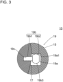
- the spindle body 11 When the spindle 11b starts to rotate, the spindle body 11 also attempts to rotate. As shown in FIG. 3 , the bulging portion 19b2 of the rotation stopper pin 19b abuts on the abutment surface 19a1 of the receiving groove 19a to prevent the spindle body 11 from rotating.
- the tip tool 1 is brought into contact with the workpiece 7 to perform deburring.
- the robot 6 moves the housing 15 along a linear trajectory 41 from a position 15p toward a position 15q.
- the tip tool 1 moves from a position 1p to a position 1q by drawing a trajectory 42 so as to trace the shape of the side surface of the workpiece 7.
- the tip tool 1 scrapes off the burr 7a.
- the tilting body 17 and the spindle body 11 are inclined integrally with one point 43 around the head surface 17b as a center. Then, while the convex spherical surface 17a is in contact with the recess 21d, the piston 21 is pushed upward toward the basal end. At this time, the tilting body 17 is tilted while the convex spherical surface 17a slides in the recess 21d. The tilt center 17e moves along the cylinder axis 2 toward the basal end.
- the recess 21d has a circular cross section centered on the cylinder axis 2.
- the convex spherical surface 17a and the recess 21d are thus substantially in contact with each other around the entire circumference.
- the tilting body 17 pushes up the piston 21 along the cylinder axis 2 with the tilt center 17e at an action point.
- the urging force F2 applied by the tilting body 17 to the piston 21 has the cylinder axis 2 as an action line.
- the air is compressible fluid.
- the piston 21 can thus move toward the basal end against the pressure of the compressed air supplied to the piston chamber.
- the piston 21 receives the urging force F2 along the cylinder axis 2, the inclination of the piston 21 is suppressed.
- the piston 21 can thus smoothly move along the cylinder axis 2.
- the piston 21 urges the tilting body 17 toward the distal end by the pressure of the compressed air.
- the tilting body 17 thus remains in contact with the seat surface 15c.
- the bulging portion 19b2 and the receiving groove 19a come into contact with each other while being twisted.
- the contact resistivity between the bulging portion 19b2 and the receiving groove 19a is small. The tilting body 17 is thus easily tilted smoothly.
- the operator teaches the robot 6 to determine the trajectory 41 and the speed of the deburring tool 10.
- the teaching of the robot 6 is carried out with the tilt axis 3 substantially coinciding with the cylinder axis 2.
- the head surface 17b abuts against the seat surface 15c to easily stabilize the posture of the spindle body 11.
- the operator can thus easily teach the robot 6. Further, as the posture of the tilt axis 3 is stable when the robot 6 moves the deburring tool 10, contact of the deburring tool 10 with the workpiece 7, the safety fence, and the worker is suppressed.
Landscapes
- Engineering & Computer Science (AREA)
- Mechanical Engineering (AREA)
- Physics & Mathematics (AREA)
- Optics & Photonics (AREA)
- Milling Processes (AREA)
- Constituent Portions Of Griding Lathes, Driving, Sensing And Control (AREA)
- Grinding And Polishing Of Tertiary Curved Surfaces And Surfaces With Complex Shapes (AREA)
- Milling, Broaching, Filing, Reaming, And Others (AREA)
Applications Claiming Priority (1)
| Application Number | Priority Date | Filing Date | Title |
|---|---|---|---|
| JP2023118061A JP2025015013A (ja) | 2023-07-20 | 2023-07-20 | 工具ブラケット |
Publications (1)
| Publication Number | Publication Date |
|---|---|
| EP4494790A1 true EP4494790A1 (en) | 2025-01-22 |
Family
ID=91760471
Family Applications (1)
| Application Number | Title | Priority Date | Filing Date |
|---|---|---|---|
| EP24183109.8A Pending EP4494790A1 (en) | 2023-07-20 | 2024-06-19 | Tool bracket |
Country Status (5)
| Country | Link |
|---|---|
| US (1) | US12472563B2 (https=) |
| EP (1) | EP4494790A1 (https=) |
| JP (1) | JP2025015013A (https=) |
| KR (1) | KR20250015865A (https=) |
| CN (1) | CN119328240A (https=) |
Citations (5)
| Publication number | Priority date | Publication date | Assignee | Title |
|---|---|---|---|---|
| DE3042939A1 (de) * | 1979-12-10 | 1981-06-11 | Hans Rümlang Wiederkehr | Werkzeughalter fuer ein rotierendes werkzeug |
| US6352394B1 (en) * | 1999-04-29 | 2002-03-05 | Dcm, Tech | Flex drive tool |
| US20050180829A1 (en) * | 2003-07-25 | 2005-08-18 | Lawson Douglas K. | Pneumatically driven deburring tool having an articulated air joint |
| KR102147044B1 (ko) * | 2020-01-31 | 2020-08-21 | 서삼열 | 면취 가공용 디버링 툴 홀더 |
| JP2022074292A (ja) | 2020-11-04 | 2022-05-18 | 株式会社スギノマシン | バリ取り工具及びバリ取り方法 |
Family Cites Families (8)
| Publication number | Priority date | Publication date | Assignee | Title |
|---|---|---|---|---|
| US1782633A (en) * | 1926-04-27 | 1930-11-25 | Bernard P Schiltz | Flexible driving connection for tool holders |
| US3359008A (en) * | 1965-10-22 | 1967-12-19 | Robert H Stimmerman | Boring tool holder for drilling and reaming operations |
| US4332066A (en) * | 1980-01-07 | 1982-06-01 | General Dynamics Corporation | Compliance mechanism |
| US4984942A (en) * | 1990-06-04 | 1991-01-15 | Leonard Holtz | Tap wrench |
| US7726919B1 (en) * | 2005-02-01 | 2010-06-01 | Rottler Manufacturing Inc. | Resurfacing machine tool |
| AT512049B1 (de) * | 2012-01-30 | 2013-05-15 | Steger Heinrich | Bearbeitungsvorrichtung für ein zahntechnisches werkstück |
| JP6041317B2 (ja) * | 2014-06-26 | 2016-12-07 | 株式会社ファインテクノ | 加工工具 |
| CN106217246A (zh) * | 2016-09-22 | 2016-12-14 | 侯治国 | 一种径向柔性去毛刺主轴 |
-
2023
- 2023-07-20 JP JP2023118061A patent/JP2025015013A/ja active Pending
-
2024
- 2024-06-19 EP EP24183109.8A patent/EP4494790A1/en active Pending
- 2024-06-25 KR KR1020240082951A patent/KR20250015865A/ko active Pending
- 2024-06-28 US US18/759,763 patent/US12472563B2/en active Active
- 2024-07-08 CN CN202410909300.5A patent/CN119328240A/zh active Pending
Patent Citations (5)
| Publication number | Priority date | Publication date | Assignee | Title |
|---|---|---|---|---|
| DE3042939A1 (de) * | 1979-12-10 | 1981-06-11 | Hans Rümlang Wiederkehr | Werkzeughalter fuer ein rotierendes werkzeug |
| US6352394B1 (en) * | 1999-04-29 | 2002-03-05 | Dcm, Tech | Flex drive tool |
| US20050180829A1 (en) * | 2003-07-25 | 2005-08-18 | Lawson Douglas K. | Pneumatically driven deburring tool having an articulated air joint |
| KR102147044B1 (ko) * | 2020-01-31 | 2020-08-21 | 서삼열 | 면취 가공용 디버링 툴 홀더 |
| JP2022074292A (ja) | 2020-11-04 | 2022-05-18 | 株式会社スギノマシン | バリ取り工具及びバリ取り方法 |
Also Published As
| Publication number | Publication date |
|---|---|
| JP2025015013A (ja) | 2025-01-30 |
| CN119328240A (zh) | 2025-01-21 |
| US12472563B2 (en) | 2025-11-18 |
| US20250025943A1 (en) | 2025-01-23 |
| KR20250015865A (ko) | 2025-02-03 |
Similar Documents
| Publication | Publication Date | Title |
|---|---|---|
| US9597093B2 (en) | Temporarily fixable angled drill | |
| KR20180130288A (ko) | 스핀들 장치 및 그의 작동방법 | |
| KR102675617B1 (ko) | 처리 공구 | |
| US4338038A (en) | Ball-and-socket joint for multiarticulate arm | |
| US10619676B2 (en) | Coupling and method for fixing the same | |
| EP1869332B1 (en) | Ball holding, latching and locking applications using radial and axial springs | |
| JP4665440B2 (ja) | 加工工具 | |
| EP4494790A1 (en) | Tool bracket | |
| EP4494789A1 (en) | Tool bracket, deburring tool with tool bracket, and deburring method | |
| KR20190046915A (ko) | 다중 연결 구동 샤프트 | |
| JP5035535B2 (ja) | サークリップ取付け用工具 | |
| CN117255724A (zh) | 加工工具 | |
| US4861132A (en) | Self-aligning precision guide pin | |
| JP2005034952A (ja) | コネクティングロッド用クラッキング溝の加工装置 | |
| EP3560639A1 (en) | A clamping device | |
| EP1848559B1 (en) | Self-centering drill bit chuck | |
| US20240075541A1 (en) | Deburring tool | |
| KR20070050097A (ko) | 비원형 연결부를 갖는 공구 | |
| JP2003117787A (ja) | バリ取り装置 | |
| EP0733439A1 (en) | Support structure of an anvil pin in a cam-type impact wrench | |
| JP2876103B2 (ja) | 主軸アタッチメントツール | |
| US6962489B2 (en) | Moineau pumping device having a ball coupling | |
| JP6980261B2 (ja) | 工具保持具 | |
| JPS60177873A (ja) | カム式インパクトレンチにおけるアンビルピンの支持構造 | |
| KR102407300B1 (ko) | 핸들 장치 및 천공기 |
Legal Events
| Date | Code | Title | Description |
|---|---|---|---|
| PUAI | Public reference made under article 153(3) epc to a published international application that has entered the european phase |
Free format text: ORIGINAL CODE: 0009012 |
|
| STAA | Information on the status of an ep patent application or granted ep patent |
Free format text: STATUS: THE APPLICATION HAS BEEN PUBLISHED |
|
| AK | Designated contracting states |
Kind code of ref document: A1 Designated state(s): AL AT BE BG CH CY CZ DE DK EE ES FI FR GB GR HR HU IE IS IT LI LT LU LV MC ME MK MT NL NO PL PT RO RS SE SI SK SM TR |
|
| STAA | Information on the status of an ep patent application or granted ep patent |
Free format text: STATUS: REQUEST FOR EXAMINATION WAS MADE |
|
| 17P | Request for examination filed |
Effective date: 20250617 |